JP3146574U - Bottom composite lock box - Google Patents
Bottom composite lock box Download PDFInfo
- Publication number
- JP3146574U JP3146574U JP2008006399U JP2008006399U JP3146574U JP 3146574 U JP3146574 U JP 3146574U JP 2008006399 U JP2008006399 U JP 2008006399U JP 2008006399 U JP2008006399 U JP 2008006399U JP 3146574 U JP3146574 U JP 3146574U
- Authority
- JP
- Japan
- Prior art keywords
- flap
- bottom plate
- flaps
- plate forming
- box
- Prior art date
- Legal status (The legal status is an assumption and is not a legal conclusion. Google has not performed a legal analysis and makes no representation as to the accuracy of the status listed.)
- Expired - Lifetime
Links
Images


Landscapes
- Cartons (AREA)
Abstract
【課題】封緘金具等の封緘用資材の使用をやめ、箱組立時の作業性と廃棄時の分別作業性や環境問題を解決し、底面に相当の荷重がかかっても箱が開くことが防止できる複合ロックを備えた封緘力の高い野菜類の収納箱を提供する。
【解決手段】先に閉じた前記底板形成用フラップ7の差込孔15a、15aに、切込み16a,16aが噛み合うように押し込むことで、前記短辺側のフラップ7の下に、略三角の係止爪部14a,14bが重なるように係合させてロックする(1次ロック)。続いて、底板形成用フラップ6,8を内側に押し込み、その後該フラップ6,8に設けた切込み17aに台形状のフラップの先端部5aを押し込んで、底板形成用フラップ6,8の下で前記フラップの先端部5aと底板形成用フラップ7の先端が突き合わせとなるようにする(2次ロック)。
【選択図】図2[PROBLEMS] To eliminate the use of sealing materials such as sealing metal fittings, solve workability during box assembly, separation workability during disposal, and environmental problems, and prevent the box from opening even when a considerable load is applied to the bottom surface. Provide a vegetable box with high sealing power and a composite lock that can be used.
The bottom plate forming flap 7 is closed by inserting it into the insertion holes 15a, 15a so that the cuts 16a, 16a engage with each other, so that a substantially triangular engagement is formed under the short side flap 7. The pawl portions 14a and 14b are engaged and locked so as to overlap (primary lock). Subsequently, the bottom plate forming flaps 6 and 8 are pushed inward, and then the tip 5a of the trapezoidal flap is pushed into the notch 17a provided in the flaps 6 and 8, so that the bottom plate forming flaps 6 and 8 are below the bottom plate forming flaps 6 and 8. The front end 5a of the flap and the front end of the bottom plate forming flap 7 are brought into contact with each other (secondary lock).
[Selection] Figure 2
Description
本考案は、根菜類又は果実などの比較的重いものを収納するに好適な段ボール等の厚紙製包装箱に関するものである。 The present invention relates to a cardboard packaging box such as cardboard suitable for storing relatively heavy items such as root vegetables or fruits.
従来、青果物を箱詰めして出荷する場合、包装箱には工場生産され組み立てた状態で納品されたJIS−Z1507の0201形式(旧A−1形)の箱が多用されている。この0201形式の箱は、長方形状の4側板を一方向に連接し、その4側板の上下に箱の底面及び天面を封鎖するため、それぞれ内フラップ及び外フラップを連接してなるほぼ直方体形状の箱である。この箱に大きさが不揃いであったり、重量のある青果物をほぼ満杯に収納して出荷されるので、商品を収納する際には内外フラップで簡単に閉じロックできるように構成し、また収納物の重みで底面のフラップが落ち込んだり、底面が開くことがないように抜けにくくし、フラップの重なった部分をステッチャとよばれる金具やテープ等の封緘用副資材により接合して出荷していた。 Conventionally, when packaging fruits and vegetables, JIS-Z1507 0201 type (formerly A-1 type) boxes manufactured and delivered in an assembled state are often used as packaging boxes. This 0201 type box has a rectangular parallelepiped shape in which rectangular four-side plates are connected in one direction, and the bottom and top surfaces of the box are sealed above and below the four-side plates. Box. This box is not fully sized or is filled with heavy fruits and vegetables, so it can be easily closed and locked with internal and external flaps when storing goods. The bottom of the flap does not drop or the bottom does not open so that it is difficult to come off, and the overlapped portion of the flap is joined with a secondary material for sealing such as a metal fitting or tape called a stitcher.
しかし、前述の組立作業は、封緘金具とその打込みマシンを用意する必要があるので工場で組み立てる必要があり、しかも封緘金具やテープ等の封緘用副資材のコストがかかる上、底面に封緘金具を打ち込むことにより、箱内の収納物を傷つけてしまうおそれがある。また使用後の金具は段ボール紙などの可燃物と一緒に焼却することができず、分別の必要がある。 However, the above-mentioned assembly work requires the preparation of a sealing metal fitting and its driving machine, so it is necessary to assemble at the factory, and in addition to the cost of secondary materials for sealing such as a sealing metal fitting and tape, a sealing metal fitting is attached to the bottom. There is a risk that the stored items in the box may be damaged by driving. Also, the metal fittings after use cannot be incinerated with combustibles such as corrugated paper, and need to be separated.
一般に、量販店で青果物の箱は陳列時に開封作業と使用後の解体作業などでの安全性及び簡便性が要求されている。また、封緘用副資材によるゴミの発生が量販店などでは敬遠されている。さらにまた、使用済みの箱を古紙として再利用する場合にあっても不純物として紙片から金属を分別する手間がかかり、また、箱の開梱時や、開梱後の分別において金属針により怪我をすることもあり、取り扱いには特に注意を払わなければならないという不具合がある。 In general, a box of fruits and vegetables is required to be safe and simple in unpacking operations and dismantling operations after use at the time of display in mass merchandising stores. Moreover, the generation of trash from secondary materials for sealing is avoided at mass merchandisers. Furthermore, even when a used box is reused as waste paper, it takes time and effort to separate the metal from the piece of paper as an impurity, and injuries are caused by a metal needle when unpacking the box and during sorting after unpacking. There is a problem that special care must be taken in handling.
本考案の目的は、封緘金具やテープ等の封緘用副資材の使用を廃止して、箱組立時の作業性と廃棄時の分別作業性や環境問題を解決すると同時に、底面に相当の荷重がかかっても内外フラップが落ち込んで箱が開くことが防止できる複合ロックを備えた封緘力の高い野菜類の収納箱を提供するものである。 The purpose of the present invention is to eliminate the use of secondary materials for sealing, such as sealing metal fittings and tapes, to solve workability during box assembly, separation workability during disposal, and environmental problems, and at the same time, a considerable load is applied to the bottom surface. It is intended to provide a vegetable storage box having a high sealing power, which is provided with a composite lock that can prevent the inner and outer flaps from falling and the box from being opened even if it is applied.
上記課題を解決するために本考案は、
長辺側の対向側板(1,3)と、短辺側の対向側板(2,4)と、これらの対向側板の下端にそれぞれ連設された底板形成用フラップ(5,7,6,8)と、同じくこれらの対向側板(1,3,2,4)の上端にそれぞれ連設された上蓋形成用フラップ(9,11,10,12)とを備えて成る平面形状が矩形の厚紙製包装箱であって、
前記長辺側の対向側板(1,3)の下端に連設された底板形成用フラップ(5,7)は短辺側の対向側板(2,4)の幅方向中央部において先端同士が互いに突き合わせ状態となるような大きさに形成し、その一方のフラップは先端部(5a)を台形状に形成し、他方のフラップは中央部で略L形または逆L形の互いに向き合う1組の差込孔(15a、15a)を設けてなり、前記短辺側の対向側板(2,4)の下端に連設された底板形成用フラップ(6,8)は一側辺に、そのフラップの先端角部を挟み1組の切込み(16a,16b)を設けることで係止爪部(14a,14b)を設け、またそのフラップの先端中央位置には差込孔(17a,17b)を設けてなり、
先に閉じた前記底板形成用フラップ(7)の差込孔(15a、15a)に、切込み(16a,16b)を押し込むことで、先に閉じられた前記短辺側のフラップ(7)の下に係止爪部(14a,14b)が重なるように係合させ、底板形成用フラップ(6,8)に設けた差込孔(17a,17b)に台形状フラップの先端部(5a)を押し込んで、底板形成用フラップ(6,8)の下で前記フラップの先端部(5a)と底板形成用フラップ(7)の先端が突き合わせとなるように構成したことを特徴とするものである。
In order to solve the above problems, the present invention
Opposite side plates (1, 3) on the long side, opposing side plates (2, 4) on the short side, and bottom plate forming flaps (5, 7, 6, 8) connected to the lower ends of these opposing side plates, respectively. ) And upper lid forming flaps (9, 11, 10, 12) connected to the upper ends of these opposing side plates (1, 3, 2, 4), respectively, and are made of thick cardboard with a rectangular planar shape. A packaging box,
The bottom plate-forming flaps (5, 7) connected to the lower ends of the long side opposing side plates (1, 3) are mutually connected at the tips in the width direction central portion of the short side opposing side plates (2, 4). It is sized so as to be in a butted state, one of its flaps has a tip (5a) formed in a trapezoidal shape, and the other flap is a pair of opposing L-shaped or inverted L-shaped ones facing each other at the center. The bottom plate forming flaps (6, 8), which are provided with insertion holes (15a, 15a) and are continuously provided at the lower ends of the opposed side plates (2, 4) on the short side, are arranged on one side and the tips of the flaps. By providing a pair of cuts (16a, 16b) across the corner, a locking claw (14a, 14b) is provided, and an insertion hole (17a, 17b) is provided at the center of the tip of the flap. ,
By pushing the cuts (16a, 16b) into the insertion holes (15a, 15a) of the bottom plate-forming flap (7) closed earlier, the bottom side of the flap (7) on the short side closed earlier Are engaged so that the latching claws (14a, 14b) overlap with each other, and the tip (5a) of the trapezoidal flap is pushed into the insertion holes (17a, 17b) provided in the bottom plate forming flaps (6, 8). Thus, it is characterized in that the front end portion (5a) of the flap and the front end of the bottom plate forming flap (7) are in contact with each other under the bottom plate forming flaps (6, 8).
又本考案においては、底板形成用フラップ(7)の略L形または逆L形の差込孔(15a、15a)のそれぞれの外側に、罫線(15c)を介して外れ止め片(15b,15b)を連設したことを特徴としている。さらに又本考案においては、底板形成用フラップ(6,8)はその連設線と平行な罫線(13,13)より折り曲げうるように形成され、且つそのフラップ(6,8)の先端よりに設けた差込孔(17a,17b)には切り込みとの間が短辺側のフラップ6,8の先端に向って広がるように罫線(17c,17c)を形成し、該罫線を介して外れ止め片(17d)を設けたことを特徴としている。
In the present invention, the stopper plate (15b, 15b) is provided on the outside of the substantially L-shaped or inverted L-shaped insertion hole (15a, 15a) of the bottom plate forming flap (7) via the ruled line (15c). ). Furthermore, in the present invention, the bottom plate forming flaps (6, 8) are formed so as to be bendable from the ruled lines (13, 13) parallel to the continuous lines and from the front ends of the flaps (6, 8). Ruled lines (17c, 17c) are formed in the provided insertion holes (17a, 17b) so that the gap between the cuts extends toward the tips of the
本考案の包装箱は、底板の組立てのために接着剤や封緘金具の固定部は不要であり、先に閉じた長辺側底板形成用フラップの差込孔(15a、15a)に、切込み(16a,16b)を押し込むことで、先に閉じられた前記短辺側のフラップの下に係止爪部(14a,14b)が重なるように係合させてロックし、また、短辺側底板形成用フラップに設けた差込孔(17b,17b)に台形状のフラップの先端部(5a)を押し込んで、底板形成用フラップ(6,8)の下で前記フラップの先端部(5a)と底板形成用フラップ(7)の先端が突き合わせとするという極めて簡単な作業で底板の組立てが行えるものである。
また、底板形成用フラップ(7)の略L形または逆L形をした差込孔(15a、15a)のそれぞれの外側に、罫線を介して外れ止め片(15b,15b)を連設し、また底板形成用フラップ(6,8)はその連設線と平行な罫線(13,13)より折り曲げうるように形成され、且つそのフラップ(6,8)の先端よりに設けた切込み(17a,17a)の外側に切り込みとの間が短辺側のフラップ6,8の先端に向って広がるように罫線(17c,17c)を形成し、該罫線を介して外れ止め片(17d)を設けたので、底板形成用フラップ(7)が差込孔(15a、15a)から抜け難くなり、底板形成用フラップ(6,8)は差込孔(17a,17b)から抜け難くなる。
The packaging box of the present invention does not require an adhesive or a fixing part for sealing metal fitting for assembling the bottom plate, and cuts into the insertion holes (15a, 15a) of the flaps for forming the long side bottom plate closed earlier ( 16a and 16b) are pressed and locked so that the locking claw portions (14a and 14b) overlap with the previously closed short side flaps, and the short side plate is formed. The tip end (5a) of the trapezoidal flap is pushed into the insertion holes (17b, 17b) provided in the flap for use, and the tip end (5a) of the flap and the bottom plate under the bottom plate forming flap (6, 8) The bottom plate can be assembled by an extremely simple operation in which the front end of the forming flap (7) is abutted.
In addition, on the outside of each of the insertion holes (15a, 15a) having a substantially L shape or an inverted L shape of the bottom plate forming flap (7), a retaining piece (15b, 15b) is continuously provided via a ruled line, Further, the bottom plate forming flaps (6, 8) are formed so as to be bendable from the ruled lines (13, 13) parallel to the continuous lines, and the notches (17a, A ruled line (17c, 17c) is formed on the outside of 17a) so that the gap between the cuts extends toward the tips of the
次に、本考案の実施の形態を図面に基づいて説明するが、この包装箱は、にんじん、大根、キャベツなどの箱底面に相当な荷重がかかる青果物を出荷する場合に好適である。しかし本考案の箱は青果物に限定されるものではない。 Next, an embodiment of the present invention will be described with reference to the drawings. This packaging box is suitable for shipping fruits and vegetables such as carrots, radishes, cabbages, and the like that have a considerable load on the bottom of the box. However, the box of the present invention is not limited to fruits and vegetables.
図1は、本考案の第1の実施例を示す段ボール箱のシート(ブランクと称する)を示すものである。このブランクは、一例としてほぼ長方形をした1枚の段ボールシートより形成されている。 FIG. 1 shows a sheet (referred to as a blank) of a cardboard box showing a first embodiment of the present invention. As an example, this blank is formed from a single rectangular cardboard sheet.
本実施の形態に示す箱は、前記シートの中央部に、箱の対向する各側面のうち長い面(長手面)を構成する一組の長辺側の側板1、3と、短い面(幅面)を構成する一組の短辺側の側板2、4が折線を介し一方向に連接されている。また一対の短側板2、4にはその中央上部に手掛け穴が設けられている。そして側板1、3及び2、4の下部には底板形成用フラップ5、7及び6,8が折線を介して連接されている。また各一対の側板1、3および2、4の上部には上蓋形成用フラップ9、11及び10、12が折線を介して連接されている。
The box shown in the present embodiment includes a pair of
底板形成用フラップ5、7及び6,8には、底面封緘時に相当の荷重がかかっても底面が落ち込んで開くことない、つぎのような構成の底面複合ロック機構が形成されている。すなわち長辺側の対向側板1,3の下端に連設された底板形成用フラップ5,7は、短辺側の対向側板2,4の幅方向中央部において先端同士が互いに突き合わせ状態となるような大きさに形成し、一方のフラップ5の先端部は先窄まりの略台形状5aに形成されている。他方のフラップ7は矩形であるが、中央部に略L形または逆L形の、互いに向き合う1組の差込孔15a、15aを設けている。
The bottom
一方、短辺側の対向側板2,4の下端に連設された底板形成用フラップ6,8は、その一側辺にそのフラップの先端角部を挟んで1組の切込み16a,16bを設けることで、略三角をした係止爪部14a,14bを設ける。また、そのフラップの先端側略中央位置には切込み17a,17bを設けた構成となっている。切込み17a,17bの外側に切込みとの間が短辺側のフラップ6,8の先端に向って広がるように罫線17c,17cを形成し、該罫線を介して外れ止め片17dを設けた構成となっている。
なお符号19、19aは、側板1の端部に連接した糊代と、その端に設けた糊代である。
On the other hand, the bottom
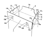
次にブランクの組み立て方について説明すると、まず4枚の側板1,3,2,4を糊代19、19aを介して角筒状に連繋する(図2)。その後、先に閉じた前記底板形成用フラップ7の差込孔15a、15aに、切込み16a,16aが噛み合うように押し込むことで、先に閉じられた前記短辺側のフラップ7の下に、略三角の係止爪部14a,14bが重なるように係合させて図3、図4に示したようにロックする(1次ロック)。
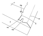
続いて、底板形成用フラップ6,8を図5のように内側に押し込み、その後該フラップ6,8に設けた切込み17a,17bに台形状のフラップの先端部5aを図6のように押し込んで、底板形成用フラップ6,8の下で前記フラップの先端部5aと底板形成用フラップ7の先端が突き合わせとなるようにする(2次ロック)。
Next, the method of assembling the blank will be described. First, the four
Subsequently, the bottom
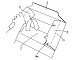
このようにして底面を組み立てた後、上蓋形成用フラップ9,11および10,12を広げ、箱内に青果物を収容する。フラップ9,11,10,12により天面を封緘する場合は、図7〜9に示すように、まず長辺側のフラップ9を内側に90度折り曲げ、続いて短辺側のフラップ12をその上に重ねるように折り曲げる。さらに続いて、短辺側フラップ12の上に重なるように長辺側のフラップ11を折り曲げ、最後に残りのフラップ10を連設線と平行な罫線20より折り曲げる。長辺側のフラップ9は、その一端よりに斜めの罫線21と切除部22を有している。一方、フラップ10は切除部22に対応する切除部23を有している。そして封緘時には、罫線20によりを前記フラップ9と11の上に重ねるように折り曲げると共に、前記フラップ9の一端に設けた切除部22に、これと隣接するフラップ10の他端に設けた切除部23を差し込むことにより天面のフラップ9〜12が互いに係合して封緘されるようになっている。このようにして箱の天面を封緘するときは、天面フラップの重ね合せ部(天面の四隅)を封緘金具で止めて封緘した場合と同様に、内外フラップの開きを防止する作用を奏する。そればかりでなく内部に野菜が一杯に詰まっていても、内部の野菜を傷つけることなく封緘作業が行える。
After assembling the bottom surface in this way, the upper
なお、箱天面を開封するときは、フラップ10の切除部先端を把持して上方向に引き上げると、罫線20を折線としてフラップ20が折り曲がりながら、さらに上方に引き上げられるため、切除部22と23のロックが外れて、箱の天面を容易に開封することができる。
When opening the top of the box, if the upper end of the excision part of the
以上詳しく述べたように本考案の箱の構成によれば、封緘金具やテープ等の封緘用資材の使用を廃止して、箱組立時の作業性と廃棄時の分別作業性や環境問題を解決すると同時に、底面に相当の荷重がかかっても内外フラップが落ち込んで箱が開くことが防止できる複合ロックを備えた封緘力の高い野菜類の収納箱を提供することができるものである。 As described in detail above, according to the configuration of the box of the present invention, the use of sealing materials such as sealing metal fittings and tapes is abolished, and workability at the time of box assembly and separation workability at disposal and environmental problems are solved. At the same time, it is possible to provide a vegetable storage box with a high sealing force provided with a composite lock that can prevent the inner and outer flaps from falling and the box from being opened even when a considerable load is applied to the bottom surface.
1、2、3、4 側板
5、6、7、8 底板形成用フラップ
9、10、11,12 上蓋形成用フラップ
13 罫線
14a、14b 係止爪部
15a 差込孔
16a,16b 切込み
17a,17b 差込孔
1, 2, 3, 4
Claims (3)
前記長辺側の対向側板(1,3)の下端に連設された底板形成用フラップ(5,7)は短辺側の対向側板(2,4)の幅方向中央部において先端同士が互いに突き合わせ状態となるような大きさに形成し、その一方のフラップは先端部(5a)を台形状に形成し、他方のフラップは中央部で略L形または逆L形の向き合う1組の差込孔(15a、15a)を設けてなり、前記短辺側の対向側板の下端に連設された底板形成用フラップ(6,8)の一側辺に、そのフラップの先端角部を挟み1組の切込み(16a,16b)を設けることで係止爪部(14a,14a)を設け、またそのフラップの先端中央位置に差込孔(17b,17b)を設けてなり、
先に閉じた前記底板形成用フラップ(7)の差込孔(15a、15a)に切込み(16a,16b)を押し込むことで、先に閉じられた前記短辺側のフラップ(7)の下に係止爪部(14a,14b)が重なるように係合させてロックし、底板形成用フラップ(6,8)に設けた差込孔(17a,17b)に台形状フラップの先端部(5a)を押し込んで、底板形成用フラップ(6,8)の下で前記フラップの先端部(5a)と底板形成用フラップ(7)の先端が突き合わせとなるように構成したことを特徴とする底面複合ロック箱。 Opposite side plates (1, 3) on the long side, opposing side plates (2, 4) on the short side, and bottom plate forming flaps (5, 7, 6, 8) connected to the lower ends of these opposing side plates, respectively. ) And an upper lid forming flap (9, 11, 10, 12) connected to the upper ends of these opposing side plates, respectively, in a rectangular cardboard packaging box,
The bottom plate-forming flaps (5, 7) connected to the lower ends of the long side opposing side plates (1, 3) are mutually connected at the tips in the width direction central portion of the short side opposing side plates (2, 4). It is formed in a size so as to be in a butted state, one of its flaps is formed with a trapezoidal tip (5a), and the other flap is a set of plugs facing each other in a substantially L or inverted L shape at the center One set of holes (15a, 15a), with one end of the bottom plate forming flap (6, 8) connected to the lower end of the opposite side plate on the short side sandwiching the tip corner of the flap The notch (16a, 16b) is provided to provide the locking claw portion (14a, 14a), and the insertion hole (17b, 17b) is provided at the center of the tip of the flap.
By pushing the cuts (16a, 16b) into the insertion holes (15a, 15a) of the bottom plate forming flap (7) closed earlier, the flaps (7) on the short side closed earlier are placed below. The locking claw portions (14a, 14b) are engaged and locked so as to overlap, and the tip end portion (5a) of the trapezoidal flap is inserted into the insertion holes (17a, 17b) provided in the bottom plate forming flaps (6, 8). The bottom composite lock, wherein the front end (5a) of the flap and the front end of the bottom plate forming flap (7) are brought into contact with each other under the bottom plate forming flap (6, 8). box.
Priority Applications (1)
| Application Number | Priority Date | Filing Date | Title |
|---|---|---|---|
| JP2008006399U JP3146574U (en) | 2008-09-10 | 2008-09-10 | Bottom composite lock box |
Applications Claiming Priority (1)
| Application Number | Priority Date | Filing Date | Title |
|---|---|---|---|
| JP2008006399U JP3146574U (en) | 2008-09-10 | 2008-09-10 | Bottom composite lock box |
Publications (1)
| Publication Number | Publication Date |
|---|---|
| JP3146574U true JP3146574U (en) | 2008-11-20 |
Family
ID=43296280
Family Applications (1)
| Application Number | Title | Priority Date | Filing Date |
|---|---|---|---|
| JP2008006399U Expired - Lifetime JP3146574U (en) | 2008-09-10 | 2008-09-10 | Bottom composite lock box |
Country Status (1)
| Country | Link |
|---|---|
| JP (1) | JP3146574U (en) |
Cited By (1)
| Publication number | Priority date | Publication date | Assignee | Title |
|---|---|---|---|---|
| JP2019214420A (en) * | 2018-06-08 | 2019-12-19 | 王子ホールディングス株式会社 | Packing box |
-
2008
- 2008-09-10 JP JP2008006399U patent/JP3146574U/en not_active Expired - Lifetime
Cited By (2)
| Publication number | Priority date | Publication date | Assignee | Title |
|---|---|---|---|---|
| JP2019214420A (en) * | 2018-06-08 | 2019-12-19 | 王子ホールディングス株式会社 | Packing box |
| JP2019214430A (en) * | 2018-06-08 | 2019-12-19 | 王子ホールディングス株式会社 | Packing box |
Similar Documents
| Publication | Publication Date | Title |
|---|---|---|
| JP5571405B2 (en) | Packaging box | |
| JP2012171677A (en) | Packaging box | |
| JP2006176149A (en) | Packaging box with resealable function | |
| JP3146574U (en) | Bottom composite lock box | |
| WO2017221983A1 (en) | Display box | |
| JP2000190950A (en) | Superposing lock of cardboard sheet | |
| JP3146576U (en) | Non-staple case | |
| US4127230A (en) | Bulk container with hinged locking top | |
| JP3900260B2 (en) | Fruit and vegetables storage box | |
| JP6935275B2 (en) | Packaging box | |
| JP2007182249A (en) | Lidded carton | |
| JP2007284062A (en) | Bottom surface sealed carton | |
| JP3160659U (en) | Assembly packaging box with integrated lid | |
| JP7182909B2 (en) | Packing containers and sheet materials for packing containers | |
| JP3946168B2 (en) | Annular lock type top face sealed box | |
| JP3224237U (en) | Packaging box with reseal function | |
| JP2005001718A (en) | Top face sealed box | |
| JP3235356U (en) | Packaging box with cushioning partition | |
| JP7351443B2 (en) | shipping packaging box | |
| JP3196642U (en) | Resealable packaging box | |
| JP3235355U (en) | Packaging box | |
| JP3166222U (en) | Packaging box | |
| JP3162785U (en) | Non-staple cardboard box | |
| JP4054976B2 (en) | Simple box | |
| JP5648573B2 (en) | Cardboard packaging box |
Legal Events
| Date | Code | Title | Description |
|---|---|---|---|
| R150 | Certificate of patent or registration of utility model |
Free format text: JAPANESE INTERMEDIATE CODE: R150 |
|
| FPAY | Renewal fee payment (event date is renewal date of database) |
Free format text: PAYMENT UNTIL: 20111029 Year of fee payment: 3 |
|
| FPAY | Renewal fee payment (event date is renewal date of database) |
Free format text: PAYMENT UNTIL: 20121029 Year of fee payment: 4 |
|
| FPAY | Renewal fee payment (event date is renewal date of database) |
Free format text: PAYMENT UNTIL: 20131029 Year of fee payment: 5 |
|
| R250 | Receipt of annual fees |
Free format text: JAPANESE INTERMEDIATE CODE: R250 |
|
| R250 | Receipt of annual fees |
Free format text: JAPANESE INTERMEDIATE CODE: R250 |
|
| R250 | Receipt of annual fees |
Free format text: JAPANESE INTERMEDIATE CODE: R250 |
|
| R250 | Receipt of annual fees |
Free format text: JAPANESE INTERMEDIATE CODE: R250 |
|
| EXPY | Cancellation because of completion of term |