JP3946292B2 - Carbon material production equipment - Google Patents
Carbon material production equipment Download PDFInfo
- Publication number
- JP3946292B2 JP3946292B2 JP28359496A JP28359496A JP3946292B2 JP 3946292 B2 JP3946292 B2 JP 3946292B2 JP 28359496 A JP28359496 A JP 28359496A JP 28359496 A JP28359496 A JP 28359496A JP 3946292 B2 JP3946292 B2 JP 3946292B2
- Authority
- JP
- Japan
- Prior art keywords
- unit
- chamber
- thermal decomposition
- gas
- cooling
- Prior art date
- Legal status (The legal status is an assumption and is not a legal conclusion. Google has not performed a legal analysis and makes no representation as to the accuracy of the status listed.)
- Expired - Fee Related
Links
Images
Landscapes
- Carbon And Carbon Compounds (AREA)
- Processing Of Solid Wastes (AREA)
- Coke Industry (AREA)
Description
【0001】
【発明の属する技術分野】
本発明は例えば産業廃棄物や自然界に植生する草木などにより各種の産業用原料となる炭素素材の製造装置に関するものである。
【0002】
【従来の技術】
現在、産業廃棄物を含む不用有機物の再利用について種々検討されているが、その大部分は相変わらず、焼却処理又は埋立処理によって処分されている。
【0003】
【発明が解決しようとする課題】
しかしながら、これら焼却処理又は埋立処理において、近年は紙おむつやパチンコ台などのような合成樹脂と他の有機物又は無機物とが混合しているものが大量に排出されるようになり、これに伴いそれらの分別作業も必要になり、分別作業後において、焼却処理又は埋立処理をしなければならず、それだけ処理作業が困難となっており、しかも焼却処理場の増設や埋立処理地の確保が困難となってきており、社会的に大きな問題となっている。
【0005】
【課題を解決するための手段】
請求項1記載の装置の発明は、有機物が収納されたコンテナを搬送可能な搬送部と、上記コンテナの搬送経路の手前側位置に配置された作動準備部と、上記コンテナの搬送経路中の作動準備部の後続位置に配置された加熱分解部と、上記コンテナの搬送経路中の加熱分解部の後続位置に配置された冷却待機部と、少なくとも上記加熱分解部に接続された分解ガス液化部と、少なくとも上記分解ガス液化部に接続された排ガス処理部とを備えてなり、上記加熱分解部は上記コンテナで搬送されてくる有機物を無酸素閉鎖密閉雰囲気下において360℃〜450℃の低温間接加熱により熱分解して炭素素材を製造可能な構造に構成され、上記作動準備部には窒素ガスを注入して該作動準備部の空気を強制的に排出する窒素置換が行われ、上記加熱分解部には窒素ガスを注入する窒素ガス注入管と、該熱分解部のガスを前記分解ガス液化部に排出する排気管を備え、該窒素ガス注入管から窒素ガスを該加熱分解部に注入し、該加熱分解部の空気を該排気管を介して強制的に排出する窒素置換によって上記無酸素閉鎖密閉雰囲気を形成し、上記加熱分解部は相互に分離可能な独立した複数の加熱分解室により構成され、上記冷却待機部は上記コンテナで搬送されてくる炭素素材を注入される窒素ガスによって冷却する冷却室と搬出待機室とにより構成され、上記作動準備部、上記加熱分解部の各加熱分解室及び上記冷却待機部の上記冷却室と上記搬出待機室は、各々開閉可能な遮断扉により閉鎖密閉構造に構成され、上記搬送部は上記作動準備部、上記加熱分解部の各加熱分解室及び上記冷却待機部ごとに分離可能な独立構造とし、上記排ガス処理部に第一、第二排ガス燃焼室を備え、上記分解ガス液化部からのガスを該第一排ガス燃焼室に導入し、上記冷却室及び上記搬出待機室からのガスを該第二排ガス燃焼室に導入し、該第一排ガス燃焼室と該第二排ガス燃焼室にてガスを燃焼させて共通の排ガス排出管より外に排出する構成としたことを特徴とするものである。
【0007】
【発明の実施の形態】
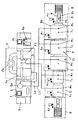
図1乃至図4は本発明の装置の実施の形態例を示し、大別すると、有機物が収納されたコンテナWを搬送可能な搬送部Aと、このコンテナWの搬送経路Rの手前側位置に配置された作動準備部Bと、コンテナWの搬送経路R中の作動準備部Bの後続位置に配置された加熱分解部Cと、コンテナWの搬送経路中の加熱分解部Cの後続位置に配置された冷却待機部Dと、加熱分解部Cに接続された分解ガス液化部Eと、分解ガス液化部Eに接続された排ガス処理部Fとから構成されている。
【0008】
ここに、上記搬送部Aは、有機物が収納されたコンテナWを作動準備部Bから加熱分解部Cを経て冷却待機部Dに至るまでの搬送経路Rにおいて搬送させる構造となっており、減速機付モータA1により駆動されるローラーコンベヤA2やチェーンコンベヤ等により構成され、特に、搬送部Aは、作動準備部B、加熱分解部C及び冷却待機部D毎に分離可能な内部搬送独立構造となっている。
【0009】
又、作動準備部Bは、コンテナWの搬送経路Rの手前側位置に配置されたコンテナ受入部B1及び空気と窒素ガスの入れ替え、即ち、窒素置換が行われる耐熱、断熱、閉鎖密閉構造のプリペレーション室B2と、予備加熱に使用する遠赤外線ヒータや電磁波を利用した加熱体B3とにより構成され、この窒素置換は窒素貯蔵ボンベTより複数個の窒素ガス注入管T1を介して窒素ガスをプリペレーション室B2に注入し、空気は排気管M1を介して強制的に室外へ排出することによりなされ、このプリペレーション室B2の入口部分及び加熱分解部Cに接続される出口部分に遮断扉Nが上下開閉機構N1のコンプレッサN2及びシリンダN3により開閉自在に配設され、しかして、プリペレーション室B1の遮断扉以外の上面、両側面及び底面に加熱体B3を配置し、かつ、この場合、コンテナ受入部B1とプリペレーション室B2とは、分離可能な独立構造となっている。
【0010】
又、加熱分解部Cは、コンテナWに収納されて搬送されてくる有機物を無酸素閉鎖密閉雰囲気下において低温間接加熱により熱分解可能な構造に構成され、複数個、この場合二個の加熱分解室C1・C1により構成され、このそれぞれの加熱分解室C1・C1にあっても、耐熱、断熱、閉鎖密閉構造に構成されると共に窒素貯蔵ボンベTより複数個の窒素ガス注入管T1を介して窒素ガスが注入され、室内の空気は排気管M1を介して強制的に室外へ排出され、又、加熱分解室C1・C1の間及び冷却待機部Dに接続される出口部分に遮断扉Nが上下開閉機構N1により開閉自在に配設され、加熱分解室C1・C1の遮断扉N以外の上面、両側面及び底面に加熱分解に使用する遠赤外線ヒータや電磁波を利用した加熱体C2を配置し、この場合加熱分解室C1・C1は相互に分離可能な独立構造となっている。
【0011】
又、冷却待機部Dは、コンテナW内の有機物が加熱分解部Cにより無酸素閉鎖密閉条件下において低温間接加熱により熱分解されて製造された炭素素材を冷却する冷却室D1と、搬出待機室D2とにより構成され、このそれぞれの冷却室D1及び搬出待機室D2にあっても、耐熱、断熱、閉鎖密閉構造に構成されると共に冷却室D1には窒素貯蔵ボンベTより複数個の窒素ガス注入管T1を介して炭素素材を冷却する窒素ガスが注入され、室内の空気は排気管M1を介して強制的に室外へ排出され、この場合、搬出待機室Dにも必要に応じて窒素ガスにより炭素素材を追加冷却可能に窒素ガス注入管T1が設けられ、室内の空気は排気管M1を介して強制的に室外へ排出され、又、冷却室D1と搬出待機室D2との間及び外につらなる出口部分に遮断扉Nが上下開閉機構N1により開閉自在に配設され、この場合、加熱分解室C1・C1と異なり、加熱体C2は配置されておらず、かつ、この場合冷却室D1と搬出待機室D2は相互に分離可能な独立構造となっている。
【0012】
又、分解ガス液化部Eは、冷却水タンクE1及び冷却塔E2からなり、この冷却塔E2内には分解ガスが通過する螺旋通気管が内蔵されると共にその周囲に冷却水が満たされ、冷却塔E2にドレン口が設けられている。
【0013】
又、排ガス処理部Fは、燃料ガスタンクF1及び二個の第一、第二排ガス燃焼室F2を備えてなり、燃料ガスタンクF1内のプロパンガス等により排ガス燃焼室F2内において排ガスを燃焼させて排ガス排出管F3より無臭、無害な排ガスを外に排出するように構成されている。
【0014】
この場合の管路系統にあっては、上記作動準備部Bのうちのプリペレーション室B2の排気管M1及び加熱分解部Cの二個の加熱分解室C1・C1の排気管M1は分解ガス液化部Eの冷却塔E2に管路L1により接続され、又、冷却待機部Dの冷却室D1及び搬出待機室D2は排ガス処理部Fの一方の第二排ガス燃焼室F2に管路L2により接続され、又、分解ガス液化部Eの冷却塔E2内の螺旋通気管の出口と排ガス処理部Fの他方の第一排ガス燃焼室F2に管路L3により接続されている。
【0015】
又、この場合、冷却待機部Dの搬出待機室D2の後続位置にコンテナ荷出部Gが配置されている。
【0016】
この実施の形態例は上記構成であるから、前処理作業として、有機物の種類や大きさにより圧潰や破砕を行うこともあり、この有機物が収納されたコンテナWは搬送部Aにより作動準備部Bから加熱分解部Cを経て冷却待機部Dに至る搬送経路Rに沿って搬送され、先ず、作動準備部Bにあって、このコンテナW内の有機物は耐熱、断熱、閉鎖密閉構造にして窒素置換により無酸素閉鎖密閉雰囲気としたプリペレーション室B2内において、加熱体B3により例えば360℃〜450℃程度の低温度条件で予備間接加熱され、次に、加熱分解部Cにあって、コンテナWの有機物は耐熱、断熱、閉鎖密閉構造にして窒素置換により無酸素閉鎖密閉雰囲気とした加熱分解室C1・C1内において、加熱体C2により、同じく、例えば360℃〜450℃程度の低温度条件で間接加熱され、これによりコンテナW内の有機物は熱分解されて炭素素材が製造され、次いで、冷却待機部Dにあって、コンテナWの炭素素材は耐熱、断熱、閉鎖密閉構造の冷却室D1内において、窒素ガスにより冷却され、搬出待機室D2において、取出待機することになり、そしてコンテナ荷出部Gより随時搬出される。必要に応じて、後処理作業として、磁選機により有機物と金属との分別作業を行うこともある。
【0017】
又、加熱分解部Cの加熱分解室C1・C1及びプリペレーション室B2内に発生したガスは分解ガス液化部Eにより液化され、排ガス処理部Fを介して外に排気され、又、冷却待機部Dの冷却室D1及び搬出待機部D2内のガスも排ガス処理部Fを介して外に排気されることになる。
【0018】
このようにして不用有機物を含む有機物を燃焼を伴わずに無酸素閉鎖密閉雰囲気下において低温間接加熱により熱分解させて炭素素材を製造することができ、生成炭素率が高く、炭素素材中の固定炭素量が75%以上のものも可能となって良質な炭素素材を製造することができ、しかも製造中の熱効率が非常に良く、悪臭や黒煙の大気中への排出も少なくすることができ、更に少数の人員で装置を稼働することができ、装置の耐用年数が長くなってメンテナンスも容易であり、又、連続的に炭素素材を製造することが可能であり作業能力も大きく、しかも有機物の粉砕や燃えるものと燃えないものとの分別作業などの前工程は必要なく、混在したまま用いることができる。
【0019】
ここに、無酸素閉鎖密閉雰囲気下での炭素化は製造された炭素素材を様々な用途に利用するためであり、不用有機物に混合しているであろう金属や無機物を取り除くことを容易にするためであり、またその金属等を再利用することも可能とする目的もある。金属は無酸素の状態であるので酸化はされず、間接加熱時の温度が360℃―450℃で低温のために金属の組成変化も起きず、更に無酸素状態での炭素化の折、生ガスが発生するが、この発生ガスも酸化されていないため、使用する原料の種類が、植物の場合は木酢、竹酢、草酢など良質なものを分解ガス液化部Eのドレン口より採取することができ、又、プラスチックやタイヤを原料とした場合に生成される炭素素材の他に熱分解させる時に発生する生ガスは分解温度設定の変更により、ナフサと同等の液体やA重油相当の液体を採取回収することができ、採取回収される液体の用途別に分解温度を変化させればよいのである。
【0020】
又、製造された炭素素材は炭素を含めて殆どが産業上の原料となるものであり、この炭素素材を産業上の原料として利用することにより、焼却場や埋立処分場の増設は必要最小限で良く、更には処分場に埋立てされている有機物を炭素化することにより、埋立処分場の延命もはかることができ、資源の浪費を防ぐこともできる。この焼却や埋立て処分されてきたものには、生ゴミや紙ゴミ、剪定枝、河川敷の雑草、道路脇の雑草、建築廃材、焼酎粕、ビール、ジュース、コーヒー粕、などがあり、またプラスチックは焼却の際に高発熱量のため焼却炉を痛めやすいことや有毒ガスが発生しやすいことなどからもっぱら埋立て処分されてきているが、これにより炭素素材を製造することにより、一つの資源を再度、再再度利用することになり、従って、炭素素材の製造という分野のみならず、産業廃棄物処理方法としても用いることができる。又、産業廃棄物の種類によっては、製造された炭素素材を殆ど利用できるものもあり、例えば、実施例として、現在廃棄されている紙おむつの場合では、焼却か埋立てであり、燃焼を伴うことになる焼却の際には高温と有害ガスが発生するし、焼却の過程で一次溶解し、塊となって燃焼の支えとする酸素源の供給口をふさぎ、装置の故障の原因を作り燃えにくくなる等が起きるが、上記の如く、熱分解することにすれば、紙おむつの中に混じり込んでいるであろうものはそのまま炭素化し、水分は蒸発し、紙おむつ本体も合成樹脂の部分は分解しガス化し、コットンなどは炭素化する。又、合成樹脂は分解ガス化する過程で一時的に溶解するが、燃焼工程における溶解と違い、熱が伝導するままに分解していく。焼却処理の場合は燃焼するために酸素が必要であり、また酸素と結合して燃焼が進むものであり、酸素と接触した部分のみが燃焼する。表面から順に燃焼が進む。すなわち、撹拌などの方法を用いらなければ燃焼時間の短縮は計れず、さらに酸素の供給のしかたによっては非常な高温になる場合もあるが、この方法にあっては、熱が伝わったところ、つまり分解するに必要な温度になった場合は、その温度になった場所から分解が進んで行き、空気などの対流が無くても分解は進み、溶解して塊になったとしても内部から分解が進む場合もあり、分解速度を焼却と比較して非常に早くできる。
【0021】
又、加熱分解部Cにおいて、有機物を熱分解させるための時間を消化するためと分解ガスの再利用の際の取り出し時期の決定、分解ガスの処理の時間、安全性、炭素化の程度の把握、管理の簡潔さ、メンテナンスの安易さなどを考慮し、更に作業能力に応じて複数個の加熱分解室C1を設けて構成され、又、搬送構造も各加熱分解室C1ごとに独立構造となっており、勿論この加熱分解室C1はそれぞれ密閉性、断熱、耐熱の構造であり、更に各加熱分解室ごとに分離できる構造とすることにより、修理などの際はその加熱分解室C1ごとに交換をするだけで良く修理による時間の浪費を無くして素早く対応することができ、また設置稼働後において、需要に応じて作業能力を増減させる場合は、この加熱分解室部C1の増減を行うだけで対応することができる。
【0022】
又、冷却待機部Dの冷却室D1は空気接触によっての燃焼を未然に防ぐために必要であり、窒素ガスによる急激な冷却は炭素の塊の中のミクロ気孔を発達させるために行うものであり、冷却の際に窒素ガスを使用することは炭素素材が乾燥した状態で取り出せるようにしたものであり、又、搬出待機室D2は炭素素材を再加工するために行うコンテナ荷出部G上の準備の完了を待つためと空気接触が起きても燃焼が起きない状態を確認するために設けてあり、冷却室D1同様に追加冷却可能に構成され、しかして、プリペレーション室B2、加熱分解室C1・C1、搬出待機室D2に至るまで外気に触れることなく無酸素の状態に保持するように構成している。
【0023】
又、搬送経路Rを通過する時間の設定は有機物の種類や再利用の方法によって決定することとし、又、装置一式を小型化し、車載化することにより原料発生場所、炭素素材の使用場所での炭素化も可能となり、機動力のある装置とすることが望ましく、これにより収集運搬費の軽減を図ることができる。
【0024】
尚、本発明は上記実施の形態例に限られるものではなく、搬送部A、作動準備部B、加熱分解部C、冷却待機部D、分解ガス液化部E及び排ガス処理部Fの構造や材質等は適宜変更して設計される。
【0025】
【発明の効果】
本発明は上述の如く、請求項1記載の発明にあっては、有機物を無酸素閉鎖密閉雰囲気下において低温間接加熱により熱分解させて炭素素材を製造することにより、産業廃棄物を含む有機物を原料として、固定炭素量の高い良質な炭素素材を製造することができ、しかも製造中の熱効率が非常に良く、悪臭や黒煙の大気中への排出も少なくすることができ、更に少数の人員で装置を稼働することができ、装置の耐用年数が長くなってメンテナンスも容易であり、又、連続的に炭素素材を製造することが可能であり作業能力も大きく、しかも有機物の粉砕や燃えるものと燃えないものとの分別作業などの前工程は必要なく、混在したまま用いることができ、焼却処理や埋立て処分していた廃棄物や、草木をも無駄無く利用することができるため資源の浪費を大幅に減少することができ、更に産業廃棄物の処理施設等の増設も必要なく、生成された炭素素材を産業上利用することにより多方面への経済効果が期待でき、資源保護にも大いに寄与することができる。
【0026】
又、請求項1記載の発明にあっては、上記加熱分解部は相互に分離可能な独立した複数個の加熱分解室により構成することにより、修理などの際はその加熱分解室ごとに交換をするだけで良く修理による時間の浪費を無くして素早く対応することができ、また設置稼働後において、需要に応じて作業能力を増減させる場合は、この加熱分解室部の増減を行うだけで対応することができる。
【0027】
以上所期の目的を充分達成することができる。
【図面の簡単な説明】
【図1】本発明の実施の形態例の全体説明平面図である。
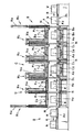
【図2】本発明の実施の形態例の部分説明側断面図である。
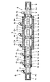
【図3】本発明の実施の形態例の部分説明平断面図である。
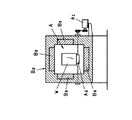
【図4】本発明の実施の形態例の部分説明横断面図である。
【符号の説明】
W コンテナ
R 搬送経路
A 搬送部
B 作動準備部
C 加熱分解部
C1 加熱分解室
D 冷却待機部
E 分解ガス液化部
F 排ガス処理部[0001]
BACKGROUND OF THE INVENTION
The present invention relates to an apparatus for producing a carbon material that becomes various industrial raw materials by, for example, industrial waste or vegetation planted in nature.
[0002]
[Prior art]
At present, various studies have been made on the reuse of waste organic matter including industrial waste, but most of it is still disposed of by incineration or landfill treatment.
[0003]
[Problems to be solved by the invention]
However, in these incineration treatments or landfill treatments, in recent years, a mixture of synthetic resins such as disposable diapers and pachinko machines and other organic or inorganic substances has been discharged in large quantities. Separation work is also required, and after the sorting work, incineration or landfill processing must be performed, which makes it difficult to handle, and it is also difficult to increase the number of incineration plants and secure a landfill site. It has become a big social problem.
[0005]
[Means for Solving the Problems]
The invention according to claim 1 includes a transport unit capable of transporting a container in which organic substances are stored, an operation preparation unit disposed at a position in front of the transport path of the container, and an operation in the transport path of the container. A thermal decomposition unit disposed at a subsequent position of the preparation unit, a cooling standby unit disposed at a subsequent position of the thermal decomposition unit in the transport path of the container, and a cracked gas liquefying unit connected to at least the thermal decomposition unit at least it and a said cracked gas liquefaction portion connected to the exhaust gas treatment unit, the pyrolysis unit is cold indirect heating of 360 ° C. to 450 ° C. in organic oxygen-free closure sealed atmosphere conveyed by the container In which the carbon material can be manufactured by pyrolysis, and nitrogen replacement is performed by injecting nitrogen gas into the operation preparation unit and forcibly discharging the air of the operation preparation unit. The decomposition section includes a nitrogen gas injection pipe for injecting nitrogen gas and an exhaust pipe for discharging the gas of the thermal decomposition section to the decomposition gas liquefaction section, and injects nitrogen gas from the nitrogen gas injection pipe into the heat decomposition section The oxygen-free closed sealed atmosphere is formed by nitrogen replacement for forcibly exhausting the air of the thermal decomposition unit through the exhaust pipe, and the thermal decomposition unit is separated into a plurality of independent thermal decomposition chambers. The cooling standby section is composed of a cooling chamber cooled by nitrogen gas injected with the carbon material conveyed in the container and an unloading standby chamber, and each heating of the operation preparation section and the thermal decomposition section cracking chamber及 beauty the cooling chamber of the cooling standby section and the unloading standby chamber is constructed in a closed sealed structure by each openable blocking doors, the transfer unit is the operation preparation unit, the thermal decomposition of the pyrolysis section Room and cold And separable independent structure for each stand portion, the first in the exhaust gas treatment unit comprises a second exhaust gas combustion chamber, introducing a gas from the decomposition gas liquefaction unit to said first exhaust gas combustion chamber, the cooling chamber and A configuration in which the gas from the carry-out standby chamber is introduced into the second exhaust gas combustion chamber, the gas is combusted in the first exhaust gas combustion chamber and the second exhaust gas combustion chamber, and discharged out of a common exhaust gas exhaust pipe; it is characterized in that the.
[0007]
DETAILED DESCRIPTION OF THE INVENTION
FIG. 1 to FIG. 4 show an embodiment of the apparatus of the present invention. Broadly speaking, the transport unit A capable of transporting a container W storing organic matter and a position on the near side of the transport path R of the container W are shown. Arranged at the operation preparation unit B arranged, the thermal decomposition unit C arranged at the subsequent position of the operation preparation unit B in the conveyance path R of the container W, and the subsequent position of the thermal decomposition unit C in the conveyance path of the container W The cooling standby section D, the cracked gas liquefying section E connected to the thermal decomposition section C, and the exhaust gas processing section F connected to the cracked gas liquefying section E are configured.
[0008]
Here, the transport unit A has a structure for transporting the container W in which organic substances are stored in the transport path R from the operation preparation unit B to the cooling standby unit D through the thermal decomposition unit C, and the speed reducer. Consists of a roller conveyor A 2 and a chain conveyor driven by the attached motor A 1 , and in particular, the transport section A is an internal transport independent structure that can be separated for each of the operation preparation section B, the thermal decomposition section C, and the cooling standby section D It has become.
[0009]
In addition, the operation preparation section B has a container receiving section B 1 arranged at a position on the near side of the transport path R of the container W, and replacement of air and nitrogen gas, that is, heat-resistant, heat-insulating, closed and sealed structure in which nitrogen replacement is performed. The preparation chamber B 2 and a far-infrared heater used for preheating and a heating body B 3 using electromagnetic waves are used. This nitrogen replacement is performed from a nitrogen storage cylinder T through a plurality of nitrogen gas injection pipes T 1. Nitrogen gas is injected into the preparation chamber B 2 , and the air is forcibly discharged to the outside through the exhaust pipe M 1 , and is connected to the inlet portion of the preparation chamber B 2 and the thermal decomposition section C. blocking door N to the exit portion is arranged to be freely opened and closed by a compressor N 2 and cylinder N 3 of the upper and lower closing mechanism N 1 heating, Thus, the upper surface other than the cut-off doors of prepared configuration chamber B 1, on both side surfaces and a bottom surface The body B 3 is arranged, and in this case, the container receiving part B 1 and the preparation chamber B 2 have a separable independent structure.
[0010]
In addition, the thermal decomposition unit C is configured to have a structure capable of thermally decomposing organic substances stored and transported in the container W by low-temperature indirect heating in an oxygen-free closed sealed atmosphere. is constituted by a chamber C 1 · C 1, even in the thermal decomposition chamber C 1 · C 1 of the respective heat, thermal insulation, a plurality of nitrogen gas inlet tube from the nitrogen storage cylinder T with configured in a closed sealed structure Nitrogen gas is injected through T 1 , and the indoor air is forcibly discharged to the outside through the exhaust pipe M 1 , and is connected between the thermal decomposition chambers C 1 and C 1 and the cooling standby section D. far infrared heater shut off the outlet portion door N is arranged to be freely opened and closed by upper and lower closing mechanism N 1, for use in heating exploded top non blocking door N of thermolysis chamber C 1 · C 1, both side and bottom surfaces that the heating element C 2 utilizing and electromagnetic arranged, in this case the heating component Chamber C 1 · C 1 has a mutually separable independent structure.
[0011]
The cooling standby section D includes a cooling chamber D 1 for cooling the carbon material produced by thermally decomposing the organic matter in the container W by low-temperature indirect heating under the oxygen-free closed sealed condition by the thermal decomposition section C, and a carry-out standby. is constituted by the chamber D 2, even in the respective cooling chambers D 1 and unloading standby chamber D 2, heat, insulation, more than nitrogen storage cylinder T is the cooling chamber D 1 with configured closed closed structure Nitrogen gas for cooling the carbon material is injected through the individual nitrogen gas injection pipes T 1 , and the indoor air is forcibly exhausted to the outside through the exhaust pipe M 1. A nitrogen gas injection pipe T 1 is provided so that the carbon material can be additionally cooled with nitrogen gas as required, and the indoor air is forcibly discharged outside through the exhaust pipe M 1 , and the cooling chamber D 1 Shut off at the exit part between and outside the unloading waiting room D 2 The door N is arranged to be opened and closed by a vertical opening / closing mechanism N 1. In this case, unlike the thermal decomposition chambers C 1 and C 1 , the heating body C 2 is not arranged, and in this case, the cooling chamber D 1 and unloading standby chamber D 2 has a mutually separable independent structure.
[0012]
The cracked gas liquefying section E is composed of a cooling water tank E 1 and a cooling tower E 2 , and a spiral ventilation pipe through which the cracked gas passes is built in the cooling tower E 2 and the surroundings are filled with cooling water. is a drain port is provided in the cooling tower E 2.
[0013]
The exhaust gas treatment section F includes a fuel gas tank F1 and two first and second exhaust gas combustion chambers F2, and the exhaust gas is burned in the exhaust gas combustion chamber F2 by propane gas or the like in the fuel gas tank F1. The exhaust pipe F3 is configured to discharge odorless and harmless exhaust gas to the outside.
[0014]
In the pipeline system in this case, the exhaust pipe M1 of the preparation chamber B2 and the exhaust pipe M1 of the two thermal decomposition chambers C1 and C1 of the thermal decomposition section C in the operation preparation section B are decomposed gas liquefaction. The cooling tower E2 of the part E is connected by a pipe L1, and the cooling chamber D1 and the unloading standby room D2 of the cooling standby part D are connected to one second exhaust gas combustion chamber F2 of the exhaust gas treatment part F by a pipe L2. The outlet of the spiral ventilation pipe in the cooling tower E2 of the cracked gas liquefying section E and the other first exhaust gas combustion chamber F2 of the exhaust gas processing section F are connected by a pipe L3.
[0015]
Further, in this case, the container Nide section G is disposed in a subsequent position of the unloading standby chamber D 2 of the cooling standby section D.
[0016]
Since this embodiment has the above-described configuration, it may be crushed or crushed according to the type and size of the organic matter as a pretreatment operation, and the container W storing the organic matter is moved by the transport unit A to the operation preparation unit B. Is transported along a transport path R from the thermal decomposition section C to the cooling standby section D. First, in the operation preparation section B, the organic matter in the container W is replaced with nitrogen in a heat-resistant, heat-insulating, closed and sealed structure. In the preparatory chamber B 2 having an oxygen-free closed hermetically sealed by the above, preliminary heating is performed by the heating body B 3 under a low temperature condition of about 360 ° C. to 450 ° C., for example. W of the organic material heat, thermal insulation, the nitrogen substitution in the closed sealed structure in an oxygen-free closed confined atmosphere and the thermal decomposition chamber C 1 · C 1, the heating element C 2, also, for example, 360 ° C. to 450 Indirect heating under low temperature conditions of about ℃, the organic matter in the container W is pyrolyzed to produce a carbon material, and then in the cooling standby part D, the carbon material of the container W is heat-resistant, heat-insulated and closed In the cooling chamber D 1 having a sealed structure, it is cooled by nitrogen gas, and in the unloading standby chamber D 2 , it is waiting for removal and is unloaded from the container unloading part G as needed. If necessary, as a post-processing operation, an organic substance and a metal may be separated by a magnetic separator.
[0017]
The gas generated in the thermal decomposition chambers C1 and C1 and the preparation chamber B2 of the thermal decomposition unit C is liquefied by the decomposition gas liquefaction unit E, exhausted outside through the exhaust gas processing unit F, and a cooling standby unit The gas in the cooling chamber D1 and the unloading standby part D2 of D is also exhausted to the outside through the exhaust gas processing part F.
[0018]
In this way, it is possible to produce carbon materials by pyrolyzing organic materials including unnecessary organic materials by low-temperature indirect heating in an oxygen-free closed sealed atmosphere without burning, and the generated carbon rate is high, and the carbon material is fixed in the carbon material. Carbon materials with a carbon content of 75% or more can be produced, and high-quality carbon materials can be produced. In addition, the thermal efficiency during production is very good, and the emission of bad odors and black smoke into the atmosphere can be reduced. In addition, the equipment can be operated by a small number of personnel, the service life of the equipment is extended, maintenance is easy, carbon materials can be continuously produced, work capacity is large, and organic matter There is no need for a pre-process such as pulverization or separation of burned and non-burned materials, and they can be used in a mixed state.
[0019]
Here, carbonization in an oxygen-free closed sealed atmosphere is to use the produced carbon material for various purposes, and it is easy to remove metals and inorganic substances that would have been mixed with unnecessary organic substances. Therefore, there is also an object to make it possible to reuse the metal or the like. Since the metal is in an oxygen-free state, it is not oxidized, the temperature during indirect heating is 360 ° C to 450 ° C, and the composition of the metal does not change due to the low temperature. Gas is generated, but this generated gas is not oxidized, so in the case of plants, good quality materials such as wood vinegar, bamboo vinegar, grass vinegar are collected from the drain port of the decomposition gas liquefaction unit E In addition to the carbon material produced when plastic or tires are used as raw materials, the raw gas generated when pyrolyzing is a liquid equivalent to naphtha or a liquid equivalent to heavy oil A by changing the decomposition temperature setting. Can be collected and recovered, and the decomposition temperature may be changed according to the use of the liquid collected and recovered.
[0020]
In addition, most of the produced carbon materials, including carbon, are industrial raw materials. By using these carbon raw materials as industrial raw materials, it is necessary to increase the number of incineration and landfill disposal sites. Furthermore, by carbonizing the organic matter landfilled at the disposal site, the life of the landfill disposal site can be prolonged and waste of resources can be prevented. This incinerated or landfilled waste includes raw garbage, paper waste, pruned branches, riverside weeds, roadside weeds, building waste, shochu, beer, juice, coffee grinders, and plastic Has been disposed of in landfills due to its high calorific value during incineration, which easily damages the incinerator and easily generates toxic gases. Therefore, it can be used again not only in the field of carbon material production but also as an industrial waste treatment method. Depending on the type of industrial waste, some of the produced carbon materials can be used. For example, in the case of disposable diapers that are currently disposed of, they are incinerated or landfilled, which involves combustion. During incineration, high temperatures and harmful gases are generated, and during the incineration process, primary melting takes place, and the oxygen source that supports the combustion is blocked by block, creating a cause of equipment failure and difficult to burn However, if thermal decomposition is performed as described above, what would be mixed in the paper diaper is carbonized as it is, the water evaporates, and the paper diaper body also decomposes the synthetic resin part. Gasification and cotton etc. are carbonized. In addition, the synthetic resin is temporarily dissolved in the process of decomposition and gasification, but unlike the dissolution in the combustion process, it is decomposed while the heat is conducted. In the case of incineration, oxygen is required for combustion, and the combustion proceeds by combining with oxygen, and only the portion in contact with oxygen burns. Combustion proceeds from the surface. In other words, if a method such as stirring is not used, the combustion time cannot be shortened, and depending on how oxygen is supplied, there may be a very high temperature, but in this method, when heat is transmitted, In other words, when the temperature reaches the temperature required for decomposition, the decomposition proceeds from the place where the temperature is reached, and the decomposition proceeds even without air or other convection. In some cases, the decomposition rate can be made much faster than incineration.
[0021]
In addition, in the thermal decomposition section C, to determine the time to take out the organic matter for thermal decomposition and to determine the extraction time when reusing the decomposition gas, the processing time of the decomposition gas, safety, and the degree of carbonization In consideration of the simplicity of management and ease of maintenance, a plurality of thermal decomposition chambers C 1 are provided according to the work capacity, and the transport structure is independent for each thermal decomposition chamber C 1. Of course, this pyrolysis chamber C 1 has a structure of hermeticity, heat insulation, and heat resistance, and can be separated for each thermal decomposition chamber. replacement can be be accommodated quickly eliminate the waste of time due to repair it is only the per, also after installation operation, when to increase or decrease the working capacity on demand, the thermal decomposition chamber C 1 Just increase or decrease Can.
[0022]
Further, the cooling chamber D1 of the cooling standby section D is necessary to prevent combustion due to air contact, and rapid cooling with nitrogen gas is performed to develop micropores in the carbon lump, the use of nitrogen gas during the cooling is obtained by the retrieval in the dry state is carbon material, also out antechamber D2 is prepared on the container Nide unit G performed to rework the carbon material It is provided to wait for completion of the process and to confirm that combustion does not occur even if air contact occurs, and is configured so that additional cooling is possible in the same manner as the cooling chamber D1, however, the preparation chamber B2 and the thermal decomposition chamber C1. -It is configured to keep oxygen-free without touching the outside air until C1 and the unloading standby chamber D2.
[0023]
In addition, the setting of the time to pass through the transport route R is determined by the type of organic matter and the method of reuse. Also, by reducing the size of the device and mounting it on the vehicle, the location where the raw material is generated and the location where the carbon material is used Carbonization is also possible, and it is desirable to use a mobile device, which can reduce collection and transportation costs.
[0024]
In addition, this invention is not restricted to the said embodiment, The structure and material of the conveyance part A, the operation preparation part B, the thermal decomposition part C, the cooling standby part D, the decomposition gas liquefaction part E, and the exhaust gas treatment part F Etc. are designed with appropriate changes.
[0025]
【The invention's effect】
The invention as described above, in the first aspect of the present invention, by organic matter is thermally decomposed by the low-temperature indirect heating in an oxygen-free closed confined atmosphere to produce a carbon material, an organic material comprising industrial wastes A high-quality carbon material with a high fixed carbon content can be produced as a raw material, and the heat efficiency during production is very good. The emission of bad odors and black smoke into the atmosphere can be reduced, and a smaller number of personnel The equipment can be operated with a long service life of the equipment, maintenance is easy, the carbon material can be continuously produced, the work capacity is large, and organic matter is pulverized or burned Because there is no need for pre-processes such as separation work from non-combustible materials, they can be used as they are mixed, and waste and vegetation that has been incinerated or landfilled can be used without waste. The waste of resources can be greatly reduced, and there is no need to add industrial waste treatment facilities. The industrial use of the generated carbon material can be expected to produce economic benefits in many fields, and resource conservation. Can also contribute greatly.
[0026]
In the invention described in claim 1 , the thermal decomposition section is constituted by a plurality of independent thermal decomposition chambers that are separable from each other, so that each thermal decomposition chamber can be replaced for repair. It is possible to respond quickly without wasting time due to repair, and if the work capacity is increased or decreased according to demand after installation and operation, it can be handled by simply increasing or decreasing the thermal decomposition chamber. be able to.
[0027]
As described above, the intended purpose can be sufficiently achieved.
[Brief description of the drawings]
FIG. 1 is an overall explanatory plan view of an embodiment of the present invention.
FIG. 2 is a partial cross-sectional side view of an embodiment of the present invention.
FIG. 3 is a partial cross-sectional plan view of an embodiment of the present invention.
FIG. 4 is a partial cross-sectional view for explaining an embodiment of the present invention.
[Explanation of symbols]
W Container R Transport path A Transport section B Operation preparation section C Thermal decomposition section C 1 Thermal decomposition chamber D Cooling standby section E Decomposed gas liquefying section F Exhaust gas processing section
Claims (1)
上記作動準備部には窒素ガスを注入して該作動準備部の空気を強制的に排出する窒素置換が行われ、
上記加熱分解部には窒素ガスを注入する窒素ガス注入管と、該熱分解部のガスを前記分解ガス液化部に排出する排気管を備え、該窒素ガス注入管から窒素ガスを該加熱分解部に注入し、該加熱分解部の空気を該排気管を介して強制的に排出する窒素置換によって上記無酸素閉鎖密閉雰囲気を形成し、
上記加熱分解部は相互に分離可能な独立した複数の加熱分解室により構成され、
上記冷却待機部は上記コンテナで搬送されてくる炭素素材を注入される窒素ガスによって冷却する冷却室と搬出待機室とにより構成され、
上記作動準備部、上記加熱分解部の各加熱分解室及び上記冷却待機部の上記冷却室と上記搬出待機室は、各々開閉可能な遮断扉により閉鎖密閉構造に構成され、
上記搬送部は上記作動準備部、上記加熱分解部の各加熱分解室及び上記冷却待機部ごとに分離可能な独立構造とし、
上記排ガス処理部に第一、第二排ガス燃焼室を備え、上記分解ガス液化部からのガスを該第一排ガス燃焼室に導入し、上記冷却室及び上記搬出待機室からのガスを該第二排ガス燃焼室に導入し、該第一排ガス燃焼室と該第二排ガス燃焼室にてガスを燃焼させて共通の排ガス排出管より外に排出する構成としたことを特徴とする炭素素材の製造装置。A transport unit capable of transporting a container storing organic matter, an operation preparation unit disposed at a position in front of the container transport path, and a heating disposed at a position subsequent to the operation preparation unit in the container transport path. A decomposition unit, a cooling standby unit disposed at a position subsequent to the heating decomposition unit in the transport path of the container, at least a decomposition gas liquefaction unit connected to the heating decomposition unit, and at least connected to the decomposition gas liquefaction unit An exhaust gas treatment unit is provided, and the pyrolysis unit can produce a carbon material by pyrolyzing the organic matter transported in the container by low-temperature indirect heating at 360 ° C. to 450 ° C. in an oxygen-free closed sealed atmosphere. Structured to
Nitrogen replacement is performed to forcibly exhaust the air of the operation preparation unit by injecting nitrogen gas into the operation preparation unit,
The thermal decomposition section includes a nitrogen gas injection pipe for injecting nitrogen gas, and an exhaust pipe for discharging the gas of the thermal decomposition section to the cracked gas liquefying section, and the nitrogen gas is supplied from the nitrogen gas injection pipe to the thermal decomposition section. The oxygen-free closed sealed atmosphere is formed by nitrogen replacement forcibly exhausting the air of the thermal decomposition section through the exhaust pipe,
The thermal decomposition part is composed of a plurality of independent thermal decomposition chambers that can be separated from each other,
The cooling standby unit is composed of a cooling chamber that cools the carbon material that is transported in the container by nitrogen gas injected and a carry-out standby chamber,
The operation preparation unit, the thermal decomposition chamber of the pyrolysis unit 及 beauty the cooling chamber of the cooling standby section and the unloading standby chamber is constructed in a closed sealed structure by each openable blocking doors,
The transport unit has an independent structure that can be separated for each of the operation preparation unit, each thermal decomposition chamber of the thermal decomposition unit, and the cooling standby unit,
The exhaust gas treatment unit includes first and second exhaust gas combustion chambers, gas from the cracked gas liquefaction unit is introduced into the first exhaust gas combustion chamber, and gas from the cooling chamber and the carry-out standby chamber is supplied to the second exhaust gas combustion chamber. An apparatus for producing a carbon material, characterized in that it is introduced into an exhaust gas combustion chamber and combusted in the first exhaust gas combustion chamber and the second exhaust gas combustion chamber and discharged outside a common exhaust gas exhaust pipe .
Priority Applications (2)
| Application Number | Priority Date | Filing Date | Title |
|---|---|---|---|
| JP28359496A JP3946292B2 (en) | 1996-10-25 | 1996-10-25 | Carbon material production equipment |
| TW086114928A TW345503B (en) | 1996-10-25 | 1997-10-13 | Production of carbon material and device therefor |
Applications Claiming Priority (1)
| Application Number | Priority Date | Filing Date | Title |
|---|---|---|---|
| JP28359496A JP3946292B2 (en) | 1996-10-25 | 1996-10-25 | Carbon material production equipment |
Publications (2)
| Publication Number | Publication Date |
|---|---|
| JPH10130007A JPH10130007A (en) | 1998-05-19 |
| JP3946292B2 true JP3946292B2 (en) | 2007-07-18 |
Family
ID=17667532
Family Applications (1)
| Application Number | Title | Priority Date | Filing Date |
|---|---|---|---|
| JP28359496A Expired - Fee Related JP3946292B2 (en) | 1996-10-25 | 1996-10-25 | Carbon material production equipment |
Country Status (2)
| Country | Link |
|---|---|
| JP (1) | JP3946292B2 (en) |
| TW (1) | TW345503B (en) |
Families Citing this family (8)
| Publication number | Priority date | Publication date | Assignee | Title |
|---|---|---|---|---|
| JP3621053B2 (en) * | 2000-06-21 | 2005-02-16 | 株式会社エイティ−ン・パートナーズ | Waste treatment system and waste carbonization method |
| ES2378148T3 (en) * | 2002-07-25 | 2012-04-09 | Kunimichi Sato | Resource recycling system and system |
| AU2002368188A1 (en) * | 2002-08-26 | 2004-03-11 | Mamoru Itoh | Method and device for producing carbon material |
| KR100473763B1 (en) * | 2002-09-28 | 2005-03-10 | 천지득 | Recycling machine of waste tire for oil, carbon and wire core by auto continuous process |
| JP5277370B2 (en) * | 2006-11-17 | 2013-08-28 | 廣太郎 土本 | Continuous heating furnace for carbonization of organic waste |
| JP2008222901A (en) * | 2007-03-14 | 2008-09-25 | Kayaba System Machinery Kk | Carbonizer |
| JP2009144120A (en) * | 2007-12-18 | 2009-07-02 | Ss Kenkyusho:Kk | Treatment device and treatment method for organic solid waste |
| WO2018070031A1 (en) * | 2016-10-14 | 2018-04-19 | 鈴木 利昭 | Compositional separation type carbonization system |
-
1996
- 1996-10-25 JP JP28359496A patent/JP3946292B2/en not_active Expired - Fee Related
-
1997
- 1997-10-13 TW TW086114928A patent/TW345503B/en not_active IP Right Cessation
Also Published As
| Publication number | Publication date |
|---|---|
| TW345503B (en) | 1998-11-21 |
| JPH10130007A (en) | 1998-05-19 |
Similar Documents
| Publication | Publication Date | Title |
|---|---|---|
| CN106482117A (en) | Domestic garbage pyrolysis processing method and processing device | |
| JP3946292B2 (en) | Carbon material production equipment | |
| KR20140016451A (en) | Pyrolysis apparatus | |
| CN105385465B (en) | Garbage pyrolysis device and method | |
| CN104987871A (en) | Household garbage miniature continuous type self-heating movable horizontal dry distillation machine | |
| CN109052889A (en) | Indirect heating packaged type industrial sludge continuous pyrolysis method and carbonizing plant | |
| CN115875678B (en) | A kitchen waste in-situ pyrolysis vehicle | |
| WO2007014489A1 (en) | A pyrolysis method for treating waste rubber and plastics and materials containing resins | |
| CN107781824A (en) | A kind of high-efficiency low-pollution rural garbage method of disposal and its device | |
| US11111439B1 (en) | Microwave apparatus for pyrolyzing carbonaceous material and related method | |
| CH720234A2 (en) | An energy-efficient pyrolysis system for the treatment of solid organic waste | |
| KR101964127B1 (en) | Method for manufacturing low carbon composite free and eco-friendly material using waste railroad wood sleeper, and heating generating multistage equipment micro-wave with indirect heating mode for the same | |
| CN116947281B (en) | Method for pyrolyzing and deodorizing sludge by using tunnel kiln | |
| FR2654112A1 (en) | METHOD AND PLANT FOR TREATING URBAN AND / OR INDUSTRIAL WASTE. | |
| ES2243132B1 (en) | PROCESS FOR RECYCLING OF RUBBER OF RUBBER IN DISPOSAL, INSTALLATION TO CARRY OUT IT. | |
| CN112032735A (en) | A mobile garbage disposal system and method using gas powered vehicles | |
| NZ253249A (en) | Generating electricity from combustible gas produced by compressed and heated waste materials | |
| WO1998053251A1 (en) | A method and apparatus for recovering energy of waste classification incineration | |
| JPH05185056A (en) | Method and device for processing waste composite plastics | |
| KR100853557B1 (en) | Continuous carbonization method and equipment of concentrated organic waste using petroleum decomposition products as fuel | |
| KR100492670B1 (en) | An apparatus for carbonizing the domestic waste by thermal decomposition | |
| CN212227043U (en) | Solid hazardous waste resource utilization system | |
| WO2004018591A1 (en) | Method and device for producing carbon material | |
| CN112393247B (en) | Low-temperature thin-layer rapid thermal gradient anaerobic pyrolysis system and solid waste pyrolysis system based on same | |
| JP2007216204A (en) | Waste pyrolysis equipment |
Legal Events
| Date | Code | Title | Description |
|---|---|---|---|
| A711 | Notification of change in applicant |
Free format text: JAPANESE INTERMEDIATE CODE: A712 Effective date: 20050314 |
|
| A521 | Request for written amendment filed |
Free format text: JAPANESE INTERMEDIATE CODE: A821 Effective date: 20050316 |
|
| A977 | Report on retrieval |
Free format text: JAPANESE INTERMEDIATE CODE: A971007 Effective date: 20050902 |
|
| A131 | Notification of reasons for refusal |
Free format text: JAPANESE INTERMEDIATE CODE: A131 Effective date: 20060613 |
|
| A521 | Request for written amendment filed |
Free format text: JAPANESE INTERMEDIATE CODE: A523 Effective date: 20060814 |
|
| A131 | Notification of reasons for refusal |
Free format text: JAPANESE INTERMEDIATE CODE: A131 Effective date: 20061024 |
|
| A521 | Request for written amendment filed |
Free format text: JAPANESE INTERMEDIATE CODE: A523 Effective date: 20061225 |
|
| TRDD | Decision of grant or rejection written | ||
| A01 | Written decision to grant a patent or to grant a registration (utility model) |
Free format text: JAPANESE INTERMEDIATE CODE: A01 Effective date: 20070313 |
|
| A61 | First payment of annual fees (during grant procedure) |
Free format text: JAPANESE INTERMEDIATE CODE: A61 Effective date: 20070411 |
|
| R150 | Certificate of patent or registration of utility model |
Free format text: JAPANESE INTERMEDIATE CODE: R150 |
|
| A711 | Notification of change in applicant |
Free format text: JAPANESE INTERMEDIATE CODE: A711 Effective date: 20070405 |
|
| R154 | Certificate of patent or utility model (reissue) |
Free format text: JAPANESE INTERMEDIATE CODE: R154 |
|
| FPAY | Renewal fee payment (event date is renewal date of database) |
Free format text: PAYMENT UNTIL: 20100420 Year of fee payment: 3 |
|
| FPAY | Renewal fee payment (event date is renewal date of database) |
Free format text: PAYMENT UNTIL: 20100420 Year of fee payment: 3 |
|
| FPAY | Renewal fee payment (event date is renewal date of database) |
Free format text: PAYMENT UNTIL: 20100420 Year of fee payment: 3 |
|
| R360 | Written notification for declining of transfer of rights |
Free format text: JAPANESE INTERMEDIATE CODE: R360 |
|
| FPAY | Renewal fee payment (event date is renewal date of database) |
Free format text: PAYMENT UNTIL: 20100420 Year of fee payment: 3 |
|
| R370 | Written measure of declining of transfer procedure |
Free format text: JAPANESE INTERMEDIATE CODE: R370 |
|
| FPAY | Renewal fee payment (event date is renewal date of database) |
Free format text: PAYMENT UNTIL: 20100420 Year of fee payment: 3 |
|
| FPAY | Renewal fee payment (event date is renewal date of database) |
Free format text: PAYMENT UNTIL: 20100420 Year of fee payment: 3 |
|
| FPAY | Renewal fee payment (event date is renewal date of database) |
Free format text: PAYMENT UNTIL: 20100420 Year of fee payment: 3 |
|
| FPAY | Renewal fee payment (event date is renewal date of database) |
Free format text: PAYMENT UNTIL: 20110420 Year of fee payment: 4 |
|
| FPAY | Renewal fee payment (event date is renewal date of database) |
Free format text: PAYMENT UNTIL: 20110420 Year of fee payment: 4 |
|
| FPAY | Renewal fee payment (event date is renewal date of database) |
Free format text: PAYMENT UNTIL: 20120420 Year of fee payment: 5 |
|
| FPAY | Renewal fee payment (event date is renewal date of database) |
Free format text: PAYMENT UNTIL: 20120420 Year of fee payment: 5 |
|
| R350 | Written notification of registration of transfer |
Free format text: JAPANESE INTERMEDIATE CODE: R350 |
|
| S111 | Request for change of ownership or part of ownership |
Free format text: JAPANESE INTERMEDIATE CODE: R313113 |
|
| FPAY | Renewal fee payment (event date is renewal date of database) |
Free format text: PAYMENT UNTIL: 20120420 Year of fee payment: 5 |
|
| S111 | Request for change of ownership or part of ownership |
Free format text: JAPANESE INTERMEDIATE CODE: R313113 |
|
| R350 | Written notification of registration of transfer |
Free format text: JAPANESE INTERMEDIATE CODE: R350 |
|
| FPAY | Renewal fee payment (event date is renewal date of database) |
Free format text: PAYMENT UNTIL: 20130420 Year of fee payment: 6 |
|
| FPAY | Renewal fee payment (event date is renewal date of database) |
Free format text: PAYMENT UNTIL: 20130420 Year of fee payment: 6 |
|
| FPAY | Renewal fee payment (event date is renewal date of database) |
Free format text: PAYMENT UNTIL: 20140420 Year of fee payment: 7 |
|
| R250 | Receipt of annual fees |
Free format text: JAPANESE INTERMEDIATE CODE: R250 |
|
| R250 | Receipt of annual fees |
Free format text: JAPANESE INTERMEDIATE CODE: R250 |
|
| LAPS | Cancellation because of no payment of annual fees |