JP3937543B2 - Image forming apparatus - Google Patents
Image forming apparatus Download PDFInfo
- Publication number
- JP3937543B2 JP3937543B2 JP35906497A JP35906497A JP3937543B2 JP 3937543 B2 JP3937543 B2 JP 3937543B2 JP 35906497 A JP35906497 A JP 35906497A JP 35906497 A JP35906497 A JP 35906497A JP 3937543 B2 JP3937543 B2 JP 3937543B2
- Authority
- JP
- Japan
- Prior art keywords
- toner
- color
- transfer
- intermediate transfer
- roller
- Prior art date
- Legal status (The legal status is an assumption and is not a legal conclusion. Google has not performed a legal analysis and makes no representation as to the accuracy of the status listed.)
- Expired - Fee Related
Links
Images


Classifications
-
- G—PHYSICS
- G03—PHOTOGRAPHY; CINEMATOGRAPHY; ANALOGOUS TECHNIQUES USING WAVES OTHER THAN OPTICAL WAVES; ELECTROGRAPHY; HOLOGRAPHY
- G03G—ELECTROGRAPHY; ELECTROPHOTOGRAPHY; MAGNETOGRAPHY
- G03G15/00—Apparatus for electrographic processes using a charge pattern
- G03G15/01—Apparatus for electrographic processes using a charge pattern for producing multicoloured copies
- G03G15/0105—Details of unit
- G03G15/0131—Details of unit for transferring a pattern to a second base
-
- G—PHYSICS
- G03—PHOTOGRAPHY; CINEMATOGRAPHY; ANALOGOUS TECHNIQUES USING WAVES OTHER THAN OPTICAL WAVES; ELECTROGRAPHY; HOLOGRAPHY
- G03G—ELECTROGRAPHY; ELECTROPHOTOGRAPHY; MAGNETOGRAPHY
- G03G2215/00—Apparatus for electrophotographic processes
- G03G2215/01—Apparatus for electrophotographic processes for producing multicoloured copies
- G03G2215/0167—Apparatus for electrophotographic processes for producing multicoloured copies single electrographic recording member
- G03G2215/0174—Apparatus for electrophotographic processes for producing multicoloured copies single electrographic recording member plural rotations of recording member to produce multicoloured copy
- G03G2215/0177—Rotating set of developing units
Landscapes
- Physics & Mathematics (AREA)
- General Physics & Mathematics (AREA)
- Color Electrophotography (AREA)
- Electrostatic Charge, Transfer And Separation In Electrography (AREA)
Description
【0001】
【発明の属する技術分野】
本発明は、第1の像担持体上に形成したトナー像を、第2の像担持体を介して転写材に転写する方式の画像形成装置に関する。
【0002】
【従来の技術】
従来、電子写真方式のカラーの画像形成装置において、感光ドラム等の第1の像担持体の他に、中間転写体等の第2の像担持体を備えたものが知られている。このものは、第1の像担持体上に形成したトナー像を一旦、第2の像担持体上に転写するいわゆる一次転写を複数回繰り返して第2の像担持体上に複数色のトナー像を重ねた後、これら複数色のトナー像を紙等の転写材上に一括して二次転写するものである。
【0003】
図6に、第2の像担持体として中間転写ベルト(中間転写体)を使用した画像形成装置の一例を示す。
【0004】
同図に示す画像形成装置は、第1の像担持体として感光ドラム101を備えている。矢印R1方向に回転自在に支持された感光ドラム101の周囲には、各色のトナー、すなわちブラック(BK)、シアン(C)、マゼンタ(M)、イエロー(Y)の4色のトナーがそれぞれ収納された4個の現像器105、106、107、108が配置されている。これらの現像器のうち、感光ドラム101上の静電潜像の現像に供されるものが、接離手段(不図示)によって感光ドラム101に当接するように構成されている。
【0005】
感光ドラム101は、帯電器102によって一様に帯電され、レーザー露光光学系103等による走査光(レーザー光)104によって静電潜像が形成される。次に、静電潜像は、前述の現像器105等によりトナーが付着されてトナー像として現像され、順次に第2の像担持体としての中間転写ベルト(中間転写体)109上に一次転写ローラ110によって一次転写ニップ部N1 を介して一次転写される。上述の静電潜像の形成、現像、一次転写が4色のトナーについて現像器108、107、106、105等によってY、M、C、BKの順に順次に行われ、これにより、中間転写ベルト109上に4色重ねのカラーのトナー像が形成される。次いで、これらトナー像は、二次転写ローラ111と中間転写ベルト109との間に形成される二次転写部位N2 にて狭持搬送される転写材118に一括して二次転写される。
【0006】
上述の一次転写、及び二次転写について更に詳述する。まず、感光ドラム101が、例えば負の帯電特性を有するOPC(有機光半導体)感光体である場合、レーザー光104における露光部を現像器105〜108で現像する際には負極性トナーが用いられている。したがって、一次転写ローラ110にはバイアス電源120により正極性の転写バイアスが印加される。
【0007】
ここで、中間転写ベルト109は、一例として、厚さ100〜300μm程度の無端状の樹脂ベルトを、体積抵抗率1011〜1016Ω・cm程度に抵抗調整したものを用いることができる。この場合、樹脂ベルトの材質としては、例えば、PVdF(ポリフッ化ビニリデン)、ナイロン、PET(ポリエチレンテレフタレート)、ポリカーボネート等の樹脂フィルム(必要に応じて抵抗調整がなされている)等を用いることができる。また、別の例として、上記樹脂ベルトをカーボン、ZnO、SnO2 、TiO2 、その他の導電性の充填材により107 〜1011Ω・cm程度の体積抵抗値に調整して用いる場合もある。後者のように低〜中抵抗化を図ることで、中間転写ベルト109に電荷が蓄積することによる画像不良を防止できる。
【0008】
さらに、別の例として、中間転写ベルト109の材質として、樹脂よりも低硬度の厚さ0.5〜2mm程度のゴム材(クロロプレンゴム、EPDM、NBR、ウレタンゴム等)を、体積抵抗率106 〜1011Ω・cm程度に調整して用いることもできる。
【0009】
これらの中間転写ベルト109は、背面ローラ112、駆動ローラ115、テンションローラ116等に掛け渡されている。一次転写ローラ110としては、体積抵抗率が105 Ω・cm以下の低抵抗ローラを用いることが一般的である。なお、以上においては、一次転写ローラ110とバイアス電源120とによって一次転写手段を構成している。
【0010】
次に、二次転写ローラ111、背面ローラ112、バイアス電源121等によって構成された二次転写手段によって転写材118に対するトナー像の二次転写を行う。二次転写は、中間転写ベルト109の内側に、接地又は適当なバイアスを印加した低抵抗の背面ローラ112を対向電極として配置し、これと外側に配置した低抵抗の二次転写ローラ111とで中間転写ベルト109を挟み込んで二次転写ニップ部N2 を構成し、二次転写ローラ111に対してバイアス電源121によって正極性の転写バイアスを印加しこの二次転写ローラ111を転写材118の裏面側から当接させることによって行う。
【0011】
上述の一次転写が終了した感光ドラム101は、表面に残った一次転写残トナーがクリーナ119によって除去回収され、さらに残留電荷が露光器117によって除去されて、次の画像形成に供される。
【0012】
一方、上述の二次転写が終了した中間転写ベルト109は、クリーナ113によって、転写材118に転写されないで中間転写ベルト109上に残った二次転写残トナーが除去された後、必要に応じて除電帯電器(除電手段)114によって除電される。除電帯電器114としては、ACコロナ帯電を用いることが多い。また、除電効率を上げるため、中間転写ベルト109の内側に電極を設けるのが一般的である。
【0013】
なお、上記除電帯電器114は、前述のような低〜中抵抗の中間転写ベルト109の使用時においては省略することも可能である。
【0014】
なお、中間転写体としては、上述の中間転写ベルト109の他に中間転写ローラもあるが、一般に、中間転写ベルト109は、この中間転写ローラに比べて、配置の自由度の高さ、二次転写後の転写材118の分離性の良さ(曲率分離が可能)という点において優れている。
【0015】
一方、中間転写ローラは、中間転写ベルトがベルトを駆動するのに比べ、構造を単純化することができる。なお、この中間転写ローラの場合でも筒体の表面に設ける樹脂又はゴム層の電気的特性を、中間転写ベルトの場合と同様に考えればよいので、詳細な説明は省略する。
【0016】
上記のような装置において、4色のトナーY、M、C、BKの画像形成順序は、従来、Y、M、Cの3色を任意の順で形成し、最後にBKを形成するようにしている。
【0017】
これは、中間転写方式以前の方式である多重転写方式、すなわち、回転ドラム上に紙等の転写材を巻き付けて固定し、その転写材上に感光体から順次転写を繰り返す方式の頃から一般的に行われている方法であり、他色に比べ、BK(黒)は文字等の情報が多いため、BKを1〜3色目に一次転写してしまうと、それ以降の色を一次転写する際に感光体にBKが逆戻りしてしまう、いわゆる再転写による黒トナーの損失が生じる可能性があり、これを原理的に無くするための習慣的な方法である。このため、二次転写により転写材118上にトナーを写し取った後は、BKトナーが最下層(転写材表面に最も近い層)となる。
【0018】
【発明が解決しようとする課題】
上述の従来例では、以下のような問題点があった。すなわち、感光ドラム101から中間転写ベルト109上にカラートナー像を順次に一次転写する際に、一旦、中間転写ベルト109上に転写された1色目のトナーは、2〜4色目のトナーが順次転写される間は中間転写ベルト109上に保持され続けるが、このとき、2〜4色目のトナー転写時において1色目のトナーと、感光ドラム1又は中間転写ベルト109との間で電荷の授受が行われ、4色目のトナーの一次転写終了時点においては、1色目のトナーの有する電荷(トリボ)が1色目の一次転写時点での電荷と異なってしまう。この結果、一次転写終了後における、中間転写ベルト上の1〜4色目のトナー、特に1色目と4色目のトナーの二次転写条件が異なり、前記の例においては、二次転写ローラ111のバイアス値を、1色目のYの転写効率の良い値に合わせると4色目のBKが、また、逆に4色目のBKに合わせると1色目のYが二次転写不良を生じたり、転写効率の低下により色味が変化するなどの問題があった。
【0019】
これを防止するために、一次転写〜二次転写間において、直流又は交流のコロナ帯電器122を用い、1〜4色目のトナーのトリボを、中間転写ベルト上で二次転写前にほぼ同じ値に再帯電する、いわゆるポスト帯電を行う方法が考えられるが、この方法は、装置構成の複雑化、高コスト化等の問題があり、また、中間転写ベルト109上に形成された1〜4色のトナーのトリボを均一にならすのが難しく、例えば中間調のハイライト(淡い)部分に画像ムラを生じるなどの問題があった。
【0020】
さらにまた、中間転写ベルト109上に残留した二次転写残トナーを、クリーナ113等を用いずに、適当な帯電状態に再帯電した上で、一次転写ニップ部N1 を介して感光ドラム101に回収(逆転写)する、という方法が既に考案されているが、これをクリーニングのための特別な回転を行わず、次プリント(次画像形成)の1色目の一次転写時に行う場合、この1色目の転写バイアスが高いと、上記回収が良好に行われないという問題があった。しかし、一般に、非磁性のカラートナーを用いた場合、トナーの帯電電荷量が高く、このため一次転写バイアス値を上記クリーニング条件に合わせて低下させると一次転写効率が低下してしまうという問題が生じていた。
【0021】
本発明は、上述の事情に鑑みてなされたものであり、装置構成を複雑にすることなく、転写不良の防止、転写効率の向上、画像ムラの防止を行うことができる画像形成装置を提供することを目的とするものである。
【0022】
【課題を解決するための手段】
上記の目的を達成するための、請求項1に係る発明は、中間転写体と、前記中間転写体に複数色のトナーを順次重ねて形成する像形成手段とを有し、前記中間転写体上の複数色のトナーは転写材上へ転写される画像形成装置において、前記中間転写体上に転写された最初の色のトナーの単位重量あたりの飽和帯電量は、前記最初の色の次色以降のトナーの単位重量あたりの飽和帯電量よりも小さく、前記中間転写体上に最終色のトナーが転写された後、前記中間転写体上の前記複数色のトナーが転写材上に転写される前において、前記中間転写体上に形成された前記複数色のトナーのうち前記最終色のトナーと異なる色のトナーの単位重量あたりの帯電電荷量が、前記最終色のトナーの単位重量あたりの帯電電荷量の0.5〜1.5倍となるように、前記像形成手段が前記異なる色のトナーを帯電することを特徴とする。
【0023】
請求項2に係る発明は、請求項1に記載の画像形成装置において、前記像形成手段は、トナーを担持する像担持体と、前記像担持体上にトナーを形成する現像手段と、を有し、前記現像手段上の最初の色のトナーのトナーの単位重量あたりの帯電電荷量は、前記最初の色の次色以降のトナーの単位重量あたりの帯電電荷量よりも小さいことを特徴とする。
【0030】
〔作用〕
上述のように、1色目のトナーの帯電電荷量を、最終色のトナーの帯電電荷量の0.5〜1.5倍の電荷量とすることで、転写材上に対するトナー像の二次転写を良好に行うことができる。
【0031】
また、一次転写時の1色目のトナーの帯電電荷量が、一次転写時の2色目以降のトナーの帯電電荷量よりも小さくなるように設定することで、二次転写後における二次転写残トナーの第1の像担持体への回収(逆転写)が容易となる。
【0032】
【発明の実施の形態】
以下、図面に沿って、本発明の実施の形態について説明する。
【0033】
〈実施の形態1〉
図1は、本発明に係る画像形成装置の実施の形態1における概略構成を示す図であり、まず、同図に基づいて、画像形成装置全体の構成及び動作の概略を説明する。
【0034】
同図に画像形成装置は、4色フルカラーの画像形成装置であり、主要構成部材(手段)として、次の1〜7の各部材(手段)、すなわち第1の像担持体1と、顕像形成手段2、3、4と、第2の像担持体5と、第1の転写手段6と、第2の転写手段7とを備えている。そして、これら主要構成部材(手段)に基づく動作の概要は、第1の像担持体1上に顕像形成手段2、3、4によって顕像を形成し、この顕像を第1の転写手段6によって一旦、第2の像担持体5上に一次転写し、その後、この第2の像担持体5上の顕像を第2の転写手段7によって紙等の転写材P上に転写するものである。以下、順に詳述する。
【0035】
同図に示す第1の像担持体1は、ドラム型の電子写真感光体(以下「感光ドラム1」という)である。感光ドラム1は、アルミニウム製の円筒状の基体と、その表面を覆う例えばOPC(有機光半導体)感光層とによって構成されており、駆動手段(不図示)によって矢印R1方向に回転駆動される。
【0036】
顕像形成手段は、帯電手段2、露光手段3、現像手段4等によって構成されている。帯電手段2は、感光ドラム1に接触配置された帯電ローラ21とこれに帯電バイアスを印加する電源(不図示)とを備えている。本実施の形態1では、この電源により、帯電ローラ21を介して感光ドラム1表面をマイナス極性の均一な電位に帯電している。
【0037】
露光手段3は、レーザー光学系31を備えており、画像情報に基づいたレーザー走査光32によって、感光ドラム1表面を露光し、露光部分の電荷を除去して静電潜像形成する。
【0038】
現像手段4は、回転可能な回転体41と、これに搭載された4個の現像器、すなわちブラック(黒)、イエロー、マゼンタ、シアンの各色の現像剤(トナー)をそれぞれ収納した現像器4B、4Y、4M、4Cを備えている。これら現像器のうち、感光ドラム1上の静電潜像の現像に供される色の現像器が、回転体41の矢印R4方向への回転によって感光ドラム1表面に対向する現像位置に配置されることになる。これら4個の現像器は、同様に構成されており、黒の現像器4Bを例に説明すると、回転可能な現像スリーブ4aと、この表面にトナーを塗布する塗布ローラ4bと、現像スリーブ4a表面上のトナーの層厚を規制する弾性ブレード4c等を有し、トナー収納容器4d内の一成分非磁性ネガトナーの電荷付与及び現像スリーブ4aへの均一コーティングを行い、そして、感光ドラム1に対して現像スリーブ4aが相対的に負になるような現像バイアスが印加されることで、感光ドラム1上の静電潜像に黒のトナーを付着させて、反転現像を行っている。
【0039】
第2の像担持体5は、中間転写ベルト(中間転写ベルト)51を主要構成部材として構成されている。中間転写ベルト51は、厚さ0.5〜2mmの可撓性のベルト部材を基体として無端状(エンドレス)に形成したものであり、駆動ローラ52、従動ローラ53、後述の二次対向ローラ72等に掛け渡されて、矢印R5方向に回転駆動される。中間転写ベルト51は、その表面(外周面)側に配置された前述の感光ドラム1と、裏面(内周面)側に配置された後述の一次転写ローラ61とによって狭持されており、中間転写ベルト51表面と感光ドラム1表面との間には、一次転写ニップ部(第1の転写部位)N1が感光ドラム1表面の母線に沿って帯状に形成されている。
【0040】
第1の転写手段6は、感光ドラム1と対向する位置において、中間転写ベルト51の裏面に接触配置された一次転写ローラ61と、これに一次転写バイアスを印加する転写バイアス電源62とを備えている。上述の感光ドラム1上に形成された黒のトナー像は、転写バイアス電源62によって一次転写ローラ61に+300〜500V程度の一次転写バイアスを印加することで、中間転写ベルト51上に一次転写される。一次転写後の感光ドラム1は、表面に残った一次転写残トナーがクリーナ8のクリーニングブレード81によって掻き落とされて除去されることでクリーニングされ、次のシアンの画像形成に供される。
【0041】
上述の帯電、露光、現像、一次転写、クリーニングからなる一連の画像形成プロセスを他の3色、すなわち、イエロー、マゼンタ、シアン、についても行い、これにより、中間転写ベルト51上には、4色のトナー像が重なるようにして形成される。このとき、一次転写バイアスは、例えば+400V、+600V、+700V、+800Vというように1色目から4色目にかけて順次上昇させる。
【0042】
第2の転写手段7は、中間転写ベルト51の表面側に配置された二次転写ローラ71と、裏面側に配置された二次対向ローラ72とを備えており、これら2つのローラ71、72によって中間転写ベルト51を狭持して、二次転写ローラ71表面と中間転写ベルト51との間に帯状の二次転写ニップ部(第2の転写部位)N2 を構成している。二次転写ローラ71には、これに二次転写バイアスを印加する転写バイアス電源73が接続されており、また二次対向ローラ72はフロート状態としてある。上述の中間転写ベルト51上に一次転写された4色分のトナー像は、転写バイアス電源73によって、二次転写ローラ71に二次転写バイアスを印加することで、紙等の転写材P上に一括して二次転写される。
【0043】
二次転写後の中間転写ベルト51は、ファーブラシ96(又はブレード等でも良い)を有するクリーニング手段95により、転写材Pに転写されないで表面に残った二次転写残トナーが清掃された後、表面に残った残留電荷が除電手段9によって除電される。除電手段9は、除電ローラ91を有し、矢印K9方向に移動可能なハウジング92と中間転写ベルト51を挟んでこれと対向して配置された補助ローラ93とを有する。クリーニング手段95とともにハウジング92を矢印K9方向に移動させて除電ローラ91と補助ローラ93との間に中間転写ベルト51を挟み込み、クリーニングバイアス電源94にて所定のバイアス電圧を印加することで、中間転写ベルト51表面の二次転写残トナー、及び残留電荷を除去し、初期化する。なお、上述の除電が非コロナ帯電である、接触帯電手段により可能となるのは、後述のように中間転写ベルト51の基層に低抵抗ゴムを用いたことによる効果の一つである。
【0044】
一方、上述の第2の転写手段7によって4色のトナー像が二次転写された転写材Pは、矢印KP 方向に搬送され、定着装置(不図示)によって加熱加圧されて、表面にトナー像が定着された後、画像形成装置本体の外部に排出される。
【0045】
なお、上述の画像形成プロセスにおいて、プロセススピードvP は、vP =10.0cm/秒に設定されており、また、転写材Pは、転写材搬送手段(不図示)によって矢印KP 方向に給送される。
【0046】
次に、第2の像担持体5、第2の転写手段7、除電手段9について詳述する。
【0047】
中間転写ベルト51は、無端状に形成した基層51a上にコート層を設けて構成されており、基層としては、カーボン、酸化チタン、酸化スズ等の添加によって体積抵抗率が1×10⁴ Ω・cm程度に調整されるとともに、硬度がJIS−A測定法でほぼ60度のNBR(ニトルリゴム)、EPDM(エチレンプロピレンゴム)等を素材とし、これを厚さ1mm、幅220mm、周長が約140πmmの円筒状にシームレス成型したものを用いた。なお、成型法としては、一例として、押出し成型した2枚のゴム材の間に補強のための芯糸を挟み、加硫することで伸縮の少ない高強度の基層を得ることができる。
【0048】
基層上に設ける高抵抗のコート層としては、ウレタン系バインダーにテフロン等の離型剤を分散させたものを用い、厚さが約50μm程度となるようにコートを行った。コーティング法としてはスプレーコート、ディッピング、その他の方法を用いることができる。コート層のコート材料の抵抗値はウレタン材料の中から、体積抵抗率として、約1012〜1016Ω・cm程度のものを取捨選択して用いた。
【0049】
次に、第2の転写手段7について説明する。
【0050】
第2の転写手段7における二次転写ローラ71は、硬度が約40度(アスカーC測定法による)、体積抵抗率が約104 Ω・cmの発泡EPDMのゴムローラを用いた。この他に低抵抗のウレタン系ゴム、クロロプレンゴム、NBR等を用いてもよい。また、転写バイアス電源73には約+1000〜+2000Vの電圧を印加し、通紙時において10μA程度の転写電流が流れるように調整を行った。
【0051】
除電手段9は、除電ローラ91として、帯電ローラ21と同様の材質のものを用いた。帯電ローラ21は周知の接触帯電方式によるもので、例えば、厚さ3mm程度の弾性導電ゴム上に100〜200μm、体積抵抗率106 Ω・cm程度の中抵抗層を設け、さらにその上に数10μmの固着防止層(ナイロン系樹脂等)を設けて構成する。除電電圧としては、クリーニングバイアス電源94によって、ピーク間電圧VPPが約3kVのAC電圧に、+100〜+1000V程度のDC電圧を重畳したバイアス電圧を印加し、対向の補助ローラ93は一次転写ローラ61と同電位とした。
【0052】
次に、本実施の形態に用いた現像剤について説明する。
【0053】
現像剤としては、各色ともポリエステル系樹脂を母体に用いた、非磁性一成分ネガトナーを使用した。詳細については、例えば、特願平4−152219号に記載されている。
【0054】
すなわち、トナーの結着樹脂が、下記成分(a)、(b)、(c)、及び(d)を少なくとも含有する単量体組成物から生成されたポリエステル樹脂を主成分として含有し、該ポリエステル樹脂の水酸基価が10〜20であり、重畳平均分子量が13000〜20000であり、数平均分子量が5000〜8000であり、重畳平均分子量(Mw)/数平均分子量(Mn)の比が2〜3.5であるようなトナーである。
【0055】
(a)イソフタル酸、テレフタル酸及びその誘導体より選ばれた2価の芳香族系酸成分を全モノマー量の25〜35mol%、
(b)トリメリット酸及びその誘導体より選ばれた3価の芳香族系酸成分を全モノマー量の2〜4mol%、
(c)ドデセニルコハク酸、オクチルコハク酸及びその無水物より少なくとも選ばれた2価の酸成分を全モノマー量の12〜18mol%、
(d)プロボキシ化、又は/及びエトキシ化したエーテル化ジフェノール成分を全モノマー量の45〜60mol%。
【0056】
上記トナー母体を、適宜着色剤により着色し、混合、混練の後、粉砕、分級工程を経て直径ほぼ4〜8μmのトナー分級品を得た。この分級品の100重量部に対し、荷電制御剤として、ジメチルシリコーンオイル処理を行ったシリカを1〜2重量部加えて混合し、ネガ極性に帯電する非磁性一成分系カラートナーを製造した。このとき、1色目に一次転写を行う黒トナーに関しては、その母体に、トナーの電荷保持能力を緩和するために、リークサイトとしてカーボンを3〜5重量部程度添加した後、混合、混練、粉砕、分級の工程を経てトナー分級品を得た。
【0057】
上記トナーの現像スリーブ4a上における帯電電荷量(以下「トリボ」という)を直接トナーを吸引し、その際に流れる電流値及び吸引されたトナー量より算定したところ、黒トナーはほぼ−18μC/g、Y、M、Cの各色のトナーはほぼ−30μC/g程度であった。なお、これらの値は、温度23℃、相対湿度60%の環境下で測定したものである。
【0058】
次に、上記トナーを用いて中間転写ベルト51上にトナー像を形成し、中間転写ベルト51上でのトナーのトリボを測定した。図2に、1〜4色目の一次転写終了後における黒トナーのトリボを、本発明の場合を(A)、従来例(比較例)の場合、すなわち、着色剤として微量のカーボンブラックを用いる以外は、リークサイトとしてのカーボンを混合・混練していない従来トナーの場合を(B)として図示する。なお、同図において、領域Sは、4色目のトナーであるCトナーが、二次転写を良好に行えるように二次転写バイアス値を設定したときの、二次転写効率が許容範囲内となるトナートリボの領域を示すものである。本実験においては、二次転写バイアス値をほぼ+1500Vとし、二次転写効率は85%以上となることを基準にして領域Sを決定した。この結果、領域Sは下限が約−16μC/g、上限が約−48μC/gであり、一方、4色目のCトナーの、中間転写ベルト51での一次転写後の帯電量は約−32μC/gであった。すなわち、4色すべての一次転写終了後における中間転写ベルト51上のトナーは、4色目のトナーのトリボに対し、約0.5倍〜1.5倍の範囲内にトリボが入っていれば、二次転写が良好に行えるということになる。これに対し、図2では、本発明においては、トナー内のリークサイトの作用により、4回の一次転写後においても1色目の黒トナー帯電量は領域S内であるのに対し、従来のトナーでは2〜4色目の一次転写時に1色目の黒トナーが感光ドラム1からマイナスの電荷を付与されて次第にトリボが増し、4色目の一次転写後においては、ついに領域Sの外へ出てしまい、二次転写を良好に行うことができなくなっている。このように、本発明の場合(A)においてトリボの増加が少なく、次第に頭打ちとなるのは、トナー内のリークサイトの作用により、トナーの飽和帯電量が従来トナーのそれよりも低く抑えれられているためである。これは、図2において、黒トナーの曲線Aが、4回転でほぼ飽和状態となっていることから知ることができる。このように、本実施の形態のように一次転写を繰り返すうちにトナーのトリボが上昇していく系において、1色目のトナーの飽和帯電量を他色のそれよりも低目にすることにより、4回の一次転写後に引き続き行われる二次転写性を向上し、すべての色について良好な一括二次転写を行うための転写マージンを拡大することが可能となる。
【0059】
なお、2、3色目のトナーについても、4色目のトナーに対し、二次転写前における中間転写ベルト51上でのトリボが0.5〜1.5倍の範囲とするのがよい。ただし、本実施の形態において説明したように、1色目に比べ、2〜3色目のトナーはその後の4色目までの一次転写時において、感光ドラム1との一次転写ニップ部N1 にて電荷を得る機会が少ないため、本実施の形態のように2〜4色目のトナーの飽和帯電特性や現像スリーブ上トリボなどはほぼ同じとしてもよい。もちろん、必要に応じて2色目、又は3色目のトナーの上記特性を若干調整してもよい。また、各トナーの飽和帯電量は、簡易的には上記の一次転写を複数回(4〜10回転位)行うことで測定できる。本実施の形態では、黒トナーはほぼ25μC/g程度で飽和したのに対し、Y、M、Cのトナーではほぼ60μC/gにて飽和状態に達した。もちろん、この他に、他の適切な測定法(例えば磁性粉体を用いてトナーを帯電し、帯電電荷を測定する方法など)を用いることができる。
【0060】
なお、本実施の形態においては、黒トナーを1色目としたが、このことはリークサイトとしてカーボン等を用いる場合、材料の色が合っており、この点では黒トナーを用いるのが、好適である。なお、本実施の形態のように、黒トナーの飽和帯電量を下げた系においては、従来懸念されていた2〜4回目の一次転写時における黒トナーの感光ドラム1への逆転写も生じることがなかった。しかも、BK(黒)、Y、M、Cの淡い中間調部分の二次転写性も非常に良好であった。
【0061】
〈実施の形態2〉
本発明の実施の形態2として、黒トナーには磁性一成分系ネガ現像剤、Y、M、Cの色トナーには重合法による非磁性一成分系ネガ現像剤を用いた例を示す。
なお、装置構成に関しては実施の形態1とぼ同一のものを用い、詳細説明は省略する。
【0062】
まず、黒トナーについて、トナー分給品の材料を以下の構成とした。
【0063】

【0064】
この分級品100重量部にジメチルシリコーンオイル処理したシリカを1.2重量部加えて混合して、ネガ極性に帯電する一成分系絶縁性磁性トナーを得た。
【0065】
一方、黒トナー用の現像器としては、図1の現像器4Bにおいて、現像スリーブ4aの内部に固定マグネットを配置し、感光ドラム1との対向部分においてトナーに対し磁力による拘束力を与えている。なお、本実施の形態では弾性ブレード4cによるトナーへの摺擦のみ行い、塗布ローラ4bは除去するという構成にてトナーへのトリボ付与と現像スリーブ4aへの均一コーティングを行った。
【0066】
次に、Y、M、Cの色トナーについては、シャープメルトトナーの中にあらかじめ離型剤として溶融粘度と分子量がトナー母体樹脂より小さいワックス、パラフィン等の離型剤を内添した重合法によるトナーを使用した。これにより、高い混色性を達成し、かつ定着時には熱によりトナーからワックスがはみ出し、定着装置として一般に用いられる熱ローラ定着装置(不図示)の離型効果を高めた構成でのオイルレス化を達成している。
【0067】
上記重合トナーは、その製造法上、ほぼ球形となる。その球形形状のうち、最内部のコア部分として、本実施の形態ではエステル系ワックスを内包し、その外側に樹脂層としてスチレン−アクリレート、さらにその外側(表層)にスチレン−ポリエステル、という構成の重合トナーを用いた。
【0068】
その比重は約1.05である。3層構成となっている理由は、コアにワックスを内包することで、定着工程でのオフセット防止効果が得られ、また表層に樹脂層を設けることによって帯電効率のアップを図ることができるからであり、また実際に使用時には、トリボ安定化のためにオイル処理したシリカを外添している。
【0069】
重合法としては、本実施の形態においては、比較的容易に粒度分布がシャープで4〜8μm粒径の微粒子トナーが得られる常圧下での、又は加圧下での懸濁重合方法(特公昭36−10231号公報、特開昭59−53856号公報、特開昭59−61842号公報等に記載されている懸濁重合方法等を参照)を用い、モノマーとしてスチレンとn−ブチルアクリレート、荷電制御剤としてサリチル酸金属化合物、極性レジンとして飽和ポリエステル、さらに着色剤を加え、重量平均粒径7μmの着色懸濁粒子を製造した。
【0070】
なお、トナー粒度分布制御や粒径の制御は、難水溶性の無機塩や保護コロイド作用を有する分散剤の種類や添加量を変える方法や機械的装置条件、例えばローラの周速、パス回数、攪拌羽根形状等の攪拌条件や、容器形状又は水溶液中での固形分濃度等を制御することにより所定の本実施の形態のトナーを得ることができる。
【0071】
上記トナーの着色剤としては、以下のようなものを用いることができる。すなわち、イエロー着色剤としては、縮合アゾ化合物、イソインドリノン化合物、アンスラキノン化合物、アゾ金属錯体、メチン化合物、アリルアミド化合物に代表される化合物が用いられる。
【0072】
マゼンタ着色剤としては、縮合アゾ化合物、ジケトピロロピロール化合物、アンスラキノン、キナクリドン化合物、塩基染料レーキ化合物、ナフトール化合物、ベンズイミダゾロン化合物、チオインジゴ化合物、ペリレン化合物が用いられる。
【0073】
シアンの着色剤としては、銅フタロシアニン化合物及びその誘導体、アンスラキノン化合物、塩基染料レーキ化合物等が利用できる。
【0074】
なお、上記Y、M、Cの各トナー用現像器としては、実施の形態1にて説明を行った図1の現像器4Y、4M、4C、(及び4B)とほぼ同一構造のものを用いたので説明を省略する。
【0075】
上記のトナーの現像スリーブ4a上におけるトリボを、直接トナーを吸引し、その際に流れる電流値及び吸引されたトナー量より算定したところ、磁性トナーである黒トナーはほぼ−10μC/gであるのに対し、Y、M、Cの各色のトナーはほぼ−30μC/g程度であった。なお、これらの値は温度23℃、湿度60%の環境下で測定したものである。
【0076】
次に、上記トナーを用いて中間転写ベルト51上にトナー像を形成し、中間転写ベルト51上でのトナーのトリボを測定した。本実施の形態においても、トナーの現像順は、実施の形態1と同様にB、Y、M、Cの順に行った。このとき、各色の一次転写バイアス値はそれぞれ+150V、+600V、+700V、+800Vが最適な値であった。1色目の黒が実施の形態1よりも小さいのは現像スリーブ4a上の黒トナーのトリボが低いためである。
【0077】
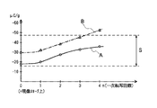
図3に、1〜4色目の一次転写終了後における黒トナーのトリボ(実線A)、及び、比較例として1色目に本実施の形態のM(マゼンタ)トナーを用いた場合のトリボ(一点鎖線B)の変化を示す。なお、本実施の形態においても、図2と同様、領域Sは4色目のトナーであるCトナーが二次転写を良好に行えるように二次転写バイアス値を設定したときの、二次転写効率が許容範囲内(ほぼ85%以上)となるトナートリボの領域を示すものである。本実施の形態においても、二次転写バイアス値をほぼ+1500Vとしたとき、領域Sの広さは最大となり、このときのトリボの下限は約−16μC/g、上限は約−48μC/gであった。これに対し、図3では、黒トナーは実線Aのように一次転写直後であるn=1回転目では、二次転写が適正に行われるためのトリボ下限である−16μC/gには達しておらず、n=4回転目には二次転写のための良好なトリボ値に十分達している(図3ではほぼ−25μC/g)。
【0078】
一方、比較のためのMトナーによる一点鎖線Bでは、次第にトナーのトリボが上昇し、n=4回転目にはトリボがほぼ−53μC/gに達し、上限−48μC/gを超えてしまっている。すなわち、本実施の形態においては、1色目の黒トナー、2色目以降に他のトナーを用いることで良好な結果が得られ、一方、1色目に黒以外のトナーを用いると二次転写時に1色目がトリボ過剰による転写不良を、また、4色目に黒トナーを用いると、二次転写時に4色目がトリボ不足による転写不良や飛び散りを生じてしまう。
【0079】
これは、本実施の形態で用いた黒トナーに含まれる磁性体(四三酸化鉄)が電荷のリークサイトとして作用し、トナーの帯電性能や飽和帯電量を他の重合法による非磁性のY、M、Cトナーよりも大幅に低く抑えられているためである。したがって、従来のようにY、M、C、Bなどの順で、B(黒)トナーを最終色とすると二次転写時にトナーのトリボが揃わず、二次転写前にポスト帯電(図6の122)等を行う必要が生じるが、本実施の形態ように、B(黒)トナーを1色目とすることにより、二次転写までの間に黒トナーのトリボが高められ、ポスト帯電を用いずに良好な二次転写を行うことができる。つまり、磁性トナーと非磁性トナーという、トリボの大幅に異なるトナーの混在系においても、本実施の形態によれば二次転写を良好に行うことが可能となる。
【0080】
〈実施の形態3〉
図4に実施の形態3を示す。本実施の形態は、実施の形態1における中間転写ベルト51のクリーニング手段95を除去し、代わりに、除電手段9を用いて、二次転写後の中間転写ベルト51上の二次転写残トナーを逆帯電(すなわち本実施の形態においてはプラス帯電)させ、感光ドラム1に回収させるものである。
【0081】
上記条件を満足させるためには、帯電ローラ91に印加するクリーニングバイアス電源94の電圧として、除電のためのACバイアス(ほぼ2〜3kVPP、1〜3kHz程度)、及び、二次転写残トナーをプラスに帯電させるためのDCバイアス(対向ローラ72に印加させる二次転写バイアス値に対し、0〜+500V程度高いバイアス)を重畳して印加すればよいことが、例えば、特願平8−208646号公報に記載されている。
【0082】
一方、感光ドラム1に対し、プラスに逆帯電された二次転写残トナーが回収されるために、感光ドラム1の表面電位と一次転写ローラ61のバイアス電圧値との関係が所定の範囲内である必要がある。具体的には、本実施の形態の構成においては、プラスに帯電されたトナーが負電位の感光ドラム1に回収されるためには、感光ドラム1の表面電位をVS (V)、一次転写バイアス値をVT1(V)とすると、ΔV=VS −VT1が、−200〜−800Vの範囲内である必要がある。すなわち、ΔVの絶対値が200Vより小さいと、プラストナーが感光ドラム1に吸引されず、逆に絶対値が800Vより大きいと、図5に示すように感光ドラム1と中間転写ベルト51とによって構成される一次転写ニップN1 近傍における、感光ドラム1の回転方向についての上流側において、感光ドラム1と中間転写ベルト51間で気中放電が発生してしまい、この結果、一次転写ニップ部N1 直前で中間転写ベルト51及び中間転写ベルト51上の二次転写残トナーT+ が負極性に帯電されてしまうため(負極性に帯電された二次転写残トナーをT- で図示)、二次転写残トナーT- が感光ドラム1に回収されなくなってしまう。
【0083】
感光ドラム1の表面電位VS は、本実施の形態において、暗部がほぼ−600V、明部がほぼ−100Vであるから、上記のようなクリーニングのための条件を満足するには、クリーニングと同時に次プリントの1色目の一次転写を行う場合、この1色目の一次転写バイアス値は+100〜+200Vの範囲でなければならない(+100V以下では明部に二次転写残トナーが回収されず、+200V以上では暗部に対して気中放電が発生し、やはり二次転写残トナーが回収されない)。
【0084】
このように、一次転写と同時に二次転写残トナーを回収するためには、1色目の一次転写に課される条件が厳しいものとなる。
【0085】
このような場合において、実施の形態1、又は実施の形態2で説明したトナーのうち、例えばY、M、Cのトナーでは、現像スリーブ4a上のトリボが約−30μC/gと大きく、したがって、これらのトナーを1色目に配すると、上記クリーニングのための条件である、一次転写バイアス値+100V〜+200Vでは転写バイアスが小さいため、十分な転写効率が得られなかった。これに対し、実施の形態1又は実施の形態2で説明したようにリークサイトにより飽和帯電量を減じたトナー(この場合、黒トナー)を用いると、+100V〜+200Vの一次転写バイアス値で十分な転写を行うことが可能となる。本実施の形態では、実施の形態2のトナー(Y、M、Cは重合法によるトナー、B(黒)は磁性トナー)を用い、一次転写を行う順を黒、B、M、C、Yの順とし、それぞれの一次転写バイアス値を+150V、+600V、+700V、+800Vとした。この結果、実施の形態2において説明したのと同様にそれぞれのトナーが二次転写時において適切なトリボに調整され、良好な二次転写を行うことができ、しかも、次工程である次プリントの1色目の一次転写と同時に前工程での二次転写時に中間転写ベルト51上の時に転写残トナーの、感光ドラム1への回収を容易に行うことができた。これにより、図4に示すように、図1におけるクリーニング手段95等を使用しない簡易な構成でありながら、本実施の形態では、連続プリント時においても、中間転写ベルト51の回転数N、プリント枚数Pの関係をN=4×Pとすることができ、クリーニングのための余分な回転を必要としない分、スループットを向上させることができた。
【0086】
なお、本実施の形態では、B、M、C、Yの順に画像形成をおこなったが、B、Y、M、C、又はまたはその他の順であってもよく、1色目に飽和帯電量の低いトナーを配することで上記クリーニング同時一次転写を容易に行うことができる。
【0087】
以上、本発明の実施の形態1〜3について説明を行ったが、いずれの実施の形態においても、第2の像担持体(中間転写体)として中間転写ベルト51を使用するに代えて、中間転写ドラムを使用した場合においても、上述と同様の効果をあげることができる。
【0088】
【発明の効果】
以上説明したように、本発明によると、一次転写を第2の像担持体上に繰り返し行った後、第2の像担持体上において、1色目のトナーのトリボと4色目のトナーのトリボとの差を小さくしておくことで、二次転写が良好に行えるようになった。
【図面の簡単な説明】
【図1】実施の形態1の画像形成装置の概略構成を示す縦断面図。
【図2】実施の形態1における、一次転写回数とトナートリボとの関係を示す図。
【図3】実施の形態2における、一次転写回数とトナートリボとの関係を示す図。
【図4】実施の形態3の画像形成装置の概略構成を示す縦断面図。
【図5】気中放電によって二次転写残トナーが負極性に帯電されるようすを示す図。
【図6】従来の画像形成装置の概略構成を示す縦断面図。
【符号の説明】
1 第1の像担持体(感光ドラム)
2 帯電手段
3 露光手段
4 現像手段
5 第2の像担持体(中間転写体)
6 第1の転写手段
7 第2の転写手段
9 除電手段
21 転写ローラ
51 中間転写ベルト
61 一次転写残トナー
62 転写バイアス電源
71 二次転写ローラ
72 転写バイアス電源
94 クリーニングバイアス電源
95 クリーニング手段
N1 第1の転写部位(一次転写ニップ部)
N2 第2の転写部位(二次転写ニップ部)
P 転写材[0001]
BACKGROUND OF THE INVENTION
The present invention relates to an image forming apparatus that transfers a toner image formed on a first image carrier to a transfer material via a second image carrier.
[0002]
[Prior art]
2. Description of the Related Art Conventionally, an electrophotographic color image forming apparatus is known that includes a second image carrier such as an intermediate transfer member in addition to a first image carrier such as a photosensitive drum. In this toner, a toner image formed on the first image carrier is temporarily transferred to the second image carrier, so-called primary transfer is repeated a plurality of times, and a plurality of color toner images are formed on the second image carrier. Then, the toner images of the plurality of colors are collectively transferred onto a transfer material such as paper.
[0003]
FIG. 6 shows an example of an image forming apparatus using an intermediate transfer belt (intermediate transfer member) as the second image carrier.
[0004]
The image forming apparatus shown in FIG. 1 includes a
[0005]
The
[0006]
The above-described primary transfer and secondary transfer will be described in further detail. First, when the
[0007]
Here, as an example, the
[0008]
As another example, a rubber material (chloroprene rubber, EPDM, NBR, urethane rubber, etc.) having a thickness lower than that of the resin and having a hardness of about 0.5 to 2 mm is used as the material of the
[0009]
These
[0010]
Next, the secondary transfer of the toner image onto the
[0011]
The primary transfer residual toner remaining on the surface of the
[0012]
On the other hand, the
[0013]
The neutralizing
[0014]
As the intermediate transfer member, there is an intermediate transfer roller in addition to the above-described
[0015]
On the other hand, the structure of the intermediate transfer roller can be simplified as compared with the case where the intermediate transfer belt drives the belt. Even in the case of this intermediate transfer roller, the electrical characteristics of the resin or rubber layer provided on the surface of the cylindrical body can be considered in the same manner as in the case of the intermediate transfer belt, and thus detailed description thereof is omitted.
[0016]
In the apparatus as described above, the image forming order of the four color toners Y, M, C, and BK is conventionally formed in any order in three colors of Y, M, and C, and finally BK is formed. ing.
[0017]
This is common since the multiple transfer method, which is a method before the intermediate transfer method, that is, a method in which a transfer material such as paper is wound around a rotating drum and fixed, and the transfer is repeated sequentially from the photosensitive member onto the transfer material. Since BK (black) has more information such as characters compared to other colors, if BK is first transferred to the first to third colors, the subsequent colors are transferred first. In addition, there is a possibility that black toner may be lost due to so-called retransfer, in which BK returns to the photoconductor, which is a customary method for eliminating this in principle. For this reason, after the toner is copied onto the
[0018]
[Problems to be solved by the invention]
The conventional example described above has the following problems. That is, when the color toner images are sequentially transferred from the
[0019]
In order to prevent this, a DC or
[0020]
Furthermore, after the secondary transfer residual toner remaining on the
[0021]
The present invention has been made in view of the above circumstances, and provides an image forming apparatus capable of preventing transfer failure, improving transfer efficiency, and preventing image unevenness without complicating the apparatus configuration. It is for the purpose.
[0022]
[Means for Solving the Problems]
In order to achieve the above object, an invention according to
[0023]
According to claim 2The image forming apparatus according to
[0030]
[Action]
As described above, the charge amount of the first color toner is set to 0.5 to 1.5 times the charge amount of the final color toner, so that the toner image is secondarily transferred onto the transfer material. Can be performed satisfactorily.
[0031]
Further, by setting the charged charge amount of the first color toner at the time of primary transfer to be smaller than the charged charge amount of the second color and subsequent toners at the time of primary transfer, the secondary transfer residual toner after the secondary transfer Recovery (reverse transfer) to the first image carrier becomes easy.
[0032]
DETAILED DESCRIPTION OF THE INVENTION
Hereinafter, embodiments of the present invention will be described with reference to the drawings.
[0033]
<
FIG. 1 is a diagram showing a schematic configuration in
[0034]
The image forming apparatus shown in FIG. 1 is a four-color full-color image forming apparatus. As main constituent members (means), the following members (means) 1 to 7, that is, the
[0035]
A
[0036]
The visible image forming unit includes a
[0037]
The exposure means 3 includes a laser
[0038]
The developing means 4 includes a rotatable rotating
[0039]
The
[0040]
The
[0041]
The above-described series of image forming processes including charging, exposure, development, primary transfer, and cleaning is performed for the other three colors, that is, yellow, magenta, and cyan, so that four colors are formed on the
[0042]
The
[0043]
The
[0044]
On the other hand, the transfer material P on which the four color toner images are secondarily transferred by the second transfer means 7 described above is indicated by an arrow K.P Then, the toner image is fixed on the surface by being heated and pressed by a fixing device (not shown), and then discharged to the outside of the image forming apparatus main body.
[0045]
In the above image forming process, the process speed vP Is vP = 10.0 cm / sec. Further, the transfer material P is moved by the arrow K by the transfer material conveying means (not shown).P Fed in the direction.
[0046]
Next, the
[0047]
The
[0048]
As the high-resistance coating layer provided on the base layer, a urethane binder having a release agent such as Teflon dispersed therein was used, and the coating was performed so that the thickness was about 50 μm. As the coating method, spray coating, dipping, and other methods can be used. The resistance value of the coating material of the coating layer is approximately 10 as a volume resistivity among urethane materials.12-1016Those of about Ω · cm were selected and used.
[0049]
Next, the second transfer means 7 will be described.
[0050]
The
[0051]
The neutralizing means 9 is made of the same material as the charging
[0052]
Next, the developer used in this embodiment will be described.
[0053]
As the developer, non-magnetic one-component negative toner using a polyester resin as a base material for each color was used. Details are described in, for example, Japanese Patent Application No. 4-152219.
[0054]
That is, the toner binder resin contains, as a main component, a polyester resin produced from a monomer composition containing at least the following components (a), (b), (c), and (d): The hydroxyl value of the polyester resin is 10 to 20, the superimposed average molecular weight is 13,000 to 20000, the number average molecular weight is 5000 to 8000, and the ratio of the superimposed average molecular weight (Mw) / number average molecular weight (Mn) is 2 to 2. The toner is 3.5.
[0055]
(A) 25 to 35 mol% of the total monomer amount of a divalent aromatic acid component selected from isophthalic acid, terephthalic acid and derivatives thereof,
(B) a trivalent aromatic acid component selected from trimellitic acid and its derivatives, 2 to 4 mol% of the total monomer amount,
(C) 12-18 mol% of the total monomer amount of a divalent acid component selected from at least dodecenyl succinic acid, octyl succinic acid and its anhydride,
(D) 45-60 mol% of the total monomer amount of a propoxylated and / or ethoxylated etherified diphenol component.
[0056]
The toner base was appropriately colored with a colorant, mixed, kneaded, pulverized and classified to obtain a toner classified product having a diameter of about 4 to 8 μm. To 100 parts by weight of this classified product, 1 to 2 parts by weight of silica treated with dimethyl silicone oil was added and mixed as a charge control agent to produce a non-magnetic one-component color toner charged negatively. At this time, with respect to the black toner for which primary transfer is performed for the first color, about 3 to 5 parts by weight of carbon is added to the base as a leak site in order to relax the toner charge retention capability, followed by mixing, kneading, and pulverization Through the classification step, a toner classified product was obtained.
[0057]
When the charge amount of the toner on the developing
[0058]
Next, a toner image was formed on the
[0059]
For the second and third color toners, the tribo on the
[0060]
In the present embodiment, the black toner is the first color. However, when carbon or the like is used as the leak site, the color of the material matches. In this respect, it is preferable to use the black toner. is there. In the system in which the saturation charge amount of the black toner is reduced as in the present embodiment, reverse transfer of the black toner to the
[0061]
<
As
The apparatus configuration is the same as that of the first embodiment, and detailed description is omitted.
[0062]
First, for the black toner, the material of the toner distribution product is configured as follows.
[0063]
[0064]
To 100 parts by weight of this classified product, 1.2 parts by weight of silica treated with dimethyl silicone oil was added and mixed to obtain a one-component insulating magnetic toner charged negatively.
[0065]
On the other hand, as a developing device for black toner, in the developing
[0066]
Next, Y, M, and C color toners are obtained by a polymerization method in which a release agent such as wax, paraffin or the like having a melt viscosity and a molecular weight smaller than that of the toner base resin is previously added to the sharp melt toner as a release agent. Toner was used. As a result, high color mixing is achieved, and at the time of fixing, the wax protrudes from the toner due to heat, and a heat roller fixing device (not shown) generally used as a fixing device has an oil releasing structure with an enhanced release effect. is doing.
[0067]
The polymerized toner has a substantially spherical shape due to its production method. Among the spherical shapes, as an innermost core portion, in the present embodiment, an ester wax is included, a styrene-acrylate as a resin layer on the outer side, and a styrene-polyester on the outer side (surface layer). Toner was used.
[0068]
Its specific gravity is about 1.05. The reason for having a three-layer structure is that the effect of preventing offset in the fixing process can be obtained by encapsulating wax in the core, and the charging efficiency can be increased by providing a resin layer on the surface layer. In addition, when actually used, an oil-treated silica is externally added to stabilize the tribo.
[0069]
As the polymerization method, in this embodiment, a suspension polymerization method under normal pressure or under pressure (in Japanese Patent Publication No. 36) can be obtained, which makes it easy to obtain a fine particle toner having a sharp particle size distribution and a particle size of 4 to 8 μm. -10231, JP-A-59-53856, JP-A-59-61842, etc.) and styrene and n-butyl acrylate as monomers, charge control A salicylic acid metal compound as an agent, a saturated polyester as a polar resin, and a colorant were added to produce colored suspended particles having a weight average particle diameter of 7 μm.
[0070]
In addition, the toner particle size distribution control and particle size control are performed by a method of changing the kind and addition amount of a hardly water-soluble inorganic salt or a protective colloidal dispersing agent and mechanical device conditions such as a roller peripheral speed, the number of passes, By controlling the stirring conditions such as the shape of the stirring blades, the shape of the container, or the solid content concentration in the aqueous solution, the predetermined toner of this embodiment can be obtained.
[0071]
As the colorant for the toner, the following can be used. That is, as the yellow colorant, compounds represented by condensed azo compounds, isoindolinone compounds, anthraquinone compounds, azo metal complexes, methine compounds, and allylamide compounds are used.
[0072]
As the magenta colorant, a condensed azo compound, diketopyrrolopyrrole compound, anthraquinone, quinacridone compound, basic dye lake compound, naphthol compound, benzimidazolone compound, thioindigo compound, and perylene compound are used.
[0073]
As the cyan colorant, copper phthalocyanine compounds and derivatives thereof, anthraquinone compounds, basic dye lake compounds, and the like can be used.
[0074]
The developing units for the Y, M, and C toners have substantially the same structure as the developing
[0075]
The tribo of the toner on the developing
[0076]
Next, a toner image was formed on the
[0077]
FIG. 3 shows black toner tribos (solid line A) after the completion of primary transfer of the first to fourth colors, and tribos (one-dot chain lines) when M (magenta) toner of the present embodiment is used for the first color as a comparative example. B) shows the change. Also in the present embodiment, as in FIG. 2, the secondary transfer efficiency when the secondary transfer bias value is set so that the C toner, which is the fourth color toner, can perform the secondary transfer satisfactorily in the region S. Indicates a region of toner tribo that falls within the allowable range (approximately 85% or more). Also in this embodiment, when the secondary transfer bias value is approximately +1500 V, the area S is the largest. The lower limit of the tribo at this time is about −16 μC / g, and the upper limit is about −48 μC / g. It was. On the other hand, in FIG. 3, the black toner reaches −16 μC / g, which is the lower limit of the tribo for properly performing the secondary transfer at the n = 1 rotation immediately after the primary transfer as indicated by the solid line A. At n = 4th rotation, the satisfactory tribo value for the secondary transfer is sufficiently reached (approximately −25 μC / g in FIG. 3).
[0078]
On the other hand, in the alternate long and short dash line B with M toner for comparison, the toner tribo gradually rises, and the tribo reaches approximately −53 μC / g at n = 4th rotation and exceeds the upper limit of −48 μC / g. . In other words, in the present embodiment, good results can be obtained by using black toner for the first color and other toners for the second and subsequent colors. On the other hand, if toner other than black is used for the first color, 1 is used for the secondary transfer. If the color is a transfer failure due to excessive tribo, and if black toner is used for the fourth color, transfer failure or scattering occurs due to insufficient tribo in the fourth color during secondary transfer.
[0079]
This is because the magnetic substance (iron tetroxide) contained in the black toner used in the present embodiment acts as a leakage site of charge, and the toner charging performance and saturation charge amount are changed to non-magnetic Y by other polymerization methods. This is because the toner is significantly lower than the M, C toners. Therefore, if B (black) toner is the final color in the order of Y, M, C, B, etc. as in the prior art, toner tribos are not aligned during secondary transfer, and post-charging (see FIG. 6) before secondary transfer. 122), etc., but by using B (black) toner as the first color as in this embodiment, the tribo of black toner is increased until the secondary transfer, and post-charging is not used. In addition, excellent secondary transfer can be performed. In other words, according to the present embodiment, it is possible to satisfactorily perform secondary transfer even in a mixed system of toners that are significantly different in tribo, such as magnetic toner and nonmagnetic toner.
[0080]
<
FIG. 4 shows a third embodiment. In the present embodiment, the cleaning means 95 of the
[0081]
In order to satisfy the above conditions, an AC bias for discharging (approximately 2 to 3 kV) is used as the voltage of the cleaning
[0082]
On the other hand, since the secondary transfer residual toner that is reversely charged to the
[0083]
Surface potential V of
[0084]
Thus, in order to collect the secondary transfer residual toner simultaneously with the primary transfer, the conditions imposed on the primary transfer of the first color are severe.
[0085]
In such a case, among the toners described in the first or second embodiment, for example, Y, M, and C toners have a large tribo on the developing
[0086]
In this embodiment, image formation is performed in the order of B, M, C, and Y. However, B, Y, M, C, or other orders may be used, and the saturation charge amount of the first color is determined. By arranging a low toner, the cleaning simultaneous primary transfer can be easily performed.
[0087]
The first to third embodiments of the present invention have been described above. In any of the embodiments, instead of using the
[0088]
【The invention's effect】
As described above, according to the present invention, after the primary transfer is repeatedly performed on the second image carrier, the first color toner tribo and the fourth color toner tribo are formed on the second image carrier.The difference betweenBy keeping it small, the secondary transfer can be performed satisfactorily.
[Brief description of the drawings]
FIG. 1 is a longitudinal sectional view illustrating a schematic configuration of an image forming apparatus according to a first embodiment.
FIG. 2 is a diagram illustrating a relationship between the number of primary transfers and a toner tribo in the first embodiment.
FIG. 3 is a diagram illustrating a relationship between the number of primary transfers and a toner tribo in the second embodiment.
4 is a longitudinal sectional view showing a schematic configuration of an image forming apparatus according to
FIG. 5 is a diagram illustrating a state in which secondary transfer residual toner is negatively charged by air discharge.
FIG. 6 is a longitudinal sectional view showing a schematic configuration of a conventional image forming apparatus.
[Explanation of symbols]
1 First image carrier (photosensitive drum)
2 Charging means
3 Exposure means
4 Development means
5 Second image carrier (intermediate transfer member)
6 First transfer means
7 Second transfer means
9 Static elimination means
21 Transfer roller
51 Intermediate transfer belt
61 Primary transfer residual toner
62 Transfer bias power supply
71 Secondary transfer roller
72 Transfer bias power supply
94 Cleaning bias power supply
95 Cleaning means
N1 First transfer site (primary transfer nip)
N2 Second transfer site (secondary transfer nip)
P transfer material
Claims (2)
前記中間転写体上に転写された最初の色のトナーの単位重量あたりの飽和帯電量は、前記最初の色の次色以降のトナーの単位重量あたりの飽和帯電量よりも小さく、前記中間転写体上に最終色のトナーが転写された後、前記中間転写体上の前記複数色のトナーが転写材上に転写される前において、前記中間転写体上に形成された前記複数色のトナーのうち前記最終色のトナーと異なる色のトナーの単位重量あたりの帯電電荷量が、前記最終色のトナーの単位重量あたりの帯電電荷量の0.5〜1.5倍となるように、前記像形成手段が前記異なる色のトナーを帯電することを特徴とする画像形成装置。An image forming apparatus comprising: an intermediate transfer member; and an image forming unit that sequentially forms a plurality of color toners on the intermediate transfer member, wherein the plurality of color toners on the intermediate transfer member are transferred onto a transfer material. In
The saturation charge amount per unit weight of the first color toner transferred onto the intermediate transfer body is smaller than the saturation charge amount per unit weight of toner after the first color of the first color, and the intermediate transfer body Among the plurality of color toners formed on the intermediate transfer body after the final color toner is transferred onto the intermediate transfer body and before the plurality of color toners are transferred onto the transfer material. The image formation so that the charged charge amount per unit weight of the toner of a color different from the final color toner is 0.5 to 1.5 times the charged charge amount per unit weight of the toner of the final color. An image forming apparatus characterized in that the means charges the toners of different colors.
Priority Applications (2)
| Application Number | Priority Date | Filing Date | Title |
|---|---|---|---|
| JP35906497A JP3937543B2 (en) | 1997-12-26 | 1997-12-26 | Image forming apparatus |
| US09/218,087 US6097919A (en) | 1997-12-26 | 1998-12-22 | Image forming apparatus |
Applications Claiming Priority (1)
| Application Number | Priority Date | Filing Date | Title |
|---|---|---|---|
| JP35906497A JP3937543B2 (en) | 1997-12-26 | 1997-12-26 | Image forming apparatus |
Publications (2)
| Publication Number | Publication Date |
|---|---|
| JPH11190926A JPH11190926A (en) | 1999-07-13 |
| JP3937543B2 true JP3937543B2 (en) | 2007-06-27 |
Family
ID=18462555
Family Applications (1)
| Application Number | Title | Priority Date | Filing Date |
|---|---|---|---|
| JP35906497A Expired - Fee Related JP3937543B2 (en) | 1997-12-26 | 1997-12-26 | Image forming apparatus |
Country Status (2)
| Country | Link |
|---|---|
| US (1) | US6097919A (en) |
| JP (1) | JP3937543B2 (en) |
Families Citing this family (24)
| Publication number | Priority date | Publication date | Assignee | Title |
|---|---|---|---|---|
| JP3976990B2 (en) | 1999-09-07 | 2007-09-19 | キヤノン株式会社 | Image forming apparatus |
| US6341205B1 (en) * | 1999-09-08 | 2002-01-22 | Fuji Xerox Co., Ltd. | Image forming apparatus with cleaning bias feature |
| JP2001175089A (en) * | 1999-12-14 | 2001-06-29 | Fuji Xerox Co Ltd | Toner image transfer device |
| JP3769184B2 (en) * | 2000-10-31 | 2006-04-19 | 株式会社東芝 | Color image forming method and color image forming apparatus |
| JP2002296840A (en) * | 2001-03-30 | 2002-10-09 | Brother Ind Ltd | Image forming device |
| JP4717292B2 (en) * | 2001-09-14 | 2011-07-06 | キヤノン株式会社 | Image forming apparatus |
| JP2003202761A (en) * | 2001-11-01 | 2003-07-18 | Canon Inc | Image forming apparatus and intermediate transfer unit attached to/detached from image forming apparatus |
| JP3913069B2 (en) | 2002-01-31 | 2007-05-09 | キヤノン株式会社 | Heating device |
| JP3817482B2 (en) * | 2002-02-01 | 2006-09-06 | キヤノン株式会社 | Heating apparatus and image forming apparatus |
| US6947699B2 (en) * | 2002-02-05 | 2005-09-20 | Canon Kabushiki Kaisha | Image heating apparatus with projection extending in longitudinal direction of supporting member |
| US6952548B2 (en) * | 2002-05-31 | 2005-10-04 | Canon Kabushiki Kaisha | Charging apparatus with auxiliary member and image forming apparatus having the charging apparatus |
| US6860665B2 (en) * | 2002-10-28 | 2005-03-01 | Hewlett-Packard Development Company, L.P. | Passive linear encoder |
| JP2005031374A (en) * | 2003-07-11 | 2005-02-03 | Toshiba Corp | Color image forming method and combination of developers used for the same |
| JP2005221677A (en) * | 2004-02-04 | 2005-08-18 | Canon Inc | Image forming apparatus |
| JP4418689B2 (en) * | 2004-02-04 | 2010-02-17 | キヤノン株式会社 | Image forming apparatus |
| JP4386262B2 (en) * | 2004-02-04 | 2009-12-16 | キヤノン株式会社 | Image forming apparatus |
| JP2005221676A (en) | 2004-02-04 | 2005-08-18 | Canon Inc | Image forming apparatus and its controlling method |
| JP4041483B2 (en) * | 2004-09-30 | 2008-01-30 | シャープ株式会社 | Image forming apparatus and transfer method |
| JP2006259122A (en) * | 2005-03-16 | 2006-09-28 | Ricoh Co Ltd | Image forming apparatus |
| JP2007057777A (en) * | 2005-08-24 | 2007-03-08 | Konica Minolta Business Technologies Inc | Image forming apparatus |
| JP5082110B2 (en) * | 2008-01-11 | 2012-11-28 | 株式会社リコー | Image forming apparatus and image forming method |
| JP5664150B2 (en) * | 2010-11-12 | 2015-02-04 | 富士ゼロックス株式会社 | Image forming apparatus |
| JP5920649B2 (en) * | 2011-12-13 | 2016-05-18 | 株式会社リコー | Image forming apparatus |
| JP2021139936A (en) * | 2020-03-02 | 2021-09-16 | 富士フイルムビジネスイノベーション株式会社 | Image forming apparatus |
Family Cites Families (9)
| Publication number | Priority date | Publication date | Assignee | Title |
|---|---|---|---|---|
| US4822702A (en) * | 1981-10-26 | 1989-04-18 | Hitachi, Ltd. | Method for forming multi-color toner image |
| JPS6479752A (en) * | 1987-09-21 | 1989-03-24 | Seiko Epson Corp | Organic electrophotographic sensitive body |
| US4931839A (en) * | 1988-03-11 | 1990-06-05 | Colorocs Corporation | Transfer system for electrophotographic print engine |
| JPH0486750A (en) * | 1990-07-31 | 1992-03-19 | Konica Corp | Color image forming method |
| US5869213A (en) * | 1991-06-25 | 1999-02-09 | Ricoh Company, Ltd. | Multicolor image forming method preventing contamination of toner on an image carrier with toner on a developing carrier |
| US5347345A (en) * | 1992-10-19 | 1994-09-13 | Eastman Kodak Company | Method and apparatus of creating two-color images in a single pass |
| JPH07225520A (en) * | 1993-12-16 | 1995-08-22 | Ricoh Co Ltd | Image forming device |
| JPH08106197A (en) * | 1994-10-06 | 1996-04-23 | Toshiba Corp | Image forming device |
| US5774762A (en) * | 1996-03-13 | 1998-06-30 | Minolta Co., Ltd. | Image forming apparatus for optimizing toner transfer efficiency |
-
1997
- 1997-12-26 JP JP35906497A patent/JP3937543B2/en not_active Expired - Fee Related
-
1998
- 1998-12-22 US US09/218,087 patent/US6097919A/en not_active Expired - Lifetime
Also Published As
| Publication number | Publication date |
|---|---|
| JPH11190926A (en) | 1999-07-13 |
| US6097919A (en) | 2000-08-01 |
Similar Documents
| Publication | Publication Date | Title |
|---|---|---|
| JP3937543B2 (en) | Image forming apparatus | |
| JP3780136B2 (en) | Image forming apparatus | |
| JP2003295542A (en) | Image forming apparatus | |
| US20140294414A1 (en) | Image forming apparatus | |
| JP3507305B2 (en) | Image forming device | |
| US20160195837A1 (en) | Image forming apparatus | |
| JPH10333397A (en) | Color image forming device | |
| JP3890141B2 (en) | Image forming apparatus | |
| JP2003280331A (en) | Image forming apparatus | |
| JP2001242717A (en) | Developing device | |
| JPH10293480A (en) | Image forming device | |
| JP4671392B2 (en) | Full-color image forming method, full-color image forming apparatus, and full-color toner | |
| JP3021363B2 (en) | Image forming device | |
| JP2005037473A (en) | Cleaning device, image forming apparatus using the same, cleaning method and image forming method using the same | |
| JP2003280400A (en) | Image forming apparatus | |
| JP2004021142A (en) | Image forming apparatus | |
| JPH11344851A (en) | Color image forming device | |
| JP3634840B2 (en) | Image forming apparatus | |
| JP3222448B2 (en) | Color image recording device | |
| JP2004133042A (en) | Image forming apparatus | |
| JP3397593B2 (en) | Image forming device | |
| JP2004109875A (en) | Image forming device | |
| JP2016048356A (en) | Image forming apparatus | |
| JP2000081759A (en) | Image forming device | |
| JP2003162126A (en) | Image forming device |
Legal Events
| Date | Code | Title | Description |
|---|---|---|---|
| A621 | Written request for application examination |
Free format text: JAPANESE INTERMEDIATE CODE: A621 Effective date: 20041214 |
|
| A521 | Request for written amendment filed |
Free format text: JAPANESE INTERMEDIATE CODE: A523 Effective date: 20050720 |
|
| A977 | Report on retrieval |
Free format text: JAPANESE INTERMEDIATE CODE: A971007 Effective date: 20060809 |
|
| A131 | Notification of reasons for refusal |
Free format text: JAPANESE INTERMEDIATE CODE: A131 Effective date: 20060815 |
|
| A521 | Request for written amendment filed |
Free format text: JAPANESE INTERMEDIATE CODE: A523 Effective date: 20061016 |
|
| TRDD | Decision of grant or rejection written | ||
| A01 | Written decision to grant a patent or to grant a registration (utility model) |
Free format text: JAPANESE INTERMEDIATE CODE: A01 Effective date: 20070313 |
|
| A61 | First payment of annual fees (during grant procedure) |
Free format text: JAPANESE INTERMEDIATE CODE: A61 Effective date: 20070319 |
|
| R150 | Certificate of patent or registration of utility model |
Free format text: JAPANESE INTERMEDIATE CODE: R150 |
|
| FPAY | Renewal fee payment (event date is renewal date of database) |
Free format text: PAYMENT UNTIL: 20110406 Year of fee payment: 4 |
|
| FPAY | Renewal fee payment (event date is renewal date of database) |
Free format text: PAYMENT UNTIL: 20120406 Year of fee payment: 5 |
|
| FPAY | Renewal fee payment (event date is renewal date of database) |
Free format text: PAYMENT UNTIL: 20130406 Year of fee payment: 6 |
|
| FPAY | Renewal fee payment (event date is renewal date of database) |
Free format text: PAYMENT UNTIL: 20130406 Year of fee payment: 6 |
|
| FPAY | Renewal fee payment (event date is renewal date of database) |
Free format text: PAYMENT UNTIL: 20140406 Year of fee payment: 7 |
|
| LAPS | Cancellation because of no payment of annual fees |