JP3924051B2 - Film forming jig and method for forming a hard carbon film on the inner peripheral surface of a guide bush using the same - Google Patents
Film forming jig and method for forming a hard carbon film on the inner peripheral surface of a guide bush using the same Download PDFInfo
- Publication number
- JP3924051B2 JP3924051B2 JP22046797A JP22046797A JP3924051B2 JP 3924051 B2 JP3924051 B2 JP 3924051B2 JP 22046797 A JP22046797 A JP 22046797A JP 22046797 A JP22046797 A JP 22046797A JP 3924051 B2 JP3924051 B2 JP 3924051B2
- Authority
- JP
- Japan
- Prior art keywords
- electrode plate
- guide bush
- inner peripheral
- peripheral surface
- auxiliary electrode
- Prior art date
- Legal status (The legal status is an assumption and is not a legal conclusion. Google has not performed a legal analysis and makes no representation as to the accuracy of the status listed.)
- Expired - Fee Related
Links
Images


Description
【0001】
【発明の属する技術分野】
この発明は、自動旋盤に装着され、丸棒状の被加工物を切削工具(刃物)の近くで回転及び軸方向に摺動可能に保持するガイドブッシュの被加工物と摺接する内周面に硬質カーボン膜を形成する際に使用する被膜形成用治具と、それを用いてガイドブッシュの内周面に硬質カーボン膜を形成する方法に関する。
【0002】
【従来の技術】
自動旋盤のコラムに設けられ、丸棒状の被加工物を切削工具の近くで回転可能に保持するガイドブッシュには、回転型と固定型とがある。回転型のものは常に被加工物と共に回転しながらその被加工物を軸方向に摺動可能に保持し、固定型のものは回転せずに被加工物を回転及び軸方向に摺動可能に保持する。
【0003】
いずれの型のガイドブッシュも、外周テーパ面と、それに弾力を持たせるための摺り割り、コラムに取り付けるためのネジ部と、被加工物を保持する内周面とを備えており、その内周面は常に被加工物と摺接するため摩耗しやすく、特に固定型の場合はその摩耗が激しい。
【0004】
そのため、この被加工物の回転や摺動により被加工物と摺接するガイドブッシュの内周面に、超硬合金やセラミックスをロー付けなどによって固着して設けるものが、たとえば特開平4−141303号公報に見られるように提案されている。このように、耐摩耗性や耐熱性に優れた超硬合金やセラミックスをガイドブッシュの内周面に設けることにより、ある程度のその摩耗を抑制する効果が認められる。
【0005】
しかしながら、このように超硬合金やセラミックスを内周面に設けても、自動旋盤で切削量が大きく加工速度が大きな重切削に対しては、超硬合金やセラミックスも摩擦係数が大きく熱伝導率が低いため、被加工物にキズが発生したり、ガイドブッシュと被加工物との直径方向の隙間寸法が減少して焼き付きが発生したりするという問題があり、切削量及び加工速度を上げることができなかった。
【0006】
固定型のガイドブッシュの方が、被加工物をその軸心のブレがなく保持できるので、真円度が高く精度のよい加工ができ、しかも騒音が少なく、自動旋盤の構造も複雑にならずコンパクトにできるなどの利点がある。
しかしながら、ガイドブッシュの内周面の摩耗は、回転型の場合よりはるかに大きくなるため、一層切削量及び加工速度を上げることが困難であるという問題があった。
【0007】
この問題を解決するために、我々はこのようなガイドブッシュにおける被加工物と摺接する内周面に硬質カーボン膜を形成することにより、内周面の耐摩耗性を飛躍的に高め、被加工物へのキズの発生や焼き付きを発生することなく、自動旋盤による切削量及び加工速度を上げることができるようにすることを提案した。
【0008】
この硬質カーボン膜とは、水素化アモルファス・カーボン膜であり、ダイアモンドによく似た性質をもつため、ダイアモンドライクカーボン(DLC)とも云われるものである。
この、硬質カーボン膜(DLC)は、硬度が高く(ビッカース硬度で3000Hv以上)、耐摩耗性に優れ、摩擦係数が小さく(超硬合金の1/8位)、耐蝕性にも優れている。
【0009】
この硬質カーボン膜をガイドブッシュの内周面に形成する方法としては、たとえば、真空槽内の炭素を含むガスの雰囲気中で被膜形成圧力である5×10⁻³
torrにして、ガイドブッシュに直流電源からマイナス3kVの直流電圧を印加してプラズマを発生させて硬質カーボン膜を形成するプラズマCVD法がある。
【0010】
【発明が解決しようとする課題】
しかしながら、このプラズマCVD法では、ガイドブッシュの周囲領域に発生するプラズマが主になって、炭素を含むガスを分解して硬質カーボン膜を形成しているため、ガイドブッシュの外周部には、硬質カーボン膜を均一性よく形成することができるが、ガイドブッシュの中心開口の内面に形成する硬質カーボン膜は、密着性が悪く、硬度などの膜質も劣るという問題がある。
【0011】
この原因は、ガイドブッシュの中心開口内は同電位の電極同士が対向している空間となっているため、その中心開口内でのプラズマはホロー放電と呼ばれる異常放電を発生するからである。このホロー放電によって形成される硬質カーボン膜は、ポリマーライクな密着性の悪い被膜であり、ガイドブッシュの内周面から剥離しやすく、その硬度も低い。
【0012】
また、上述した硬質カーボン膜の形成方法においては、被膜形成圧力である5×10⁻³torrにて、ガイドブッシュ11に直流電源73からマイナス3kVの直流電圧を印加する。
このように、真空槽内部の圧力が5×10⁻³torrのように高い状態では、真空槽内の空間に電子などの電荷が多い状態となり、空間インピーダンスが低い。そのため、プラズマ放電開始の瞬間にガイドブッシュに異常放電であるアーク放電が発生しやすい。
【0013】
さらに、このプラズマ放電開始時というのは、硬質カーボン膜の被膜形成初期でもあるため、この被膜形成初期に形成される膜質によって、ガイドブッシュとの密着性を左右する重要な時間である。
したがって、プラズマ放電の最初期に、異常放電であるアーク放電が発生すると、硬質カーボン膜の膜質及び密着性が低下し、ガイドブッシュから剥離するという問題点が発生する。
【0014】
この発明は、これらの問題を解決して、ガイドブッシュの被加工物と摺接する内周面に、プラズマCVD法によって膜質のよい硬質カーボン膜を密着性よく、容易に形成できるようにすることを目的とする。
【0015】
【課題を解決するための手段】
この発明は上記の目的を達成するため、次のような被膜形成用治具を提供するとともに、その被膜形成用治具を使用してガイドブッシュの内周面に硬質カーボン膜を形成する方法を提案する。
【0016】
この発明による被膜形成用治具は、自動旋盤に装着されるガイドブッシュの被加工物と摺接する内周面に、プラズマCVD法によって硬質カーボン膜を形成する際に、真空槽内で該ガイドブッシュを支持すると共にそれに通電するための被膜形成用治具である。
【0017】
そして、この被膜形成用治具は、ガイドブッシュの内周面を形成する中心開口内に挿入されるロッド状の補助電極と、
その補助電極を中心開口の軸線に沿ってその内周面と対向するように支持する導電材料からなる補助電極支持部材と、
ガイドブッシュの中心開口内の内周面より内径が大きい段差部に嵌入され、上記補助電極支持部材を該ガイドブッシュに固定すると共に上記軸線に沿って補助電極と反対方向に突出させる補助電極絶縁部材と、
【0018】
ガイドブッシュを上記軸線を垂直方向にして上記段差部側の端部を電気的に導通させて載置する導電材料からなる第1の電極板と、
真空槽内でその底面上に載置される導電材料からなる脚部と、
その脚部と一体的に設けられ上記補助電極支持部材の上記補助電極絶縁部材から突出する部分と接続する導電材料からなる第2の電極板と、
その第1の電極板と第2の電極板とを絶縁して上記脚部に固定する絶縁部材とからなる。
【0019】
この被膜形成用治具にさらに、ガイドブッシュの上記段差部側の端部または上記第1の電極板に装着され、両者の接触面積を広げるための導電材料からなるガイドブッシュ受けを設けるとよい。
また、ガイドブッシュの中心開口の上記内周面を形成する部分と同じ内径を有する円筒状の導電材料からなり、上記中心開口内の段差部の上記内周面と補助電極絶縁部材との間に挿入される挿入部材を設けるとよい。
【0020】
上記補助電極絶縁部材を、ガイドブッシュの中心開口の軸線方向に分割された2個の碍子とし、その2個の碍子によって補助電極支持部材を挟持すると共に、その一方の碍子から該補助電極支持部材に支持された補助電極を突出させ、他方の碍子から該補助電極支持部材の一部を突出させるようにすることができる。
【0021】
さらに、上記第1の電極板と第2の電極板とを絶縁して脚部に固定する絶縁部材を、上記第1の電極板と第2の電極板の間に介在する絶縁板と、第1の電極板と第2の電極板のそれぞれ露出部分を被覆する絶縁部材とによって構成するとよい。
【0022】
また、ガイドブッシュの中心開口の内周面を形成する部分と略同じ内径を有する円筒状の導電材料からなり、該ガイドブッシュの上記内周面が開口する端面上に載置されるダミー部材を設けるとよい。
【0023】
なお、上記補助電極と補助電極支持部材と補助電極絶縁部材とを、複数のガイドブッシュにそれぞれ装着するために複数個ずつ設け、上記第1の電極板と第2の電極板と脚部と絶縁部材とは、複数のガイドブッシュに対して共通に設けて、複数のガイドブッシュ用の被膜形成用治具を構成することもできる。
【0024】
この発明によるガイドブッシュの内周面に硬質カーボン膜を形成する方法は、上記被膜形成用治具を使用して、次のようにして行なう。
被膜形成用治具の補助電極を支持する補助電極支持部材を補助電極絶縁部材によってガイドブッシュの中心開口内に固定して、補助電極をその中心開口の軸線に沿って内周面と対向するように配設する。
【0025】
一方、真空槽内の底面上に、被膜形成用治具の脚部とそれに固定された第2の電極板と絶縁部材を介して設けた第1の電極板とを載置する。
そして、上記ガイドブッシュをその中心開口の軸線を垂直方向にして段差部側の端部を第1の電極板上に載置して該第1の電極板と電気的に導通させ、その第1の電極板を電源に接続すると共に、補助電極支持部材の補助電極絶縁部材から突出する部分を第2の電極板と接続して、上記補助電極を補助電極支持部材,第2の電極板,脚部,および真空槽を介して接地する。
【0026】
次いで、上記真空槽内を排気した後、炭素を含むガスを該真空槽内に導入し、上記ガイドブッシュに電源から第1の電極板を介して給電して、真空槽内にプラズマを発生させ、該ガイドブッシュの上記内周面に水素化アモルファス・カーボンによる硬質カーボン膜を形成する。
【0027】
上記プラズマを発生させる方法としては、上記真空層として、内部にアノードとフィラメントを備えたものを使用し、上記ガイドブッシュに電源から第1の電極板を介して直流電圧を印加するとともに、アノードに直流電圧を、フィラメントに交流電圧をそれぞれ印加する方法がある。
【0028】
あるいは、上記ガイドブッシュに電源から第1の電極板を介して高周波電力を印加して、上記真空槽内にプラズマを発生させることもできる。
さらに、上記ガイドブッシュに電源から第1の電極板を介して直流電圧を印加するだけで上記真空槽内にプラズマを発生させることもできる。
【0029】
このように、この発明による被膜形成用治具を用いることにより、ガイドブッシュを真空槽内でその中心開口の軸線を垂直にして確実に支持し、その中心開口内に軸線に沿って補助電極を配置してそれを容易に接地でき、ガイドブッシュへの給電も容易に安定して行なうことができるので、ガイドブッシュの中心開口内に安定したプラズマを発生させ、その内周面に良質な硬質カーボン膜を密着性よく形成することができる。
【0030】
また、ガイドブッシュと第1の電極板との接触面積を広げるためのガイドブッシュ受けを該ガイドブッシュと第1の電極板との間に設けることにより、プラズマ放電がより安定し、硬質カーボン膜の膜厚や膜質のばらつきをさらに抑制することができる。
【0031】
上記ガイドブッシュの中心開口内の段差部に上記被膜形成用治具の挿入部材を上記内周面に隣接させるように挿入すれば、ガイドブッシュの硬質カーボン膜を形成する内周面の奥側の段差をなくして、補助電極との間の隙間寸法が均一になり、補助電極の周囲領域に形成されるプラズマも均一になり、硬質カーボン膜をその膜質および膜厚共一層均一に形成することができる。
【0032】
また、上記ダミー部材をガイドブッシュの上記内周面が開口する端面上に上記中心開口と中心を一致させて配置することにより、内周面の開口部でも均一な硬質カーボン膜を形成することができる。
【0033】
さらに、上記第1の電極板と第2の電極板のそれぞれの露出部分を絶縁部材によって被覆することにより、硬質カーボン膜の膜厚を厚くするために被膜形成時間を長くしても、これらの電極板の露出部で異常放電であるアーク放電等が発生する恐れもなくなる。
【0034】
上記被膜形成用治具を複数組み用いるか、上記複数のガイドブッシュ用被膜形成用治具を使用すれば、一つの真空槽内で、複数のガイドブッシュの各内周面に同時に硬質カーボン膜を形成することができる。
【0035】
【発明の実施の形態】
以下、この発明の実施例を図面に基づいて説明する。
〔ガイドブッシュを用いる自動旋盤の説明:図14,15〕
先ず、この発明の対象とするガイドブッシュを用いる自動旋盤の構造について簡単に説明する。
【0036】
図14は、数値制御自動旋盤の主軸近傍のみを示す断面図である。この自動旋盤は、ガイドブッシュ11を固定して、その内周面11bで被加工物51(仮想線で示す)を回転自在に保持する状態で使用する固定型のガイドブッシュ装置37を設けたものである。
主軸台17は、この数値制御自動旋盤の図示しないベッド上を、図で左右方向に摺動可能となっている。
【0037】
この主軸台17には、軸受21によって回転可能な状態で支持された主軸19を設けている。そして主軸19の先端部には、コレットチャック13を取り付けている。
このコレットチャック13は、チャックスリーブ41の中心孔内に配置する。そしてコレットチャック13の先端の外周テーパ面13aと、チャックスリーブ41の内周テーパ面41aとが互いに面接触している。
【0038】
さらに中間スリーブ29内のコレットチャック13の後端部に、帯状のバネ材をコイル状にしたスプリング25を設けている。そして、このスプリング25の働きによって、中間スリーブ29内からコレットチャック13を押し出すことができる。
コレットチャック13の先端位置は、主軸19の先端にネジ固定するキャップナット27に接触して位置を規制している。このため、コレットチャック13がスプリング25のバネ力によって、中間スリーブ29から飛び出すことを防止している。
【0039】
中間スリーブ29の後端部には、この中間スリーブ29を介してチャック開閉機構31を設ける。そしてチャック開閉爪33を開閉することによって、コレットチャック13は開閉し、被加工物51を把持したり解放したりする。
すなわち、チャック開閉機構31のチャック開閉爪33の先端部が相互に開くように移動すると、チャック開閉爪33の中間スリーブ29と接触している部分が、図14で左方向に移動して中間スリーブ29を左方向に押す。この中間スリーブ29の左方向への移動により、中間スリーブ29の左端に接触しているチャックスリーブ41が左方向に移動する。
【0040】
そして、コレットチャック13は、主軸19の先端にネジ止めしているキャップナット27によって、主軸19から飛び出すのを防止されている。
このため、このチャックスリーブ41の左方向への移動によって、コレットチャック13の摺り割りが形成されている部分の外周テーパ面13aと、チャックスリーブ41の内周テーパ面41aとが強く押されて、互いにテーパ面に沿って移動することになる。
【0041】
その結果、コレットチャック13の内周面の直径が小さくなり、被加工物51を把持することができる。
コレットチャック13の内周面の直径を大きくして被加工物51を解放するときは、チャック開閉爪33の先端部が相互に閉じるように移動することにより、チャックスリーブ41を左方向に押す力を除く。
するとスプリング25の復元力によって中間スリーブ29とチャックスリーブ41とが、図で右方向に移動する。
【0042】
このため、コレットチャック13の外周テーパ面13aと、チャックスリーブ41の内周テーパ面41aとの押圧力が除かれることになる。それによって、コレットチャック13は自己のもつ弾性力で内周面の直径が大きくなり、被加工物51を解放することができる。
さらに、主軸台17の前方にはコラム35が設けられており、そこに、ガイドブッシュ装置37をその中心軸線を主軸中心線と一致させるようにして配置している。
【0043】
このガイドブッシュ装置37は、ガイドブッシュ11を固定して、このガイドブッシュ11の内周面11bで被加工物51を回転可能な状態で保持する固定型のガイドブッシュ装置37である。
コラム35に固定したホルダ39の中心孔に、ブッシュスリーブ23を嵌入し、そのブッシュスリーブ23の先端部には内周テーパ面23aを設けている。 そして、このブッシュスリーブ23の中心孔に、先端部に外周テーパ面11a及び摺り割り11cを形成したガイドブッシュ11を嵌入させて配置している。
【0044】
ガイドブッシュ装置37の後端部に、ガイドブッシュ11のネジ部に螺着して設けた調整ナット43を回転することによって、ガイドブッシュ11の内径と被加工物51の外形との隙間寸法を調整することができる。
すなわち、調整ナット43を右回転させると、ブッシュスリーブ23に対してガイドブッシュ11が図で右方向に移動し、コレットチャック13の場合と同様に、ブッシュスリーブ23の内周テーパ面23aとガイドブッシュ11の外周テーパ面11aとが相互に押圧されて、ガイドブッシュ11の先端部の内径が小さくなるためである。
【0045】
ガイドブッシュ装置37のさらに前方には、切削工具(刃物)45を設けている。そして、被加工物51を主軸19のコレットチャック13で把持すると共に、ガイドブッシュ装置37で支持し、しかもこのガイドブッシュ装置37を貫通して加工領域に突き出した被加工物51を、切削工具45の前進後退と主軸台17の移動との合成運動によって所定の切削加工を行なう。
【0046】
つぎに、被加工物を把持するガイドブッシュ11を回転する状態で使用する回転型のガイドブッシュ装置を備えた自動旋盤について、図15によって説明する。この図15において、図14と対応する部分には同一の符号を付している。
回転型のガイドブッシュ装置としては、コレットチャック13とガイドブッシュ11とが同期して回転するガイドブッシュ装置と、同期しないで回転するガイドブッシュ装置とがある。この図に示すガイドブッシュ装置37は、コレットチャック13とガイドブッシュ11とが同期して回転するものである。
【0047】
この回転型のガイドブッシュ装置37は、主軸19のキャップナット27から突き出した回転駆動棒47によって、ガイドブッシュ装置37を駆動する。この回転駆動棒47に代えて、歯車やベルトプーリによってガイドブッシュ装置37を駆動するものもある。
この回転型のガイドブッシュ装置37は、コラム35に固定するホルダ39の中心孔に、軸受21を介して回転可能な状態にブッシュスリーブ23を嵌入させて配置している。さらに、このブッシュスリーブ23の中心孔にガイドブッシュ11を嵌入させて配置している。
【0048】
ブッシュスリーブ23とガイドブッシュ11とは、図14によって説明したものと同様な構成である。そして、このガイドブッシュ装置37の後端部に、ガイドブッシュ11のネジ部に螺着して設けた調整ナット43を回転することによって、ガイドブッシュ11の内径を小さくして、ガイドブッシュ11の内径と被加工物51の外形との隙間寸法を調整することができる。
【0049】
この図15に示す自動旋盤において、ガイドブッシュ装置37が回転型である以外の構成は、図14によって説明した自動旋盤の構成と同じであるのでそれらの説明は省略する。
【0050】
〔ガイドブッシュの説明:図12,13〕
つぎに、上述した自動旋盤に装着されるガイドブッシュの被加工物と摺接する内周面に、この発明の方法によって硬質カーボン膜を形成したガイドブッシュの構造例を、図12および図13によって説明する。
【0051】
図12はそのガイドブッシュの縦断面図、図13は外観を示す斜視図である。 これらの図に示すガイドブッシュ11は、先端部が開いた自由な状態を示している。このガイドブッシュ11は、軸方向に中心開口11jを有する略円筒状に形成され、長手方向の一端部に外周テーパ面11aを形成し、他端部にネジ部11fを有する。
【0052】
そして、このガイドブッシュ11の中心開口11jは、外周テーパ面11aを設けた一端部の内側に、被加工物51を保持する内周面11bを形成し、この内周面11b以外の領域には、内周面11bの内径より大きな内径をもつ段差部11gを形成している。
また、このガイドブッシュ11は、外周テーパ面11aからバネ部11dにまで、外周テーパ面11aを円周方向に3等分するように摺り割り11cを、120°間隔で3箇所に設けている。
【0053】
そして、前述したブッシュスリーブの内周テーパ面にこのガイドブッシュ11の外周テーパ面11aを押圧することによって、バネ部11dが撓み、内周面11bと図12に仮想線で示す被加工物51との隙間寸法を調整することができる。
さらに、このガイドブッシュ11には、バネ部11dとネジ部11fとの間に嵌合部11eを設けている。そして、この嵌合部11eを図14及び図15に示したブッシュスリーブ23の中心孔に嵌合させることによって、ガイドブッシュ11を主軸の中心線上で、しかも主軸中心線に平行に配置することができる。
【0054】
このガイドブッシュ11の材料としては、合金工具鋼(SKS)を用い、外形形状と内形形状とを形成した後、焼き入れ処理と焼き戻し処理とを行なう。
さらに、好ましくはこのガイドブッシュ11の内周面11bに、図12に示すように肉厚が2mmから5mmの寸法を有する超硬部材12をロウ付け手段により固定する。
【0055】
この超硬部材としては、例えばタングステン(W)が85%〜90%と、炭素(C)が5%〜7%と、バインダーとしてコバルト(Co)が3%〜10%の組成のものを用いる。
しかし、このガイドブッシュ11は、外周テーパ面11aが閉じた状態で、内周面11bと被加工物51との間に半径方向で5μm〜10μmの隙間を設けている。それにより、被加工物51が出入りして内周面11bと摺接するため、その摩耗が問題となる。
【0056】
さらに、固定型のガイドブッシュ装置に使用する場合は、固定されたガイドブッシュ11に保持され被加工物51が高速で回転して加工されるため、内周面11bと被加工物51との間で高速摺動し、しかも切削負荷による内周面11bへの過大な被加工物51の押圧力によって、焼き付きを発生させる問題がある。
そのため、このガイドブッシュ11の内周面11bに、前述した硬質カーボン膜(DLC)15を設けている。その硬質カーボン膜15の膜厚は1μmから5μmとする。
【0057】
この硬質カーボン膜は、前述したようにダイアモンドとよく似た性質をもち、機械的強度が高く、摩擦係数が小さく潤滑性があり、腐食性にも優れている。
そのため、内周面11bに硬質カーボン膜15を設けたこのガイドブッシュ11は、耐摩耗性が飛躍的に向上し、長期間の使用や重切削加工においても、被加工物51と接触する内周面11bの摩耗を抑えることができる。また、被加工物51へのキズの発生を抑えることも可能になり、ガイドブッシュ11と被加工物51との焼き付きの発生を抑制することもできる。
【0058】
ガイドブッシュ11の基材(SKS)の内周面、あるいは超硬部材12の内周面にこの硬質カーボン膜を直接形成することもできるが、内周面11bとの密着性を高めるために薄い中間層(図示はしていない)を介して、硬質カーボン膜を形成するとよい。
【0059】
この中間層としては、周期律表の第IVb族のシリコン(Si)やゲルマニウム(Ge)、あるいはシリコンやゲルマニウムの化合物、またはシリコンカーバイト(SiC)やチタンカーバイト(TiC)のような炭素を含む化合物を用いるとよい。また、この中間層16として、チタン(Ti),タングステン(W),モリブデン(Mo),あるいはタンタル(Ta)とシリコン(Si)との化合物も適用できる。
さらに、この中間層16を、チタン(Ti)又はクロム(Cr)による下層と、シリコン(Si)又はゲルマニウム(Ge)による上層との2層膜に形成してもよい。
【0060】
このようにすると、中間層の下層のチタンやクロムはガイドブッシュ11の基材あるいは超硬部材12との密着性を保つ役割を果たし、上層のシリコンやゲルマニウムは硬質カーボン膜15と共有結合して、この硬質カーボン膜15と強く結合する役割を果たす。
これらの中間層の形成膜厚は0.5μm程度とする。ただし、2層の場合は上層と下層共に0.5μm程度とする。
【0061】
そして、この中間層形成方法としては、スパッタリング法やイオンプレーティング法、あるいは化学気相成長(CVD)法や溶射法を適用すればよい。
なお、硬質部材12としてシリコンカーバイト(SiC)を用いる場合には、この中間層の形成を省略することができる。なぜなら、シリコンカーバイトは周期律表の第IVb族のシリコンと炭素との化合物であり、その表面に形成される硬質カーボン膜15と共有結合して、高い密着性が得られるからである。
【0062】
このガイドブッシュ11の内周面11bに直接、あるいはそこに形成された中間層上への硬質カーボン膜の形成は、真空槽内でこの発明による被膜形成用治具を用いてプラズマCVD法によって行なうが、その詳細は後述する。
【0063】
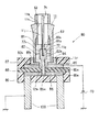
〔この発明による被膜形成用治具:図1,2〕
つぎに、この発明による被膜形成用治具の最良の実施形態を図1と図2によって説明する。図1はその被膜形成用治具の構造を使用状態で示す断面図であり、図2はそのガイドブッシュに装着される部材のみを示す断面図である。
なお、この図1と図2に示すガイドブッシュ11は、図1に示した超硬部材12を設けずに内周面11bを形成した例を示している。しかし、超硬部材を設けて内周面11bを形成したガイドブッシュにも全く同様に使用できる。
【0064】
この被膜形成用治具80は、ガイドブッシュ11に装着される部材と、真空槽内の底面上に固定設置される部材とからなる。
ガイドブッシュ11に装着される部材は、ロッド状の補助電極71と、補助電極支持部材72と、補助電極絶縁部材である第1の碍子81および第2の碍子82と、挿入部材83と、ガイドブッシュ受け84と、ダミー部材53とからなる。
【0065】
補助電極71は、補助電極支持部材72の太径部72aに嵌入して支持され、ガイドブッシュ11の内周面11bを形成する中心開口11j内に挿入される。この補助電極71は、ステンレスのような金属材料でロッド状に形成される。
補助電極絶縁部材である第1の碍子81および第2の碍子82は、ガイドブッシュ11の中心開口11jの軸線方向に分割されており、共に段差部11gに嵌入される。この第1の碍子81と第2の碍子82とは、いずれもセラミックスからなる絶縁材料で構成される。
【0066】
そして、この第1の碍子81と第2の碍子82とに、補助電極71と、この補助電極71を嵌入させて支持する補助電極支持部材72を挿入する貫通孔を設け、さらに第2の碍子82にはガイドブッシュ11から突き出すような突出部82aを設けている。補助電極71は補助電極支持部材72によって、ガイドブッシュ11の中心開口11j内の中央部に配置されるように支持される。
【0067】
第1の碍子81には、補助電極71を0.01mmから0.05mm程度の隙間寸法をもって通す小径の孔部81aと、補助電極支持部材72の太径部72aを位置決めする大径の孔部81bとを設ける。すなわち第1の碍子81には段付きの孔部を設けている。
【0068】
これに対して、第2の碍子82には、補助電極支持部材72の太径部72aと細径部72bとを位置決めする段付き孔部82bを設ける。
この2個の碍子81,82によって補助電極支持部材72の太径部72aを挟持し、第2の碍子82の突出部82aから補助電極支持部材72の細径部72bを突出させる。
【0069】
また、挿入部材83は、ガイドブッシュ11の中心開口11jの内周面11bを形成する部分と同じ内径を有する円筒状の導電材料からなり、その外形形状はガイドブッシュ11の中心開口11jの内周面11bの近傍の内面形状に合わせている。そして、この挿入部材83は、ガイドブッシュ11の中心開口11jの段差部11gにおける内周面11bの近傍に嵌入され、第1の碍子81によってその下端面が押さえられる。
【0070】
さらに、ガイドブッシュ11の段差部11g側の端部に設けられたネジ部11fの雄ネジに、雌ネジを設けたガイドブッシュ受け84を螺着する。このガイドブッシュ受け84は、ステンレスのような金属材料で構成され、その面積の大きい底面によって、ガイドブッシュ11と後述する第1の電極板85との接触面積を大きくすると共に、第1の碍子81と第2の碍子82がガイドブッシュ11の中心開口11j内から脱落するのを防止する役割をもつ。
【0071】
ダミー部材53は、ガイドブッシュ11の中心開口11jの内周面11bを形成する部分と略同じ内径を有する円筒状の導電材料からなり、該ガイドブッシュの前記内周面が開口する端面11h上に載置され、端面相互の離脱容易な接着等によって固定される。
なお、これらのうち挿入部材83とガイドブッシュ受け84、およびダミー部材53は必須のものではないが、これらを全てガイドブッシュ11に装着すると、図2に示すようになる。
【0072】
一方、真空槽内の底面上に固定設置される部材は、図1に示ように、ガイドブッシュ11と電気的に接続するための第1の電極板85と、真空槽の底面上に載置される脚部100と、補助電極支持部材72と電気的に接続するための第2の電極板86と、第1の電極板85と第2の電極板86とを絶縁して脚部100に固定する絶縁部材とからなる。第1の電極板85と第2の電極板86および脚部100は、いずれもステンレス鋼等の導電材料で構成される。
【0073】
絶縁部材は、第1の電極板85の露出部分を被覆する第1の絶縁部材87と、第2の電極板86の露出部分を被覆する第2の絶縁部材89と、第1の電極板85と第2の電極板86の間に介在する絶縁板である第3の絶縁部材88とからなる。これらはいずれも絶縁性材料であるアルミナやジルコニアなどのセラミックス、またはテフロン(登録商標)などのフッ素樹脂材料で構成するとよい。
【0074】
第1の絶縁部材87には、ガイドブッシュ受け84の外形寸法に合致する開口部87aを設けている。また、第1の電極板85には、第2の碍子82の突出部82aを嵌入させる孔部85aを形成し、第2の電極板86にはその突出部82aから突出する補助電極支持部材72の細径部72bを嵌入させる中心孔86aを設けている。
第3の絶縁部材88にも補助電極支持部材72の細径部72bを貫通させる孔部を設けている。この第3の絶縁部材88を載置する第2の絶縁部材89に凹部89aを設け、そこに第2の電極板86を嵌合させて面一に保持している。
【0075】
この被膜形成用治具80を使用する際には、図2に示すようにガイドブッシュ11の中心開口11j内に、挿入部材83と、補助電極および補助電極支持部材72を保持する第1の碍子81と第2の碍子82を挿入した後、ガイドブッシュ受け84をネジ部11fにねじ込んでこれらを固定保持し、このガイドブッシュ11の内周面11bが開口する端面11h上にダミー部材を載置固定する。
【0076】
そして、このガイドブッシュ11を持って、そのガイドブッシュ受け84を第1の絶縁部材87の開口部87aに嵌合させ、図1に示すようにそのガイドブッシュ受け84の底面を第1の電極板85の上面に接触させて、ガイドブッシュ11を軸線を垂直方向にして第1の電極板85上に載置する。
【0077】
このとき、ガイドブッシュ受け84を設けているため、ガイドブッシュ11と第1の電極板85との接触面積が大きくなる。そのため第1の電極板85に直流電源73を接続すれば、ガイドブッシュ11に直流負電圧を安定して印加することができる。なお、このガイドブッシュ受け84を、第1の電極板85側に固定して設けるようにしてもよい。
【0078】
この時また、第2の碍子82の突出部82aが第1の電極板85の孔部85aに嵌入する。そして、補助電極支持部材72の細径部72bは、第2の碍子82から下方に突出して、第3の絶縁部材88を貫通し、第2の電極板86の中心孔86aに嵌入する。
したがって、補助電極71は、補助電極支持部材72,第2の電極板86,脚部100,及び図示しない真空槽を介して接地されることになる。
【0079】
そして、ガイドブッシュ11の段差部11gに、第1の碍子81と第2の碍子82を介して補助電極71を支持する補助電極支持部材72を保持することにより、ガイドブッシュ11の中心開口11jの中心に正確に補助電極71を配置することができる。
補助電極71がガイドブッシュ11の中心開口11jの中心からずれて配置されると、補助電極71とガイドブッシュ11の内周面11bとの間のプラズマ放電のバランスがくずれ、硬質カーボン膜の膜厚や膜質にばらつきが生じる。
【0080】
そこで、ガイドブッシュ11の段差部11gの内径寸法に合うように第1の碍子81と第2の碍子82の外形を設定し、さらにこの碍子81,82の孔部81a,81b,82bで補助電極71を位置規制することにより、ガイドブッシュ11の中心開口11jの中心に補助電極71を正確に配置することができる。そのため、内周面11bに形成される硬質カーボン膜の膜厚や膜質にばらつきが発生しない。
【0081】
さらに、第2の碍子82のガイドブッシュ11から突き出す突出部82aが、前述のように第1の電極板85の孔部85aに嵌合するので、この突出部82aによって、ガイドブッシュ11と補助電極71との絶縁分離を完全に行なうことができる。
補助電極71の先端位置は、ダミー部材53を使用する場合には、図示のようにダミー部材53の上端面より1mm〜2mm内側になるようにし、ダミー部材53を使用しない場合には、ガイドブッシュ11の上端面11hより1mm〜2mm内側になるようにする。
【0082】
また、この被膜形成用治具80において、ガイドブッシュ11に電圧を印加する第1の電極板85は、その露出する面が第1の絶縁部材87で覆われているため、硬質カーボン膜を厚く形成するために長時間の成膜処理を行なっても、第1の電極板85でアーク放電などの異常放電が発生することはない。
【0083】
なお、この実施形態では、ガイドブッシュ受け84を設け、その底面が第1の電極板85の上面と接触するようにして、ガイドブッシュ11を第1の電極板85上に載置することにより、その安定性を高めると共にガイドブッシュ11への通電面積を増加させることができるが、このガイドブッシュ受け84を省略して、ガイドブッシュ11を直接第1の電極板85上に載置することも可能である。
【0084】
つぎに、この被膜形成用治具80、あるいは後述する複数のガイドブッシュ用の被膜形成用治具80′を用いてガイドブッシュ11の内周面11bに硬質カーボン膜を形成する方法の各実施例について図3乃至図11を用いて説明する。
【0085】
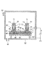
〔方法の第1実施例:図3〕
図3は、この発明によるガイドブッシュの内周面に硬質カーボン膜を形成する方法の第1実施例を説明するための装置の断面図である。
この第1実施例では、図3に示すようにガス導入口63と排気口65とを有する真空槽61内に、前述した被膜形成用治具80を用いてガイドブッシュ11を設置する。そのガイドブッシュ11と被膜形成用治具80の各部材との関係は図1に詳細に示したとおりであるから、その説明は省略する。
【0086】
真空槽61は接地されており、第1の電極板85は直流電源73の負極に接続される。この真空槽61は内部の上方にアノード79とフィラメント90を備えており、アノード79はアノード電源75に、フィラメント90はフィラメント電源77にそれぞれ接続されている。
そして、この真空槽61内を真空度が3×10⁻⁵torr以下になるように、図示しない排気手段によって排気口65から真空排気する。
【0087】
その後、ガス導入口63から炭素を含むガスとしてベンゼン(C6 H6 )を真空槽61内に導入して、真空槽61内の圧力を5×10⁻³torrになるように制御する。
ついで、ガイドブッシュ11に直流電源73から第1の電極板85を介してマイナス3kVの直流電圧を印加し、さらにアノード79にはアノード電源75からプラス50Vの直流電圧を印加し、さらにフィラメント90にはフィラメント電源77から30Aの電流が流れるように10Vの交流電圧を印加する。
【0088】
すると、真空槽61内のガイドブッシュ11の周囲領域にプラズマが発生して、プラズマCVDプロセスによって、ガイドブッシュ11の内周面を含む表面に、水素化アモルファス・カーボンによる硬質カーボン膜が形成される。
【0089】
この場合、ガイドブッシュ11の中心開口の中央に補助電極71が配置されているため、中心開口内の領域において同電位どうしが対向することがなくなるため、異常放電であるホロー放電の発生はなく、ガイドブッシュ11の内周面11bに形成される硬質カーボン膜の密着性が向上する。さらに、ガイドブッシュ11の中心開口内の長手方向で電位特性が均一になり、硬質カーボン膜の膜厚が、内周面11bの開口端面側から開口奥側まで均一な膜厚で形成される。
【0090】
この実施例および以下に説明する各実施例でもダミー部材53を使用しているが、その効果について説明する。
図示の硬質カーボン膜の被膜形成方法においては、ガイドブッシュ11の内面と外周部とにプラズマが発生する。そして、ダミー部材53を使用しない場合には、ガイドブッシュ11の端面に電荷が集中しやすく、ガイドブッシュ11の内面に比べて端面領域は電荷が高い状態、いわゆるエッジ効果が発生する。
【0091】
ここでは、ガイドブッシュ11の端面近傍のプラズマ強度は他の領域より大きく、しかも不安定でもある。さらにガイドブッシュ11の端部領域は、ガイドブッシュ11内面のプラズマと外周部のプラズマとの双方のプラズマの影響を受けることになる。
【0092】
そのような状態で硬質カーボン膜を形成すると、ガイドブッシュ11の開口端面から数mm奥側の領域と他の領域とでは、硬質カーボン膜の密着性および膜質が若干異なる。そこで、ガイドブッシュ11の開口端面にダミー部材53を配置して硬質カーボン膜を形成すれば、この膜質や密着性が異なる領域はガイドブッシュ11内面に形成されず、ダミー部材53の開口内面に形成されることになる。その結果、ガイドブッシュ11の内面には膜質や密着性が異なる領域はまったく形成されなくなる。
【0093】
また、この実施例によれば、第1の電極板85の露出部分を第1の絶縁部材87で覆っている。そのため、膜形成時間を長くしても、第1の電極板85でアーク放電が発生するようなことがなく、長時間のプラズマ放電が可能となったことにより、ガイドブッシュ11の内周面11bに形成する硬質カーボン膜の厚膜化を達成でき、ガイドブッシュの寿命を大幅に伸ばし、長期使用に対する信頼性を向上させることができる。さらに、ガイドブッシュ11の内周面11bに形成する硬質カーボン膜の膜質と膜厚の再現性も向上する。
【0094】
さらに、この実施例においては、ガイドブッシュ11の内周面11bの近傍領域に、挿入部材83を配置している。この挿入部材83の内径は、ガイドブッシュの中心開口11jの内周面11bを形成する部分の内径と略同じである。そのため、ガイドブッシュ11の内周面11bの近傍に段差がなくなる。
【0095】
すなわち、ガイドブッシュ11の硬質カーボン膜を形成する内周面11bおよびその近傍と補助電極71との間の隙間寸法が均一になり、補助電極71の周囲領域に形成されるプラズマが均一になり、プラズマ放電も安定する。したがって、ガイドブッシュ内周面に形成する硬質カーボン膜の膜厚の均一性と膜質とを向上させることができる。
【0096】
〔方法の第2実施例:図4〕
図4は、この発明によるガイドブッシュの内周面に硬質カーボン膜を形成する方法の第2実施例を説明するための装置の断面図である。
この図4において、図3と対応する部分には同一の符号を付してあり、またガイドブッシュ11と被膜形成用治具80の各部材との関係は図1に示したとおりであるから、それらの説明は省略する。
【0097】
この第2実施例に使用する真空槽61は、図1に示したアノード79とフィラメント90は備えていない。
この真空槽61内に、前述の第1実施例の場合と同様に被膜形成用治具80を用いて、ガイドブッシュ11を設置する。
【0098】
そして、この真空槽61内を図示しない排気手段によって、真空度が3×
10-5torr以下になるように、排気口65から真空排気した後、ガス導入口63から炭素を含むガスとしてメタンガス(CH4 )を真空槽61内に導入して、真空度を0.1torrになるように調整する。
その後、ガイドブッシュ11と接続する第1の電極板85に、発振周波数が13.56MHzの高周波電源69からマッチング回路67を介して高周波電力を印加して、真空槽61内にプラズマを発生させる。
【0099】
この第2実施例においても、ガイドブッシュ11の中心開口内に補助電極71を配置しているので、ガイドブッシュ11の外周部だけでなく中心開口内にも均一なプラズマが発生し、その内周面11bに良質の硬質カーボン膜を均一に形成することができる。その他の作用・効果についても前述の第1実施例の場合と同様である。
【0100】
〔方法の第3実施例:図5〕
図5は、この発明によるガイドブッシュの内周面に硬質カーボン膜を形成する方法の第3実施例を説明するための装置の断面図である。
この図5において、図3と対応する部分には同一の符号を付してあり、またガイドブッシュ11と被膜形成用治具80の各部材との関係は図1に示したとおりであるから、それらの説明は省略する。
【0101】
この第3実施例において、図3に示した第1実施例の硬質カーボン膜の形成方法と相違する点は、真空槽61の内部にアノード79及びフィラメント90を設けないことと、真空槽61内を真空度が3×10⁻⁵torr以下になるように真空排気した後、ガス導入口63から炭素を含むガスとしてメタンガス(CH4)を真空槽61内に導入して、真空度を0.1torrになるように調整することと、ガイドブッシュ11に接続する第1の電極板85に直流電源74からマイナス600Vの直流電圧を印加して、真空槽61内にプラズマを発生させることである。
【0102】
この第3実施例においても、ガイドブッシュ11の内周面11bに良質の硬質カーボン膜を均一に形成することができる。その他の作用・効果についても、前述の各実施例の場合と同様である。
【0103】
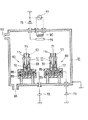
〔方法の第4実施例:図6〕
つぎに、図6から図8によって、複数の被膜形成治具80を用いて複数のガイドブッシュの内周面に同時に硬質カーボン膜を形成する方法の実施例を説明する。
【0104】
図6に示す第4実施例は、図3によって説明した第1実施例と同じプラズマ発生方法によるものである。そして、一つの真空槽61内に複数(図では2組)の被膜形成治具80,80を用いて複数のガイドブッシュ11,11を設置し、その各被膜形成用治具80,80の第1の電極板85,85に、それぞれ独立した直流電源73,73から、マイナス3kVの直流電圧を印加するようにしたこと以外は、図3の第1実施例の場合と同じである。
【0105】
このように、それぞれに独立した直流電源73,73から、各ガイドブッシュ11,11に直流負電圧を印加することにより、プラズマ放電の独立性を高めることができ、プラズマ放電間の干渉がなく、各ガイドブッシュ11の中心開口内におけるプラズマ放電が安定する。したがって、各ガイドブッシュ11の内周面11bに形成される硬質カーボン膜の膜厚のばらつきが少なく、膜質や密着性を向上させることができる。
【0106】
この実施例によれば、複数のガイドブッシュ11の各内周面11bに、同時に良質の硬質カーボン膜を均一に形成することができる。その他の作用・効果については前述の第1実施例の場合と同様である。
なお、一つの真空槽61内で、2個のガイドブッシュ11の内周面11bに同時に硬質カーボン膜を形成する例を示したが、3個以上のガイドブッシュ11の内周面11bに同時に硬質カーボン膜を形成することもできる。
【0107】
〔方法の第5実施例:図7〕
図7に示す第5実施例は、図4によって説明した第2実施例と同じプラズマ発生方法によるものである。そして、一つの真空槽61内に複数(図では2組)の被膜形成治具80,80を用いて複数のガイドブッシュ11,11を設置し、その各被膜形成用治具80,80の第1の電極板85,85に、それぞれ独立した高周波電源69,69から、それぞれマッチング回路67,67を介して周波数が13.56MHzの高周波電力を印加するようにしたこと以外は、図4の第2実施例の場合と同じである。
【0108】
この実施例においても、それぞれに独立した高周波電源69,69から各ガイドブッシュ11,11に高周波電力を印加することにより、プラズマ放電の独立性を高めることができ、プラズマ放電間の干渉がなく、各ガイドブッシュ11の中心開口内におけるプラズマ放電が安定し、前述の第4実施例と同等な効果がある。
【0109】
この実施例によっても、複数のガイドブッシュ11の各内周面11bに、同時に良質の硬質カーボン膜を均一に形成することができる。その他の作用・効果については前述の第2実施例の場合と同様である。
【0110】
〔方法の第6実施例:図8〕
図8に示す第6実施例は、図5によって説明した第3実施例と同じプラズマ発生方法によるものである。そして、一つの真空槽61内に複数(図では2組)の被膜形成治具80,80を用いて複数のガイドブッシュ11,11を設置し、その各被膜形成用治具80,80の第1の電極板85,85に、それぞれ独立した直流電源74,74からマイナス600Vの直流電圧を印加するようにしたこと以外は、図5の第3実施例の場合と同じである。
【0111】
この実施例においても、それぞれに独立した直流電源74,74から各ガイドブッシュ11,11に直流正電圧を印加することにより、プラズマ放電の独立性を高めることができ、プラズマ放電間の干渉がなく、各ガイドブッシュ11の中心開口内におけるプラズマ放電が安定し、前述の第4実施例と同等な効果がある。
【0112】
この実施例によっても、複数のガイドブッシュ11の各内周面11bに、同時に良質の硬質カーボン膜を均一に形成することができる。その他の作用・効果については前述の第3実施例の場合と同様である。
【0113】
〔複数のガイドブッシュ用の被膜形成用治具:図9,図10,図11)
図9乃至図11に示す複数のガイドブッシュの内周面に同時に硬質カーボン膜を形成する方法に使用する被膜形成用治具80′は、複数のガイドブッシュ11,11の内周面11bを形成する中心開口内にそれぞれ挿入されるロッド状の複数の補助電極71,71と、その各補助電極71,71をそれぞれ支持する複数の補助電極支持部材72,72と、各ガイドブッシュ71,71の中心開口内の段差部に嵌入され、各補助電極支持部材72,72を各ガイドブッシュ11,11に固定する複数組の碍子(補助電極絶縁部材)81,81,82,82とを備えている。
【0114】
また、複数のガイドブッシュ受け84,84と、複数のガイドブッシュ11,11に挿入される複数の挿入部材83,83と、各ガイドブッシュ11,11の開口端面上に載置される複数のダミー部材53,53も備えている。これらは、前述した被膜形成用治具80の各部材と同じである。
これらの、各部材は2個ずつに限らず、同時に設置し得るガイドブッシュ11の数に対応する数だけ備える。
【0115】
さらに、この被膜形成用治具80′は、複数のガイドブッシュ11,11をそれぞれ軸線を垂直方向にして電気的に導通させて載置する導電材料からなる共通の第1の電極板85′と、真空槽61内でその底面上に載置される導電材料からなる共通の脚部100と、その脚部100と一体的に設けられ各補助電極支持部材72,72の細径部を嵌入させる導電材料からなる共通の第2の電極板86′と、第1の電極板85′と第2の電極板86′とを絶縁して脚部100′に固定する共通の絶縁部材87′,88′,89′とを備えている。
第1の絶縁部材87′には、複数のガイドブッシュ受け84,84を嵌入させる複数の開口部を設けている。
【0116】
〔方法の第7実施例:図9〕
つぎに、上述した被膜形成用治具80′を用いて複数のガイドブッシュの内周面に同時に硬質カーボン膜を形成する方法の実施例を説明する。
図9は、この発明によるガイドブッシュの内周面に硬質カーボン膜を形成する方法の第7実施例を説明するための装置の断面図である。この図9において、図6と対応する部分には同一の符号を付し、それらの説明は省略する。
【0117】
この第7実施例は、複数のガイドブッシュ用の被膜形成用治具80′を用いて、真空槽61内に複数のガイドブッシュ11,11を設置し、共通の直流電源73から、共通の第1の電極板85′を通して各ガイドブッシュ11,11にマイナス3kVの直流電圧を印加するようにした以外は、図6に示した第4実施例と同じである。
【0118】
したがって、その作用・効果も第4実施例とほとんど同じであるが、被膜形成用治具の真空槽内61に固設する部材を複数のガイドブッシュ11に対して共通にし、各ガイドブッシュ11にマイナス3kVの直流電圧を印加する直流電源73も共通にしたので、より安価に効率よく、多数のガイドブッシュの内周面に同時に硬質カーボン膜を形成することができる。
【0119】
〔方法の第8実施例:図10〕
図10は、この発明によるガイドブッシュの内周面に硬質カーボン膜を形成する方法の第8実施例を説明するための装置の断面図である。この図10において、図7と対応する部分には同一の符号を付し、それらの説明は省略する。
【0120】
この第8実施例は、複数のガイドブッシュ用の被膜形成用治具80′を用いて、真空槽61内に複数のガイドブッシュ11,11を設置し、共通の高周波電源69から、共通のマッチング回路67と第1の電極板85′を通して各ガイドブッシュ11,11に高周波電力を印加するようにした以外は、図7に示した第5実施例と同じである。
【0121】
したがって、その作用・効果も第5実施例とほとんど同じであるが、被膜形成用治具の真空槽内61に固設する部材を複数のガイドブッシュ11に対して共通にし、各ガイドブッシュ11に高周波電力を印加する高周波電源69およびマッチング回路67も共通にしたので、より安価に効率よく、多数のガイドブッシュの内周面に同時に硬質カーボン膜を形成することができる。
【0122】
〔方法の第9実施例:図11〕
図11は、この発明によるガイドブッシュの内周面に硬質カーボン膜を形成する方法の第9実施例を説明するための装置の断面図である。この図11において、図8と対応する部分には同一の符号を付し、それらの説明は省略する。
【0123】
この第9実施例は、複数のガイドブッシュ用の被膜形成用治具80′を用いて、真空槽61内に複数のガイドブッシュ11,11を設置し、共通の直流電源74から、共通の第1の電極板85′を通して各ガイドブッシュ11,11にマイナス600Vの直流電圧を印加するようにした以外は、図8に示した第6実施例と同じである。
【0124】
したがって、その作用・効果も第6実施例とほとんど同じであるが、被膜形成用治具の真空槽内61に固設する部材を複数のガイドブッシュ11に対して共通にし、各ガイドブッシュ11にマイナス600Vの直流電圧を印加する直流電源74も共通にしたので、より安価に効率よく、多数のガイドブッシュの内周面に同時に硬質カーボン膜を形成することができる。
【0125】
〔補足説明〕
以上の図3乃至図11を用いて説明したこの発明による硬質カーボン膜の形成方法においては、炭素を含むガスとしてメタンガスやベンゼンガスを用いる実施例を説明したが、メタン以外にエチレンなどの炭素を含むガスや、あるいはヘキサンなどの炭素を含む液体の蒸発蒸気も使用することができる。
さらに、炭素を含むガスであるメタンガスやベンゼンガスやエチレンガスにアルゴン(Ar)ガス,窒素(N2)ガス,ヘリウム(He)ガス,水素(H2)ガス等を添加してもよい。
【0126】
このように、炭素を含むガスにアルゴンガスや窒素ガスを添加すると、膜形成速度を制御することができる。それらによって、硬質カーボン膜を緻密化することができ、さらに窒素やアルゴンによって硬質カーボン膜の表面をスパッタし、密着性や膜質が悪い硬質カーボン膜を除去することができ、膜質が向上する。さらに炭素を含むガスに水素を添加すると、炭素のダングリングボンドを水素で埋めることができ、硬質カーボン膜の膜質を向上させる効果がある。
【0127】
【発明の効果】
以上説明してきたように、この発明による被膜形成用治具を使用して、この発明による方法でガイドブッシュの内周面に硬質カーボン膜を形成すれば、膜質のよい硬質カーボン膜をガイドブッシュの内周面に密着性よく容易に形成することができ、それによってガイドブッシュの耐久性を飛躍的に高めることができる。
【図面の簡単な説明】
【図1】この発明による被膜形成治具の最良の実施形態の構造を使用状態で示す断面図である。
【図2】同じくそのガイドブッシュに装着される部材のみを示す断面図である。
【図3】この発明によるガイドブッシュの内周面に硬質カーボン膜を形成する方法の第1実施例を説明するための装置の断面図である。
【図4】同じく第2実施例を説明するための装置の断面図である。
【図5】同じく第3実施例を説明するための装置の断面図である。
【図6】同じく第4実施例を説明するための装置の断面図である。
【図7】同じく第5実施例を説明するための装置の断面図である。
【図8】同じく第6実施例を説明するための装置の断面図である。
【図9】この発明による被膜形成用治具の他の実施形態の構造とそれを使用したこの発明によるガイドブッシュの内周面に硬質カーボン膜を形成する方法の第7実施例を説明するための装置の断面図である。
【図10】同じく第8実施例を説明するための装置の断面図である。
【図11】同じく第9実施例を説明するための装置の断面図である。
【図12】この発明の方法によって内周面に硬質カーボン膜を形成したガイドブッシュの一例を示す縦断面図である。
【図13】同じくその斜視図である。
【図14】固定型のガイドブッシュ装置を設けた自動旋盤の主軸近傍のみを示す断面図である。
【図15】回転型のガイドブッシュ装置を設けた自動旋盤の主軸近傍のみを示す断面図である。
【符号の説明】
11:ガイドブッシュ 11a:外周テーパ面
11b:内周面 11c:摺り割り 11d:バネ部
11e:嵌合部 11f:ネジ部 11g:段差部
11h:端面 11j:中心開口
53:ダミー部材 61:真空槽
63:ガス導入口 65:排気口
67:マッチング回路 69:高周波電源
71:補助電極 72:補助電極支持部材
73,74:直流電源 75:アノード電源
77:フィラメント電源 79:アノード
80,80′:被膜形成用治具
81:第1の碍子 82:第2の碍子
83:挿入部材 84:ガイドブッシュ受け
85,85′:第1の電極板 86,86′:第2の電極板
87,87′:第1の絶縁部材
88,88′:第3の絶縁部材
89,89′:第2の絶縁部材
90:フィラメント 100,100′:脚部[0001]
BACKGROUND OF THE INVENTION
This invention is mounted on an automatic lathe and is rigid on an inner peripheral surface that is in sliding contact with a work piece of a guide bush that holds a round bar-like work piece so as to be rotatable and slidable in the axial direction near a cutting tool (blade). The present invention relates to a film forming jig used when forming a carbon film, and a method of forming a hard carbon film on the inner peripheral surface of a guide bush using the jig.
[0002]
[Prior art]
A guide bush provided on a column of an automatic lathe and holding a round bar-like workpiece rotatably near a cutting tool includes a rotary type and a fixed type. The rotary type always holds the work piece so that it can slide in the axial direction while rotating together with the work piece, and the fixed type allows the work piece to rotate and slide in the axial direction without rotating. Hold.
[0003]
Each type of guide bushing has an outer peripheral tapered surface, a slit for imparting elasticity to the guide bush, a screw portion for attaching to the column, and an inner peripheral surface for holding the workpiece. Since the surface is always in sliding contact with the work piece, it is easy to wear, especially in the case of a fixed type.
[0004]
For this reason, a cemented carbide or ceramic is fixedly provided on the inner peripheral surface of the guide bush that is in sliding contact with the workpiece by the rotation or sliding of the workpiece by brazing or the like, for example, Japanese Patent Laid-Open No. 4-141303. It has been proposed as seen in the publication. Thus, the provision of cemented carbide or ceramics excellent in wear resistance and heat resistance on the inner peripheral surface of the guide bush has an effect of suppressing the wear to some extent.
[0005]
However, even if cemented carbide or ceramics is provided on the inner peripheral surface in this way, for heavy cutting where the cutting amount is large and the machining speed is large with an automatic lathe, cemented carbide and ceramics also have a large friction coefficient and thermal conductivity. Since there is a problem that the workpiece is scratched or the gap between the guide bush and the workpiece is reduced in the diametrical direction, seizure occurs, increasing the cutting amount and the processing speed. I could not.
[0006]
The fixed guide bush can hold the work piece without blurring of its axis, so it can be machined with high roundness and high accuracy, it has less noise, and the structure of the automatic lathe is not complicated. There is an advantage that it can be made compact.
However, since the wear on the inner peripheral surface of the guide bush is much larger than in the case of the rotary type, there is a problem that it is difficult to further increase the cutting amount and the processing speed.
[0007]
In order to solve this problem, we form a hard carbon film on the inner peripheral surface that is in sliding contact with the workpiece in such a guide bush, thereby dramatically improving the wear resistance of the inner peripheral surface. It was proposed that the cutting amount and processing speed of an automatic lathe can be increased without causing scratches or seizures on the object.
[0008]
This hard carbon film is a hydrogenated amorphous carbon film and has a property very similar to diamond, and is also called diamond-like carbon (DLC).
This hard carbon film (DLC) has a high hardness (3000 Vv or more in Vickers hardness), excellent wear resistance, a small friction coefficient (1/8 of cemented carbide), and excellent corrosion resistance.
[0009]
As a method of forming this hard carbon film on the inner peripheral surface of the guide bush, for example, a film forming pressure of 5 × 10 5 in a gas atmosphere containing carbon in a vacuum chamber is used.-3
There is a plasma CVD method in which a torrr is applied to a guide bush by applying a minus 3 kV DC voltage from a DC power source to generate plasma to form a hard carbon film.
[0010]
[Problems to be solved by the invention]
However, in this plasma CVD method, plasma generated in the peripheral region of the guide bush mainly forms a hard carbon film by decomposing gas containing carbon. Although the carbon film can be formed with good uniformity, the hard carbon film formed on the inner surface of the central opening of the guide bush has problems of poor adhesion and poor film quality such as hardness.
[0011]
This is because the center opening of the guide bush is a space where electrodes of the same potential are opposed to each other, and the plasma in the center opening generates an abnormal discharge called a hollow discharge. The hard carbon film formed by this hollow discharge is a polymer-like film with poor adhesion, is easily peeled off from the inner peripheral surface of the guide bush, and has a low hardness.
[0012]
Further, in the above-described method for forming a hard carbon film, the film forming pressure is 5 × 10.-3At torr, a minus 3 kV DC voltage is applied to the
Thus, the pressure inside the vacuum chamber is 5 × 10⁻³In a high state like torr, the space in the vacuum chamber has a large amount of charges such as electrons, and the spatial impedance is low. Therefore, arc discharge, which is abnormal discharge, is likely to occur in the guide bush at the moment when plasma discharge starts.
[0013]
Furthermore, since the plasma discharge starts is also in the initial stage of film formation of the hard carbon film, it is an important time that affects the adhesion with the guide bush depending on the film quality formed in the initial stage of film formation.
Therefore, when arc discharge, which is abnormal discharge, occurs at the initial stage of plasma discharge, the film quality and adhesion of the hard carbon film deteriorates, causing a problem of peeling from the guide bush.
[0014]
This invention solves these problems, and makes it possible to easily form a hard carbon film with good film quality with good adhesion on the inner peripheral surface of the guide bush that is in sliding contact with the workpiece. Objective.
[0015]
[Means for Solving the Problems]
In order to achieve the above object, the present invention provides a film forming jig as described below, and a method for forming a hard carbon film on the inner peripheral surface of a guide bush using the film forming jig. suggest.
[0016]
A film forming jig according to the present invention is provided in a vacuum chamber when a hard carbon film is formed by plasma CVD on an inner peripheral surface that is in sliding contact with a workpiece of a guide bush mounted on an automatic lathe. It is a jig | tool for film formation for supporting and energizing it.
[0017]
The film forming jig includes a rod-shaped auxiliary electrode inserted into a central opening that forms the inner peripheral surface of the guide bush,
An auxiliary electrode support member made of a conductive material that supports the auxiliary electrode so as to face the inner peripheral surface along the axis of the central opening;
An auxiliary electrode insulating member that is fitted into a stepped portion having an inner diameter larger than the inner peripheral surface in the central opening of the guide bush, and that fixes the auxiliary electrode support member to the guide bush and protrudes in the direction opposite to the auxiliary electrode along the axis. When,
[0018]
A first electrode plate made of a conductive material for placing the guide bush by placing the end of the stepped portion side in the vertical direction with the axis line in a vertical direction;
Legs made of a conductive material placed on the bottom of the vacuum chamber;
A second electrode plate made of a conductive material provided integrally with the leg and connected to a portion of the auxiliary electrode support member protruding from the auxiliary electrode insulating member;
The first electrode plate and the second electrode plate are insulated and fixed to the leg portion.
[0019]
The film forming jig may be further provided with a guide bush receiver that is attached to an end portion of the guide bush on the stepped portion side or the first electrode plate and is made of a conductive material for expanding a contact area between the two.
Further, the guide bush is made of a cylindrical conductive material having the same inner diameter as the portion forming the inner peripheral surface of the central opening of the guide bush, and is formed between the inner peripheral surface of the step portion in the central opening and the auxiliary electrode insulating member. An insertion member to be inserted may be provided.
[0020]
The auxiliary electrode insulating member is made up of two insulators divided in the axial direction of the central opening of the guide bush, the auxiliary electrode support member is sandwiched by the two insulators, and the auxiliary electrode support member is separated from one of the insulators. The auxiliary electrode supported by the projection can be projected, and a part of the auxiliary electrode support member can be projected from the other insulator.
[0021]
An insulating member that insulates and fixes the first electrode plate and the second electrode plate to the leg; an insulating plate interposed between the first electrode plate and the second electrode plate; It is good to comprise by the insulating member which coat | covers each exposed part of an electrode plate and a 2nd electrode plate.
[0022]
Further, a dummy member made of a cylindrical conductive material having substantially the same inner diameter as a portion forming the inner peripheral surface of the central opening of the guide bush, and mounted on the end surface where the inner peripheral surface of the guide bush opens. It is good to provide.
[0023]
A plurality of auxiliary electrodes, auxiliary electrode supporting members, and auxiliary electrode insulating members are provided for mounting on a plurality of guide bushes, respectively, and insulated from the first electrode plate, the second electrode plate, and the legs. A member is a plurality of guide bushes.forA plurality of guide bushing film forming jigs may be provided in common.
[0024]
The method of forming the hard carbon film on the inner peripheral surface of the guide bush according to the present invention is performed as follows using the above-mentioned film forming jig.
An auxiliary electrode supporting member for supporting the auxiliary electrode of the film forming jig is fixed in the central opening of the guide bush by the auxiliary electrode insulating member, and the auxiliary electrode is opposed to the inner peripheral surface along the axis of the central opening. It arranges in.
[0025]
On the other hand, on the bottom surface in the vacuum chamber, the leg portion of the film forming jig, the second electrode plate fixed thereto, and the first electrode plate provided via the insulating member are placed.
Then, the guide bush is placed on the first electrode plate with the axis of the central opening in the vertical direction and placed on the first electrode plate, and is electrically connected to the first electrode plate. The electrode plate of the auxiliary electrode supporting member is connected to the power source, and the portion protruding from the auxiliary electrode insulating member of the auxiliary electrode supporting member is connected to the second electrode plate, and the auxiliary electrode is connected to the auxiliary electrode supporting member, the second electrode plate, the leg And ground through the vacuum chamber.
[0026]
Next, after evacuating the vacuum chamber, a gas containing carbon is introduced into the vacuum chamber, and power is supplied to the guide bush from the power source through the first electrode plate to generate plasma in the vacuum chamber. A hard carbon film made of hydrogenated amorphous carbon is formed on the inner peripheral surface of the guide bush.
[0027]
As the method for generating the plasma, a vacuum layer having an anode and a filament inside is used, and a DC voltage is applied to the guide bush from the power source through the first electrode plate, and the anode is applied to the anode. There is a method of applying a DC voltage and an AC voltage to the filament.
[0028]
Alternatively, plasma can be generated in the vacuum chamber by applying high-frequency power from the power source to the guide bush via the first electrode plate.
Furthermore, plasma can be generated in the vacuum chamber simply by applying a DC voltage to the guide bush from the power source via the first electrode plate.
[0029]
Thus, by using the film forming jig according to the present invention, the guide bush is securely supported in the vacuum chamber so that the axis of the central opening is vertical, and the auxiliary electrode is installed in the central opening along the axis. Because it can be placed and grounded easily, and the power supply to the guide bush can be performed easily and stably, a stable plasma is generated in the central opening of the guide bush, and high quality hard carbon is formed on the inner peripheral surface. A film can be formed with good adhesion.
[0030]
In addition, by providing a guide bush receiver for expanding the contact area between the guide bush and the first electrode plate between the guide bush and the first electrode plate, plasma discharge becomes more stable and the hard carbon film Variations in film thickness and film quality can be further suppressed.
[0031]
If the insertion member of the film forming jig is inserted into the stepped portion in the center opening of the guide bush so as to be adjacent to the inner peripheral surface, the inner side of the inner surface of the guide bush forming the hard carbon film is formed. By eliminating the step, the gap between the auxiliary electrode becomes uniform, the plasma formed in the surrounding area of the auxiliary electrode becomes uniform, and the hard carbon film can be formed more uniformly in both film quality and film thickness. it can.
[0032]
In addition, by arranging the dummy member on the end surface of the guide bush where the inner peripheral surface opens, the center opening and the center are aligned so that a uniform hard carbon film can be formed even at the opening of the inner peripheral surface. it can.
[0033]
Further, by covering the exposed portions of the first electrode plate and the second electrode plate with an insulating member, even if the film formation time is increased in order to increase the thickness of the hard carbon film, There is no risk of arc discharge or the like being an abnormal discharge at the exposed portion of the electrode plate.
[0034]
If a plurality of coating film forming jigs are used or a plurality of guide bushing film forming jigs are used, a hard carbon film is simultaneously formed on each inner peripheral surface of the plurality of guide bushes in one vacuum chamber. Can be formed.
[0035]
DETAILED DESCRIPTION OF THE INVENTION
Embodiments of the present invention will be described below with reference to the drawings.
[Description of automatic lathe using guide bush: Figs. 14 and 15]
First, the structure of an automatic lathe using a guide bush as an object of the present invention will be briefly described.
[0036]
FIG. 14 is a cross-sectional view showing only the vicinity of the spindle of a numerically controlled automatic lathe. This automatic lathe is provided with a fixed
The
[0037]
The
The
[0038]
Further, a
The tip position of the
[0039]
A chuck opening /
That is, when the chuck opening /
[0040]
The
For this reason, the leftward movement of the
[0041]
As a result, the diameter of the inner peripheral surface of the
When releasing the
Then, the
[0042]
For this reason, the pressing force between the outer peripheral
Further, a
[0043]
The
The
[0044]
By adjusting an
That is, when the
[0045]
A cutting tool (blade) 45 is provided further forward of the
[0046]
Next, an automatic lathe provided with a rotary guide bush device used in a state where the
As the rotary type guide bush device, there are a guide bush device in which the
[0047]
The rotary type
The rotary type
[0048]
The
[0049]
In the automatic lathe shown in FIG. 15, the configuration except that the
[0050]
[Description of guide bush: FIGS. 12 and 13]
Next, an example of the structure of the guide bush in which a hard carbon film is formed by the method of the present invention on the inner peripheral surface that is in sliding contact with the workpiece of the guide bush mounted on the automatic lathe described above will be described with reference to FIGS. To do.
[0051]
FIG. 12 is a longitudinal sectional view of the guide bush, and FIG. 13 is a perspective view showing an appearance. The
[0052]
And the
Further, the
[0053]
Then, by pressing the outer peripheral
Further, the
[0054]
As the material of the
Further, preferably on the inner
[0055]
For example, tungsten (W) is 85% to 90%, carbon (C) is 5% to 7%, and cobalt (Co) is 3% to 10% as a binder.Use things.
However, the
[0056]
Furthermore, when used in a fixed guide bushing device, the
Therefore, the hard carbon film (DLC) 15 described above is provided on the inner
[0057]
As described above, this hard carbon film has properties similar to diamond, has high mechanical strength, a low friction coefficient, lubricity, and excellent corrosivity.
Therefore, the
[0058]
Although this hard carbon film can be directly formed on the inner peripheral surface of the base material (SKS) of the
[0059]
This intermediate layer has a periodic tableofGroup IVb silicon (Si) or germanium (Ge), a compound of silicon or germanium, or a compound containing carbon such as silicon carbide (SiC) or titanium carbide (TiC) may be used. As the intermediate layer 16, titanium (Ti), tungsten (W), molybdenum (Mo), or a compound of tantalum (Ta) and silicon (Si) can also be applied.
Further, the intermediate layer 16 may be formed in a two-layer film of a lower layer made of titanium (Ti) or chromium (Cr) and an upper layer made of silicon (Si) or germanium (Ge).
[0060]
In this case, the lower layer titanium or chromium of the intermediate layer plays a role of maintaining the adhesion to the base material of the
The film thickness of these intermediate layers is about 0.5 μm. However, in the case of two layers, both the upper layer and the lower layer are about 0.5 μm.
[0061]
As the intermediate layer forming method, a sputtering method, an ion plating method, a chemical vapor deposition (CVD) method, or a thermal spraying method may be applied.
In the case where silicon carbide (SiC) is used as the
[0062]
The formation of the hard carbon film directly on the inner
[0063]
[Jig for forming a film according to the present invention: FIGS. 1 and 2]
Next, the best embodiment of the film forming jig according to the present invention will be described with reference to FIGS. FIG. 1 is a cross-sectional view showing the structure of the film forming jig in use, and FIG. 2 is a cross-sectional view showing only the members attached to the guide bush.
The
[0064]
The
The members attached to the
[0065]
The
The
[0066]
The
[0067]
The
[0068]
On the other hand, the
The large-
[0069]
The
[0070]
Further, a
[0071]
The
Of these, the
[0072]
On the other hand, the member fixedly installed on the bottom surface in the vacuum chamber is placed on the
[0073]
The insulating member includes a first insulating
[0074]
The first insulating
The third insulating
[0075]
When the
[0076]
Then, holding the
[0077]
At this time, since the
[0078]
At this time, the
Therefore, the
[0079]
Then, by holding the auxiliary
If the
[0080]
Therefore, the outer shape of the
[0081]
Furthermore, since the
When the
[0082]
Further, in this
[0083]
In this embodiment, the
[0084]
Next, each embodiment of the method of forming a hard carbon film on the inner
[0085]
[First Embodiment of Method: FIG. 3]
FIG. 3 is a cross-sectional view of an apparatus for explaining a first embodiment of a method for forming a hard carbon film on the inner peripheral surface of a guide bush according to the present invention.
In the first embodiment, as shown in FIG. 3, the
[0086]
The
The
[0087]
Thereafter, benzene (C6 H6) is introduced into the
Next, a minus 3 kV DC voltage is applied to the
[0088]
Then, plasma is generated in the peripheral region of the
[0089]
In this case, since the
[0090]
Although the
In the illustrated method for forming a hard carbon film, plasma is generated on the inner surface and the outer periphery of the
[0091]
Here, the plasma intensity in the vicinity of the end face of the
[0092]
When the hard carbon film is formed in such a state, the adhesion and film quality of the hard carbon film are slightly different between the area several mm behind the opening end face of the
[0093]
Further, according to this embodiment, the exposed portion of the
[0094]
Furthermore, in this embodiment, an
[0095]
That is, the gap between the inner
[0096]
[Second Embodiment of Method: FIG. 4]
FIG. 4 is a sectional view of an apparatus for explaining a second embodiment of the method for forming a hard carbon film on the inner peripheral surface of the guide bush according to the present invention.
In FIG. 4, the same reference numerals are given to the portions corresponding to FIG. 3, and the relationship between the
[0097]
The
The
[0098]
And the degree of vacuum is 3 × by the exhaust means (not shown) in the
10-FiveAfter evacuating from the
Thereafter, high-frequency power is applied to the
[0099]
Also in the second embodiment, since the
[0100]
[Third embodiment of the method: FIG. 5]
FIG. 5 is a sectional view of an apparatus for explaining a third embodiment of the method for forming a hard carbon film on the inner peripheral surface of the guide bush according to the present invention.
In FIG. 5, parts corresponding to those in FIG. 3 are denoted by the same reference numerals, and the relationship between the
[0101]
The third embodiment is different from the method of forming the hard carbon film of the first embodiment shown in FIG. 3 in that the
[0102]
Also in the third embodiment, a good quality hard carbon film can be uniformly formed on the inner
[0103]
[Fourth Embodiment of Method: FIG. 6]
Next, an embodiment of a method of simultaneously forming a hard carbon film on the inner peripheral surfaces of a plurality of guide bushes using a plurality of
[0104]
The fourth embodiment shown in FIG. 6 is based on the same plasma generation method as the first embodiment described with reference to FIG. Then, a plurality of
[0105]
Thus, by applying a DC negative voltage to the
[0106]
According to this embodiment, a good quality hard carbon film can be uniformly formed on each inner
Although an example in which a hard carbon film is simultaneously formed on the inner
[0107]
[Fifth embodiment of the method: FIG. 7]
The fifth embodiment shown in FIG. 7 is based on the same plasma generation method as the second embodiment described with reference to FIG. Then, a plurality of
[0108]
Also in this embodiment, by applying high frequency power to the
[0109]
Also according to this embodiment, a good quality hard carbon film can be uniformly formed on each inner
[0110]
[Sixth embodiment of the method: FIG. 8]
The sixth embodiment shown in FIG. 8 is based on the same plasma generation method as the third embodiment described with reference to FIG. Then, a plurality of
[0111]
Also in this embodiment, by applying a positive DC voltage to the
[0112]
Also according to this embodiment, a good quality hard carbon film can be uniformly formed on each inner
[0113]
[Film forming jig for a plurality of guide bushes: FIG.10 and 11)
The
[0114]
Also, a plurality of
These members are not limited to two, but are provided in a number corresponding to the number of
[0115]
Further, the film forming jig 80 'includes a common first electrode plate 85' made of a conductive material on which the plurality of
The first insulating
[0116]
[Seventh Embodiment of Method: FIG. 9]
Next, an embodiment of a method for simultaneously forming a hard carbon film on the inner peripheral surfaces of a plurality of guide bushes using the above-described film forming jig 80 'will be described.
FIG. 9 is a sectional view of an apparatus for explaining a seventh embodiment of the method for forming a hard carbon film on the inner peripheral surface of the guide bush according to the present invention. 9, parts corresponding to those in FIG. 6 are given the same reference numerals, and descriptions thereof are omitted.
[0117]
In the seventh embodiment, a plurality of
[0118]
Therefore, the operation and effect are almost the same as in the fourth embodiment, but a member fixed in the
[0119]
[Eighth Embodiment of Method: FIG. 10]
FIG. 10 is a cross-sectional view of an apparatus for explaining an eighth embodiment of the method for forming a hard carbon film on the inner peripheral surface of the guide bush according to the present invention. 10, parts corresponding to those in FIG. 7 are given the same reference numerals, and descriptions thereof are omitted.
[0120]
In the eighth embodiment, a plurality of
[0121]
Accordingly, the operation and effect are almost the same as in the fifth embodiment, but a member fixed in the
[0122]
[Ninth Embodiment of Method: FIG. 11]
FIG. 11 is a sectional view of an apparatus for explaining a ninth embodiment of the method for forming a hard carbon film on the inner peripheral surface of the guide bush according to the present invention. In FIG. 11, portions corresponding to those in FIG. 8 are denoted by the same reference numerals, and description thereof is omitted.
[0123]
In the ninth embodiment, a plurality of
[0124]
Accordingly, the operation and effect are almost the same as in the sixth embodiment, but a member fixed in the
[0125]
[Supplementary explanation]
In the method for forming a hard carbon film according to the present invention described with reference to FIGS. 3 to 11 above, the embodiment using methane gas or benzene gas as the gas containing carbon has been described. However, carbon such as ethylene is used in addition to methane. It is also possible to use gas containing liquid or liquid vapor containing carbon such as hexane.
Further, argon (Ar) gas, nitrogen (N2) gas, helium (He) gas, hydrogen (H2) gas, or the like may be added to methane gas, benzene gas, or ethylene gas, which is a gas containing carbon.
[0126]
Thus, when argon gas or nitrogen gas is added to the gas containing carbon, the film formation rate can be controlled. Accordingly, the hard carbon film can be densified, and the surface of the hard carbon film can be sputtered with nitrogen or argon to remove the hard carbon film having poor adhesion and film quality, thereby improving the film quality. Furthermore, when hydrogen is added to a gas containing carbon, dangling bonds of carbon can be filled with hydrogen, and the film quality of the hard carbon film is improved.
[0127]
【The invention's effect】
As described above, if the hard carbon film is formed on the inner peripheral surface of the guide bush by the method according to the present invention using the film forming jig according to the present invention, the hard carbon film having a good film quality is formed on the guide bush. It can be easily formed on the inner peripheral surface with good adhesion, whereby the durability of the guide bush can be dramatically increased.
[Brief description of the drawings]
FIG. 1 is a cross-sectional view showing the structure of the best embodiment of a film forming jig according to the present invention in use.
FIG. 2 is a cross-sectional view showing only members that are similarly mounted on the guide bush.
FIG. 3 is a cross-sectional view of an apparatus for explaining a first embodiment of a method for forming a hard carbon film on the inner peripheral surface of a guide bush according to the present invention.
FIG. 4 is a cross-sectional view of an apparatus for explaining a second embodiment.
FIG. 5 is a cross-sectional view of an apparatus for explaining a third embodiment.
FIG. 6 is a cross-sectional view of an apparatus for explaining a fourth embodiment.
FIG. 7 is a cross-sectional view of an apparatus for explaining a fifth embodiment.
FIG. 8 is a cross-sectional view of an apparatus for explaining a sixth embodiment.
FIG. 9 illustrates a seventh embodiment of the structure of another embodiment of the film forming jig according to the present invention and a method of forming a hard carbon film on the inner peripheral surface of the guide bush according to the present invention using the jig. It is sectional drawing of this apparatus.
FIG. 10 is a sectional view of an apparatus for explaining an eighth embodiment.
FIG. 11 is a cross-sectional view of an apparatus for explaining a ninth embodiment.
FIG. 12 is a longitudinal sectional view showing an example of a guide bush in which a hard carbon film is formed on the inner peripheral surface by the method of the present invention.
FIG. 13 is a perspective view of the same.
FIG. 14 is a cross-sectional view showing only the vicinity of the main shaft of an automatic lathe provided with a fixed guide bushing device.
FIG. 15 is a cross-sectional view showing only the vicinity of the main spindle of an automatic lathe provided with a rotary guide bushing device.
[Explanation of symbols]
11:
11b: Inner
11e:
11h:
53: Dummy member 61: Vacuum chamber
63:Gas inlet 65:exhaust port
67: Matching circuit 69: High frequency power supply
71: Auxiliary electrode 72: Auxiliary electrode support member
73, 74: DC power supply 75: Anode power supply
77: Filament power supply 79: Anode
80, 80 ': Film forming jig
81: First insulator 82: Second insulator
83: Insertion member 84: Guide bush receiving
85, 85 ':
87, 87 ′: first insulating member
88, 88 ′: third insulating member
89, 89 ′: second insulating member
90:
Claims (20)
前記ガイドブッシュの内周面を形成する中心開口内に挿入されるロッド状の補助電極と、
該補助電極を前記中心開口の軸線に沿って前記内周面と対向するように支持する導電材料からなる補助電極支持部材と、
前記ガイドブッシュの中心開口内の前記内周面より内径が大きい段差部に嵌入され、前記補助電極支持部材を該ガイドブッシュに固定すると共に前記軸線に沿って前記補助電極と反対方向に突出させる補助電極絶縁部材と、
前記ガイドブッシュを前記軸線を垂直方向にして前記段差部側の端部を電気的に導通させて載置する導電材料からなる第1の電極板と、
前記真空槽内でその底面上に載置される導電材料からなる脚部と、
該脚部と一体的に設けられ前記補助電極支持部材の前記補助電極絶縁部材から突出する部分と接続する導電材料からなる第2の電極板と、
前記第1の電極板と前記第2の電極板とを絶縁して前記脚部に固定する絶縁部材とからなることを特徴とする被膜形成用治具。A coating for supporting and energizing the guide bush in a vacuum chamber when a hard carbon film is formed on the inner peripheral surface of the guide bush mounted on the automatic lathe in sliding contact with the workpiece by plasma CVD. A forming jig,
A rod-shaped auxiliary electrode inserted into a central opening forming the inner peripheral surface of the guide bush;
An auxiliary electrode support member made of a conductive material that supports the auxiliary electrode so as to face the inner peripheral surface along the axis of the central opening;
The auxiliary bushing is fitted into a stepped portion having an inner diameter larger than the inner peripheral surface in the central opening of the guide bush, and the auxiliary electrode support member is fixed to the guide bush and protrudes in the direction opposite to the auxiliary electrode along the axis. An electrode insulating member;
A first electrode plate made of a conductive material for placing the guide bush by placing the end on the side of the stepped portion in a vertical direction with the axis line in a vertical direction;
Legs made of a conductive material placed on the bottom surface in the vacuum chamber;
A second electrode plate made of a conductive material provided integrally with the leg and connected to a portion protruding from the auxiliary electrode insulating member of the auxiliary electrode support member;
A film forming jig, comprising: an insulating member that insulates the first electrode plate and the second electrode plate and fixes the first electrode plate to the leg portion.
前記補助電極を支持する補助電極支持部材を前記補助電極絶縁部材によってガイドブッシュの中心開口内に固定して、前記補助電極を前記中心開口の軸線に沿って前記内周面と対向するように配設し、
ガス導入孔と排気孔を備えた真空槽内の底面上に、前記脚部および該脚部に固定された前記第1の電極板と前記第2の電極板と前記絶縁部材とを載置し、
前記ガイドブッシュを前記中心開口の軸線を垂直方向にして前記段差部側の端部を前記第1の電極板上に載置して該第1の電極板と電気的に導通させ、該第1の電極板を電源に接続すると共に、前記補助電極支持部材の前記補助電極絶縁部材から突出する部分を前記第2の電極板と接続して、前記補助電極を該補助電極支持部材,前記第2の電極板,前記脚部,および前記真空槽を介して接地し、
前記真空槽内を排気した後、前記ガス導入口から炭素を含むガスを該真空槽内に導入し、
前記ガイドブッシュに前記電源から前記第1の電極板を介して給電して、前記真空槽内にプラズマを発生させ、該ガイドブッシュの前記内周面に水素化アモルファス・カーボンによる硬質カーボン膜を形成することを特徴とするガイドブッシュの内周面に硬質カーボン膜を形成する方法。A method for forming a hard carbon film on the inner peripheral surface of a guide bush using the film forming jig according to claim 1,
An auxiliary electrode support member for supporting the auxiliary electrode is fixed in the central opening of the guide bush by the auxiliary electrode insulating member, and the auxiliary electrode is arranged so as to face the inner peripheral surface along the axis of the central opening. Set up
The leg portion, the first electrode plate fixed to the leg portion, the second electrode plate, and the insulating member are placed on a bottom surface in a vacuum chamber having a gas introduction hole and an exhaust hole. ,
The guide bush is placed on the first electrode plate with the axial line of the central opening in the vertical direction and placed on the first electrode plate, and is electrically connected to the first electrode plate. And connecting the electrode plate of the auxiliary electrode supporting member to the second electrode plate, and connecting the auxiliary electrode to the auxiliary electrode supporting member and the second electrode plate. Grounded through the electrode plate, the leg, and the vacuum chamber,
After exhausting the inside of the vacuum chamber, a gas containing carbon is introduced into the vacuum chamber from the gas inlet,
Power is supplied to the guide bush from the power source through the first electrode plate to generate plasma in the vacuum chamber, and a hard carbon film made of hydrogenated amorphous carbon is formed on the inner peripheral surface of the guide bush. A method of forming a hard carbon film on the inner peripheral surface of a guide bush.
前記ガイドブッシュの中心開口内の段差部に前記挿入部材を前記内周面に隣接させるように挿入し、
前記補助電極を支持する補助電極支持部材を前記補助電極絶縁部材によってガイドブッシュの中心開口内に固定して、前記補助電極を前記中心開口の軸線に沿って前記内周面と対向するように配設すると共に、該補助電極絶縁部材を前記挿入部材に当接させ、
ガス導入孔と排気孔を備えた真空槽内の底面上に、前記脚部および該脚部に固定された前記第1の電極板と前記第2の電極板と前記絶縁部材とを載置し、
前記ガイドブッシュを前記中心開口の軸線を垂直方向にして前記段差部側の端部を前記第1の電極板上に載置して該第1の電極板と電気的に導通させ、該第1の電極板を電源に接続すると共に、前記補助電極支持部材の前記補助電極絶縁部材から突出する部分を前記第2の電極板と接続して、前記補助電極を該補助電極支持部材,前記第2の電極板,前記脚部,および前記真空槽を介して接地し、
前記真空槽内を排気した後、前記ガス導入口から炭素を含むガスを該真空槽内に導入し、
前記ガイドブッシュおよび前記挿入部材に前記電源から前記第1の電極板を介して給電して、前記真空槽内にプラズマを発生させ、該ガイドブッシュの前記内周面に水素化アモルファス・カーボンによる硬質カーボン膜を形成することを特徴とするガイドブッシュの内周面に硬質カーボン膜を形成する方法。A method of forming a hard carbon film on the inner peripheral surface of a guide bush using the film forming jig according to claim 3,
Inserting the insertion member into the stepped portion in the central opening of the guide bush so as to be adjacent to the inner peripheral surface;
An auxiliary electrode support member for supporting the auxiliary electrode is fixed in the central opening of the guide bush by the auxiliary electrode insulating member, and the auxiliary electrode is arranged so as to face the inner peripheral surface along the axis of the central opening. And making the auxiliary electrode insulating member contact the insertion member,
The leg portion, the first electrode plate fixed to the leg portion, the second electrode plate, and the insulating member are placed on a bottom surface in a vacuum chamber having a gas introduction hole and an exhaust hole. ,
The guide bush is placed on the first electrode plate with the axial line of the central opening in the vertical direction and placed on the first electrode plate, and is electrically connected to the first electrode plate. And connecting the electrode plate of the auxiliary electrode supporting member to the second electrode plate, and connecting the auxiliary electrode to the auxiliary electrode supporting member and the second electrode plate. Grounded through the electrode plate, the leg, and the vacuum chamber,
After exhausting the inside of the vacuum chamber, a gas containing carbon is introduced into the vacuum chamber from the gas inlet,
Power is supplied to the guide bush and the insertion member from the power source through the first electrode plate, plasma is generated in the vacuum chamber, and the inner peripheral surface of the guide bush is hardened by hydrogenated amorphous carbon. A method for forming a hard carbon film on an inner peripheral surface of a guide bush, wherein the carbon film is formed.
前記ダミー部材を前記ガイドブッシュの前記内周面が開口する端面上に前記中
心開口と中心を一致させて配置し、
前記補助電極を支持する補助電極支持部材を前記補助電極絶縁部材によってガイドブッシュの中心開口内に固定して、前記補助電極を前記中心開口の軸線に沿って前記内周面および前記ダミー部材の内周面と対向するように配設し、
ガス導入孔と排気孔を備えた真空槽内の底面上に、前記脚部および該脚部に固定された前記第1の電極板と前記第2の電極板と前記絶縁部材とを載置し、
前記ガイドブッシュを前記中心開口の軸線を垂直方向にして前記段差部側の端部を前記第1の電極板上に載置して該第1の電極板と電気的に導通させ、該第1の電極板を電源に接続すると共に、前記補助電極支持部材の前記補助電極絶縁部材から突出する部分を前記第2の電極板と接続して、前記補助電極を該補助電極支持部材,前記第2の電極板,前記脚部,および前記真空槽を介して接地し、
前記真空槽内を排気した後、前記ガス導入口から炭素を含むガスを該真空槽内に導入し、
前記ガイドブッシュおよび前記ダミー部材に前記電源から前記第1の電極板を介して給電して、前記真空槽内にプラズマを発生させ、該ガイドブッシュの前記内周面に水素化アモルファス・カーボンによる硬質カーボン膜を形成することを特徴とするガイドブッシュの内周面に硬質カーボン膜を形成する方法。A method of forming a hard carbon film on the inner peripheral surface of a guide bush using the film forming jig according to claim 6,
The dummy member is arranged on the end surface where the inner peripheral surface of the guide bush is opened, with the center opening and the center aligned,
An auxiliary electrode supporting member for supporting the auxiliary electrode is fixed in the central opening of the guide bush by the auxiliary electrode insulating member, and the auxiliary electrode is arranged along the axis of the central opening with respect to the inner peripheral surface and the dummy member. Arranged to face the circumferential surface,
The leg portion, the first electrode plate fixed to the leg portion, the second electrode plate, and the insulating member are placed on a bottom surface in a vacuum chamber having a gas introduction hole and an exhaust hole. ,
The guide bush is placed on the first electrode plate with the axial line of the central opening in the vertical direction and placed on the first electrode plate, and is electrically connected to the first electrode plate. And connecting the electrode plate of the auxiliary electrode supporting member to the second electrode plate, and connecting the auxiliary electrode to the auxiliary electrode supporting member and the second electrode plate. Grounded through the electrode plate, the leg, and the vacuum chamber,
After exhausting the inside of the vacuum chamber, a gas containing carbon is introduced into the vacuum chamber from the gas inlet,
Power is supplied to the guide bush and the dummy member from the power source through the first electrode plate, plasma is generated in the vacuum chamber, and the inner peripheral surface of the guide bush is hardened by hydrogenated amorphous carbon. A method for forming a hard carbon film on an inner peripheral surface of a guide bush, wherein the carbon film is formed.
前記補助電極を支持する補助電極支持部材を前記補助電極絶縁部材によって複数のガイドブッシュの中心開口内にそれぞれ固定して、前記補助電極を該ガイドブッシュの中心開口の軸線に沿って前記内周面と対向するように配設し、
ガス導入孔と排気孔を備えた一つの真空槽内の底面上に、複数の前記被膜形成用治具の前記脚部および該脚部に固定された前記第1の電極板と前記第2の電極板と前記絶縁部材とをそれぞれ載置し、
前記複数の各ガイドブッシュをそれぞれ前記中心開口の軸線を垂直方向にして前記段差部側の端部を前記第1の電極板上に載置して該第1の電極板と電気的に導通させ、該第1の電極板をそれぞれ電源に接続すると共に、前記補助電極支持
部材の前記補助電極絶縁部材から突出する部分を前記第2の電極板と接続して、前記各補助電極を該補助電極支持部材,前記第2の電極板,前記脚部,および前記真空槽を介して接地し、
前記真空槽内を排気した後、前記ガス導入口から炭素を含むガスを該真空槽内に導入し、
前記複数のガイドブッシュに前記電源からそれぞれ前記第1の電極板を介して給電して、前記真空槽内にプラズマを発生させ、該各ガイドブッシュの前記内周面にそれぞれ水素化アモルファス・カーボンによる硬質カーボン膜を形成することを特徴とするガイドブッシュの内周面に硬質カーボン膜を形成する方法。A method of forming a hard carbon film on each of the inner peripheral surfaces of a plurality of guide bushes using a plurality of sets of the film forming jigs according to claim 1 or 2,
Auxiliary electrode supporting members for supporting the auxiliary electrodes are respectively fixed in the central openings of the plurality of guide bushes by the auxiliary electrode insulating members, and the auxiliary electrodes are arranged along the axis of the central openings of the guide bushes. Arranged to face the
On the bottom surface in one vacuum chamber provided with a gas introduction hole and an exhaust hole, the leg portions of the plurality of film forming jigs, the first electrode plate fixed to the leg portions, and the second electrode Placing the electrode plate and the insulating member,
Each of the plurality of guide bushes is placed on the first electrode plate with the axis of the central opening in the vertical direction, and is electrically connected to the first electrode plate. The first electrode plate is connected to a power source, and a portion of the auxiliary electrode support member protruding from the auxiliary electrode insulating member is connected to the second electrode plate, and each auxiliary electrode is connected to the auxiliary electrode. Grounded via a support member, the second electrode plate, the leg, and the vacuum chamber;
After exhausting the inside of the vacuum chamber, a gas containing carbon is introduced into the vacuum chamber from the gas inlet,
Power is supplied to each of the plurality of guide bushes from the power source through the first electrode plate to generate plasma in the vacuum chamber, and the inner peripheral surface of each guide bush is made of hydrogenated amorphous carbon. A method of forming a hard carbon film on the inner peripheral surface of a guide bush, characterized by forming a hard carbon film.
複数のガイドブッシュの前記内周面を形成する中心開口内にそれぞれ挿入されるロッド状の複数の補助電極と、
その各補助電極をそれぞれ前記複数のガイドブッシュの各中心開口の軸線に沿って前記内周面と対向するように支持する導電材料からなる複数の補助電極支持部材と、
前記各ガイドブッシュの中心開口内の前記内周面より内径が大きい段差部に嵌入され、前記各補助電極支持部材を該各ガイドブッシュに固定すると共に前記軸線に沿って前記各補助電極と反対方向に突出させる複数の補助電極絶縁部材と、
前記複数のガイドブッシュをそれぞれ前記軸線を垂直方向にして前記段差部側の端部を電気的に導通させて載置する導電材料からなる共通の第1の電極板と、
前記真空槽内でその底面上に載置される導電材料からなる共通の脚部と、
該脚部と一体的に設けられ前記各補助電極支持部材の前記各補助電極絶縁部材から突出する部分と接続する導電材料からなる共通の第2の電極板と、
前記第1の電極板と前記第2の電極板とを絶縁して前記脚部に固定する絶縁部材とからなることを特徴とする被膜形成用治具。A coating for supporting and energizing the guide bush in a vacuum chamber when a hard carbon film is formed on the inner peripheral surface of the guide bush mounted on the automatic lathe in sliding contact with the workpiece by plasma CVD. A forming jig,
A plurality of rod-shaped auxiliary electrodes each inserted into a central opening forming the inner peripheral surface of a plurality of guide bushes;
A plurality of auxiliary electrode support members made of a conductive material for supporting each auxiliary electrode so as to face the inner peripheral surface along the axis of each central opening of the plurality of guide bushes;
The guide bushing is fitted into a step portion having an inner diameter larger than the inner peripheral surface in the central opening of the guide bush, and the auxiliary electrode support member is fixed to the guide bush and is opposite to the auxiliary electrode along the axis. A plurality of auxiliary electrode insulating members projecting into
A common first electrode plate made of a conductive material for placing the plurality of guide bushes by placing the end portions on the stepped portion side in electrical conduction with the axis line being set in a vertical direction;
A common leg made of a conductive material placed on its bottom surface in the vacuum chamber;
A common second electrode plate made of a conductive material provided integrally with the legs and connected to a portion protruding from each auxiliary electrode insulating member of each auxiliary electrode supporting member;
A film forming jig, comprising: an insulating member that insulates the first electrode plate and the second electrode plate and fixes the first electrode plate to the leg portion.
前記複数の各補助電極を支持する補助電極支持部材を前記補助電極絶縁部材によって複数のガイドブッシュの各中心開口内に固定して、前記補助電極を前記各中心開口の軸線に沿って前記内周面と対向するように配設し、
ガス導入孔と排気孔を備えた一つの真空槽内の底面上に、前記共通の脚部および該脚部に固定された前記共通の第1の電極板と第2の電極板と絶縁部材とを載置し、
前記複数のガイドブッシュをそれぞれ前記中心開口の軸線を垂直方向にして前記段差部側の各端部を前記第1の電極板上に載置して該第1の電極板と電気的に導通させ、該第1の電極板を電源に接続すると共に、前記各補助電極支持部材の前記各補助電極絶縁部材から突出する部分をそれぞれ前記第2の電極板と接続して、前記各補助電極を該各補助電極支持部材,前記第2の電極板,前記脚部,および前記真空槽を介して接地し、
前記真空槽内を排気した後、前記ガス導入口から炭素を含むガスを該真空槽内に導入し、
前記複数のガイドブッシュに前記電源から前記第1の電極板を介してそれぞれ給電して、前記真空槽内にプラズマを発生させ、該各ガイドブッシュの前記内周面にそれぞれ水素化アモルファス・カーボンによる硬質カーボン膜を形成することを特徴とするガイドブッシュの内周面に硬質カーボン膜を形成する方法。A method of forming a hard carbon film on each of the inner peripheral surfaces of a plurality of guide bushes using the film forming jig according to claim 11 or 12,
An auxiliary electrode support member that supports each of the plurality of auxiliary electrodes is fixed in each central opening of the plurality of guide bushes by the auxiliary electrode insulating member, and the auxiliary electrode is moved along the axis of each central opening. Arranged to face the surface,
On the bottom surface in one vacuum chamber having a gas introduction hole and an exhaust hole, the common leg portion, the common first electrode plate, the second electrode plate, and the insulating member fixed to the leg portion, Placed,
Each of the plurality of guide bushes is placed on the first electrode plate with the axis of the central opening in the vertical direction, and is electrically connected to the first electrode plate. , Connecting the first electrode plate to a power source, connecting each auxiliary electrode supporting member protruding from the auxiliary electrode insulating member to the second electrode plate, and connecting the auxiliary electrodes to the power source. Grounded through each auxiliary electrode support member, the second electrode plate, the leg, and the vacuum chamber,
After exhausting the inside of the vacuum chamber, a gas containing carbon is introduced into the vacuum chamber from the gas inlet,
Power is supplied to the plurality of guide bushes from the power source through the first electrode plate to generate plasma in the vacuum chamber, and the inner peripheral surface of each guide bush is made of hydrogenated amorphous carbon. A method of forming a hard carbon film on the inner peripheral surface of a guide bush, characterized by forming a hard carbon film.
前記真空槽として、内部にアノードとフィラメントを備えたものを使用し、前記ガイドブッシュに前記電源から前記第1の電極板を介して直流電圧を印加するとともに、前記アノードに直流電圧を、前記フィラメントに交流電圧をそれぞれ印加して、前記真空槽内にプラズマを発生させることを特徴とするガイドブッシュの内周面に硬質カーボン膜を形成する方法。In the method for forming a hard carbon film on the inner peripheral surface of the guide bush according to any one of claims 7 to 10 and 17,
As the vacuum chamber, one having an anode and a filament inside is used, and a DC voltage is applied to the guide bush from the power source through the first electrode plate, and a DC voltage is applied to the anode. A method of forming a hard carbon film on the inner peripheral surface of the guide bush, wherein an AC voltage is applied to each of the two to generate plasma in the vacuum chamber.
前記ガイドブッシュに前記電源から前記第1の電極板を介して高周波電力を印加して、前記真空槽内にプラズマを発生させることを特徴とするガイドブッシュの内周面に硬質カーボン膜を形成する方法。In the method for forming a hard carbon film on the inner peripheral surface of the guide bush according to any one of claims 7 to 10 and 17,
A high carbon power is applied to the guide bush from the power source through the first electrode plate to generate plasma in the vacuum chamber, and a hard carbon film is formed on the inner peripheral surface of the guide bush Method.
前記ガイドブッシュに前記電源から前記第1の電極板を介して直流電圧を印加して、前記真空槽内にプラズマを発生させることを特徴とするガイドブッシュの内周面に硬質カーボン膜を形成する方法。In the method for forming a hard carbon film on the inner peripheral surface of the guide bush according to any one of claims 7 to 10 and 17,
A direct carbon voltage is applied to the guide bush from the power source through the first electrode plate to generate plasma in the vacuum chamber, and a hard carbon film is formed on the inner peripheral surface of the guide bush Method.
Priority Applications (1)
| Application Number | Priority Date | Filing Date | Title |
|---|---|---|---|
| JP22046797A JP3924051B2 (en) | 1996-08-15 | 1997-08-15 | Film forming jig and method for forming a hard carbon film on the inner peripheral surface of a guide bush using the same |
Applications Claiming Priority (7)
| Application Number | Priority Date | Filing Date | Title |
|---|---|---|---|
| JP21555696 | 1996-08-15 | ||
| JP21555996 | 1996-08-15 | ||
| JP8-215559 | 1996-08-19 | ||
| JP21735296 | 1996-08-19 | ||
| JP8-215556 | 1996-08-19 | ||
| JP8-217352 | 1997-02-07 | ||
| JP22046797A JP3924051B2 (en) | 1996-08-15 | 1997-08-15 | Film forming jig and method for forming a hard carbon film on the inner peripheral surface of a guide bush using the same |
Publications (2)
| Publication Number | Publication Date |
|---|---|
| JPH10121247A JPH10121247A (en) | 1998-05-12 |
| JP3924051B2 true JP3924051B2 (en) | 2007-06-06 |
Family
ID=27476740
Family Applications (1)
| Application Number | Title | Priority Date | Filing Date |
|---|---|---|---|
| JP22046797A Expired - Fee Related JP3924051B2 (en) | 1996-08-15 | 1997-08-15 | Film forming jig and method for forming a hard carbon film on the inner peripheral surface of a guide bush using the same |
Country Status (1)
| Country | Link |
|---|---|
| JP (1) | JP3924051B2 (en) |
Families Citing this family (1)
| Publication number | Priority date | Publication date | Assignee | Title |
|---|---|---|---|---|
| JP4957746B2 (en) * | 2009-04-13 | 2012-06-20 | 株式会社デンソー | Plasma generator |
-
1997
- 1997-08-15 JP JP22046797A patent/JP3924051B2/en not_active Expired - Fee Related
Also Published As
| Publication number | Publication date |
|---|---|
| JPH10121247A (en) | 1998-05-12 |
Similar Documents
| Publication | Publication Date | Title |
|---|---|---|
| US6056443A (en) | Guide bush and method of forming film over guide bush | |
| US5941647A (en) | Guide bush and method of forming hard carbon film over the inner surface of the guide bush | |
| US6419997B1 (en) | Guide bush and method of forming hard carbon film over the inner surface of the guide bush | |
| US5922418A (en) | Method of forming a DLC film over the inner surface of guide bush | |
| US5879763A (en) | Method of forming hard carbon film over inner surface of cylindrical member | |
| JP3224134B2 (en) | Peeling method for hard carbon film formed on inner peripheral surface of guide bush | |
| US5939152A (en) | Method of forming hard carbon film over the inner surface of guide bush | |
| JP3924051B2 (en) | Film forming jig and method for forming a hard carbon film on the inner peripheral surface of a guide bush using the same | |
| US6337000B1 (en) | Guide bush and method of forming diamond-like carbon film over the guide bush | |
| US6117496A (en) | Method of forming a hard carbon film over an inner surface of a guide bush using a jig | |
| JP3090430B2 (en) | Method of forming film on guide bush | |
| JP3043674B2 (en) | Method for forming hard carbon film on inner peripheral surface of guide bush | |
| JP3043670B2 (en) | Method of forming hard carbon film on inner peripheral surface of guide bush | |
| JPH0222471A (en) | Diamond coated sintered hard alloy and method for coating sintered hard alloy with diamond | |
| JP3043669B2 (en) | Guide bush and method for forming hard carbon film on inner peripheral surface thereof | |
| JP3665247B2 (en) | guide bush | |
| JPH10110270A (en) | Formation of hard carbon film on inner periphery of guide bushing | |
| JP2000071103A (en) | Guide bush, and forming method for diamond-like carbon film to guide bush | |
| JP3201773B2 (en) | Method for forming hard carbon film on inner peripheral surface of guide bush | |
| JPH11124671A (en) | Formation of coating onto inner circumferential face of guide bush | |
| JP2000024803A (en) | Guide bush and method for forming hard carbon film over guide bush | |
| JP2000042802A (en) | Guide bush and forming of coat on guide bush | |
| JPH11152568A (en) | Formation of hard carbon coating onto inner circumferential face of cylindrical member | |
| JPH1112743A (en) | Method for forming film on inner circumferential surface of guide bush | |
| JPH10328904A (en) | Coat forming method to inner peripheral surface of guide bush |
Legal Events
| Date | Code | Title | Description |
|---|---|---|---|
| A521 | Written amendment |
Free format text: JAPANESE INTERMEDIATE CODE: A523 Effective date: 20040811 |
|
| A621 | Written request for application examination |
Free format text: JAPANESE INTERMEDIATE CODE: A621 Effective date: 20040811 |
|
| A977 | Report on retrieval |
Free format text: JAPANESE INTERMEDIATE CODE: A971007 Effective date: 20070215 |
|
| TRDD | Decision of grant or rejection written | ||
| A01 | Written decision to grant a patent or to grant a registration (utility model) |
Free format text: JAPANESE INTERMEDIATE CODE: A01 Effective date: 20070220 |
|
| A61 | First payment of annual fees (during grant procedure) |
Free format text: JAPANESE INTERMEDIATE CODE: A61 Effective date: 20070223 |
|
| S533 | Written request for registration of change of name |
Free format text: JAPANESE INTERMEDIATE CODE: R313533 |
|
| R350 | Written notification of registration of transfer |
Free format text: JAPANESE INTERMEDIATE CODE: R350 |
|
| FPAY | Renewal fee payment (event date is renewal date of database) |
Free format text: PAYMENT UNTIL: 20120302 Year of fee payment: 5 |
|
| LAPS | Cancellation because of no payment of annual fees |