JP3919552B2 - 光ファイバ受容ハウジング - Google Patents
光ファイバ受容ハウジング Download PDFInfo
- Publication number
- JP3919552B2 JP3919552B2 JP2002027536A JP2002027536A JP3919552B2 JP 3919552 B2 JP3919552 B2 JP 3919552B2 JP 2002027536 A JP2002027536 A JP 2002027536A JP 2002027536 A JP2002027536 A JP 2002027536A JP 3919552 B2 JP3919552 B2 JP 3919552B2
- Authority
- JP
- Japan
- Prior art keywords
- housing
- optical fiber
- holding member
- optical
- receptacle
- Prior art date
- Legal status (The legal status is an assumption and is not a legal conclusion. Google has not performed a legal analysis and makes no representation as to the accuracy of the status listed.)
- Expired - Fee Related
Links
- 239000000835 fiber Substances 0.000 title description 3
- 239000013307 optical fiber Substances 0.000 claims description 58
- 238000003780 insertion Methods 0.000 claims description 14
- 230000037431 insertion Effects 0.000 claims description 14
- 239000000463 material Substances 0.000 claims description 3
- 230000003287 optical effect Effects 0.000 description 16
- 239000002184 metal Substances 0.000 description 6
- 238000000034 method Methods 0.000 description 5
- 230000005540 biological transmission Effects 0.000 description 4
- 238000006073 displacement reaction Methods 0.000 description 3
- 238000004891 communication Methods 0.000 description 2
- 230000008878 coupling Effects 0.000 description 2
- 238000010168 coupling process Methods 0.000 description 2
- 238000005859 coupling reaction Methods 0.000 description 2
- 241001391944 Commicarpus scandens Species 0.000 description 1
- 238000007796 conventional method Methods 0.000 description 1
- 238000005260 corrosion Methods 0.000 description 1
- 230000007797 corrosion Effects 0.000 description 1
- 238000001746 injection moulding Methods 0.000 description 1
- 238000009434 installation Methods 0.000 description 1
- 238000005304 joining Methods 0.000 description 1
- 238000004519 manufacturing process Methods 0.000 description 1
- 239000012778 molding material Substances 0.000 description 1
- 238000000465 moulding Methods 0.000 description 1
- 239000013308 plastic optical fiber Substances 0.000 description 1
- 238000003825 pressing Methods 0.000 description 1
- 230000008054 signal transmission Effects 0.000 description 1
- 239000000243 solution Substances 0.000 description 1
- 230000001360 synchronised effect Effects 0.000 description 1
- 238000003466 welding Methods 0.000 description 1
Images


Classifications
-
- G—PHYSICS
- G02—OPTICS
- G02B—OPTICAL ELEMENTS, SYSTEMS OR APPARATUS
- G02B6/00—Light guides; Structural details of arrangements comprising light guides and other optical elements, e.g. couplings
- G02B6/24—Coupling light guides
- G02B6/36—Mechanical coupling means
- G02B6/38—Mechanical coupling means having fibre to fibre mating means
- G02B6/3807—Dismountable connectors, i.e. comprising plugs
- G02B6/3833—Details of mounting fibres in ferrules; Assembly methods; Manufacture
- G02B6/3855—Details of mounting fibres in ferrules; Assembly methods; Manufacture characterised by the method of anchoring or fixing the fibre within the ferrule
-
- G—PHYSICS
- G02—OPTICS
- G02B—OPTICAL ELEMENTS, SYSTEMS OR APPARATUS
- G02B6/00—Light guides; Structural details of arrangements comprising light guides and other optical elements, e.g. couplings
- G02B6/24—Coupling light guides
- G02B6/36—Mechanical coupling means
- G02B6/38—Mechanical coupling means having fibre to fibre mating means
- G02B6/3807—Dismountable connectors, i.e. comprising plugs
- G02B6/3887—Anchoring optical cables to connector housings, e.g. strain relief features
- G02B6/3888—Protection from over-extension or over-compression
-
- G—PHYSICS
- G02—OPTICS
- G02B—OPTICAL ELEMENTS, SYSTEMS OR APPARATUS
- G02B6/00—Light guides; Structural details of arrangements comprising light guides and other optical elements, e.g. couplings
- G02B6/24—Coupling light guides
- G02B6/42—Coupling light guides with opto-electronic elements
- G02B6/4201—Packages, e.g. shape, construction, internal or external details
- G02B6/4202—Packages, e.g. shape, construction, internal or external details for coupling an active element with fibres without intermediate optical elements, e.g. fibres with plane ends, fibres with shaped ends, bundles
-
- G—PHYSICS
- G02—OPTICS
- G02B—OPTICAL ELEMENTS, SYSTEMS OR APPARATUS
- G02B6/00—Light guides; Structural details of arrangements comprising light guides and other optical elements, e.g. couplings
- G02B6/24—Coupling light guides
- G02B6/42—Coupling light guides with opto-electronic elements
- G02B6/4201—Packages, e.g. shape, construction, internal or external details
- G02B6/4219—Mechanical fixtures for holding or positioning the elements relative to each other in the couplings; Alignment methods for the elements, e.g. measuring or observing methods especially used therefor
- G02B6/4236—Fixing or mounting methods of the aligned elements
- G02B6/424—Mounting of the optical light guide
-
- G—PHYSICS
- G02—OPTICS
- G02B—OPTICAL ELEMENTS, SYSTEMS OR APPARATUS
- G02B6/00—Light guides; Structural details of arrangements comprising light guides and other optical elements, e.g. couplings
- G02B6/24—Coupling light guides
- G02B6/42—Coupling light guides with opto-electronic elements
- G02B6/4201—Packages, e.g. shape, construction, internal or external details
- G02B6/4249—Packages, e.g. shape, construction, internal or external details comprising arrays of active devices and fibres
-
- G—PHYSICS
- G02—OPTICS
- G02B—OPTICAL ELEMENTS, SYSTEMS OR APPARATUS
- G02B6/00—Light guides; Structural details of arrangements comprising light guides and other optical elements, e.g. couplings
- G02B6/24—Coupling light guides
- G02B6/42—Coupling light guides with opto-electronic elements
- G02B6/4201—Packages, e.g. shape, construction, internal or external details
- G02B6/4256—Details of housings
- G02B6/426—Details of housings mounting, engaging or coupling of the package to a board, a frame or a panel
Landscapes
- Physics & Mathematics (AREA)
- General Physics & Mathematics (AREA)
- Optics & Photonics (AREA)
- Optical Couplings Of Light Guides (AREA)
- Mechanical Coupling Of Light Guides (AREA)
Description
【発明の属する技術分野】
本発明は、光ファイバコネクタに関し、より詳細には光ファイバを保持する保持部材を有するハウジングに関する。
【0002】
【従来の技術】
通信情報ネットワーク等の複雑なデータバス伝送システムでは、データ移動用にプラスチック光ファイバが使用されることが多くなりつつある。高い伝送速度を保証しトラブルのない信号伝送を可能にするこのようなシステムは、電磁干渉を受けにくいと共に、配線費用を低減しコスト及び重量を削減する。このような光バスの用途に自動車の通信システムがある。例えば、オーディオコンポーネント、CDチェンジャ、音声で制御するシステム、内蔵型自動車電話及び更に別の要素が、光ファイバリング等の光バスにより互いに接続される。光ファイバリングを使用することにより、同期又は非同期データ伝送が十分な高伝送速度で実行される。
【0003】
個々の電子部品への光ファイバ接続又は複数の光ファイバの相互接続は、ハウジングを有する特殊な光ファイバコネクタにより達成されるのが代表的である。ハウジング内では、光ファイバが別の光ファイバ又は光部品に接続される。
【0004】
特に自動車の電子装置の分野において、極端に不良な周囲条件のため、光ファイバの接続は、振動及び腐食のみならず熱的安定性に関する厳しい要求事項に適合する必要がある。光ファイバ結合は、安価で好適には自動化された方法で達成される必要がある。
【0005】
光ファイバをハウジング内に固定する従来の方法は、図4に示されるように金属製クリップを使用する。ハウジング130は、光ファイバ122用のリセプタクル102と金属クリップ120用のリセプタクル124とを有する。光ファイバ122は、ハウジング130のリセプタクル102内に配置され、金属クリップ120の挿入により軸方向の変位に抗して機械的に固定される。この技法は、異なる長さの光ファイバの実装及びラッチを可能にする。光ファイバ122は、金属クリップ120によりハウジング130内に固定されるので、別の光ファイバとの接続が確保される。しかし、この解決手段は、組立の際に付加金属部品すなわちクリップ120を常に位置決めする必要があるという欠点を有する。このため、組立作業のコストが付加されてしまう。
【0006】
光ファイバをハウジングに固定する可能な別の方法は、レーザ溶接又は他の接合技法である。しかし、これらの技法は設備及びその設置コストが無視できない。加えて、これらの技法により、光ファイバ及びハウジング間が永久接続されてしまうので、接続の補修が困難である。
【0007】
【発明が解決しようとする課題】
従って、本発明は、光ファイバを可能な限り容易かつ安価に固定できる、光ファイバを光要素に接続するための光ファイバコネクタハウジングを提供することを目的とする。
【0008】
【課題を解決するための手段】
この目的及び他の目的は、光ファイバを光部品に接続するための本発明による光コネクタハウジングにより達成される。このハウジングは、ハウジングと同じ材料から製造される保持部材を有する。その結果、保持部材及びハウジングは同時に形成できるので、製造コストを低減する。
【0009】
一実施形態によれば、保持部材はハウジングと一体的に形成される。仮組立状態の保持部材が脱落・紛失するのを防止する保持ウエブが設けられる。これら保持ウエブは、組立中に若干の力を加えて保持部材を変位又は保持部材と係合させて分離してもよい。
【0010】
光ファイバを受容するハウジングの表面には、歯が設けられてもよい。この構造は、光ファイバが意図しない軸方向の変位から特に効果的に保護されるという利点がある。また、この構造は、保持部材の組立に必要な挿入力を低減させる。
【0011】
別の実施形態によれば、保持部材は組立工具用のプランジャ用のリセプタクルを有する。このリセプタクルは組立工具の位置決めを容易にするように作用するので、組立が簡単になる。
【0012】
また、凹部及びガイド突起がハウジングに沿って設けられ、保持部材が光ファイバに対して法線方向に正確に変位するのを確保する。
【0013】
組立状態の保持部材の意図しない変位を防止するために、ガイド突起が、挿入された保持部材と摩擦係合するように面取りされてもよい。これにより、組立中の信頼性の高い停止という利点が提供され、光ファイバ上に作用する力を可能な限り低く保つことができる。
【0014】
【発明の実施の形態】
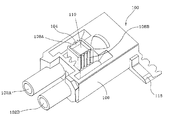
以下、添付図面を参照して本発明の実施形態を詳細に説明する。図1は、本発明の第1実施形態による、1本の光ファイバを1個の光要素に接続する光ファイバコネクタハウジングを示す斜視図である。図2は、図1のハウジングを逆側から見た斜視図である。図3は、本発明の第2実施形態による、2本の光ファイバを光要素に接続する光ファイバコネクタハウジングを示す斜視図である。
【0015】
本発明の実施形態は、以下に詳細に説明される。本発明による例示の同様な又は対応する要素には同一の参照番号が付される。
【0016】
図面は、プラスチック等の射出成形材料から製造できるハウジングの要素のみを示す。円形断面を有し好適にはプラスチックから製造される光ファイバは、図示されておらず、詳細に説明しない。明瞭にするために、ハウジングにより光ファイバが結合される光要素も同様に図面に示されていない。このような光要素は、例えば別の光ファイバ、ダイオード、或いは受動又は能動光部品であってもよい。
【0017】
第1実施形態である図1に示されるように、本発明のハウジング100は、光ファイバをそれぞれ受容する2個の略筒状リセプタクルすなわち挿入開口102A,102Bを具備する。ハウジングと同じ材料製の保持部材104が、仮組立状態で示される。
【0018】
保持部材及びハウジングと一体的に製造される破断容易な保持ウエブ106は、保持部材104が挿入開口102A,102B内に突出しないように、保持部材104を仮組立状態に固定する。この仮組立状態において、光ファイバは零挿入力で開口102A,102B内に挿入されてもよい。
【0019】
光ファイバがガイド105及び停止部107によりハウジング100の内部に一旦適切に位置決めされると、受容開口110に配置される組立工具のプランジャが使用されて、保持ウエブ106が破断して保持部材104が垂直に挿入領域102A,102B内に押圧されるように、矢印112方向に十分な挿入力が加えられる。次に、歯108A,108Bが光ファイバと係合する。
【0020】
図2は、図1の示されるハウジング100の逆側の斜視図である。ここで、光ファイバ用の筒状リセプタクル102A,102Bを見ることができる。リセプタクル102A,102Bは保持部材104の歯108A,108Bの領域に開口するので、保持部材104が挿入領域102A,102B内に押圧された後、光ファイバが強固に把持固定される。
【0021】
成形作業中に保持部材104及びハウジング100と共に製造される保持ウエブ106は、仮組立状態の保持部材104を信頼性高く保持することを保証し、できるだけ小さい力で保持部材104を挿入方向112に移動できるように寸法を設定されねばならない。ガイド突起115A,115Bは、保持部材104が光ファイバに対して直角の挿入方向に沿って変位することを保証する。組立工具の底面は停止部として利用することができ、保持部材104の挿入方向112に沿った押圧し過ぎを防止する。しかし、代わりに、保持部材104が挿入方向112に沿ってさらに変位されると、保持部材104をきつく把持固定するようにガイド突起115の側面116A,116Bを面取り(傾斜形成)してもよい。
【0022】
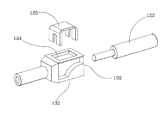
図3は、ダイオードを具備し、光部品に2本の光ファイバを接続する第2実施形態によるハウジング100を示す。光ファイバ用のリセプタクル102A,102Bは筒状の挿入補助部材として外方へ延びる。リセプタクル102A,102Bに対してハウジング100の反対側に配置されるのは、光部品(図示せず)を受容する保持装置118である。この実施形態において、保持部材104は、一体成形された破断し易い保持ウエブ106によりハウジング100上に最初は仮組立状態で保持される。歯108A,108Bは、光ファイバと係合する表面に同様に配置される。組立工具用の受容開口110は、2本の光ファイバを受容開口102A,102B内に固定するために、保持部材104を内方に押圧するプランジャの正確な位置決めを可能にする。
【0023】
光ファイバを光部品に接続するハウジング100を示す実施形態を示したが、本発明のハウジングは、複数の光ファイバ端部を相互接続する「ケーブル対ケーブル」結合用の部品としてもよい。
【図面の簡単な説明】
【図1】本発明の第1実施形態による、1本の光ファイバを1個の光要素に接続する光ファイバコネクタハウジングを示す斜視図である。
【図2】図1のハウジングを逆側から見た斜視図である。
【図3】本発明の第2実施形態による、2本の光ファイバを光要素に接続する光ファイバコネクタハウジングを示す斜視図である。
【図4】光ファイバ固定用の金属製クリップを有する従来の光ファイバコネクタハウジングの斜視図である。
【符号の説明】
100 ハウジング
102A,102B リセプタクル
104 保持部材
106 保持ウエブ
108A,108B 歯
110 リセプタクル(受容開口)
115 ガイド突起
Claims (1)
- 光ファイバを受容するためのハウジングであって、前記光ファイバ用のリセプタクルと、前記ハウジング内に相互ロックして受容され前記光ファイバの挿入方向に対して直交する方向に移動可能な保持部材とを具備し、前記保持部材は、前記ハウジングと同じ材料で製造されると共に、前記ハウジング上に最初は仮組立状態で支持され、前記ハウジングは、2本の光ファイバが互いに略平行に挿入可能である2個の前記リセプタクルを有するハウジングにおいて、
前記2本の光ファイバは、組立工具用の受容開口を有すると共に前記2本の光ファイバの間に介在する単一の前記保持部材により固定可能であることを特徴とする光ファイバ受容ハウジング。
Applications Claiming Priority (2)
| Application Number | Priority Date | Filing Date | Title |
|---|---|---|---|
| DE10105070.4 | 2001-02-05 | ||
| DE10105070 | 2001-02-05 |
Publications (2)
| Publication Number | Publication Date |
|---|---|
| JP2002258106A JP2002258106A (ja) | 2002-09-11 |
| JP3919552B2 true JP3919552B2 (ja) | 2007-05-30 |
Family
ID=7672854
Family Applications (1)
| Application Number | Title | Priority Date | Filing Date |
|---|---|---|---|
| JP2002027536A Expired - Fee Related JP3919552B2 (ja) | 2001-02-05 | 2002-02-05 | 光ファイバ受容ハウジング |
Country Status (4)
| Country | Link |
|---|---|
| US (1) | US6793404B2 (ja) |
| EP (1) | EP1229364B1 (ja) |
| JP (1) | JP3919552B2 (ja) |
| DE (1) | DE50105025D1 (ja) |
Families Citing this family (9)
| Publication number | Priority date | Publication date | Assignee | Title |
|---|---|---|---|---|
| GB2416927A (en) * | 2004-07-29 | 2006-02-08 | Itt Mfg Enterprises Inc | Cable Clamp |
| WO2009045562A1 (en) | 2007-04-13 | 2009-04-09 | Adc Telecommunications, Inc. | Optical fiber field termination kit |
| US7534050B2 (en) | 2007-04-13 | 2009-05-19 | Adc Telecommunications, Inc. | Field terminatable fiber optic connector assembly |
| US8083416B2 (en) * | 2007-11-30 | 2011-12-27 | Adc Telecommunications, Inc. | Hybrid fiber/copper connector system and method |
| DE102009028595B4 (de) * | 2009-08-17 | 2018-04-05 | Te Connectivity Germany Gmbh | Anschlussvorrichtung für einen Lichtwellenleiter |
| US8646813B1 (en) * | 2010-04-08 | 2014-02-11 | Sami Shemtov | Electrical conduit connector with two-point engagement |
| US8636425B2 (en) | 2011-03-15 | 2014-01-28 | Adc Telecommunications, Inc. | Fiber optic connector |
| CN104364686B (zh) | 2012-02-07 | 2016-11-16 | 泰科电子瑞侃有限公司 | 用于连接器的线缆端接组件和方法 |
| US9176285B2 (en) | 2012-05-03 | 2015-11-03 | Adc Telecommunications, Inc. | Fiber optic connector |
Family Cites Families (12)
| Publication number | Priority date | Publication date | Assignee | Title |
|---|---|---|---|---|
| US4211462A (en) * | 1979-01-22 | 1980-07-08 | Stewart Stamping Corporation, A Division Of Insilco Corp. | Electrical connector for termination cords with improved locking means |
| US4327964A (en) * | 1979-12-20 | 1982-05-04 | Texas Instruments Incorporated | Snap-action fiber optic connector |
| US4735477A (en) * | 1984-12-11 | 1988-04-05 | Amp Incorporated | Fiber optic splice terminal and method of using same |
| WO1987003969A1 (en) * | 1985-12-26 | 1987-07-02 | Amp Incorporated | Optical fiber connector |
| FR2593294B1 (fr) * | 1986-01-23 | 1990-01-05 | Alsthom Cgee | Connecteur pour fibres optiques |
| US4730892A (en) * | 1986-03-17 | 1988-03-15 | Northern Telecom Limited | Optical fiber mechanical splice |
| US4784456A (en) * | 1987-05-06 | 1988-11-15 | E. I. Du Pont De Nemours And Company | Fiber optic connector |
| US5013123A (en) * | 1988-04-18 | 1991-05-07 | Minnesota Mining And Manufacturing Company | Stamped precision lightguide interconnect centering element |
| US5133033A (en) * | 1990-05-31 | 1992-07-21 | Northern Telecom Limited | Optical fiber mechanical splice and method for its use |
| US5717813A (en) * | 1994-06-27 | 1998-02-10 | Fiberlign A Division Of Preformed Line Products (Canada) Ltd. | Fusion splice element for use in splicing optical fibers |
| JP3120361B2 (ja) * | 1995-10-26 | 2000-12-25 | モレックス インコーポレーテッド | 光ファイバーケーブル用コネクタ |
| FR2757959B1 (fr) * | 1996-12-30 | 1999-01-22 | Alsthom Cge Alcatel | Module d'epissure pour fibres optiques |
-
2001
- 2001-10-30 EP EP01125879A patent/EP1229364B1/de not_active Expired - Lifetime
- 2001-10-30 DE DE50105025T patent/DE50105025D1/de not_active Expired - Lifetime
-
2002
- 2002-02-04 US US10/067,688 patent/US6793404B2/en not_active Expired - Lifetime
- 2002-02-05 JP JP2002027536A patent/JP3919552B2/ja not_active Expired - Fee Related
Also Published As
| Publication number | Publication date |
|---|---|
| EP1229364B1 (de) | 2005-01-05 |
| EP1229364A2 (de) | 2002-08-07 |
| JP2002258106A (ja) | 2002-09-11 |
| DE50105025D1 (de) | 2005-02-10 |
| EP1229364A3 (de) | 2003-07-16 |
| US20020154868A1 (en) | 2002-10-24 |
| US6793404B2 (en) | 2004-09-21 |
Similar Documents
| Publication | Publication Date | Title |
|---|---|---|
| JP3801464B2 (ja) | ハイブリッドコネクタ | |
| JP3301791B2 (ja) | 光コネクタ | |
| KR100411838B1 (ko) | 유동 커넥터 조립체 | |
| JP3735011B2 (ja) | ハイブリッドコネクタの組み付け方法 | |
| JP3885988B2 (ja) | ハイブリッドコネクタ | |
| US9323007B1 (en) | One-piece optical fiber adapter capable of switching coupling polarity of optical fiber connectors | |
| JP3919552B2 (ja) | 光ファイバ受容ハウジング | |
| JPH07301726A (ja) | 光ファイバコネクタ | |
| JP2008505362A (ja) | ファイバ結合光学機器のパッケージ化 | |
| GB2325309A (en) | Optical backplane connector with floating housing | |
| US6227721B1 (en) | Optical connector | |
| JPS6285206A (ja) | 二本の光フアイバ−間の非永久的接続を行なう光フアイバ−接続装置、該装置に用いるプラグ部材および保持装置、および光フアイバ−の接続方法 | |
| US6048106A (en) | Optical module including an optical connector having retaining members | |
| US6435728B2 (en) | Optical connector housing, optical connector using the optical connector housing, and connection structure between an optical connector using the same optical connector housing and an optical component | |
| US5631989A (en) | Fiber and active optical device interconnection assembly | |
| JP2004045622A (ja) | 光アダプタ用取付金具及び光アダプタ | |
| KR20020059801A (ko) | 광코넥터 | |
| JPH10221559A (ja) | 光コネクタの結合構造 | |
| US6167184A (en) | Optical fiber fixing device for optically coupling optical fiber with optical communication module | |
| US6309111B1 (en) | System and method for limiting protrusion of a fiber-optic cable from a mounting structure | |
| JP2002258055A (ja) | プラグフレーム一体構造 | |
| US7206489B2 (en) | Fixing tool for fixing a fiber holding member to an optical fiber | |
| KR102749175B1 (ko) | 플러그 커넥터용 부착 시스템 | |
| CN223611750U (zh) | 适配器 | |
| JPS6333719A (ja) | 光波導体差込み結合部材のための中間部材 |
Legal Events
| Date | Code | Title | Description |
|---|---|---|---|
| A621 | Written request for application examination |
Free format text: JAPANESE INTERMEDIATE CODE: A621 Effective date: 20040324 |
|
| A977 | Report on retrieval |
Free format text: JAPANESE INTERMEDIATE CODE: A971007 Effective date: 20051006 |
|
| A131 | Notification of reasons for refusal |
Free format text: JAPANESE INTERMEDIATE CODE: A131 Effective date: 20051013 |
|
| A521 | Request for written amendment filed |
Free format text: JAPANESE INTERMEDIATE CODE: A523 Effective date: 20060112 |
|
| A131 | Notification of reasons for refusal |
Free format text: JAPANESE INTERMEDIATE CODE: A131 Effective date: 20060606 |
|
| A521 | Request for written amendment filed |
Free format text: JAPANESE INTERMEDIATE CODE: A523 Effective date: 20060906 |
|
| TRDD | Decision of grant or rejection written | ||
| A01 | Written decision to grant a patent or to grant a registration (utility model) |
Free format text: JAPANESE INTERMEDIATE CODE: A01 Effective date: 20070213 |
|
| A61 | First payment of annual fees (during grant procedure) |
Free format text: JAPANESE INTERMEDIATE CODE: A61 Effective date: 20070213 |
|
| R150 | Certificate of patent or registration of utility model |
Ref document number: 3919552 Country of ref document: JP Free format text: JAPANESE INTERMEDIATE CODE: R150 Free format text: JAPANESE INTERMEDIATE CODE: R150 |
|
| FPAY | Renewal fee payment (event date is renewal date of database) |
Free format text: PAYMENT UNTIL: 20100223 Year of fee payment: 3 |
|
| FPAY | Renewal fee payment (event date is renewal date of database) |
Free format text: PAYMENT UNTIL: 20110223 Year of fee payment: 4 |
|
| R250 | Receipt of annual fees |
Free format text: JAPANESE INTERMEDIATE CODE: R250 |
|
| FPAY | Renewal fee payment (event date is renewal date of database) |
Free format text: PAYMENT UNTIL: 20120223 Year of fee payment: 5 |
|
| R250 | Receipt of annual fees |
Free format text: JAPANESE INTERMEDIATE CODE: R250 |
|
| FPAY | Renewal fee payment (event date is renewal date of database) |
Free format text: PAYMENT UNTIL: 20130223 Year of fee payment: 6 |
|
| R250 | Receipt of annual fees |
Free format text: JAPANESE INTERMEDIATE CODE: R250 |
|
| FPAY | Renewal fee payment (event date is renewal date of database) |
Free format text: PAYMENT UNTIL: 20130223 Year of fee payment: 6 |
|
| FPAY | Renewal fee payment (event date is renewal date of database) |
Free format text: PAYMENT UNTIL: 20140223 Year of fee payment: 7 |
|
| R250 | Receipt of annual fees |
Free format text: JAPANESE INTERMEDIATE CODE: R250 |
|
| R250 | Receipt of annual fees |
Free format text: JAPANESE INTERMEDIATE CODE: R250 |
|
| R250 | Receipt of annual fees |
Free format text: JAPANESE INTERMEDIATE CODE: R250 |
|
| R250 | Receipt of annual fees |
Free format text: JAPANESE INTERMEDIATE CODE: R250 |
|
| R250 | Receipt of annual fees |
Free format text: JAPANESE INTERMEDIATE CODE: R250 |
|
| R250 | Receipt of annual fees |
Free format text: JAPANESE INTERMEDIATE CODE: R250 |
|
| LAPS | Cancellation because of no payment of annual fees |