JP3899498B2 - game machine - Google Patents
game machine Download PDFInfo
- Publication number
- JP3899498B2 JP3899498B2 JP20153498A JP20153498A JP3899498B2 JP 3899498 B2 JP3899498 B2 JP 3899498B2 JP 20153498 A JP20153498 A JP 20153498A JP 20153498 A JP20153498 A JP 20153498A JP 3899498 B2 JP3899498 B2 JP 3899498B2
- Authority
- JP
- Japan
- Prior art keywords
- player
- game
- hand
- display
- game machine
- Prior art date
- Legal status (The legal status is an assumption and is not a legal conclusion. Google has not performed a legal analysis and makes no representation as to the accuracy of the status listed.)
- Expired - Lifetime
Links
Images


Classifications
-
- G—PHYSICS
- G07—CHECKING-DEVICES
- G07F—COIN-FREED OR LIKE APPARATUS
- G07F17/00—Coin-freed apparatus for hiring articles; Coin-freed facilities or services
- G07F17/32—Coin-freed apparatus for hiring articles; Coin-freed facilities or services for games, toys, sports, or amusements
-
- G—PHYSICS
- G07—CHECKING-DEVICES
- G07F—COIN-FREED OR LIKE APPARATUS
- G07F17/00—Coin-freed apparatus for hiring articles; Coin-freed facilities or services
- G07F17/32—Coin-freed apparatus for hiring articles; Coin-freed facilities or services for games, toys, sports, or amusements
- G07F17/3202—Hardware aspects of a gaming system, e.g. components, construction, architecture thereof
- G07F17/3204—Player-machine interfaces
- G07F17/3209—Input means, e.g. buttons, touch screen
-
- A—HUMAN NECESSITIES
- A63—SPORTS; GAMES; AMUSEMENTS
- A63F—CARD, BOARD, OR ROULETTE GAMES; INDOOR GAMES USING SMALL MOVING PLAYING BODIES; VIDEO GAMES; GAMES NOT OTHERWISE PROVIDED FOR
- A63F2300/00—Features of games using an electronically generated display having two or more dimensions, e.g. on a television screen, showing representations related to the game
- A63F2300/10—Features of games using an electronically generated display having two or more dimensions, e.g. on a television screen, showing representations related to the game characterized by input arrangements for converting player-generated signals into game device control signals
- A63F2300/1012—Features of games using an electronically generated display having two or more dimensions, e.g. on a television screen, showing representations related to the game characterized by input arrangements for converting player-generated signals into game device control signals involving biosensors worn by the player, e.g. for measuring heart beat, limb activity
Description
【0001】
【発明の属する技術分野】
本発明はゲーム機に係わり、遊戯者が発する音声、及び/又は動作を取り込み、遊戯者の音声、及び/又は、遊戯者の動作から遊戯者の微妙な心理状態の揺れや遊戯者の操作指令をゲーム処理基板に取り込み、ゲームの展開の多様化を図ったゲーム機に関するものである。
【0002】
【従来の技術】
従来、この種の対面式ゲーム機は、例えば、ゲーム上の登場人物(ディーラ)と少なくとも一人の遊戯者が対面して行うゲームを模倣したものであり、あらかじめ記憶しておいたゲームプログラムを処理進行させることに伴って対面式ゲームが展開するようなに動作する。
【0003】
このような対面式ゲーム機の一例として、特許第2660586号公報に記載されたものがある。この公報に記載された対面式ゲーム機は、前記対面式ゲーム機の正面中央部に設けられた投影空間と、前記投影空間の裏に設けられた背景と、前記投影空間の手前に設けられ当該投影空間及びサテライト表示手段を見てゲームプレイを行う操作部を有するサテライト部と、前記投影空間に向いた表示面に表示映像を映す表示装置と、前記表示装置の表示画像の虚像を前記背景の手前に形成する一方、前記背景を透過させる虚像形成手段とを備えたことにより、前記表示画像と前記背景を組み合わせて実際にディーラと対面しているように見える合成画像をみながら、遊戯者が対面式ゲームを行うようにした装置である。
【0004】
このゲーム機によれば、遊戯者は、実際にディーラと対面しているように見える合成画像をみながらゲームを体験するため、ディーラからカードを実際に配って貰うという感じを味わいつつゲームの進行できる利点がある。このゲームにおいては、遊戯者は、ゲームの展開に伴って操作部を操作し、ディーラに対して各種の指示等を与えることができる。
【0005】
【発明が解決しようとする課題】
しかしながら、上述した従来のゲーム機にあっては、遊戯者は、実際にディーラと対面しているように見える合成画像をみながらゲームを体験することができるという利点はあるものの、ディーラに対しては操作部の操作、キーボード装置のキーの押下、マウスボタンの押下のみによって与える情報だけであるため、入力情報が固定化され、遊戯者の微妙な心理状態をゲーム機に伝えることが困難であった。そのために、ディーラの動作や表情が画一的となってしまうなど、ゲームの展開性が乏しく、変化のないゲームしか実行できないという問題があった。そして、このようなゲーム機は、対面しているような、すなわちゲーム機と遊戯者との双方向の係わり(インタラクディブ性)に富んだゲーム感覚にはほど遠いものであった。
【0006】
そこで、本発明者等は、遊戯者の心理状態を遊戯者の音声や動作から把握して、インタラクティブ感覚に優れたゲーム機を提供することを目的として本発明を完成するに至った。本発明の他の目的は、遊戯者の音声や動作などの各種の状態を認識することにより、かかるインタラクティブ性に優れたゲーム機を提供することである。本発明の他の目的は、遊戯者の内面の微妙な心理状態を、遊戯者の音声や動作を検出し分析することによってゲームの展開に反映させたゲーム機を提供することである。
【0007】
また、本発明の他の目的は、遊戯者の音声の状態に応じてゲーム展開を変化させるゲーム機を提供することである。本発明の更に他の目的は、遊戯者の動作の状態に応じてゲーム展開を変化させるゲーム機を提供することにある。
【0008】
【課題を解決するための手段】
この発明に係るゲーム機は、遊戯者からの入力情報に応じて所定のゲームプログラムを実行して行くゲーム機において、遊戯者から発生される音声及び/又は動作を認識する手段と、認識された音声や動作の状態を判定する手段と、音声や動作の前記状態に応じて前記ゲーム機を応答処理動作させる処理手段とを備える。
【0009】
本発明は、遊戯者から発せられる音声や動作等を介して、遊戯者の内面の微妙な心理状態をシミュレートし、これをゲームの展開に反映させることを特徴とする。また、遊戯者の動作、例えば、手先のカード裁きから、遊戯者の得手不得手等の熟練度をシミュレートし、これをゲームの展開に反映させることを特徴とする。本発明は、また、係る動作を検出することにより、キーボードやコントロールパッドのような周辺機器のボタン操作などではどうしても達成されないであろう、例えば、実際のカードゲームに近づけた入力をゲーム機に与え、この本物に近い入力に応じた処理をゲーム機に実行させることを特徴とするものである。
【0010】
本発明において、音声からは、音声のレベル、音調、抑揚、トーンなどの各種特徴が抽出される。遊戯者の動作からは、動きの早さ、動きの幅、動きの時間などの各種特徴が抽出される。動きとしては、手先の動きが主要な実施形態であるが、これに限らず、遊戯者の身体のある部分の動きであっても良い。この動きには、遊戯者の顔の表情も含まれる。
【0011】
好ましくは、遊戯者との対話型ゲーム処理手段を備える。
【0012】
好ましくは、遊戯者が発する音声を音声信号に変換する音声信号変換手段と、この音声信号を認識処理しその認識結果に応じた認識信号を出力する音声認識手段と、この認識信号の状況に応じたゲームの展開内容とする処理手段とを備える。
【0013】
好ましくは、前記処理手段は、認識指令に応じてゲームの映像及び/又はゲームの音声を展開させる。
【0014】
好ましくは、前記音声認識手段は、音声信号パターンの認識、及び/又は、音声信号レベルの認識をするものである。
【0015】
好ましくは、前記音声認識手段は、各種音声パターンを予め記憶しておき、入力された音声信号が前記各種音声パターンのいずれにより近似しているかを判定するものである。
【0016】
この発明に係るゲーム機は、前記遊戯者の動作を映像信号に変換する撮像手段と、この映像信号を画像認識して画像認識信号を出力する画像認識手段と、この画像認識信号の状況に応じてゲームを展開する処理手段を備える。
【0017】
好ましくは、前記撮像手段及び画像認識手段は時分割にて使用できるものである。
【0018】
好ましくは、前記撮像手段は、前記遊戯者の手先の動作を取得するものである。
【0019】
好ましくは、前記撮像手段は映像をレンズによって集光して映像信号に変化できるMOS型撮像素子を備え、前記画像認識手段は、当該MOS型撮像素子からの映像信号を画像認識する。
【0020】
この発明に係るゲーム機は、前記遊戯者の動作を検出して電気信号にする入力手段と、この入力手段からの電気信号を基に遊戯者の動作を演算する演算手段と、この演算手段からの演算結果に応じてゲームを展開する処理手段を備えた。
【0021】
好ましくは、前記入力手段は、所定の空間に赤外線を発射する発光部と、所定空間内のおける遊戯者の動きに応じた前記赤外線の反射光を受光して電気信号にする受光部とからなる。
【0022】
好ましくは、前記受光部は、暗箱と、この暗箱内に設けられ複数分割した赤外線素子を有する赤外線センサーユニットとからなる。
【0023】
好ましくは、所定の空間内の遊戯者の動きは、遊戯者の手の動きを取得するものである。
【0024】
好ましくは、前記入力手段は、少なくとも2つのセンサを含む第1検出部と、少なくとも1つのセンサを含む第2検出部とを備え、前記第1検出部は、前記第2検出部により形成される直線上になく、前記演算手段は、前記第1検出部の出力に基づき遊戯者の手の第1の動きを検出し、前記第2検出部の出力に基づき遊戯者の手の第2の動きを検出する。
【0025】
好ましくは、前記第1の動きは手を左右に動かす動作であり、前記第2の動きは手を所定の位置に置く動作である。
【0026】
好ましくは、前記入力手段の上には、手の動作を説明するパネルが設けられ、前記センサは前記パネルを介して遊戯者の手の動きを検出する。
【0027】
この発明に係るゲーム機は、前記遊戯者の動作を検出して電気信号にする光学入力手段と、この光学入力手段からの電気信号を基に遊戯者の動作の演算する演算手段と、遊戯者が直接操作する操作手段と、前記演算手段からの演算結果あるいは前記操作表示盤からの操作指令に応じてゲームを展開する処理手段を備えた。
【0028】
好ましくは、前記操作手段は、光学入力手段より遊戯者側に設けられている。
【0029】
好ましくは、前記操作手段は、遊戯者側にゆくに従って下側に向く傾きをもって配置されている。
【0030】
【発明の実施の形態】
以下、本発明に係る実施の形態について図面を参照して説明する。
【0031】
<第1の実施の形態>
図1ないし図3は本発明に係る第1の実施の形態を説明するためのものであり、図1は同装置の斜視図、図2は同装置の一部を断面にした平面図、図3は同装置を一部破断して示す側面図である。
【0032】
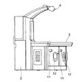
これらの図において、対面式ゲーム機1は、大別すると、ディーラを模したキャラクタが画面に表示される立設部2と、遊戯者側の複数のサテライト3,3,…と、前記立設部2の上部からサテライト3,3,…に張り出した張出部4とから構成されており、かつ前記サテライト3,3,…が配置された筐体部5等の内部にマザーボード6や電源回路その他の回路が設けられている。なお、マザーボード6は、上記ゲーム・その他の情報処理を行うことができる。
【0033】
前記立設部2には遊戯者に向けてCRTディスプレイ7が配置されており、このディスプレイ7には例えばディーラに模したキャラクタが表示されるようになっている。この立設部2の手前のテーブル8にはさらにCRTディスプレイ9が配置されており、このディスプレイ9には例えばディーラの分のカード等が表示される。このテーブル8において、このディスプレイ9の表示面は遊戯者によく見えるようにするために、図3に示すように、遊戯者側に傾けられている。これらディスプレイプレイ7,9は前記マザーボード6に電気的に接続されている。
【0034】
前記サテライト3,3,…には、それぞれCRTのサテライトディスプレイ10,10,…が配置されており、各サテライトディスプレイ10,10,…には各遊戯者のカードがそれぞれ表示されるようになっている。こられサテライトディスプレイ10,10,…はそれぞれマザーボード6に電気的に接続されている。なお、上記サテライトディスプレイ10はCRTで構成したが、もちろん他のディスプレイであってもよい。すなわち、サテライトディスプレイ10としては、プラズマディスプレイ、液晶ディスプレイ、その他表示形式が異るディスプレイであって、電気信号を画像に表示できる装置であればその種類を問わない。
【0035】
前記サテライト3,3,…には、メタル投入口11,11,…と、メタル受け皿12,12,…とがそれぞれ設けられており、メタル投入口11,11,…からメタルを賭けて、ゲームに勝った場合には勝った遊戯者のメタル受け皿12,12,…にメダルの配当を受けられるようになっている。
【0036】
さらに、前記各サテライト3,3,…にはマイクロフォン13,13,…がそれぞれ設けられており、これらマイクロフォン13,13,…は電気的にマザーボード6に接続されている。こられマイクロフォン13,13,…は、各サテライト3,3,…に座った遊戯者の発する音声を音声信号に変換してマザーボード6に供給できるようになっている。 前記張出部4の先端には撮像手段であるCCDカメラ14,14,…が配置されており、各サテライト3,3,…の各遊戯者の動き、特に手の動き等をCCDカメラ14,14,…により映像信号に変換してマザーボード6に与えるようになっている。このCCDカメラ14,14,…により、ゲームの進行状況を制御できるようにしている。
【0037】
なお、立設部2のディスプレイ7の両側にはスピーカ16a、16bが設けられており、このスピーカ16a、16bはマザーボード6に電気的に接続されていて、ゲームの進展に伴った効果音等を発生できるようになっている。また、この第1の実施の形態では、遊戯者の動きをゲーム装置に取り込むためにCCDカメラ14を用いたが、このカメラ14に代えて他の撮像素子を用いたカメラであってもよい。つまり、ここで使用するカメラは、光学的映像を電気的信号に変換してゲーム機内に取り込めるものであればよく、他のどのような方式カメラであればよい。
【0038】
図4は、本発明の第1の実施形態に係るゲーム機の処理系統の概要を示すブロック図である。このゲーム機本体は、装置全体の制御を行うCPUブロック20、ゲーム画面の表示制御を行うビデオブロック21、効果音響等の生成するサウンドブロック22、CD:ROMの読出しを行うサブシステム23等により構成されている。
【0039】
CPUブロック20は、SCU(System Control Unit )200、メインCPU201、RAM202、RAM203、サブCPU204、CPUバス205等より構成されている。メインCPU201は、装置全体の制御を行うものである。このメインCPU201は、内部にDSP(Digital Signal Processor)と同様な演算機能を備え、アプリケーションソフトを高速に実行可能になっている。
【0040】
RAM202は、メインCPU201のワークエリアとして使用されるものである。RAM203は、初期化処理用のイニシャルプログラム等が書き込まれている。SCU200は、パス205、206、207を制御することにより、メインCPU201、VDP220、230、DSP241などの相互間のデータ入出力を円滑に行う。
【0041】
また、SCU200は、内部にDMAコントローラを備え、ゲーム中のキャラクタデータ(ポリゴンデータ)をビデオブロック21内のVRAMに転送することができる。これにより、ゲーム機等のアプリケーションソフトを高速に実行することができる。
【0042】
サブCPU204は、SMPC(System Manager & Peripheral Control )と呼ばれるもので、メインCPU201からの要求に応じて、音声認識回路15からの音声認識信号、あるいは、画像認識回路16からの画像認識信号を収集する機能等を備えている。
【0043】
メインCPU201は、サブCPU204から受け取った音声認識信号あるいは画像認識信号に基づき、例えばゲーム画面中のキャラクタの表情を変化させる制御をし、あるいはゲームを展開させる等の画像制御を行う。
【0044】
ビデオブロック21は、TVゲームのポリゴンデータからなるキャラクタ及び背景像に上書きするポリゴン画面の描画を行う第1のVPD(Video Display Processor)220と、スクロール背景画面の描画、プライオリティ(表示有線順位)に基づくポリゴン画像データとスクロール画像データとの画面合成、クリッピングなどを行う第2のVDP230とを備えている。
【0045】
第1のVPD220はシステムレジスタ220aを内蔵するとともに、VRAM(DRAM)221及び2面のフレームバッファ222、223に接続されている。TVゲームのキャラクタを表すポリゴンの描画データはメインCPU201を介して第1のVPD220に送られ、VRAM221に書き込まれた描画データは、例えば16または8ビット/pixel の形で描画用のフレームバッファ222(又は223)に描画される。描画されたフレームバッファ222(又は223)のデータは、表示モード時に第2のVDP230に送られる。このようにフレームバッファには、バッファ222、223が使われており、描画と表示がフレーム毎に切り換わりダブルバッファ構造をなしている。さらに、描画を制御する情報は、メインCPU201からSCU200を介して第1のVPD220のシステムレジスタ220aに設定された指示に従って第1のVPD220が描画と表示を制御する。
【0046】
一方、第2のVDP230は、レジスタ230a及びカラーRAM230bを内蔵するとともに、VRAM231に接続されている。また第2のVDP230はバス207を介して第1のVPD220及びSCU200に接続されるとともに、メモリ232a乃至232g及びエンコーダ260a乃至260gをそれぞれ介してビデオ出力端子Voa〜Vogに接続されている。ビデオ出力端子Voa〜Vogには、それぞれケーブルを介してディスプレイ7、サテライトディスプレイ10,10,…がそれぞれ接続されている。
【0047】
この第2のVDP230に対して、スクロール画面データはメインCPU201からSCU200を介してVRAM231及びカラーRAM230bに定義される。画像表示を制御する情報も同様にして第2のVDP230に定義される。VRAM231に定義されたデータは、第2のVDP230によりレジスタ230aに設定されている内容に従って読み出され、キャラクタに対する背景を表す各スクロール画面の画像データになる。各スクロール画面の画像データと第1のVPD220から送られてきたテクスチャマッピングが施されたポリゴンデータの画像データは、レジスタ230aにおける設定に従って表示優先順位(プライオリティ)が決められ、最終的な表示画面データに合成される。
【0048】
この表示画像データがパレット形式の場合、第2のVDP230によって、その値に従ってカラーRAM230bに定義されているカラーデータが読み出され、表示カラーデータが生成される。なお、このカラーデータは、各ディスプレイ7,9及びサテライトディスプレイ10,10,…毎に形成される。また、表示画像データがRGB形式の場合、表示画像データがそのまま表示カラーデータとなる。これら表示カラーデータは、メモリ232a〜232fに蓄えられた後にエンコーダ260a〜260fに出力される。エンコーダ260a〜260fは、この画像データに同期信号等を付加することにより映像信号を生成し、ビデオ出力端子Voa〜Vofを介してディスプレイ7及びサテライトディスプレイ10,10,…に供給される。これにより、各ディスプレイ7及びサテライトディスプレイ10,10,…の各スクリーンには対面ゲームを行うための画像が表示される。
【0049】
サウンドブロック22は、PCM方式あるいはFM方式に従い音声合成を行うDSP240と、このDSP240の制御等を行うCPU241とを備えている。DSP240により生成された音声データは、D/Aコンバータ270により2チャンネルの音声信号に変換された後に、インターフェース271を介してオーディオ出力端子Aoに供給される。これらオーディオ出力端子Aoは、オーディオ増幅回路の入力端子に接続されている。これにより、オーディオ出力端子Aoに供給された音響信号は、オーディオ増幅回路(図示せず)に入力される。オーディオ増幅回路で増幅された音声信号は、スピーカ16a、16bを駆動する。
【0050】
サブシステム23は、CD−ROMドライブ19b、CD−I/F280、CPU281、MPEG−AUDIO部282、MPEG−VIDEO部283等により構成されている。このサブシステム23は、CD−ROMの形態で供給されるアプリケーションソフトの読み込み、同化の再生等を行う機能を備えている。CD−ROMドライブ19bは、CD−ROMからデータを読み取るものである。CPU281は、CD−ROMドライブ19bの制御、読み取られたデータの誤り訂正等の処理を行うものである。CD−ROMから読み取られたデータは、CD−I/F280、バス206、SCU200を介してメインCPU201に供給され、アプリケーションソフトとして利用される。また、MPEG−AUDIO部282、MPEG−VIDEO部283は、MPEG規格(Motion Picture Expert Group)により圧縮されたデータを復元する装置である。これらのMPEG−AUDIO部282、MPEG−VIDEO部283を用いてCD−ROMに書き込まれたMPEG圧縮データの復元を行うことにより、動画の再生を行うことが可能となる。 音声認識回路15には、遊戯者が発する音声を音声信号に変換するマイクロフォン13,13,…がそれぞれ接続されている。この音声認識回路15は、前記マイクロフォン11からの音声信号を音声認識処理しその認識結果に応じた認識信号をサブCPU204に出力するようになっている。
【0051】
前記画像認識回路16は、前記遊戯者の動作を映像信号に変換するCCDカメラ14,14,…がそれぞれ接続されている。これらCCDカメラ14,14,からは、の映像信号を分析して画像認識信号をサブCPU204に出力するようになっている。
【0052】
〔音声処理装置としての動作〕
このように構成された実施例の動作を図1ないか図4を基に図5〜図7を参照して説明する。図5は、上記ゲーム機が音声処理装置となる動作を説明するフローチャートである。図6及び図7は、同音声処理装置による処理によってディスプレイに表示される画面の例を示す説明図である。
【0053】
いま、ディスプレイ7に表示されたディーラを模したキャラクターと、サテライト3にいる遊戯者とが対面式でゲームを展開してゆくものとする。ここで、メインCPU201はゲームプログラムを処理してゆき、ディスプレイ7に表示されたディーラから遊戯者に対してカードが配られる(図5のステップ(S)100)。これにより、メインCPU201は、ビデオブロック21を表示制御し、ビデオブロック21で映像信号を形成し、その映像信号を遊戯者の前のサテライト3のサテライトディスプレイ10に供給する(S101)。これにより、サテライトディスプレイ10には、「A」のカードと「10」のカードが表示されているものとする(例えば、図6(a)参照)。
【0054】
また、音声認識回路15は、マイクロフォン13からの音声信号を取り込み、音声認識処理を行う。すなわち、音声認識回路15は、入力された音声信号のレベルが所定の基準レベル帯にの何れに該当するかを認識し、その音声認識結果を音声信号レベル“1”、音声信号レベル“2”、音声信号レベル“3”とする音声認識信号を出力するものとする。ここで、音声信号レベル“1”は音声信号のレベルが第1のしきい値SHaより小さいものとし、音声信号レベル“2”は第1のしきい値SHaよりは大きく第2のしきい値SHbよりは小さい音声レベルのことをいい、音声信号レベル“3”は第2のしきい値SHbよりは大きい音声レベルのことをいう。ここで、しきい値SHaとしきい値SHbとの間には、SHa<SHbの関係があるものとする。なお、この第1の実施の形態では音声の信号レベルを使用したが、音声の周波数の高低や音声の音調の違い等を使用してもよい。このような音声認識信号は、音声認識回路15からサブCPU204を介してメインCPU201に与えられる。
【0055】
ここで、メインCPU201は、サブCPU204を介して音声認識回路15からの音声認識信号の入力があるか否か判定する(S102)。音声認識回路15からの音声認識信号が入力されたときには(S102;YES)、メインCPU201は次に音声認識信号に応じたゲーム展開を実施する(S104〜S106)。
【0056】
<同一カードが配られているときの音声信号レベル“1”の動作>
例えば、遊戯者のサテライトディスプレイ10には、図6(a)に示すような「A」のカードと「10」のカードが表示されているときに、遊戯者が音声を発したとする。このときの音声はマイクロフォン13で音声信号に変換されて音声認識回路15に入力される。音声認識回路15では、その音声信号のレベルが所定の基準レベル帯にの何れに該当するかを認識し、その音声認識結果が第1のしきい値SHaより小さい音声信号レベル“1”であるとする音声認識信号をサブCPU204に入力する。これにより、メインCPU201は次の処理に移行する(S102;YES)。
【0057】
すなわち、この音声認識信号がレベル“1”である場合には(S103;“1”)、メインCPU201は、サテライトディスプレイ10上のインジケータ550にレベル“1”と表示し、かつ、例えばディーラの表情を図6(d)のような表情データ“1”を選択してディスプレイ7に表示させる(ステップ104)。この処理は、メインCPU201は、具体的には、音声認識信号(レベル“1”)を基にビデオブロック21に映像作成指令を与えて、例えは図7(0)に示す表情の女性のディーラの画面600として表示される画像データを、図7(1)に示す表情のディーラの画面600aとして表示されるような画像データに変更するようにする。
【0058】
<同一カードが配られているときの音声信号レベル“2”の動作>
また、同様に、遊戯者のサテライトディスプレイ10には、図6(a)に示すと同様な「A」のカードと「10」のカードが表示されているときに(図6(b)参照)、遊戯者が音声を発したとする。このときの音声認識回路15による音声認識処理結果はレベル“2”とする音声認識信号であったとする。この音声認識信号は、サブCPU204を介してメインCPU201に与えられる。これにより、メインCPU201は、サテライトディスプレイ10上のインジケータ550にレベル“2”と表示し、かつ、例えばディーラの表情を図6(e)のような表情データ“2”を選択してディスプレイ7に表示させる(ステップ105)。この処理は、メインCPU201は、具体的には、音声認識信号(レベル“2”)を基にビデオブロック21に映像作成指令を与えて、例えは図7(0)に示す表情の女性のディーラの画面600として表示される画像データを、図7(2)に示す表情のディーラの画面600bとして表示されるような画像データに変更するようにする。
【0059】
<同一カードが配られているときの音声信号レベル“3”の動作>
また、同様に、遊戯者のサテライトディスプレイ10には、図6(a)に示すと同様な「A」のカードと「10」のカードが表示されているときに(図6(c)参照)、遊戯者が音声を発したとする。このときの音声認識回路15による音声認識処理結果はレベル“3”とする音声認識信号であったとする。この音声認識信号は、サブCPU204を介してメインCPU201に与えられる。これにより、メインCPU201は、サテライトディスプレイ10上のインジケータ550にレベル“3”と表示し、かつ、例えばディーラの表情を図6(f)のような表情データ“3”を選択してディスプレイ7に表示させる(ステップ106)。この処理は、メインCPU201は、具体的には、音声認識信号(レベル“3”)を基にビデオブロック21に映像作成指令を与えて、例えば図7(a)に示す表情の女性のディーラの画面600として表示される画像データを、図7(3)に示す表情のディーラの画面600cとして表示されるような画像データに変更するようにする。
【0060】
以上の3つのような動作をしてゆくが、それらの展開が終了したところで(S104〜106)、メインCPU201は当該ルーチンを抜けて他の処理に移行する。
【0061】
このように上記対面式ゲーム機に上記音声処理装置を適用することにより、同一カードが配られていても、遊戯者の心理状況等により、すなわち、遊戯者がゲームに勝利していて調子がよいときには心理状態が高揚していて音声レベルが大きくなり音調も高くなる傾向があり、また、遊戯者がゲームに負けていて調子が悪いときには心理状態が低迷していて音声レベルも小さくなり音調も低くなるため、このような遊戯者の発する音声の調子をゲーム機のゲーム展開に反映することにより、遊戯者があたかもディスプレイ7に表示されたディーラと対話をできるかのように動作させることができる。したがって、上記音声処理装置を用いることにより、インタラクティブ感が向上した対人型のゲーム装置を提供できる。
【0062】
なお、上記第1の実施の形態では、音声認識回路15は、マイクロフォン13から入力された音声信号のレベルに応じて音声認識をしたが、これに限らず、例えば多様な音声パターンを予め格納しておき、入力された音声信号パターンを前記記憶しておいた音声パターンに照らし、両者の一致あるいは類似しているものとパターン認識し、その認識結果を音声認識信号として出力するようにしてもよい。この場合、多様な音声パターンを準備しておく必要があるが、上述した音声レベルによる音声認識によりはより一層対話的な処理を可能とすることができる。
【0063】
また、上記第1の実施の形態では、音声認識信号によりゲームの展開として映像を変化させたが、音声認識信号に応じてゲームの効果音を変化させるようにしてもよい。
【0064】
〔画像処理装置としての第1の実施の形態〕
図8は、同画像処理装置の動作を説明するためのフローチャートである。まず、CCDカメラ14,14,…は、既に説明したように、張出部4の先端の所定の位置であって、各サテライト3,3,…の操作面を監視するように配列されている。
【0065】
これらCCDカメラ14,14,…で得られた操作面の映像信号は、例えば画像認識回路16に入力される。画像認識回路16は、各種画像パターンを予め記憶しておき、CCDカメラ14を介して入力された映像信号が前記各種画像パターンのいずれにより近似しているかを判定する。画像認識回路16は、その画像認識した結果の画像認識信号をサブCPU204に入力する。サブCPU204は、その取り込ん画像認識信号をメインCPU201に与える。例えば、遊戯者のサテライトディスプレイ10には、図6(a)に示すような「A」のカードと「10」のカードが表示されているものとする。遊戯者は、そのカードを見ながら操作面において所定の操作を行う。例えば、遊戯者は、ベット、コール等の指令を操作面において手の動き等を通して指令する。
【0066】
この操作面における遊戯者の手の動きは、CCDカメラ14により撮像されて画像認識回路16に入力される。画像認識回路16では、予め格納しておいた各種の画像パターンのいずれに近似しているかを画像認識処理を実行する。画像認識回路16は、その画像認識処理結果である画像認識信号をサブCPU204を介してメインCPU201に与える。メインCPU201は、当該画像認識信号に応じて、ベット、コール、その他の処理を実行する。
【0067】
すなわち、メインCPU201は、所定のゲーム処理を実行して各遊戯者に対してカードを配る(図8のS201)。これにより、サテライトディスプレイ10には、例えば図6(a)に示すカードが配られたものとして表示される。
【0068】
次に、メインCPU201は、画像認識回路16から画像認識信号が入力された否かを判定する(S202)。ここで、画像認識回路16から遊戯者の操作指令(画像認識回路16からの画像認識信号)がメインCPU201に与えられたとすると(S202;YES)、メインCPU201は画像認識回路16からの画像認識信号がどのようなものかを判定する(S203)。すなわち、メインCPU201は、ベット、コール等が操作面における遊戯者の心理状態の影響による微妙な動作がメインCPU201に与えられる。
【0069】
したがって、メインCPU201は、そのような微妙な操作面における遊戯者の動きの状況“1”,“2”,…,“7”に応じてきめ細かな各状況に応じた処理を実行してゆく(S203〜S210)。すなわち、同一ベットであっても、メインCPU201は、遊戯者の細かな動作の状況に応じてゲームの展開を微妙に選択してゆくことになる(S203〜S210)。
【0070】
このように本画像処理装置では、操作面における遊戯者の微妙な動きを、例えばCCDカメラ14,14,…等で取込み、この取り込んだ遊戯者の微妙な指令の変化をゲームに展開させるようにしたので、遊戯者の入力指示、例えばベット、コールなどを手振りなどで認識させることができ、よりリアルなゲーム展開を楽しめるゲーム装置を得ることができる。
【0071】
なお、上記第1の実施の形態では、単に状況を“1”〜“7”で説明したが、これに限らずさらに詳細に状況を分類してもよい。この場合には、より一層詳細な操作指令をゲームに展開できることになる。
【0072】
上記第1の実施の形態では、CCDカメラ14,14,…と、画像認識回路16との組み合わせによる画像認識処理方式を採用したが、これに限らず、例えばMOS型撮像素子と、このMOS型撮像素子からの映像信号から画像認識をして画像認識信号を出力する画像処理部とを一体的に構成した撮像モジュールで構成したものであってもよい。
【0073】
<第2の実施の形態>
図9ないし図18は、本発明の第2の実施の形態を説明するためのものである。ここで、図9は本発明の第2の実施の形態のゲーム機を示す斜視図、図10は同ゲーム機の正面図、図11は同ゲーム機の平面図、図12は同ゲーム機の側面図である。
【0074】
これらの図に示す第2の実施の形態において、第1の実施の形態と同じ構成要素には同一符号を付して説明を省略する。この第1の実施の形態における対面式ゲーム機1aは、第1の実施の形態におけるカメラ14,14,…に代えて、遊戯者の腕等の動きを容易に判別できる簡易な光学的操作入力手段(光学入力手段)30,30,…を備えた点が、第1の実施の形態と大きく異なるところである。また、第2の実施の形態は、光学的操作入力手段30に対する補助的な操作を行うために、あるいは、光学的操作入力手段30を用いないでゲームを行う上で必要な操作を入力するために用いる操作表示盤(操作手段)29,29,…を設けている点も第1の実施の形態と異なるところである。さらに、第2の実施の形態では、遊戯者が遊戯を楽に行うことができるように、肘当て28を設けた点も第1の実施の形態と異なるところである。また、第2の実施の形態では、メタル投入口11,11,…と、メタル受け皿12,12,…とは、筐体部5の各遊戯者側の側面にそれぞれ設けられており、メタル投入口11,11,…からメタルを投入し、ゲームに勝った場合には勝った遊戯者のメタル受け皿12,12,…にメダルの配当を受けられるようになっている点も、第1の実施の形態と異なるところである。なお、第2の実施の形態は、上述した構造が第1の実施の形態と異なるところであり、他の構造は第1の実施の形態と同様である。
【0075】
図13は同ゲーム機のサテライト部分の操作部付近の詳細を示す平面図であり、図14は同操作部の断面図である。
【0076】
これらの図示す第2の実施の形態において、サテライト3には、光学的操作入力手段30と、操作表示盤29とが設けられている。以下、操作表示盤29及び光学的操作入力手段30の構造を説明する。
【0077】
まず、操作表示盤29の構造を説明すると、操作表示盤29には、キースイッチ290と、ゲームを行うために必要な操作指令を入力するための押ボタン291,…と、ベット(BET)、ウイン(WIN)、ペイド(PAID)、クレジット(CREDITS) 等の表示を行う表示盤292とが設けられている。
【0078】
次に、光学的操作入力手段30について説明すると、光学的操作入力手段30は、大別して、赤外線を所定の空間に発射する発光部31と、この赤外線が所定の空間において遊戯者の手の動きに応じた反射光を受光する受光部32とから構成されている。この発光部31は、2つの赤外線発光ダイオード(LED)311,311が設けられたLED基板312を備えている。この発光部31は、立設部2側に設けられている。また、発光部31のLED基板312は水平に配置されており、また、LED311はその出射端が遊戯者側の所定の空間に向って赤外線が発射されるように斜めに配置されている。また、LED311の出射端側(受光部32側)には、LED311から発射された赤外線が直接受光部32に入射しないように、遮光板313が配置されている。なお、LED311,311には所定の直流が供給されており、LED311,311から赤外線を発射できるようになっている。
【0079】
上記発光部31の操作表示盤29側において、この発光部31と操作表示盤29との間には受光部32が設けられている。
【0080】
この受光部32は、立方体形状をした有底箱体からなる暗箱321と、この暗箱321内に設けられた受光基板322とからなる。この暗箱321の内壁は、反射光を生じないようにするために黒色に仕上げられている。この受光基板322は、固定端板323と、この固定端板323から延長された支持片324と、この支持片324に設けられた赤外線センサーユニット325とからなる。この受光基板322は、図13及び図14に示すように、赤外線センサーユニット325が暗箱321の中央に位置するように、固定端板323を暗箱321の一方側に固定している。
【0081】
また、上述した発光部31と受光部32との上にはガラス板33が設けられており、このガラス板33により発光部31や受光部32を防護するとともに、赤外線の投射や反射光の入射が容易にできるようにしている。
【0082】
図15は、第2の実施の形態に係るゲーム機の処理系統の概要を示すブロック図である。この第2の実施の形態に係るゲーム機本体は、装置全体の制御を行うCPUブロック20、ゲーム画面の表示制御を行うビデオブロック21、効果音響等の生成するサウンドブロック22、CD−ROMの読出しを行うサブシステム23等により構成されている点では、第1の実施の形態と同じである。
【0083】
この第2の実施の形態に係るゲーム機は、第1の実施の形態におけるCCDカメラ14及び画像認識回路16に代えて、操作表示盤29と、光学的操作入力手段30及び波形成形回路35とを設けている。この第2の実施の形態に係るゲーム機においては、他の構成は第1の実施の形態のゲーム機と同様であるので、その構成の説明を省略する。
【0084】
各赤外線センサーユニット325からの信号は、波形成形回路35で波形成形されて後に、サブCPU204に入力されるようになっている。また、サブCPU204には、操作表示盤29が電気的に接続されている。この操作表示盤29の押ボタン291,…からの操作指令は、サブCPU204を介してメインCPU201に与えられるようになっている。また、メインCPU201からの表示指令は、サブCPU204を介して操作表示盤29の表示盤292に与えられて、表示盤292のベット(BET)や、ウイン(WIN)や、ペイド(PAID)や、クレジット(CREDITS) の表示をそれぞれ行えるようになっている。
【0085】
図16は、受光部32からの信号の処理系統を示すブロック図である。赤外線センサーユニット325は、4つの赤外線受光素子325a,325b,325c,325dからなる。これら4つの赤外線受光素子325a,325b,325c,325dは、4分割された間仕切り内にそれぞれ設けられている。各受光素子325a,325b,325c,325dの受光信号は、演算手段250に入力されるようになっている。また、演算手段250は、入力信号をテーブル252に参照し、その参照結果をゲーム処理254に与えるようになっている。なお、図16では単に信号の流れに注目して示しているので、波形成形回路35等の具体的な回路や装置は省略してある。
【0086】
すなわち、この演算手段250は、各素子325a,325b,325c,325dの検出信号の値及び各素子325a,325b,325c,325d間の信号量のバランス、割合、あるいはアンバランス、差などから、テーブル252のデータを参照して、遊戯者の腕の向きや位置等の腕の動きを演算することができる。この演算手段250は、この遊戯者の腕の動きをゲーム処理手段254に与える。ゲーム処理手段254は、所定の演出効果の結果の映像がゲーム画面として表示される。したがって、この方式によれば、いちいち操作表示盤29を操作することなしに、ゲーム処理手段254にゲームを進行させるために必要な操作指令を与えることができる。
【0087】
なお、上記演算手段250及びゲーム処理手段254は、CD−ROM19、RAM202、ROM203等に記憶された所定のプログラムプログラムによって動作するメインCPU201により実現され、テーブル252はROM203あるいはCD−ROM19、RAM202に予め設定されている。
【0088】
このような第2の実施の形態の動作を図9乃至図18を参照して説明する。ここで、図17は発光部から発射された赤外線が受光部で受光される状態を説明するための説明図である。図18は受光部からの信号の処理動作を説明するためのフローチャートである。
【0089】
この図17において、上記発光部31の二つのLED311,311から発射された赤外線RLは、ガラス板33を介して外部に出射される。
【0090】
一方、遊戯者は、ゲームを進行させるために必要な指令をゲーム機に与えるために、図14及び図17に示すように、受光部32の上で手50を所定の方向(例えば横方向あるいは縦方向)に移動させる。
【0091】
すると、LED311から発射された赤外線RLは、図17に示すように遊戯者の手50で反射されて、ガラス板33を通って赤外線センサーユニット325に入射することになる。この反射光は、遊戯者の手50の動きに従ったものとなる。このような反射光を受光した赤外線センサーユニット325の4つの受光素子325a,325b,325c,325dには受光割合に相違が生じる。
【0092】
これら受光素子325a,325b,325c,325dからの信号は、演算手段250に取り込まれる(図18のS301)。しかる後に、演算手段250は、前記各信号を基にテーブル252を参照して遊戯者の手50の動きを演算する(図18のS302)。
【0093】
演算手段250は、前記ステップS302で遊戯者の手50の動きを演算した結果、例えば手50が横方向の動きであれば(図18のステップS303;NO)、ゲーム処理手段254に対して第1の処理を実行させる指令を出す(図18のS304)。
【0094】
演算手段250は、前記ステップS302で遊戯者の手50の動きを演算した結果、例えば手50が縦方向の動きであれば(図18のステップS303;YES)、ゲーム処理手段254に対して第2の処理を実行させる指令を出す(図18のS305)。
【0095】
<第2の実施の形態の変形例>
なお、上記第2の実施の形態では、遊戯者の手50の動きにより、ゲーム処理手段254に二つの処理を実行させていたが、遊戯者の手50の動きの微妙な変化を、上記第2の実施の形態の発光部31、受光部32、演算処理手段250及びテーブル252等により検出して、第1の実施の形態のように、遊戯者の内面の微妙な心理状態をシミュレートすることができる。
【0096】
また、上記第2の実施の形態では、音声によるゲーム処理の点については説明していないが、第1の実施の形態と同様に音声によるゲーム処理も行っている。
【0097】
さらに、上記第2の実施の形態では、発光部31のLED311が2個で構成されていたが、2つ以上のLEDを設ければよく、例えば4個あるいは6個等を備えてもよい。
【0098】
<その他の変形例>
図19(a)及び図19(b)は操作表示盤と光学的操作入力手段との配置の例を示すものである。
【0099】
この変形例は、図19(a)に示すように、操作表示盤29を遊戯者側に配置し、光学的操作入力手段30を遊戯者より離した位置に配置したものである。このように配置した場合には、光学的操作入力手段30が操作表示盤29より遊戯者から離れた位置にあるため、操作表示盤29のボタンを操作しようとして遊戯者が手50を伸ばしても、光学的操作入力手段30がこの動きを検出することがない。したがって、操作表示盤29と光学的操作入力手段30との配置を、図19(a)のようにすることが望ましい。
【0100】
一方、上記変形例とは異なる例は、図19(b)に示すように、光学的操作入力手段30を遊戯者側に配置し、操作表示盤29を遊戯者より離した位置に配置している。このように配置した場合には、光学的操作入力手段30が操作表示盤29より遊戯者側の位置にあるため、操作表示盤29のボタンを操作しようとして遊戯者が手50を伸ばすと、光学的操作入力手段30がこの動きを検出してしまうことになる。したがって、図19(b)に示すような配置とすることは好ましくはない。
【0101】
図20は、操作表示盤の配置例を示す断面図である。この図20からもわかるように、操作表示盤29は遊戯者側に配置され、光学的操作入力手段30は遊戯者から遠ざけた位置に配置されるようにすることが望ましい。また、操作表示盤29は、図20に示すように、遊戯者側にゆくに従って下側に向く傾斜を持たせて配置するほうがより望ましい。このように操作表示盤29を配置すると、光学的操作入力手段30を操作する場合に、操作表示盤29を誤操作することがなくなる。
【0102】
なお、上述したように操作表示盤29を傾斜して配置しなくとも、操作表示盤29内の押ボタン291を操作面より低くし、押ボタン291の上面がサテライト面より十分低くなっていれば、光学的操作入力手段30の操作に伴って操作表示盤29の押ボタン291を誤操作することがない。
【0103】
<さらに他の変形例>
上述したような各実施の形態における画像処理装置をゲーム機に応用すると、操作指令を遊戯者の身振り等でゲーム展開に与えることができるため、より現実に近いゲーム機とすることができる。
【0104】
また、上記各実施の形態では、音声処理装置の動作及び画像処理装置の動作を別々に説明したが、両者を統合してもよい。この場合には、より一層インタラクティブ感が向上した対人型のゲーム装置を得ることができることはいうまでもない。
【0105】
<第3の実施の形態>
この実施の形態は、第2の実施の形態とは異なる、遊戯者の腕等の動きを容易に判別できる簡易な光学的操作入力手段(光学入力手段)について説明する。この光学入力手段は、第2の実施の形態と同様に配置される。
【0106】
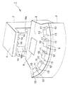
この光学入力手段は、図21(a)に示すように、Y(符号401a),X1(符号401b),X2(符号401c)の3個の赤外線センサーからなる。これら3個のセンサーは、底辺186mm、高さ60mmの二等辺三角形の頂点にそれぞれ配置されている。これらのセンサーは赤外線を送受信することにより比較的近距離の障害物(例えば遊戯者の手)を検出することができる。赤外線センサー401a〜cは、赤外線を送信するとともに物体により反射された赤外線を受信することにより、物体の有無を検知する。すなわち、赤外線センサーは送信機能と受信機能を併せ持つ。これらセンサーの配置は「ブラックジャック」における手の動きを検出するのに適した配置である。
【0107】
図21(b)はセンサー401bと401cとの間にさらに1つのセンサーを設けた例を、図21(c)はセンサー401aの隣にさらに1つのセンサーを設けた例を示す。センサーの動作については後に詳しく説明するが、図21(b)及び図21(c)で追加されたセンサーの役割について簡単に述べる。図21(b)で追加されたセンサーは、左右方向の手の動き(スタンド操作)を確実に検出するためのものである。センサー401b、401、401cの順で(あるいはこの逆)で物体が検出されたときスタンド操作とされる。一方、センサー401a,401,401b(あるいは401c)で物体が検出されたときはスタンド操作と判断されない(例えば、後述のヒット操作と判断される)。また、図21(c)で追加されたセンサーは、手を所定の位置に置く動き(ヒット操作)を確実に検出するためのものである。センサー401a、401のいずれかで物体が検出されたとき、かつ、その検出期間が連続して比較的長い時間であるとき、ヒット操作とされる。センサーを追加することにより、手の位置が多少ずれても確実に検出することができる。
【0108】
一般的に言って、センサーを増やすほど正確な検出が可能になるが、同時にハードウエア構成及び処理ソフトウエアが複雑になる。センサーの数とその配置は、要求される検出精度を満足する範囲で構成がなるべく簡単になるように選択される。図21(a)の3個のセンサーでもほとんどの場合、確実に検出できると考えられるが、スタンド操作あるいはヒット操作のどちらか/両方で誤検出があれば、図21(b)(c)いずれか/両方の配置を採用すればよい。
【0109】
これらのセンサーは、図22に示す意匠パネルの下に配置される。このデザインはセンサーが発する赤外線を遮らないとともに、プレイヤーに対してハンドアクションを行うべき場所を的確に示唆しうるものでなくてはならない。そこで、このパネルは少なくとも赤外線を透過する材質、例えばガラスで作られる。図22のパネルはテーブルのデザインの一部をなすとともに、ゲーム「ブラックジャック」の手の動きの説明も兼ねている。すなわち、横方向に矢印とともに「STAND」とあるが、これは手をこの位置で左右に動かすことで「STAND」(カードの追加不要)動作になることを示す。また、上部に「HIT」とあるが、これは手をこの位置に置くことで「HIT」(カードの追加要)動作になることを示す。センサーY(401a)は、ヒット操作を検出し、センサーX1,X2(401b、c)はスタンド操作を検出するためのものである。なお、センサーの位置が文字や図形と少し離れて配置されているのは、これらの印刷により赤外線が多少遮られるので、これを避けるためである。
【0110】
図25は受光部からの信号の処理系統を示すブロック図である。図26は処理のフローチャートである。
【0111】
図23は同ゲーム機のサテライト部分の操作部付近の詳細を示す平面図であり、図24は同操作部の断面図である。
【0112】
これらの図示す第2の実施の形態において、サテライト3には、光学的操作入力手段401と、操作表示盤29とが設けられている。光学的操作入力手段30の3つのセンサー401a〜cが、入力手段30の上を動く遊戯者の手を検出する。これらセンサーの上には意匠パネル(ガラス板)が設けられている。このガラス板によりセンサーを防護するとともに、赤外線の投射や反射光の入射が容易にできるようにしている。
【0113】
次に動作について説明する。先に説明したように、センサーは、遊戯者の手の動きが「STAND」「HIT」のいずれであるかを検出する。概ね、手を左右に動かせば「STAND」であり、手をやや前に出してかざせば「HIT」である。しかし、手の動かし方、かざす時間等に厳密な規則はない。
【0114】
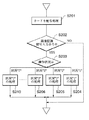
そこで、検知した各センサーの組み合わせにより、以下のように判断する。
【0115】
(1)センサY(401a)のみ検知したときは、ヒット操作とみなす。
【0116】
(2)センサY(401a),X1(401b)が順不同で検出したときは、ヒット操作とみなす。この場合の手の動きは左右の動きを伴うものの、センサYの位置に手が置かれたことから考えてヒット操作と判断すべきである。
【0117】
(3)センサY(401a),X2(401c)が順不同で検出したときは、同様に、ヒット操作とみなす。
【0118】
(4)センサX1(401b),X2(401c)が順不同で検知したときは、スタンド操作とみなす。
【0119】
(5)センサX1(401b),X2(401c)、Y(401a)が順不同で検知したとき、スタンド操作とみなす。この場合の手の動きは左右の動きを主とするものであるから、たとえ、ヒット操作を示すセンサYが検知したとしても、スタンド操作と判断すべきである。
【0120】
(6)センサX1のみ検知したときは、操作とみなさない。また、センサX2のみ検知したときも、操作とみなさない。
【0121】
複数のセンサが検知するときはその間隔が問題となる。一例としてこの間隔を500ミリ秒とすることが考えられる。すなわち、演算手段402は、最初のセンサー検知から500ミリ秒の間、他のセンサーが検知するかどうかを監視し続ける。監視を終了するまでにセンサX1とX2の両方が検知すればスタンドとなる。センサX1とX2のどちらか片方のみ検知し(もしくはどちらも検知せず)、センサYが検知すれば、ヒットとなる。
【0122】
入力内容の判断を適正に行うために、図21のように、センサーX1とX2を左右方向にある程度の距離を置いて配置することが望ましい。つまり、プレイヤーが手をある程度水平方向に動かさなければ、X1とX2の両方が反応しないように配置する。このように配置することにより、センサX1とX2が反応したということは、プライヤーが意図して手を動かしたものと判断でき、センサYの反応の有無に関わらずスタンドの操作をしたものと判断することができる。
【0123】
また、センサYをセンサX1及びX2からある程度の距離置いて配置することが望ましい。この場合において、センサYが反応したということは、プレイヤーが手を上下方向に動かすために敢えて遠方まで手を伸ばしたことを意味し、基本的にはヒットの動作を行ったものと判断してよい。ただし、センサX1及びX2も反応した場合に限り、スタンドの動作のついでにYが反応したものと判断する。
【0124】
上述のスタンド操作とヒット操作を判断するためのハンドアクション評価アルゴリズムは、メインプログラムのリクエストによって動作する。また、メインプログラムがリクエストを終了することで、ハンドアクションを検知するプログラムは動作を終了する。図26にハンドアクション評価アルゴリズムのフローチャートを示す。
【0125】
図26において、センサYが検知したかどうか判断する(S401)。YESの場合、センサY用のフラグをセットするとともに、タイマーを例えば500ミリ秒にセットする(S404)。センサX1、X2フラグが共にセットされたかどうか判断する(S408)。YESの場合、上述のようにスタンド操作と判断し(S412)、評価結果を返す。メインプログラムからのリクエストがまだあるならば(YES)、最初から処理を繰り返す(S414)。一方、S408においてセンサX1、X2フラグがセットされなかったときは、タイマーを調べて設定した時間(500ミリ秒)経過したかどうか判断し、経過していないとき(NO)、最初の処理S401に戻る。経過したとき(YES)、Yフラグがセットされているかどうか調べる(S410)。セットされているとき(YES)、ヒットと判断し(S414)、評価結果を返す。メインプログラムからのリクエストがまだあるならば(YES)、最初から処理を繰り返す(S414)。そうでないとき(NO)、Yフラグをセットするとともに、タイマーを例えば500ミリ秒にセットし(S411)、最初の処理(S401)に戻る。
【0126】
S401でNOの場合、センサーX1が検知したかどうか判断する(S402)。YESの場合、センサX1のフラグをセットするとともに、タイマーを例えば500ミリ秒にセットする(S405)。NOの場合、さらにセンサーX2が検知したかどうか判断する(S403)。YESの場合、センサX2のフラグをセットするとともに、タイマーを例えば500ミリ秒にセットする(S406)。NOの場合、時間の経過に応じて500ミリタイマーから一定数を減算する(S407)。
【0127】
上記(1)「センサY(401a)のみ検知したとき」は、図26のS401、S404,S413の処理によりヒット操作と判断される。
【0128】
上記(2)「センサY(401a),X1(401b)が順不同で検出したとき」は、同じくS401、S404、S413あるいはS402、S405、S413の処理によりヒット操作と判断される。
【0129】
上記(3)「センサY(401a),X2(401c)が順不同で検出したとき」は、同じくS401、S404、S413あるいはS403、S406、S413の処理によりヒット操作と判断される。
【0130】
上記(4)「センサX1(401b),X2(401c)が順不同で検知したとき」は、同じくS402,S405、S412あるいはS403、S406、S412の処理によりスタンド操作と判断される。
【0131】
上記(5)「センサX1(401b),X2(401c)、Y(401a)が順不同で検知したとき」は、S401、S404、S408、S412あるいはS402、S405、S408、S412あるいはS403、S406、S408、S412の処理によりスタンド操作と判断される。
【0132】
上記(6)「センサX1のみ検知したとき」は、S402、S405、S408、S409あるいはS410、S411のルーチンをまわり、操作とみなさない。同様に、センサX2のみ検知したときも、操作とみなさない。
【0133】
なお、1回のプレーについて1回のみヒット操作及びスタンド操作を許容しても、複数回許容しても、どちらでもよい。1回のみ許容する場合は、1回のプレーについて図26のフローチャートの処理は1回のみ行われ、複数回許容する場合は、複数回行われる。例えば、ブラックジャックとは、一人の親(ディーラー)が、1回のゲームで複数の子(プレイヤー)と、それぞれ手の善し悪しを比較して勝負を決するゲームである。プレイヤーが複数いる場合は、ディーラーから見て左手のプレイヤーから順にヒット、スタンドを行う。このとき、ディーラーから見て右手にいるプレーヤーの意思表示の順番は後になる。この実施の形態によれば、順番に関係なくヒットもしくはスタンドの意思表示を行うことができる。このとき、その操作の取り消しを不可能にすれば1回のプレーについて1回のみの操作が可能になり、複数の操作のうち最後のものを有効にすれば、1回のプレーについて複数回の操作が可能になる。後者の場合、自分の順番が来るまでならば、一度表明した意思を変更することができる。
【0134】
以上のように第3の実施の形態によれば、少ない数のセンサにより遊戯者の手の動きを判断できる。また、第3の実施の形態によれば、薄型の光学的入力手段を提供できる。したがって、機器の設計及びデザイン上の自由度が高まり使いやすくなる。さらに、センサ上に、デザイン及びヒット・スタンドの操作位置を表示したガラス板等を設けたので、遊戯者にとって使いやすくなるとともに、操作の確実性が向上する。
【0135】
この光学的入力手段により、例えば、トランプを使用したカジノゲームであるブラックジャックを業務用ゲーム機械で行うにあたり、プレーヤーの意思表示を実際のゲームのように手の動作で行わせることができる。したがって、ゲーム機でありながら、実際にカジノで遊んでいるかのような雰囲気を再現することができる。また、ボタンスイッチを用いる場合と比べて、視線の移動が少なく遊戯者にとって煩わしさが減るという効果もある。
【0136】
また、センサーがパネルの下に設けられ隠されていることから、遊戯者は、筐体のどこにも触れないにもかかわらず、自分の意思がゲーム機に通じる不思議さに驚く。このこともゲームの面白さにつながる。
【0137】
なお、以上の説明において、センサは赤外線を用いるものであったが、これに限らず、例えば超音波を用いるものであってもよい。あるいは単なる受光素子で手の影を検出するものであってもよい。要するに、比較的近い距離(例えば、センサから0cm〜30cm)の手の存在を検出できるものであればよい。
【0138】
また、センサの配置は図21及び図22の例に限らない。ヒットとスタンドの位置が反対であってもよいし、配置は、図21及び図22の2等辺三角形状に限らず、正三角形、直角三角形、不等辺三角形であってもよい。要するに、手の左右方向の動きを検出するための2つのセンサが配置され、さらに、これらを結ぶ直線上以外の位置に別のヒット操作検出用のセンサが設けられていればよい。望ましくは、2つのセンサの間隔はスタンド操作をするときに操作しやすい(手を動かしやすい)程度の距離であり、かつ、2つのセンサとヒット操作検出用のセンサの間隔はスタンド操作をしたときに誤ってヒット操作と判断されない程度である。
【0139】
<第3の実施の形態の変形例>
遊戯者が明らかにゲームのセオリーに反する操作をした場合、例えば1回に限り、遊戯者に対して警告する機能を付加してもよい。これは特に自分の順番が来たときに意思表示をする場合に有効である。
【0140】
このためには図25に示すように演算手段402の判定結果を受けて誤操作かどうか判断し、誤操作のときにその旨の情報を通知する誤操作判定手段404を設ける。誤操作判定手段404は、ゲームの進行状況と遊戯者の意思表示とを比較し、誤操作かどうか判定する。具体的には、それぞれの手の内容を含むゲームの進行状況と取り得る意思表示との対応関係及びその評価(適性か誤りか)を示すテーブルを予め用意しておき、このテーブルに基づき誤操作判定手段404は判定を行う。あるいは、ゲームの進行状況と取り得る意思表示の種類に基づき評価関数を計算し、この評価結果に基づき判定するようにしてもよい。誤操作判定手段404により誤操作と判定されたとき、遊戯者は例えば効果音あるいは画面表示によって警告される。
【0141】
これにより遊戯者は、勘違いや誤操作を犯す危険を減らすことができる。
【0142】
<操作表示盤の断面図>
以上の実施の形態において用いられる操作表示盤の断面図を図27に示す。コイングリッド410から投入されるコインは、シュート412を通ってコイン収集器413で集められる。コイングリッド410は、コインを複数枚重ねた状態で投入できるように、ある程度の高さと幅を有している。従来のスリット状のメダル投入口とは異なり、コイングリッド410を用いるのでテーブル上でチップを扱う感覚でコインを投入できる。
【0143】
また、コイングリッド410の下には、水受け414が設けられている。これは、遊戯者が誤って水とかジュースとかの飲みものをこぼしたときにそれがコイングリッド410から内部の電子装置に侵入することを防止するためのものである。水受け414で受けた水等は排出口414aから装置外に排出される。図示されていないが、排出口414aにはビニール等のパイプが接続されている。
【0144】
【発明の効果】
以上説明したように、本発明によれば、遊戯者の心理状態を遊戯者の音声や動作から把握して、インタラクティブ感覚に優れたゲーム機を提供するができる。
【0145】
また、本発明によれば、遊戯者の音声や動作などの各種の状態を認識することにより、インタラクティブ性に優れたゲーム機を提供することができる。
【0146】
さらに、本発明によれば、遊戯者の内面の微妙な心理状態を、遊戯者の音声や動作を検出し分析することによってゲームの展開に反映させたゲーム機を提供することができる。
【0147】
加えて、本発明によれば、遊戯者の音声の状態に応じてゲーム展開を変化させるゲーム機を提供するができる。
【0148】
また、本発明によれば、遊戯者の動作の状態に応じてゲーム展開を変化させるゲーム機を提供することができる。
【0149】
さらに、本発明によれば、遊戯者から発せられる音声や動作等を介して、遊戯者の内面の微妙な心理状態をシミュレートし、これをゲームの展開に反映させることができる。
【0150】
また、本発明によれば、遊戯者の動作、例えば、手先のカード裁きから、遊戯者の得手不得手等の熟練度をシミュレートし、これをゲームの展開に反映させることも可能である。
【0151】
さらにまた、本発明によれば、かかる動作を検出することにより、キーボードやコントロールパッドのような周辺機器のボタン操作などではどうしても達成されない、例えば、実際のカードゲームに近づけた入力をゲーム機に与え、本物に近い入力に応じた処理をゲーム機に実行させることができる。
【図面の簡単な説明】
【図1】本発明に係るゲーム機の実施の形態を示す斜視図である。
【図2】同実施の形態を示す平面図である。
【図3】同実施の形態の側面図である。
【図4】同実施の形態の処理回路を示すブロック図である。
【図5】音声処理のためのフローチャートである。
【図6】ディスプレイに表示される画面の例を示す説明図である。
【図7】ディスプレイに表示される画面の他の例を示す説明図である。
【図8】画像処理のためのフローチャートである。
【図9】本発明の第2の実施の形態のゲーム機を示す斜視図、
【図10】同第2の実施の形態のゲーム機の正面図である。
【図11】同第2の実施の形態のゲーム機の平面図である。
【図12】同第2の実施の形態のゲーム機の側面図である。
【図13】同第2の実施の形態のゲーム機のサテライト部分の操作部付近の詳細を示す平面図である。
【図14】同第2の実施の形態における操作部の断面図である。
【図15】同第2の実施の形態に係るゲーム機の処理系統の概要を示すブロック図である。
【図16】同第2の実施の形態における受光部からの信号の処理系統を示すブロック図である。
【図17】同第2の実施の形態における発光部から発射された赤外線が受光部で受光される状態を説明するための説明図である。
【図18】同第2の実施の形態における受光部からの信号の処理動作を説明するためのフローチャートである。
【図19】同第2の実施の形態の変形例に係る操作表示盤と光学的操作入力手段との配置の例を示図である。
【図20】本発明の変形例に係る操作表示盤の配置例を示す断面図である。
【図21】同第3の実施の形態における受光部の配置を示す図である。
【図22】同第3の実施の形態における化粧板と受光センサの配置の関係を示す図である。
【図23】同第3の実施の形態のゲーム機のサテライト部分の操作部付近の配置を示す平面図である。
【図24】同第3の実施の形態における操作部の断面図である。
【図25】同第3の実施の形態に係るゲーム機の処理系統の概要を示すブロック図である。
【図26】同第3の実施の形態に係るゲーム機の処理系統のフローチャートを示すブロック図である。
【図27】本発明の実施の形態の操作表示盤の断面図である。
【符号の説明】
1 対面式ゲーム機
2 立設部
3 サテライト
4 張出部
5 筐体部
6 マザーボード
7 ディスプレイ
8 テーブル
10 サテライトディスプレイ
13 マイクロフォン
14 CCDカメラ(撮像素子)
15 音声認識回路
28 肘当て
29 操作表示盤(操作手段)
30 光学的操作入力手段(光学入力手段)
31 発光部
32 受光部
33 ガラス板
35 波形成形回路
325 赤外線センサーユニット[0001]
BACKGROUND OF THE INVENTION
The present invention relates to a game machine, which captures voices and / or actions made by a player, and from the player's voice and / or player's actions, the player's subtle psychological state swings and player's operation commands. This is related to a game machine in which a game processing board is incorporated to diversify game development.
[0002]
[Prior art]
Conventionally, this type of face-to-face game machine imitates a game played by a character (dealer) on the game and at least one player, and processes a game program stored in advance. As the game progresses, a face-to-face game develops.
[0003]
One example of such a face-to-face game machine is described in Japanese Patent No. 2660586. The face-to-face game machine described in this gazette is provided with a projection space provided in the center of the front of the face-to-face game machine, a background provided behind the projection space, and in front of the projection space. A satellite unit having an operation unit for playing a game by looking at the projection space and the satellite display means, a display device that displays a display image on a display surface facing the projection space, and a virtual image of a display image of the display device in the background While the virtual image forming means that transmits the background is provided on the front side, the player can see the composite image that appears to be actually facing the dealer by combining the display image and the background. This is a device for playing a face-to-face game.
[0004]
According to this game machine, in order for the player to experience the game while looking at the composite image that seems to actually face the dealer, the game progresses while feeling the feeling of actually giving out the card from the dealer There are advantages you can do. In this game, the player can operate the operation unit along with the development of the game and give various instructions to the dealer.
[0005]
[Problems to be solved by the invention]
However, in the conventional game machine described above, although there is an advantage that the player can experience the game while seeing the composite image that actually appears to face the dealer, Is information provided only by operating the operation unit, pressing a key on the keyboard device, or pressing the mouse button, so the input information is fixed and it is difficult to convey the delicate psychological state of the player to the game machine. It was. For this reason, there has been a problem that the development of the game is poor and only a game with no change can be executed, such as the behavior and expression of the dealer being uniform. Such a game machine is far from a game sensation that is face-to-face, that is, rich in interactive relations (interactive characteristics) between the game machine and the player.
[0006]
Accordingly, the present inventors have completed the present invention for the purpose of providing a game machine with an excellent interactive feeling by grasping the player's psychological state from the player's voice and actions. Another object of the present invention is to provide a game machine with excellent interactivity by recognizing various states such as a player's voice and actions. Another object of the present invention is to provide a game machine in which the delicate psychological state of the inner surface of the player is reflected in the development of the game by detecting and analyzing the player's voice and actions.
[0007]
Another object of the present invention is to provide a game machine that changes the game development according to the voice state of the player. Still another object of the present invention is to provide a game machine that changes the game development according to the state of action of the player.
[0008]
[Means for Solving the Problems]
The game machine according to the present invention is recognized as a means for recognizing sound and / or action generated by a player in a game machine that executes a predetermined game program in accordance with input information from the player. Means for determining the state of voice and action, and processing means for causing the game machine to perform a response processing operation in accordance with the state of voice and action.
[0009]
The present invention is characterized by simulating a subtle psychological state on the inner surface of a player through voices, actions, etc. emitted from the player and reflecting this in the development of the game. In addition, it is characterized by simulating the proficiency level of the player's strengths and weaknesses from the player's actions, for example, card cutting at the hand, and reflecting this in the development of the game. The present invention also provides the game machine with an input close to an actual card game, for example, which cannot be achieved by detecting button operations on peripheral devices such as a keyboard and control pad. The game machine is caused to execute processing corresponding to an input close to the real thing.
[0010]
In the present invention, various features such as voice level, tone, intonation, and tone are extracted from the voice. Various characteristics such as the speed of movement, the width of movement, and the time of movement are extracted from the movement of the player. The movement is mainly a movement of the hand, but is not limited to this, and may be a movement of a part of the player's body. This movement includes the facial expression of the player.
[0011]
Preferably, an interactive game processing means with a player is provided.
[0012]
Preferably, a voice signal converting means for converting a voice uttered by a player into a voice signal, a voice recognition means for recognizing the voice signal and outputting a recognition signal corresponding to the recognition result, and depending on the situation of the recognition signal And processing means for developing game contents.
[0013]
Preferably, the processing means develops the video of the game and / or the audio of the game in response to the recognition command.
[0014]
Preferably, the voice recognition means recognizes a voice signal pattern and / or recognizes a voice signal level.
[0015]
Preferably, the voice recognition unit stores various voice patterns in advance, and determines which of the voice patterns approximates the input voice signal.
[0016]
The game machine according to the present invention comprises an image pickup means for converting the player's movement into a video signal, an image recognition means for recognizing the video signal and outputting an image recognition signal, and a status of the image recognition signal. And processing means for developing the game.
[0017]
Preferably, the imaging means and the image recognition means can be used in a time division manner.
[0018]
Preferably, the imaging means acquires the action of the player's hand.
[0019]
Preferably, the image pickup means includes a MOS type image pickup device capable of condensing a video by a lens and changing it into a video signal, and the image recognition means recognizes an image of the video signal from the MOS type image pickup device.
[0020]
The game machine according to the present invention includes an input means for detecting an action of the player to make an electric signal, an arithmetic means for calculating the action of the player based on the electric signal from the input means, The processing means which develops a game according to the calculation result is provided.
[0021]
Preferably, the input unit includes a light emitting unit that emits infrared rays into a predetermined space, and a light receiving unit that receives reflected light of the infrared rays according to a player's movement in the predetermined space and converts the infrared light into an electrical signal. .
[0022]
Preferably, the light receiving unit includes a dark box and an infrared sensor unit having an infrared element provided in the dark box and divided into a plurality of parts.
[0023]
Preferably, the movement of the player in the predetermined space is to acquire the movement of the player's hand.
[0024]
Preferably, the input unit includes a first detection unit including at least two sensors and a second detection unit including at least one sensor, and the first detection unit is formed by the second detection unit. The calculation means detects a first movement of the player's hand based on the output of the first detection unit, and the second movement of the player's hand based on the output of the second detection unit. Is detected.
[0025]
Preferably, the first movement is an action of moving the hand left and right, and the second movement is an action of placing the hand in a predetermined position.
[0026]
Preferably, a panel for explaining the movement of the hand is provided on the input means, and the sensor detects the movement of the player's hand through the panel.
[0027]
The game machine according to the present invention includes an optical input means for detecting an action of the player to generate an electric signal, a calculation means for calculating the action of the player based on the electric signal from the optical input means, and a player Operating means for directly operating, and processing means for developing a game in response to a calculation result from the calculation means or an operation command from the operation display panel.
[0028]
Preferably, the operation means is provided closer to the player than the optical input means.
[0029]
Preferably, the operation means is arranged with an inclination toward the lower side as it goes to the player side.
[0030]
DETAILED DESCRIPTION OF THE INVENTION
Hereinafter, embodiments according to the present invention will be described with reference to the drawings.
[0031]
<First Embodiment>
1 to 3 are diagrams for explaining a first embodiment according to the present invention. FIG. 1 is a perspective view of the apparatus, FIG. 2 is a plan view of a part of the apparatus, and FIG. 3 is a side view showing the apparatus in a partially broken view.
[0032]
In these figures, the face-to-
[0033]
A
[0034]
The
[0035]
The
[0036]
Are provided with
[0037]
[0038]
FIG. 4 is a block diagram showing an outline of a processing system of the game machine according to the first embodiment of the present invention. The game machine main body includes a
[0039]
The
[0040]
The
[0041]
Further, the
[0042]
The
[0043]
Based on the voice recognition signal or the image recognition signal received from the
[0044]
The video block 21 includes a first VPD (Video Display Processor) 220 that draws a polygon screen to be overwritten on a character and background image composed of polygon data of a TV game, and a scroll background screen drawing and priority (display wired ranking). And a
[0045]
The
[0046]
On the other hand, the
[0047]
For the
[0048]
When the display image data is in the pallet format, the
[0049]
The sound block 22 includes a
[0050]
The subsystem 23 includes a CD-ROM drive 19b, a CD-I /
[0051]
The
[0052]
[Operation as a voice processor]
The operation of the embodiment thus configured will be described with reference to FIGS. 5 to 7 based on FIG. FIG. 5 is a flowchart for explaining the operation of the game machine as a sound processing device. 6 and 7 are explanatory diagrams showing examples of screens displayed on the display by the processing by the voice processing apparatus.
[0053]
Now, it is assumed that a character imitating a dealer displayed on the
[0054]
The
[0055]
Here, the
[0056]
<Operation of audio signal level “1” when the same card is dealt>
For example, it is assumed that the player utters a sound when the “A” card and the “10” card as shown in FIG. 6A are displayed on the
[0057]
That is, when the voice recognition signal is at level “1” (S103; “1”), the
[0058]
<Operation of audio signal level “2” when the same card is dealt>
Similarly, when the player's
[0059]
<Operation of audio signal level “3” when the same card is dealt>
Similarly, when the player's
[0060]
The above three operations are performed, but when the development is completed (S104 to S106), the
[0061]
Thus, by applying the voice processing device to the face-to-face game machine, even if the same card is dealt, due to the player's psychological situation, that is, the player has won the game and is in good shape Sometimes the psychological state is uplifting and the sound level tends to be high and the tone tends to be high. Therefore, by reflecting the tone of the voice generated by the player in the game development of the game machine, the player can be operated as if the player can interact with the dealer displayed on the
[0062]
In the first embodiment, the
[0063]
In the first embodiment, the video is changed as the development of the game by the voice recognition signal. However, the sound effect of the game may be changed according to the voice recognition signal.
[0064]
[First Embodiment as Image Processing Apparatus]
FIG. 8 is a flowchart for explaining the operation of the image processing apparatus. First, as described above, the
[0065]
The video signals of the operation surface obtained by these
[0066]
The movement of the player's hand on the operation surface is captured by the
[0067]
That is, the
[0068]
Next, the
[0069]
Therefore, the
[0070]
As described above, in the present image processing apparatus, the subtle movement of the player on the operation surface is captured by, for example, the
[0071]
In the first embodiment, the situation is simply described as “1” to “7”, but the present invention is not limited to this, and the situation may be classified in more detail. In this case, more detailed operation commands can be developed in the game.
[0072]
In the first embodiment, the image recognition processing method using the combination of the
[0073]
<Second Embodiment>
9 to 18 are for explaining the second embodiment of the present invention. Here, FIG. 9 is a perspective view showing a game machine according to the second embodiment of the present invention, FIG. 10 is a front view of the game machine, FIG. 11 is a plan view of the game machine, and FIG. It is a side view.
[0074]
In the second embodiment shown in these drawings, the same components as those in the first embodiment are denoted by the same reference numerals, and description thereof is omitted. The face-to-
[0075]
FIG. 13 is a plan view showing details of the vicinity of the operation portion of the satellite portion of the game machine, and FIG. 14 is a cross-sectional view of the operation portion.
[0076]
In the second embodiment shown in the drawings, the
[0077]
First, the structure of the
[0078]
Next, the optical operation input means 30 will be described. The optical operation input means 30 is roughly divided into a
[0079]
On the
[0080]
The
[0081]
In addition, a
[0082]
FIG. 15 is a block diagram showing an outline of a processing system of the game machine according to the second embodiment. The game machine main body according to the second embodiment includes a
[0083]
In the game machine according to the second embodiment, instead of the
[0084]
A signal from each
[0085]
FIG. 16 is a block diagram illustrating a processing system for signals from the
[0086]
That is, the calculation means 250 calculates the table from the detection signal value of each
[0087]
The arithmetic means 250 and the game processing means 254 are realized by the
[0088]
The operation of the second embodiment will be described with reference to FIGS. Here, FIG. 17 is an explanatory diagram for explaining a state in which infrared light emitted from the light emitting unit is received by the light receiving unit. FIG. 18 is a flowchart for explaining the processing operation of the signal from the light receiving unit.
[0089]
In FIG. 17, the infrared RL emitted from the two
[0090]
On the other hand, as shown in FIGS. 14 and 17, the player places the
[0091]
Then, the infrared ray RL emitted from the
[0092]
Signals from these
[0093]
As a result of calculating the movement of the player's
[0094]
As a result of calculating the movement of the player's
[0095]
<Modification of Second Embodiment>
In the second embodiment, the game processing means 254 is caused to execute two processes according to the movement of the player's
[0096]
Further, in the second embodiment, the point of the game process by voice is not described, but the game process by voice is also performed as in the first embodiment.
[0097]
Furthermore, in the said 2nd Embodiment, although 2 LED311 of the
[0098]
<Other variations>
FIGS. 19A and 19B show examples of the arrangement of the operation display panel and the optical operation input means.
[0099]
In this modification, as shown in FIG. 19A, the
[0100]
On the other hand, as shown in FIG. 19B, an example different from the above modification is that the optical operation input means 30 is arranged on the player side, and the
[0101]
FIG. 20 is a cross-sectional view showing an arrangement example of the operation display panel. As can be seen from FIG. 20, it is desirable that the
[0102]
As described above, even if the
[0103]
<Another modification>
When the image processing apparatus according to each of the embodiments described above is applied to a game machine, an operation command can be given to the game development by a player's gesture or the like, so that the game machine can be made closer to reality.
[0104]
In each of the above embodiments, the operation of the sound processing device and the operation of the image processing device have been described separately, but both may be integrated. In this case, it is needless to say that an interpersonal game device with further improved interactive feeling can be obtained.
[0105]
<Third Embodiment>
In this embodiment, a simple optical operation input means (optical input means) that can easily discriminate the movement of the player's arm or the like, which is different from the second embodiment, will be described. This optical input means is arranged in the same manner as in the second embodiment.
[0106]
As shown in FIG. 21A, the optical input means is composed of three infrared sensors Y (reference numeral 401a), X1 (reference numeral 401b), and X2 (reference numeral 401c). These three sensors are respectively arranged at the vertices of an isosceles triangle having a base of 186 mm and a height of 60 mm. These sensors can detect an obstacle (for example, a player's hand) at a relatively short distance by transmitting and receiving infrared rays. The
[0107]
FIG. 21B shows an example in which one more sensor is provided between the
[0108]
Generally speaking, increasing the number of sensors enables more accurate detection, but at the same time complicates the hardware configuration and processing software. The number of sensors and their arrangement are selected so that the configuration is as simple as possible within a range that satisfies the required detection accuracy. In most cases, the three sensors shown in FIG. 21 (a) are considered to be reliably detected. However, if there is a false detection in either / both the stand operation or the hit operation, either of FIG. 21 (b) (c) Or both arrangements may be employed.
[0109]
These sensors are arranged under the design panel shown in FIG. This design should not block the infrared rays emitted by the sensor, and should be able to accurately suggest where to perform hand actions for the player. Therefore, this panel is made of a material that transmits at least infrared rays, for example, glass. The panel in FIG. 22 forms part of the table design and also explains the hand movement of the game “Blackjack”. That is, “STAND” is displayed along with an arrow in the horizontal direction, and this indicates that a “STAND” (card addition unnecessary) operation is performed by moving the hand left and right at this position. In addition, “HIT” is displayed at the top, which indicates that a “HIT” (addition of a card) operation is performed by placing the hand at this position. The sensor Y (401a) detects a hit operation, and the sensors X1 and X2 (401b, c) are for detecting a stand operation. The reason why the position of the sensor is arranged slightly apart from the characters and figures is to avoid this because the infrared rays are somewhat blocked by these printings.
[0110]
FIG. 25 is a block diagram showing a processing system of signals from the light receiving unit. FIG. 26 is a flowchart of the process.
[0111]
FIG. 23 is a plan view showing details of the vicinity of the operation portion of the satellite portion of the game machine, and FIG. 24 is a cross-sectional view of the operation portion.
[0112]
In the second embodiment shown in the drawings, the
[0113]
Next, the operation will be described. As described above, the sensor detects whether the movement of the player's hand is “STAND” or “HIT”. Generally, it is “STAND” when the hand is moved to the left and right, and “HIT” when the hand is moved slightly forward. However, there are no strict rules about how to move the hand, how long to hold it.
[0114]
Therefore, the following determination is made based on the combination of the detected sensors.
[0115]
(1) When only the sensor Y (401a) is detected, it is regarded as a hit operation.
[0116]
(2) When the sensors Y (401a) and X1 (401b) detect in random order, they are regarded as hit operations. Although the movement of the hand in this case is accompanied by a left-right movement, it should be determined as a hit operation in consideration of the hand placed at the position of the sensor Y.
[0117]
(3) When the sensors Y (401a) and X2 (401c) detect in random order, they are similarly regarded as hit operations.
[0118]
(4) When the sensors X1 (401b) and X2 (401c) detect in any order, it is regarded as a stand operation.
[0119]
(5) When the sensors X1 (401b), X2 (401c), and Y (401a) detect in any order, it is regarded as a stand operation. Since the hand movement in this case is mainly left and right, even if the sensor Y indicating a hit operation detects it, it should be determined as a stand operation.
[0120]
(6) When only the sensor X1 is detected, it is not regarded as an operation. Further, when only the sensor X2 is detected, it is not regarded as an operation.
[0121]
When multiple sensors detect, the interval becomes a problem. As an example, this interval may be set to 500 milliseconds. That is, the
[0122]
In order to properly determine the input contents, it is desirable to arrange the sensors X1 and X2 at a certain distance in the left-right direction as shown in FIG. In other words, if the player does not move his / her hand to a certain extent in the horizontal direction, both the X1 and X2 are arranged so as not to react. By arranging in this way, it can be determined that the sensors X1 and X2 have reacted, that the pliers have intentionally moved their hands, and that it has been determined that the stand has been operated regardless of whether or not the sensor Y has reacted. can do.
[0123]
Further, it is desirable to arrange the sensor Y at a certain distance from the sensors X1 and X2. In this case, the fact that the sensor Y has responded means that the player has extended his / her hand far in order to move his / her hand up and down, and basically it is determined that the player has performed a hit operation. Good. However, only when the sensors X1 and X2 have also reacted, it is determined that Y has reacted following the operation of the stand.
[0124]
The hand action evaluation algorithm for determining the stand operation and the hit operation described above operates according to a request from the main program. Further, when the main program terminates the request, the program for detecting the hand action terminates the operation. FIG. 26 shows a flowchart of the hand action evaluation algorithm.
[0125]
In FIG. 26, it is determined whether the sensor Y has detected (S401). If YES, the flag for sensor Y is set and the timer is set to 500 milliseconds, for example (S404). It is determined whether both the sensor X1 and X2 flags are set (S408). If YES, the stand operation is determined as described above (S412), and the evaluation result is returned. If there is still a request from the main program (YES), the process is repeated from the beginning (S414). On the other hand, when the sensors X1 and X2 flags are not set in S408, the timer is checked to determine whether or not the set time (500 milliseconds) has elapsed. If not (NO), the first process S401 is performed. Return. When the time has elapsed (YES), it is checked whether the Y flag is set (S410). When it is set (YES), it is determined as a hit (S414), and the evaluation result is returned. If there is still a request from the main program (YES), the process is repeated from the beginning (S414). If not (NO), the Y flag is set and the timer is set to, for example, 500 milliseconds (S411), and the process returns to the first process (S401).
[0126]
If NO in S401, it is determined whether the sensor X1 has been detected (S402). In the case of YES, the flag of the sensor X1 is set, and the timer is set to 500 milliseconds, for example (S405). In the case of NO, it is further determined whether or not the sensor X2 has been detected (S403). In the case of YES, the flag of the sensor X2 is set, and the timer is set to 500 milliseconds, for example (S406). In the case of NO, a certain number is subtracted from the 500 millitimer as time passes (S407).
[0127]
The above (1) “when only sensor Y (401a) is detected” is determined to be a hit operation by the processing of S401, S404, and S413 in FIG.
[0128]
The above (2) “when the sensors Y (401a) and X1 (401b) detect in random order” is similarly determined as a hit operation by the processing of S401, S404, S413 or S402, S405, S413.
[0129]
The above (3) “when the sensors Y (401a) and X2 (401c) detect in random order” is similarly determined as a hit operation by the processing of S401, S404, S413 or S403, S406, S413.
[0130]
The above (4) “when the sensors X1 (401b) and X2 (401c) detect in random order” is determined as the stand operation by the processes of S402, S405, S412 or S403, S406, S412.
[0131]
The above (5) “when sensors X1 (401b), X2 (401c), Y (401a) are detected in no particular order” is S401, S404, S408, S412 or S402, S405, S408, S412 or S403, S406, S408. , S412 is determined as a stand operation.
[0132]
The above (6) “when only sensor X1 is detected” goes through the routine of S402, S405, S408, S409 or S410, S411, and is not regarded as an operation. Similarly, when only the sensor X2 is detected, it is not regarded as an operation.
[0133]
It should be noted that either a hit operation and a stand operation may be permitted only once or a plurality of times may be permitted per play. When one time is permitted, the process of the flowchart of FIG. 26 is performed only once for one play, and when multiple times are permitted, the process is performed a plurality of times. For example, blackjack is a game in which a parent (dealer) determines a game by comparing the quality of each hand with a plurality of children (players) in one game. If there are multiple players, hit and stand in order from the player on the left as viewed from the dealer. At this time, the player's intention display order on the right side as viewed from the dealer is later. According to this embodiment, it is possible to display the intention of hit or stand regardless of the order. At this time, if it is impossible to cancel the operation, only one operation can be performed for one play, and if the last one of a plurality of operations is enabled, multiple operations can be performed for one play. Operation becomes possible. In the latter case, you can change your intention once you have your turn.
[0134]
As described above, according to the third embodiment, a player's hand movement can be determined by a small number of sensors. Further, according to the third embodiment, a thin optical input means can be provided. Therefore, the degree of freedom in design and design of the equipment is increased, and it is easy to use. Furthermore, since a glass plate or the like displaying the design and the operation position of the hit stand is provided on the sensor, it is easy for the player to use and the reliability of the operation is improved.
[0135]
With this optical input means, for example, when playing blackjack, which is a casino game using playing cards, with an arcade game machine, the player's intention can be displayed by hand as in an actual game. Therefore, it is possible to reproduce the atmosphere as if playing a casino in spite of being a game machine. Further, as compared with the case where a button switch is used, there is an effect that the movement of the line of sight is less and the trouble for the player is reduced.
[0136]
In addition, since the sensor is provided under the panel and is hidden, the player is surprised at the wonder that his intention can be communicated with the game machine even though he does not touch anywhere on the housing. This also leads to the fun of the game.
[0137]
In the above description, the sensor uses infrared rays. However, the present invention is not limited to this. For example, ultrasonic waves may be used. Alternatively, the shadow of the hand may be detected by a simple light receiving element. In short, any device capable of detecting the presence of a hand at a relatively close distance (for example, 0 cm to 30 cm from the sensor) may be used.
[0138]
Further, the arrangement of the sensors is not limited to the examples of FIGS. The positions of the hit and the stand may be opposite, and the arrangement is not limited to the isosceles triangle shape of FIGS. 21 and 22, but may be a regular triangle, a right triangle, or an unequal triangle. In short, it is only necessary that two sensors for detecting the movement of the hand in the left-right direction are arranged, and another hit operation detection sensor is provided at a position other than the straight line connecting them. Desirably, the distance between the two sensors is a distance that is easy to operate (easy to move the hand) when performing the stand operation, and the distance between the two sensors and the sensor for detecting the hit operation is when the stand operation is performed. In such a case, the hit operation is not mistakenly determined.
[0139]
<Modification of Third Embodiment>
When the player has made an operation that is clearly contrary to the game theory, for example, a function may be added that warns the player only once. This is particularly effective when expressing intentions when the turn of the person comes.
[0140]
For this purpose, as shown in FIG. 25, there is provided an erroneous operation determination means 404 that receives the determination result of the calculation means 402 to determine whether or not an erroneous operation has occurred, and notifies information to that effect when an erroneous operation occurs. The erroneous operation determination means 404 compares the progress of the game with the player's intention display, and determines whether or not there is an erroneous operation. Specifically, a table showing the correspondence between the progress of the game including the contents of each hand and possible intention indications and its evaluation (appropriate or incorrect) is prepared in advance, and erroneous operation determination based on this table Means 404 makes the determination. Alternatively, an evaluation function may be calculated based on the progress of the game and the type of intention display that can be taken, and determination may be made based on the evaluation result. When the erroneous operation determination means 404 determines that the operation is incorrect, the player is warned, for example, by sound effects or screen display.
[0141]
As a result, the player can reduce the risk of misunderstanding and misoperation.
[0142]
<Cross section of operation display panel>
A cross-sectional view of the operation display panel used in the above embodiment is shown in FIG. Coins inserted from the
[0143]
A water receiver 414 is provided below the
[0144]
【The invention's effect】
As described above, according to the present invention, it is possible to provide a game machine with an excellent interactive feeling by grasping the player's psychological state from the player's voice and actions.
[0145]
In addition, according to the present invention, it is possible to provide a game machine with excellent interactivity by recognizing various states such as a player's voice and actions.
[0146]
Furthermore, according to the present invention, it is possible to provide a game machine in which the delicate psychological state of the inner surface of the player is reflected in the game development by detecting and analyzing the player's voice and actions.
[0147]
In addition, according to the present invention, it is possible to provide a game machine that changes the game development according to the voice state of the player.
[0148]
Moreover, according to this invention, the game machine which changes a game expansion | deployment according to the state of a player's operation | movement can be provided.
[0149]
Furthermore, according to the present invention, it is possible to simulate a subtle psychological state on the inner surface of the player through voices, actions, etc. emitted from the player and reflect this in the development of the game.
[0150]
In addition, according to the present invention, it is possible to simulate the skill level of the player's weaknesses and the like based on the player's actions, for example, card cutting at the hand, and reflect this in the development of the game.
[0151]
Furthermore, according to the present invention, by detecting such an operation, for example, it is not possible to achieve by a button operation of a peripheral device such as a keyboard or a control pad. For example, an input close to an actual card game is given to the game machine. It is possible to cause the game machine to execute a process according to an input close to the real thing.
[Brief description of the drawings]
FIG. 1 is a perspective view showing an embodiment of a game machine according to the present invention.
FIG. 2 is a plan view showing the same embodiment;
FIG. 3 is a side view of the same embodiment;
FIG. 4 is a block diagram showing a processing circuit of the same embodiment;
FIG. 5 is a flowchart for voice processing.
FIG. 6 is an explanatory diagram illustrating an example of a screen displayed on the display.
FIG. 7 is an explanatory diagram showing another example of a screen displayed on the display.
FIG. 8 is a flowchart for image processing.
FIG. 9 is a perspective view showing a game machine according to a second embodiment of the present invention;
FIG. 10 is a front view of the game machine of the second embodiment.
FIG. 11 is a plan view of the game machine according to the second embodiment.
FIG. 12 is a side view of the game machine of the second embodiment.
FIG. 13 is a plan view showing details in the vicinity of the operation unit of the satellite portion of the game machine of the second embodiment.
FIG. 14 is a cross-sectional view of an operation unit according to the second embodiment.
FIG. 15 is a block diagram showing an outline of a processing system of the game machine according to the second embodiment.
FIG. 16 is a block diagram showing a processing system of signals from a light receiving unit in the second embodiment.
FIG. 17 is an explanatory diagram for explaining a state in which infrared light emitted from a light emitting unit is received by a light receiving unit in the second embodiment;
FIG. 18 is a flowchart for explaining a processing operation of a signal from a light receiving unit in the second embodiment.
FIG. 19 is a view showing an example of the arrangement of an operation display board and optical operation input means according to a modification of the second embodiment.
FIG. 20 is a cross-sectional view showing an arrangement example of an operation display panel according to a modification of the present invention.
FIG. 21 is a diagram showing an arrangement of light receiving portions in the third embodiment.
FIG. 22 is a diagram showing the relationship between the arrangement of the decorative plate and the light receiving sensor in the third embodiment.
FIG. 23 is a plan view showing an arrangement in the vicinity of the operation unit of the satellite portion of the game machine of the third embodiment.
FIG. 24 is a cross-sectional view of an operation unit according to the third embodiment.
FIG. 25 is a block diagram showing an outline of a processing system of the game machine according to the third embodiment.
FIG. 26 is a block diagram showing a flowchart of a processing system of the game machine according to the third embodiment.
FIG. 27 is a cross-sectional view of the operation display panel according to the embodiment of the present invention.
[Explanation of symbols]
1 face-to-face game machine
2 Standing part
3 Satellite
4 Overhang
5 Case
6 Motherboard
7 Display
8 tables
10 Satellite display
13 Microphone
14 CCD camera (image sensor)
15 Speech recognition circuit
28 Elbow pads
29 Operation display panel (operation means)
30 Optical operation input means (optical input means)
31 Light emitting part
32 Receiver
33 Glass plate
35 Waveform shaping circuit
325 Infrared sensor unit
Claims (2)
前記遊戯者がボタンを押してゲーム操作を行うための操作手段と、
前記入力手段が前記操作手段を挟んで前記遊戯者と反対側に配置された操作テーブルと、
前記入力手段からの電気信号に基づいて前記遊戯者の動作を演算する演算手段と、
前記演算手段による演算結果に応じたゲーム処理を実行するゲーム処理手段と、
を備え、
前記入力手段は、少なくとも2つのセンサを含む第1検出部、及び、少なくとも1つのセンサを含む第2検出部を有しており、
前記第2検出部は、前記第1検出部のセンサ間を結ぶ直線上に配置されておらず、
前記演算手段は、前記第1検出部からの出力信号に基づいて前記遊戯者の手の第1の動きを検出し、かつ、前記第2検出部からの出力信号に基づいて前記遊戯者の手の第2の動きを検出するものであり、
前記発光部及び前記受光部の上方に配置されており、前記赤外線及び該赤外線の反射光を透過可能に形成されており、かつ、前記ゲームにおいて前記遊戯者に行わせる手の動作を説明するためのデザインが表示されたパネルを備えており、
前記発光部から上方に向けて発射された前記赤外線が前記パネルを透過し、該パネルの上方の空間において生じた該赤外線の反射光が該パネルを透過して前記受光部に受光されることにより、前記遊戯者の手が前記パネルに接触することなく前記遊戯者の手の動きが検出される、
ゲーム機。An input unit having a light emitting unit that emits infrared rays into a predetermined space, and a light receiving unit that receives the reflected light of the infrared rays according to a player's movement in the predetermined space and converts it into an electrical signal;
Operation means for the player to perform a game operation by pressing a button;
An operation table in which the input means is disposed on the opposite side of the player across the operation means;
Arithmetic means for calculating the player's action based on an electric signal from the input means;
Game processing means for executing a game process according to a calculation result by the calculation means;
Equipped with a,
The input means includes a first detection unit including at least two sensors, and a second detection unit including at least one sensor,
The second detection unit is not arranged on a straight line connecting the sensors of the first detection unit,
The calculation means detects a first movement of the player's hand based on an output signal from the first detection unit, and detects the player's hand based on an output signal from the second detection unit. der detects the second motion is,
In order to explain the operation of the hand that is disposed above the light emitting unit and the light receiving unit, is formed so as to be able to transmit the infrared rays and the reflected light of the infrared rays, and that the player performs in the game. Panel with the design of
The infrared rays emitted upward from the light emitting unit are transmitted through the panel, and the reflected light of the infrared rays generated in the space above the panel is transmitted through the panel and received by the light receiving unit. , Movement of the player's hand is detected without the player's hand touching the panel ;
Gate arm machine.
請求項1記載のゲーム機。The operation means is disposed below the upper surface of the input means.
1 Symbol placement game machine according to claim.
Priority Applications (5)
| Application Number | Priority Date | Filing Date | Title |
|---|---|---|---|
| JP20153498A JP3899498B2 (en) | 1997-11-12 | 1998-07-16 | game machine |
| US09/179,748 US6607443B1 (en) | 1997-11-12 | 1998-10-28 | Game device |
| TW087118829A TW408027B (en) | 1997-11-12 | 1998-11-11 | Game device |
| BE9800824A BE1012301A3 (en) | 1997-11-12 | 1998-11-12 | Game device. |
| US10/457,086 US7128651B2 (en) | 1997-11-12 | 2003-06-09 | Card game for displaying images based on sound recognition |
Applications Claiming Priority (5)
| Application Number | Priority Date | Filing Date | Title |
|---|---|---|---|
| JP9-310771 | 1997-11-12 | ||
| JP31077197 | 1997-11-12 | ||
| JP3526098 | 1998-02-17 | ||
| JP10-35260 | 1998-02-17 | ||
| JP20153498A JP3899498B2 (en) | 1997-11-12 | 1998-07-16 | game machine |
Publications (2)
| Publication Number | Publication Date |
|---|---|
| JPH11300034A JPH11300034A (en) | 1999-11-02 |
| JP3899498B2 true JP3899498B2 (en) | 2007-03-28 |
Family
ID=27288702
Family Applications (1)
| Application Number | Title | Priority Date | Filing Date |
|---|---|---|---|
| JP20153498A Expired - Lifetime JP3899498B2 (en) | 1997-11-12 | 1998-07-16 | game machine |
Country Status (4)
| Country | Link |
|---|---|
| US (2) | US6607443B1 (en) |
| JP (1) | JP3899498B2 (en) |
| BE (1) | BE1012301A3 (en) |
| TW (1) | TW408027B (en) |
Families Citing this family (127)
| Publication number | Priority date | Publication date | Assignee | Title |
|---|---|---|---|---|
| US7510190B2 (en) * | 1993-02-25 | 2009-03-31 | Shuffle Master, Inc. | High-low poker wagering games |
| US8272958B2 (en) * | 2004-01-26 | 2012-09-25 | Shuffle Master, Inc. | Automated multiplayer game table with unique image feed of dealer |
| US7661676B2 (en) * | 2001-09-28 | 2010-02-16 | Shuffle Master, Incorporated | Card shuffler with reading capability integrated into multiplayer automated gaming table |
| US20090075724A1 (en) * | 1993-02-25 | 2009-03-19 | Shuffle Master, Inc. | Wireless bet withdrawal gaming system |
| US20080096659A1 (en) * | 2006-10-23 | 2008-04-24 | Kreloff Shawn D | Wireless communal gaming system |
| US20050164759A1 (en) * | 2004-01-26 | 2005-07-28 | Shuffle Master, Inc. | Electronic gaming machine with architecture supporting a virtual dealer and virtual cards |
| US7367563B2 (en) * | 1993-02-25 | 2008-05-06 | Shuffle Master, Inc. | Interactive simulated stud poker apparatus and method |
| US20060284378A1 (en) * | 2002-05-20 | 2006-12-21 | Shuffle Master, Inc. | Poker game with blind bet and player selectable play wager |
| US7387300B2 (en) * | 1994-07-22 | 2008-06-17 | Shuffle Master, Inc. | Player-banked four card poker game |
| US20050242506A1 (en) * | 1994-07-22 | 2005-11-03 | Shuffle Master, Inc. | Poker game variation with variable size wagers and play against a pay table |
| US7331579B2 (en) * | 1995-07-19 | 2008-02-19 | Shuffle Master, Inc. | Poker game with dealer disqualifying hand |
| US5685774A (en) * | 1994-07-22 | 1997-11-11 | Webb; Derek J. | Method of playing card games |
| US7628689B2 (en) * | 1994-07-22 | 2009-12-08 | Shuffle Master, Inc. | Poker game with blind bet and player selectable play wager |
| US20070210520A1 (en) * | 1994-07-22 | 2007-09-13 | Shuffle Master, Inc. | Method of playing card games |
| US20020195775A1 (en) * | 1994-07-22 | 2002-12-26 | Shuffle Master, Inc. | Four card poker and associated games |
| US5688174A (en) * | 1995-10-06 | 1997-11-18 | Kennedy; Julian J. | Multiplayer interactive video gaming device |
| JP3899498B2 (en) * | 1997-11-12 | 2007-03-28 | 株式会社セガ | game machine |
| JP2001070640A (en) | 1999-09-07 | 2001-03-21 | Konami Co Ltd | Game machine |
| JP3363121B2 (en) * | 2000-02-23 | 2003-01-08 | コナミ株式会社 | Dance game equipment |
| JP3329786B2 (en) * | 2000-02-29 | 2002-09-30 | コナミ株式会社 | Dance game equipment |
| JP3736440B2 (en) | 2001-02-02 | 2006-01-18 | 株式会社セガ | Card and card game device |
| JP3491833B2 (en) * | 2001-02-16 | 2004-01-26 | 株式会社ナムコ | Program, information storage medium and game device |
| US7533886B2 (en) * | 2001-03-19 | 2009-05-19 | Shuffle Master, Inc. | Play four poker with bad beat feature |
| US20070024005A1 (en) * | 2002-05-20 | 2007-02-01 | Shuffle Master, Inc. | Four card poker game with variable wager |
| US20160136511A9 (en) | 2002-05-20 | 2016-05-19 | Bally Gaming, Inc. | Four Card Poker Game with Variable Wager |
| US20070298854A1 (en) * | 2002-05-20 | 2007-12-27 | Yoseloff Mark L | Six-card poker game |
| US20090295091A1 (en) * | 2002-05-20 | 2009-12-03 | Abbott Eric L | Poker games with player qualification |
| JP3842697B2 (en) | 2002-06-11 | 2006-11-08 | アルゼ株式会社 | Game machine, server and program |
| JP2004049312A (en) | 2002-07-16 | 2004-02-19 | Aruze Corp | Game machine, server, and program |
| JP2004049313A (en) | 2002-07-16 | 2004-02-19 | Aruze Corp | Game machine, server, and program |
| US20070260517A1 (en) * | 2006-05-08 | 2007-11-08 | Gary Zalewski | Profile detection |
| US20070061413A1 (en) * | 2005-09-15 | 2007-03-15 | Larsen Eric J | System and method for obtaining user information from voices |
| US20070261077A1 (en) * | 2006-05-08 | 2007-11-08 | Gary Zalewski | Using audio/visual environment to select ads on game platform |
| US7815507B2 (en) * | 2004-06-18 | 2010-10-19 | Igt | Game machine user interface using a non-contact eye motion recognition device |
| US8460103B2 (en) | 2004-06-18 | 2013-06-11 | Igt | Gesture controlled casino gaming system |
| JP3939613B2 (en) * | 2002-08-21 | 2007-07-04 | 株式会社ピートゥピーエー | Race game apparatus, race game control method, and program |
| US7255351B2 (en) * | 2002-10-15 | 2007-08-14 | Shuffle Master, Inc. | Interactive simulated blackjack game with side bet apparatus and in method |
| US20080042354A1 (en) * | 2002-10-15 | 2008-02-21 | Yoseloff Mark L | Interactive simulated blackjack game with side bet apparatus and in method |
| US7309065B2 (en) * | 2002-12-04 | 2007-12-18 | Shuffle Master, Inc. | Interactive simulated baccarat side bet apparatus and method |
| US20040166936A1 (en) * | 2003-02-26 | 2004-08-26 | Rothschild Wayne H. | Gaming machine system having an acoustic-sensing mechanism |
| US7618323B2 (en) * | 2003-02-26 | 2009-11-17 | Wms Gaming Inc. | Gaming machine system having a gesture-sensing mechanism |
| US20070155462A1 (en) * | 2003-07-22 | 2007-07-05 | O'halloran Terry | Side bets in casino wagering "war" game |
| US7354342B2 (en) | 2003-07-30 | 2008-04-08 | Igt | Gaming device having a multiple coordinate award distributor including award percentages |
| US7905770B2 (en) | 2004-02-02 | 2011-03-15 | Shuffle Master, Inc. | Special multiplier bonus game in Pai Gow Poker variant |
| WO2005077120A2 (en) * | 2004-02-10 | 2005-08-25 | Radica Enterprises Ltd. | Electronic game with real feel interface |
| JP2005230239A (en) * | 2004-02-19 | 2005-09-02 | Aruze Corp | Game machine |
| JP2006051292A (en) * | 2004-02-23 | 2006-02-23 | Aruze Corp | Gaming machine |
| JP4169201B2 (en) * | 2004-04-21 | 2008-10-22 | アルゼ株式会社 | game machine |
| US20050239525A1 (en) * | 2004-04-21 | 2005-10-27 | Aruze Corp. | Gaming machine |
| US8684839B2 (en) | 2004-06-18 | 2014-04-01 | Igt | Control of wager-based game using gesture recognition |
| US7942744B2 (en) | 2004-08-19 | 2011-05-17 | Igt | Virtual input system |
| US7892093B2 (en) | 2004-08-19 | 2011-02-22 | Igt | Gaming system having multiple gaming machines which provide bonus awards |
| JP2008509787A (en) | 2004-08-19 | 2008-04-03 | アイジーティー | A gaming system with a number of gaming machines that award bonus rewards |
| US8251791B2 (en) | 2004-08-19 | 2012-08-28 | Igt | Gaming system having multiple gaming machines which provide bonus awards |
| US7311604B2 (en) | 2004-09-01 | 2007-12-25 | Igt | Gaming system having multiple gaming devices that share a multi-outcome display |
| JP2006068042A (en) * | 2004-08-31 | 2006-03-16 | Aruze Corp | Card game machine |
| US20090315264A1 (en) * | 2004-09-10 | 2009-12-24 | Snow Roger M | Seven-card poker game with pot game feature |
| US9183705B2 (en) | 2004-09-10 | 2015-11-10 | Bally Gaming, Inc. | Methods of playing wagering games |
| US20060284376A1 (en) | 2005-06-17 | 2006-12-21 | Shuffle Master, Inc. | Casino table variant of Texas hold'em poker |
| US8590900B2 (en) | 2004-09-10 | 2013-11-26 | Shfl Entertainment, Inc. | Methods of playing wagering games |
| US9373220B2 (en) | 2004-09-10 | 2016-06-21 | Bally Gaming, Inc. | Methods of playing wagering games and related apparatuses |
| WO2006039220A2 (en) | 2004-10-01 | 2006-04-13 | Igt | Large bonus indicator surrounded by gaming machines |
| WO2006078219A1 (en) * | 2005-01-24 | 2006-07-27 | Touchtable Ab | Electronic gaming table |
| US20060183525A1 (en) * | 2005-02-14 | 2006-08-17 | Shuffle Master, Inc. | 6 1/2 Card poker game |
| US7507157B2 (en) * | 2005-07-14 | 2009-03-24 | Microsoft Corporation | Peripheral information and digital tells in electronic games |
| US9640017B2 (en) | 2005-08-31 | 2017-05-02 | Igt | Gaming system and method employing rankings of outcomes from multiple gaming machines to determine awards |
| US20070057469A1 (en) * | 2005-09-09 | 2007-03-15 | Shuffle Master, Inc. | Gaming table activity sensing and communication matrix |
| JP4791116B2 (en) * | 2005-09-14 | 2011-10-12 | 株式会社ユニバーサルエンターテインメント | game machine |
| US8645985B2 (en) * | 2005-09-15 | 2014-02-04 | Sony Computer Entertainment Inc. | System and method for detecting user attention |
| US8616973B2 (en) * | 2005-09-15 | 2013-12-31 | Sony Computer Entertainment Inc. | System and method for control by audible device |
| JP2007143754A (en) * | 2005-11-25 | 2007-06-14 | Aruze Corp | Game machine |
| JP2007143755A (en) * | 2005-11-25 | 2007-06-14 | Aruze Corp | Game machine |
| US8466954B2 (en) * | 2006-04-03 | 2013-06-18 | Sony Computer Entertainment Inc. | Screen sharing method and apparatus |
| US20070244751A1 (en) * | 2006-04-17 | 2007-10-18 | Gary Zalewski | Using visual environment to select ads on game platform |
| US20070255630A1 (en) * | 2006-04-17 | 2007-11-01 | Gary Zalewski | System and method for using user's visual environment to select advertising |
| WO2007120750A1 (en) * | 2006-04-12 | 2007-10-25 | Sony Computer Entertainment America Inc. | Audio/visual environment detection |
| US20070243930A1 (en) * | 2006-04-12 | 2007-10-18 | Gary Zalewski | System and method for using user's audio environment to select advertising |
| US8062115B2 (en) * | 2006-04-27 | 2011-11-22 | Wms Gaming Inc. | Wagering game with multi-point gesture sensing device |
| JP2008073273A (en) * | 2006-09-22 | 2008-04-03 | Aruze Corp | Multiplayer game device for validating selecting operation of image of dealer to player with the largest cumulative amount of bets, and playing method of the game |
| WO2008045464A2 (en) | 2006-10-10 | 2008-04-17 | Wms Gaming Inc. | Multi-player, multi-touch table for use in wagering game systems |
| GB0620332D0 (en) * | 2006-10-13 | 2006-11-22 | Malvern Scient Solutions Ltd | Switch arrangement and method for effecting switching |
| US20080214262A1 (en) * | 2006-11-10 | 2008-09-04 | Aristocrat Technologies Australia Pty, Ltd. | Systems and Methods for an Improved Electronic Table Game |
| US20080113768A1 (en) * | 2006-11-13 | 2008-05-15 | Igt | Apparatus and methods for enhancing multi-person group or community gaming |
| US20080113711A1 (en) * | 2006-11-13 | 2008-05-15 | Shuffle Master, Inc. | Games of chance with at least three base wagers and optional bonus wager |
| US20080176622A1 (en) * | 2007-01-22 | 2008-07-24 | Aruze Gaming America, Inc. | Gaming Machine and Playing Method Thereof |
| JP2008178596A (en) * | 2007-01-25 | 2008-08-07 | Aruze Corp | Game apparatus with plurality of stations including sub monitors installed |
| JP2008178595A (en) * | 2007-01-25 | 2008-08-07 | Aruze Corp | Game apparatus with common monitor to be made visible by multiple players |
| JP2008178599A (en) * | 2007-01-25 | 2008-08-07 | Aruze Corp | Game apparatus for executing game in which multiple players can participate |
| US8475252B2 (en) * | 2007-05-30 | 2013-07-02 | Shfl Entertainment, Inc. | Multi-player games with individual player decks |
| US20080303207A1 (en) * | 2007-06-06 | 2008-12-11 | Shuffle Master, Inc. | Progressive event in casino game of war |
| US20080305855A1 (en) * | 2007-06-11 | 2008-12-11 | Shuffle Master, Inc. | System and method for facilitating back bet wagering |
| WO2009021124A2 (en) * | 2007-08-07 | 2009-02-12 | Dna Digital Media Group | System and method for a motion sensing amusement device |
| US20090098920A1 (en) * | 2007-10-10 | 2009-04-16 | Waterleaf Limited | Method and System for Auditing and Verifying User Spoken Instructions for an Electronic Casino Game |
| US8272945B2 (en) * | 2007-11-02 | 2012-09-25 | Bally Gaming, Inc. | Game related systems, methods, and articles that combine virtual and physical elements |
| JP2009165577A (en) * | 2008-01-15 | 2009-07-30 | Namco Ltd | Game system |
| US8152638B2 (en) * | 2008-04-16 | 2012-04-10 | Universal Entertainment Corporation | Gaming machine and gaming management system |
| USD666663S1 (en) | 2008-10-20 | 2012-09-04 | X6D Limited | 3D glasses |
| USD603445S1 (en) | 2009-03-13 | 2009-11-03 | X6D Limited | 3D glasses |
| USD624952S1 (en) | 2008-10-20 | 2010-10-05 | X6D Ltd. | 3D glasses |
| USRE45394E1 (en) | 2008-10-20 | 2015-03-03 | X6D Limited | 3D glasses |
| US8542326B2 (en) | 2008-11-17 | 2013-09-24 | X6D Limited | 3D shutter glasses for use with LCD displays |
| CA2684513A1 (en) | 2008-11-17 | 2010-05-17 | X6D Limited | Improved performance 3d glasses |
| US8474821B2 (en) * | 2008-11-28 | 2013-07-02 | Betwiser Games, Llc | Blackjack double down options |
| USD646451S1 (en) | 2009-03-30 | 2011-10-04 | X6D Limited | Cart for 3D glasses |
| JP5522349B2 (en) * | 2009-04-14 | 2014-06-18 | 任天堂株式会社 | INPUT SYSTEM, INFORMATION PROCESSING SYSTEM, PERIPHERAL DEVICE CONTROL METHOD, AND OPERATION DEVICE CONTROL PROGRAM |
| US8556714B2 (en) | 2009-05-13 | 2013-10-15 | Wms Gaming, Inc. | Player head tracking for wagering game control |
| USD672804S1 (en) | 2009-05-13 | 2012-12-18 | X6D Limited | 3D glasses |
| USD650956S1 (en) | 2009-05-13 | 2011-12-20 | X6D Limited | Cart for 3D glasses |
| WO2011008626A1 (en) * | 2009-07-14 | 2011-01-20 | Sony Computer Entertainment America Llc | System and method of displaying multiple video feeds |
| US9761080B2 (en) | 2009-11-13 | 2017-09-12 | Bally Gaming, Inc. | Commissionless pai gow with dealer qualification |
| USD671590S1 (en) | 2010-09-10 | 2012-11-27 | X6D Limited | 3D glasses |
| USD692941S1 (en) | 2009-11-16 | 2013-11-05 | X6D Limited | 3D glasses |
| USD669522S1 (en) | 2010-08-27 | 2012-10-23 | X6D Limited | 3D glasses |
| USD662965S1 (en) | 2010-02-04 | 2012-07-03 | X6D Limited | 3D glasses |
| US8267762B2 (en) * | 2010-03-09 | 2012-09-18 | Masque Publishing, Inc. | Faster play card games |
| JP2010158588A (en) * | 2010-04-23 | 2010-07-22 | Sanyo Product Co Ltd | Game machine |
| TWI403304B (en) | 2010-08-27 | 2013-08-01 | Ind Tech Res Inst | Method and mobile device for awareness of linguistic ability |
| USD664183S1 (en) | 2010-08-27 | 2012-07-24 | X6D Limited | 3D glasses |
| US8959459B2 (en) | 2011-06-15 | 2015-02-17 | Wms Gaming Inc. | Gesture sensing enhancement system for a wagering game |
| US8512116B2 (en) | 2011-08-22 | 2013-08-20 | Shfl Entertainment, Inc. | Methods of managing play of wagering games and systems for managing play of wagering games |
| JP5761085B2 (en) * | 2012-03-12 | 2015-08-12 | 株式会社三洋物産 | Game machine |
| US9086732B2 (en) | 2012-05-03 | 2015-07-21 | Wms Gaming Inc. | Gesture fusion |
| USD711959S1 (en) | 2012-08-10 | 2014-08-26 | X6D Limited | Glasses for amblyopia treatment |
| JP5907144B2 (en) * | 2013-10-24 | 2016-04-20 | 株式会社三洋物産 | Game machine |
| KR101598955B1 (en) * | 2014-04-28 | 2016-03-03 | 포항공과대학교 산학협력단 | Speech therapy game device and game method |
| JP6463346B6 (en) * | 2014-05-16 | 2019-04-24 | セガサミークリエイション株式会社 | Game image generating apparatus and program |
| US10300394B1 (en) * | 2015-06-05 | 2019-05-28 | Amazon Technologies, Inc. | Spectator audio analysis in online gaming environments |
Family Cites Families (28)
| Publication number | Priority date | Publication date | Assignee | Title |
|---|---|---|---|---|
| US4333152A (en) * | 1979-02-05 | 1982-06-01 | Best Robert M | TV Movies that talk back |
| US4569026A (en) * | 1979-02-05 | 1986-02-04 | Best Robert M | TV Movies that talk back |
| US4357488A (en) * | 1980-01-04 | 1982-11-02 | California R & D Center | Voice discriminating system |
| GB2144582B (en) * | 1983-08-05 | 1987-06-10 | Nintendo Co Ltd | Multi-directional electrical switch |
| US4704696A (en) * | 1984-01-26 | 1987-11-03 | Texas Instruments Incorporated | Method and apparatus for voice control of a computer |
| US4887819A (en) * | 1984-05-01 | 1989-12-19 | Walker John A | Casino board game |
| US4724307A (en) * | 1986-04-29 | 1988-02-09 | Gtech Corporation | Marked card reader |
| DE3819178A1 (en) * | 1987-06-04 | 1988-12-22 | Ricoh Kk | Speech recognition method and device |
| JPH02199526A (en) | 1988-10-14 | 1990-08-07 | David G Capper | Control interface apparatus |
| JP2660586B2 (en) * | 1989-10-17 | 1997-10-08 | 株式会社セガ・エンタープライゼス | Face-to-face game machine |
| US5317505A (en) * | 1990-12-19 | 1994-05-31 | Raznik Karabed | Game controller capable of storing and executing stored sequences of user playing button settings |
| US5149104A (en) | 1991-02-06 | 1992-09-22 | Elissa Edelstein | Video game having audio player interation with real time video synchronization |
| US5442168A (en) | 1991-10-15 | 1995-08-15 | Interactive Light, Inc. | Dynamically-activated optical instrument for producing control signals having a self-calibration means |
| US5453758A (en) * | 1992-07-31 | 1995-09-26 | Sony Corporation | Input apparatus |
| JP2552427B2 (en) | 1993-12-28 | 1996-11-13 | コナミ株式会社 | Tv play system |
| WO1995031264A1 (en) * | 1994-05-16 | 1995-11-23 | Lazer-Tron Corporation | Speech enhanced game apparatus and method therefor |
| US5583965A (en) * | 1994-09-12 | 1996-12-10 | Sony Corporation | Methods and apparatus for training and operating voice recognition systems |
| US5704836A (en) | 1995-03-23 | 1998-01-06 | Perception Systems, Inc. | Motion-based command generation technology |
| US5688174A (en) * | 1995-10-06 | 1997-11-18 | Kennedy; Julian J. | Multiplayer interactive video gaming device |
| WO1998002223A1 (en) * | 1996-07-11 | 1998-01-22 | Sega Enterprises, Ltd. | Voice recognizer, voice recognizing method and game machine using them |
| US5831527A (en) * | 1996-12-11 | 1998-11-03 | Jones, Ii; Griffith | Casino table sensor alarms and method of using |
| US5961121A (en) * | 1997-01-22 | 1999-10-05 | Steven R. Pyykkonen | Game machine wager sensor |
| US6004205A (en) * | 1997-01-28 | 1999-12-21 | Match The Dealer, Inc. | Match the dealer |
| US5803453A (en) * | 1997-04-29 | 1998-09-08 | International Game Technology | Gaming machine light handle and associated circuitry |
| JP3899498B2 (en) * | 1997-11-12 | 2007-03-28 | 株式会社セガ | game machine |
| GB2389540A (en) * | 2002-05-30 | 2003-12-17 | Prime Table Games Isle Of Man | Game Playing Apparatus |
| JP3842697B2 (en) * | 2002-06-11 | 2006-11-08 | アルゼ株式会社 | Game machine, server and program |
| US7841944B2 (en) * | 2002-08-06 | 2010-11-30 | Igt | Gaming device having a three dimensional display device |
-
1998
- 1998-07-16 JP JP20153498A patent/JP3899498B2/en not_active Expired - Lifetime
- 1998-10-28 US US09/179,748 patent/US6607443B1/en not_active Expired - Lifetime
- 1998-11-11 TW TW087118829A patent/TW408027B/en not_active IP Right Cessation
- 1998-11-12 BE BE9800824A patent/BE1012301A3/en not_active IP Right Cessation
-
2003
- 2003-06-09 US US10/457,086 patent/US7128651B2/en not_active Expired - Fee Related
Also Published As
| Publication number | Publication date |
|---|---|
| BE1012301A3 (en) | 2000-09-05 |
| TW408027B (en) | 2000-10-11 |
| US20030199316A1 (en) | 2003-10-23 |
| US7128651B2 (en) | 2006-10-31 |
| JPH11300034A (en) | 1999-11-02 |
| US6607443B1 (en) | 2003-08-19 |
Similar Documents
| Publication | Publication Date | Title |
|---|---|---|
| JP3899498B2 (en) | game machine | |
| TW527203B (en) | Game system | |
| AU2005202250A1 (en) | Gaming machine | |
| EA009976B1 (en) | Gaming machine | |
| TW474830B (en) | Game device, information storage medium, game distribution device, method for distributing games, and method for controlling game device | |
| JP2001224729A (en) | Game machine and information recording medium | |
| US20080248866A1 (en) | Projection Apparatus for Use With a Gaming System | |
| US20080268932A1 (en) | Gaming machine with a plurality of touch panels as an input device | |
| JP2006051292A (en) | Gaming machine | |
| JP4959481B2 (en) | Programs and computers | |
| CN100518873C (en) | Gaming machine | |
| JP2001232061A (en) | Game device and information storage medium | |
| JP2001224732A (en) | Game machine and information storage medium | |
| JP2000084181A (en) | Game device | |
| JP2001017738A (en) | Game device | |
| JP4169201B2 (en) | game machine | |
| JP3546047B2 (en) | GAME IMAGE DISPLAY CONTROL DEVICE, GAME IMAGE DISPLAY CONTROL METHOD, AND GAME IMAGE DISPLAY CONTROL PROGRAM | |
| JP2005230476A (en) | Game machine | |
| JP6820641B1 (en) | Programs, game management servers, terminals, and game systems | |
| JP3374484B2 (en) | Video game equipment | |
| JP2870638B1 (en) | Time trial game machine, correct answer determination method for operation in the game, and readable recording medium storing correct answer determination program for operation in the game | |
| KR20120051824A (en) | Button apparatus for slot machine | |
| WO2016004846A1 (en) | Interactive gaming device | |
| US7091958B1 (en) | Image processing device, image processing method, input device used therin, game device and recording medium | |
| JP2005334334A (en) | Game machine |
Legal Events
| Date | Code | Title | Description |
|---|---|---|---|
| A521 | Request for written amendment filed |
Free format text: JAPANESE INTERMEDIATE CODE: A523 Effective date: 20050715 |
|
| A621 | Written request for application examination |
Free format text: JAPANESE INTERMEDIATE CODE: A621 Effective date: 20050715 |
|
| A131 | Notification of reasons for refusal |
Free format text: JAPANESE INTERMEDIATE CODE: A131 Effective date: 20060531 |
|
| A521 | Request for written amendment filed |
Free format text: JAPANESE INTERMEDIATE CODE: A523 Effective date: 20060731 |
|
| A02 | Decision of refusal |
Free format text: JAPANESE INTERMEDIATE CODE: A02 Effective date: 20060905 |
|
| A521 | Request for written amendment filed |
Free format text: JAPANESE INTERMEDIATE CODE: A523 Effective date: 20061020 |
|
| A911 | Transfer to examiner for re-examination before appeal (zenchi) |
Free format text: JAPANESE INTERMEDIATE CODE: A911 Effective date: 20061113 |
|
| TRDD | Decision of grant or rejection written | ||
| A01 | Written decision to grant a patent or to grant a registration (utility model) |
Free format text: JAPANESE INTERMEDIATE CODE: A01 Effective date: 20061204 |
|
| A61 | First payment of annual fees (during grant procedure) |
Free format text: JAPANESE INTERMEDIATE CODE: A61 Effective date: 20061217 |
|
| R150 | Certificate of patent or registration of utility model |
Free format text: JAPANESE INTERMEDIATE CODE: R150 |
|
| FPAY | Renewal fee payment (event date is renewal date of database) |
Free format text: PAYMENT UNTIL: 20100112 Year of fee payment: 3 |
|
| FPAY | Renewal fee payment (event date is renewal date of database) |
Free format text: PAYMENT UNTIL: 20110112 Year of fee payment: 4 |
|
| FPAY | Renewal fee payment (event date is renewal date of database) |
Free format text: PAYMENT UNTIL: 20120112 Year of fee payment: 5 |
|
| FPAY | Renewal fee payment (event date is renewal date of database) |
Free format text: PAYMENT UNTIL: 20120112 Year of fee payment: 5 |
|
| FPAY | Renewal fee payment (event date is renewal date of database) |
Free format text: PAYMENT UNTIL: 20120112 Year of fee payment: 5 |
|
| FPAY | Renewal fee payment (event date is renewal date of database) |
Free format text: PAYMENT UNTIL: 20130112 Year of fee payment: 6 |
|
| FPAY | Renewal fee payment (event date is renewal date of database) |
Free format text: PAYMENT UNTIL: 20130112 Year of fee payment: 6 |
|
| FPAY | Renewal fee payment (event date is renewal date of database) |
Free format text: PAYMENT UNTIL: 20130112 Year of fee payment: 6 |
|
| FPAY | Renewal fee payment (event date is renewal date of database) |
Free format text: PAYMENT UNTIL: 20140112 Year of fee payment: 7 |
|
| R250 | Receipt of annual fees |
Free format text: JAPANESE INTERMEDIATE CODE: R250 |
|
| R250 | Receipt of annual fees |
Free format text: JAPANESE INTERMEDIATE CODE: R250 |
|
| R250 | Receipt of annual fees |
Free format text: JAPANESE INTERMEDIATE CODE: R250 |
|
| R250 | Receipt of annual fees |
Free format text: JAPANESE INTERMEDIATE CODE: R250 |
|
| R250 | Receipt of annual fees |
Free format text: JAPANESE INTERMEDIATE CODE: R250 |
|
| EXPY | Cancellation because of completion of term |