JP3894776B2 - Discharge device and discharge method - Google Patents
Discharge device and discharge method Download PDFInfo
- Publication number
- JP3894776B2 JP3894776B2 JP2001344083A JP2001344083A JP3894776B2 JP 3894776 B2 JP3894776 B2 JP 3894776B2 JP 2001344083 A JP2001344083 A JP 2001344083A JP 2001344083 A JP2001344083 A JP 2001344083A JP 3894776 B2 JP3894776 B2 JP 3894776B2
- Authority
- JP
- Japan
- Prior art keywords
- liquid fluid
- nozzle
- discharge device
- adherend
- tip
- Prior art date
- Legal status (The legal status is an assumption and is not a legal conclusion. Google has not performed a legal analysis and makes no representation as to the accuracy of the status listed.)
- Expired - Lifetime
Links
Images


Classifications
-
- B—PERFORMING OPERATIONS; TRANSPORTING
- B05—SPRAYING OR ATOMISING IN GENERAL; APPLYING FLUENT MATERIALS TO SURFACES, IN GENERAL
- B05C—APPARATUS FOR APPLYING FLUENT MATERIALS TO SURFACES, IN GENERAL
- B05C17/00—Hand tools or apparatus using hand held tools, for applying liquids or other fluent materials to, for spreading applied liquids or other fluent materials on, or for partially removing applied liquids or other fluent materials from, surfaces
- B05C17/005—Hand tools or apparatus using hand held tools, for applying liquids or other fluent materials to, for spreading applied liquids or other fluent materials on, or for partially removing applied liquids or other fluent materials from, surfaces for discharging material from a reservoir or container located in or on the hand tool through an outlet orifice by pressure without using surface contacting members like pads or brushes
- B05C17/00503—Details of the outlet element
-
- B—PERFORMING OPERATIONS; TRANSPORTING
- B05—SPRAYING OR ATOMISING IN GENERAL; APPLYING FLUENT MATERIALS TO SURFACES, IN GENERAL
- B05C—APPARATUS FOR APPLYING FLUENT MATERIALS TO SURFACES, IN GENERAL
- B05C5/00—Apparatus in which liquid or other fluent material is projected, poured or allowed to flow on to the surface of the work
- B05C5/02—Apparatus in which liquid or other fluent material is projected, poured or allowed to flow on to the surface of the work the liquid or other fluent material being discharged through an outlet orifice by pressure, e.g. from an outlet device in contact or almost in contact, with the work
-
- H—ELECTRICITY
- H10—SEMICONDUCTOR DEVICES; ELECTRIC SOLID-STATE DEVICES NOT OTHERWISE PROVIDED FOR
- H10P—GENERIC PROCESSES OR APPARATUS FOR THE MANUFACTURE OR TREATMENT OF DEVICES COVERED BY CLASS H10
- H10P72/00—Handling or holding of wafers, substrates or devices during manufacture or treatment thereof
- H10P72/04—Apparatus for manufacture or treatment
- H10P72/0441—Apparatus for sealing, encapsulating, glassing, decapsulating or the like
Landscapes
- Engineering & Computer Science (AREA)
- Mechanical Engineering (AREA)
- Coating Apparatus (AREA)
- Application Of Or Painting With Fluid Materials (AREA)
Description
【0001】
【発明の属する技術分野】
本願発明は、液状流動体の吐出装置および吐出方法に関するものである。特に、半導体チップをリードフレームに接着するための接着用ペーストに代表されるようなペーストを塗布する場合のペーストディスペンサにおける、稠密な液状流動体の吐出装置および吐出方法に関するものである。
【0002】
【従来の技術】
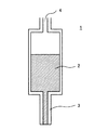
エレクトロニクス分野で、ボンディング(接着)用等のペーストを、例えばリードフレーム上に供給する方法としては、図1に示すように、液状流動体溜め2と、当該液状流動体溜め2に連結されたノズル3とよりなる吐出装置1を主要構成要素とするディスペンサが知られている。
【0003】
図1の吐出装置では、液状流動体溜め2内のペーストが、加圧気体供給口4から供給される加圧気体の力により、ノズル3の先端から押し出される方式が多い。
【0004】
通常ディスペンサは、内部が空洞になっている円筒状のニードルノズルが多く用いられ、先端からの吐出を、液状流動体溜めであるシリンジ内部に付加させた圧力の増減や加圧時間設定にてコントロールしている。
【0005】
銀フィラー入りペースト等をディスペンサにて定量塗布する場合、一般的に使用されているニードルノズルを用いると、ニードルノズル内部の液詰まりが発生するために起こる空うちや、脱泡が不十分なため気泡が残存し、ペーストが加圧された場合にその気泡の収縮が加圧分を吸収してしまうことによる空うちを発生する場合がある。
【0006】
また、流動性が悪くコントロールの困難なペーストに対して、精密ノズルと言われるノズル内部に円錐状のテーパをつけたタイプが製品化されているが、若干の流動性の向上は見られるものの従来のニードルノズルの20倍以上と高価である上、塗布対象物との間に高い位置精度が必要であり、完全に不具合を解消するには至っていない。
【0007】
また、高粘度ぺーストに対して、シリンジとノズルとの中間にスクリュー等を組み込み、液状流動体を強制的に吐出するタイプも製品化されているが、こちらも高価である上、メンテナンスを必要とする。
【0008】
さらに、実公昭59−36306号公報には、図2に示す如く、液状流動体溜め6とノズル7とノズル内に挿入されたノズル先端の内径よりやや小さい芯線8とこの芯線8をノズル7内で上下動可動にするためのバネ9とよりなる吐出装置5が開示されている。
【0009】
この装置では、液状流動体は加圧によってノズル外に吐出されるのではなく、次のようなサイクルの動作により吐出される。
【0010】
▲1▼ ノズル内にある芯線8の一部がバネ9の作用でノズル外に移動することにより液状流動体が取り出される。
【0011】
▲2▼ ノズル7が液状流動体の被着体(本願明細書では、このように液状流動体を付着させる目的物を被着体と称する)に押しつけられる際に、ノズル先端と芯線8との間の液状流動体がかき落とされて被着体上に平坦な形状を形成する。
【0012】
▲3▼ 次いで、ノズル7が液状流動体の被着体から遠ざかると被着体上の液状流動体は、平坦な形状を保って被着体上に残る。
【0013】
▲4▼ 一方、バネ9の作用で、ノズル内にある芯線8の一部が再びノズル外に移動することにより液状流動体が取り出される。つまり、上記▲1▼の段階が繰り返される。
【0014】
この発明は、被着体上に残された液状流動体が半球状にならず、平坦になり、従ってボンディング時にチップ等を正常な位置関係に固定できることを目的としたものである。
【0015】
ただし、この発明は、空うちの防止については何も示唆していない。
【0016】
また、この装置はバネ等の構造が複雑であるため、加圧気体の導入経路を造る等、液状流動体を吐出するための他の手段を併設することが困難である。
【0017】
さらに、上記公報では、「ノズル先端の内径よりやや小さい芯線」という表現で表しているように、上記▲2▼の工程での掻き取りを行うためにはノズル先端と芯線8との間の隙間の大きさを狭くすることが必須となる。
【0018】
また、液状流動体の吐出量は、この隙間と、液状流動体の粘度、チキソトロピー性、および上記サイクルの速度等に大きく影響されるところ、液状流動体の粘度、チキソトロピー性は液状流動体の品質のバラツキ、液状流動体の温度等によって変動し、一定範囲の生産速度(すなわち上記サイクルを一定にすること)を保ちつつ、一定の液状流動体吐出量を維持するためには、芯線8の大きさやノズルの大きさを微妙に変更する頻度が高いという問題がある。
【0019】
【発明が解決しようとする課題】
本願発明の目的の一つは、構造の簡単な液状流動体吐出装置により、空うちがなく、あるいは少なく、生産性が高く、または、液状流動体の吐出量の変更、調整が容易にできる液状流動体吐出技術を提供することである。
【0020】
本願発明のさらに他の目的および利点は、以下の説明から明らかになるであろう。
【0021】
【課題を解決するための手段】
すなわち、本願発明の1態様は、
液状流動体を吐出するためのノズルと、
当該ノズルに挿入して使用される糸状体と、
を含む液状流動体の吐出装置であって、当該糸状体が
当該糸状体の先端に圧力が加えられていないときには当該ノズルの外に露出している先端部分AAと、
当該ノズル内に挿入できる部分BBと、
当該糸状体に関し、当該先端部分AAとは反対側にあり部分BBから折り曲げられた部分CCと、
を有する吐出装置
である。
【0022】
また、本願発明の他の1態様は、
このような吐出装置を使用し、
前記液状流動体の被着体と非接触の状態にある前記糸状体の先端を当該被着体に圧着し、かつ当該ノズルを当該被着体に近接させることにより、先端部分AAを前記ノズル外から内に移動させつつ、当該液状流動体を当該被着体上に移動させる段階と、
当該糸状体の先端の当該被着体への圧着を緩和し、かつ当該ノズルを当該被着体から遠ざかる方向に移動して、当該被着体上に所定量の液状流動体を残留せしめ、同時に、部分CCの折れ曲がりにより、先端部分AAを、前記ノズル内から外に移動させ、その際に液状流動体を当該ノズル外に移動させる段階と
を有することを特徴とする液状流動体の吐出方法
である。
【0023】
折れ曲がりという簡単な構造により糸状体をノズル内で移動させることにより、液状流動体のスムーズな取り出しが可能になる。
【0024】
これは生産性の向上につながり、また前記空うちの防止にもなる。
【0025】
また、折れ曲がりという簡単な構造を採用するため、吐出に際して、液状流動体を吐出するための加圧装置を併用することが可能となり、生産目的に応じて液状流動体の吐出量の変更をすることが容易になる。
【0026】
さらに、液状流動体を吐出するための加圧装置を併用すると、吐出量の変動を防止でき、あるいはその調整が容易になる。
【0027】
なお、以下に説明する発明の実施の形態や図面の中で、本願発明の更なる特徴が明らかにされる。
【0028】
【発明の実施の形態】
以下に、本願発明の実施の形態を図や実施例を使用して説明する。なお、これらの図や実施例および説明は本願発明を例示するものであり、本願発明の範囲を制限するものではない。本願発明の趣旨に合致する限り他の実施の形態も本願発明の範疇に属し得ることは言うまでもない。なお、同一の部分については同一の符号を付す場合がある。
【0029】
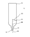
図3は、本願発明に係る吐出装置11を示す図である。
【0030】
図3において、糸状体14は、ノズル13の内部を通り、液状流動体溜め12に達している。
【0031】
この糸状体14は一部が先端部分AA(点線)に示すようにノズル13の外にあり、他端側が、部分CC(点線)に示すように折れ曲がっている。
【0032】
この折れ曲がりはバネ作用を有するため、糸状体14の先端を何かに押しつけると、図3中の糸状体14の実線部分で示すように変形することにより、先端部分AAがノズル13の内部に移動するが、押しつけるのを止めると、先端部分AAと部分CCとが点線で示すような位置に移動し、先端部分AAは再びノズル13の外に出る。
【0033】
この動作を更に図4を用いて説明する。
【0034】
図4A〜4Eはこの動作の段階を示すものである。符号は主に図4Aに付し、図4B〜4Eでは、同一の箇所については省略してある場合がある。
【0035】
動作は以下の通りである。
【0036】
(1)図4Aに示すようにノズル13に挿入された糸状体14の先端部分AAの回りに液状流動体15が付着している状態から出発する。この状態では糸状体14は被着体16と非接触の状態にある。そこで、ノズル13をXの方向、すなわち被着体16の方向に移動させる。
【0037】
(2)図4Bは、糸状体14の先端が被着体16に接触した後更にノズル13がXの方向に移動する途中経過を示すものである。液状流動体はノズル外に出ると若干膨らむ傾向を有し、また、多くの場合チキソトロピー性を有するため、非流動状態では増粘し、糸状体14から掻き落され、図中下方にずり落ちていく。
【0038】
なお、糸状体14の先端が被着体16に接触した後は、折れ曲がりのバネ作用により、図3中の糸状体14の部分CCが実線部分で示すように変形し、先端部分AAがノズル13の内部に移動する。
【0039】
この際、糸状体14が被着体16に圧着され、液状流動体が被着体16に付着して行くが、一部はノズル13と糸状体14との間を通って液状流動体溜め12の方向に逆流する。
【0040】
この逆流は、ノズル13と糸状体14との間の相対的運動により、液状流動体が流動し、チキソトロピー性を有する場合には減粘することによって促進されているようである。
【0041】
そして、検討の結果、この逆流が、液状流動体の吐出量の変動に対し、バッファの役割を果たし、液状流動体の吐出量のバラツキを減少させていることが判明した。
【0042】
なお、ノズル13と糸状体14との間の相対的運動の速度、ノズル13と糸状体14との間の距離や断面積等種々の因子により、この逆流量を調整することが可能である。
【0043】
(3)ついで、図4Cに示すように、糸状体14が被着体16に圧着され、ノズル13の先端を被着体16に近接させると、被着体16上にある液状流動体15が例えば平坦になるように押しつぶされる。
【0044】
なお、本願発明において、「ノズルを当該被着体に近接させる」とは、このように液状流動体が押しつぶされるまで接近させることをいう。
【0045】
(4)ついで、図4Dに示すように、糸状体14の先端の当該被着体16への圧着を緩和し、かつノズル13をX’方向、つまり被着体16から遠ざかる方向に移動して、被着体16上に所定量の液状流動体を転写して、残留液状流動体17として残留せしめる。この糸状体14の先端の当該被着体16への圧着の緩和に従い、先端部分AAは再びノズル13の外に出てくる。そしてこの動作に伴い、液状流動体15が先端部分AAに付着した状態でノズル13の外に出てくる。
【0046】
(5)そして、図4Eに示すように、先端部分AAが残留液状流動体17と離れていき、図4Aの状態に復帰する。
【0047】
このような動作を実現するための、バネ構造としては、上記のように折れ曲がりを有すれば充分であることが判明した。
【0048】
この場合、糸状体14を固定する手段としては、図3に示すように、液状流動体溜め12に部分CCを保持するためのくぼみ18等を設けることも有用である。
【0049】
また、図5Aに示すように、部分CCにコイルバネ状の構造を付与し、液状流動体溜め12に図5B,Cに、示すようなくぼみ19等を設けることも有用である。
【0050】
上記のいずれの場合にも、糸状体14はノズル13とは反対側から液状流動体溜め12内に挿入することが考えられる。
【0051】
図5A,B,Cに示す方法はくぼみの作製が比較的容易であり、かつ、その保持の信頼性が高いので、より好ましいと言える。
【0052】
このような吐出装置の寸法を例示すれば、断面が10mm〜30mmの円形である、容積が5〜50mLの液状流動体溜め12、内径の断面が0.3mm〜1.2mmの円形であるノズル13、径の断面が0.1mm〜0.8mmの円形である中実の糸状体14が考えられる。
【0053】
液状流動体溜め12、ノズル13、糸状体14の材料としては、金属、プラスチック、セラミックス類、それらの複合体を含む公知のどのようなものでも、本願発明の趣旨に合致すれば使用可能である。
【0054】
なお、糸状体は、液状流動体をその回りに付着せしめ、液状流動体に対し実質的に不活性であり、ノズル内で移動する際に実質的に屈曲することがないものであればどのようなものでも良い。
【0055】
ただし、糸状体、更に厳密に言えば少なくとも糸状体の部分CCについては、バネの作用を発揮するため、弾性体からなっていることが好ましい。
【0056】
また、糸状体自体は、上記の部分AA,BB,CCが同一の材質からなる一体物であることが、工作性、信頼性の上から好ましい。
【0057】
弾性体としては、金属、プラスチック等種々のものが考えられるが、ある程度の応力に抗するものであることが必要であり、グラスファイバ、カーボンファイバ、鋼線を好ましいものとして例示できる。
【0058】
上記部分AAについては、例えば図6A,Bに例示するように、先細になっていることが好ましい。先端部分AAが残留液状流動体17と離れて行くときに液状流動体の液切れがスムーズに行き、残留液状流動体17の形状や残留量の変動が少なくなるからである。
【0059】
また、少なくとも部分AAと、部分BBが前記液状流動体に接触する部位との少なくともいずれかについて、その表面が粗面、凹部、凸部、凹凸部、筋状の凹部、凸部、凹凸部の少なくともいずれかを有していることが好ましい。糸状体14が、ノズル内からノズル外へと移動する際に、その表面に付着した液状流動体がノズル外へ取り出されやすくなるからである。
【0060】
特に、図6Cに示すように、糸状体14がノズル内からノズル外へと移動する際には、剪断応力が大きく働き、その表面に付着した液状流動体がノズル外へ押し出されやすくなる一方、逆方向にはそれほど押し出されやすくならないことが、液状流動体の吐出の向上に寄与し得る。
【0061】
しかしながら、そのような構造を持たなくても、上記粗面、凹部、凸部、凹凸部、筋状の凹部、凸部、凹凸部があると、糸状体14の表面に付着した液状流動体がノズル外へ取り出されやすくなる。これは、液状流動体がある程度の粘度を有しており、またチキソトロピー性を持つことが多いためと推定される。粗面や凹部、凸部、凹凸部の適切な深さ高さは、糸状体を試作しテストすることで容易に見出すことができる。
【0062】
なお、上記のような実施形態では、ノズル13と糸状体14とは、断面の円を同心円状に配置するのが普通であるが、必ずしも同心円状である必要はない。
【0063】
また、ノズル13の内壁面と糸状体14とが接触することも問題とならない場合が多い。
【0064】
具体的にいえば、糸状体14の先端を被着体16に押しつけるときに特に大きな力が要求されなければ、操作上の問題はなく、液状流動体の吐出量のバラツキも問題にならない場合が多い。
【0065】
本願発明のように折れまがり構造を利用する場合、最初はノズル13の内壁面と糸状体14とが接触せず、糸状体14の先端が被着体16に押しつけられると、ノズル13の内壁面と糸状体14とが接触するようになる場合もあるが、これも問題とならない場合が多い。
【0066】
なお、ノズル13と糸状体14とが、断面の円を同心円状態上に配置するような普通の場合を考えると、部分CCの折り曲げられた角度が、90±10゜の間にあることが望ましい。
【0067】
このような値を選択することにより、糸状体14の先端を被着体16に押しつけるときに過大な力を要せず、糸状体にも過大な曲げ応力が掛からず、長期間に渡って信頼性を保てると考えられる。
【0068】
ノズル13の内径と糸状体14の断面との関係は、糸状体の内、少なくとも部分BBが前記液状流動体に接触する部位であって先細でない箇所および前記ノズルについて、ノズルの方向と直交する断面(それぞれ断面積断面積SBおよび断面積SN)が0.3≦SB/SN≦0.7の関係を有することが好ましい。0.7<SB/SNであると、液状流動体の吐出の際に液状流動体に掛かる剪断応力が大きく、糸状体14がノズル13の外から内に戻るのに時間が掛かりすぎ、SB/SN<0.3であると、液状流動体に掛かる剪断応力が小さく、吐出量がばらつく場合が生じやすいからである。
【0069】
なお、液状流動体のスムーズな取り出しのためには、糸状体と液状流動体とはある程度の親和性を有していることが好ましい。
【0070】
液状流動体については、本願発明は、その粘度が10Pa・s〜100Pa・sの間にある場合に特に好適に適用できる。粘度が高すぎると液状流動体の吐出量の確保が困難になり、粘度が低すぎると液状流動体の吐出量が変動する可能性が出てくるからである。
【0071】
ここで、本願発明において、「液状流動体」には、通常の液体の他、ゾル状態にあるもの、液体中に固体、他の液体等を分散させたペースト、懸濁物、乳濁物が含まれる。
【0072】
なお、上記においては、糸状体の動きのみで液状流動体が吐出されるが、本願発明では、その構造が簡単であることから、吐出装置に、ノズルを介して液状流動体を吐出するための加圧装置を有するようにすることもできる。
【0073】
そして、この場合には、より高い吐出量制御、吐出量のより小さいバラツキという効果と共に、上述した空うちの減少,防止といった効果も実現することがより容易となる。
【0074】
特に、加圧装置を併用すれば、糸状体の機能を、その動きによって、液状流動体に流動性を与えることにより、部分的な液状流動体の閉塞、増粘を防止することに主に利用し、加圧装置の機能を、液状流動体の吐出に利用することができるため、ノズルと糸状体との隙間の大きさに対する煩わされることなく、より高い吐出量制御、吐出量のより小さいバラツキの吐出装置を得ることが容易になる。
【0075】
本願発明は、半導体チップ等の電子デバイスをリードフレーム上や基板上に接着する場合、電子部品同士等の接合の場合、潤滑剤、シール剤の塗布の場合等に適用することが可能である。
【0076】
また、その際の液状流動体としては、銀ペースト等の導電ペースト、抵抗ペースト、絶縁ペースト、エポキシ剤、グリース、封止剤等を例示することができる。
【0077】
以下に本願発明の1実施例を示す。
【0078】
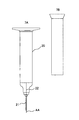
図7のようにして液状流動体吐出装置を組み立てた。
【0079】
先ず、図7Aのようなノズルの付いた液状流動体溜め20を用意した。この液状流動体溜め20は、プラスチック製であり、その円断面直径は12.6mm、容積は5mLであった。
【0080】
この液状流動体溜め20は、図5Bのようなくぼみ(図示せず)を有していた。
【0081】
ノズル21はステンレススチール製で、断面が円形で、外径が0.81mm、内径が0.51mmであった。
【0082】
別途、図5Aに示すような、部分CCがコイルバネ状の構造を有し、部分CCが部分BBから90゜に折り曲げられている、断面が円形で直径が0.2mmの鋼線からなる糸状体22を準備した。
【0083】
この糸状体22は図7Aの紙面上方から図7Bの挿入工具を使用して液状流動体溜め内に挿入され、上記くぼみにて保持された。
【0084】
この状態で、糸状体22の先端部分AAに該当する部分の長さは1.5mmであった。
【0085】
なお、この先端部分は図6Aのように30゜の角度を有する円錐形状に先細になっていた。
【0086】
このような液状流動体吐出装置を使用し、液状流動体溜めの上部から、図示しない加圧装置を介して必要に応じて1520hPaの空気圧(絶対圧表示)を掛けつつ、120サイクル/分の速度で粘度が45Pa・s(E型粘度計で測定)の銀ペーストを、4mg/回の割合で吐出した。加圧装置としては公知のどのようなものでも使用できる。
【0087】
この装置で、圧電チップを基板に接着する作業を行った結果、10万回のサイクルで、空うち、20%以上の吐出量不足等のミスショットゼロを確認できた。
【0088】
なお、本願発明では、上記に説明したように、液状流動体の吐出量の調整が容易になることから、ノズルと被着体との相互距離について、従来のような厳しい管理が不要になる利点も生じる。
【0089】
すなわち、従来法では、ノズルを被着体にどれだけ近づけるかによって、吐出量を管理することが多く、接近させすぎるとノズルや被着体の損傷を引き起こし、逆に離れ過ぎると塗布ミス(吐出量不足)の原因になっていたが、本願発明に掛かる技術では、糸状体の材質、形状、加圧気体との併用等により、容易に吐出量の調整ができ、上記の問題を軽減することが可能となる。
【0090】
特に、先述した如く、加圧装置を併用すれば、より高い吐出量制御、吐出量のより小さいバラツキの吐出装置を得ることが容易になり、従って吐出量の調整もより容易になる。
【0091】
本願発明は、半導体チップ等の電子デバイスをリードフレームや基板上に接着する場合、電子部品同士等の接合、潤滑剤、シール剤の塗布の場合等に特に有用である。また、1〜20mg/回のショットで10〜180サイクル/分の能力を要する用途に特に適する。
【0092】
【発明の効果】
本願発明の態様に依存して、空うちのない、あるいは空うちの少ない液状流動体吐出技術を提供できる。
【0093】
さらに、本願発明の態様に依存して、構造の簡単な液状流動体吐出装置を提供できる。
【0094】
さらに、本願発明の態様に依存して、生産性の高い、すなわち吐出サイクル時間を小さくできる液状流動体吐出技術を提供できる。
【0095】
さらに、本願発明の態様に依存して、液状流動体の吐出量の変更、調整が容易にできる液状流動体吐出技術を提供できる。
【図面の簡単な説明】
【図1】液状流動体溜めと、当該液状流動体溜めに連結されたノズルとよりなる吐出装置を示す図である。
【図2】液状流動体溜めとノズルとノズル内に挿入された芯線とバネとよりなる公知の吐出装置を示す図である。
【図3】本願発明に係る吐出装置の1例を示す図である。
【図4】本願発明に係る吐出装置の動作を示す図である。図4A〜4Eはこの動作の諸段階を示すものである。
【図5】本願発明に係る部分CCにコイルバネ状の構造を有する糸状体の1例とその取り付けのための凹みとを例示する図である。図5Aは、部分CCにコイルバネ状の構造を有する糸状体を示し、図5B,Cは、そのようなくぼみを示す。
【図6】糸状体の横断面構造を示す図である。図6Aは円錐状の先細構造を示し、図6Bは円柱を斜めに切った先細構造を示す。図6Cは、図中下方から上方に向かい円錐台が重畳した構造を示す図である。
【図7】本願発明に係る液状流動体吐出装置の組み立て方法を示す図である。図7Aは糸状体とノズルの付いた液状流動体溜めを示す。図7Bは糸状体の挿入工具を示す。
【符号の説明】
1,5,11 吐出装置
2,6,12,20 液状流動体溜め
3,7,13,21 ノズル
4 加圧気体供給口
8 芯線
9 バネ
14,22 糸状体
15 液状流動体
16 被着体
17 残留液状流動体
18,19 くぼみ[0001]
BACKGROUND OF THE INVENTION
The present invention relates to a liquid fluid discharge device and discharge method. In particular, the present invention relates to a dense liquid fluid ejecting apparatus and ejecting method in a paste dispenser in the case of applying a paste typified by an adhesive paste for adhering a semiconductor chip to a lead frame.
[0002]
[Prior art]
In the electronics field, as a method for supplying a bonding paste or the like onto a lead frame, for example, as shown in FIG. 1, a
[0003]
In the discharge device of FIG. 1, there are many methods in which the paste in the
[0004]
The dispenser usually uses a cylindrical needle nozzle with a hollow inside, and the discharge from the tip is controlled by increasing or decreasing the pressure applied to the inside of the syringe that is a liquid fluid reservoir and setting the pressurization time. is doing.
[0005]
When applying a fixed amount of paste containing silver filler with a dispenser, if a commonly used needle nozzle is used, the air inside the needle nozzle may become clogged and the degassing will be insufficient. When bubbles remain and the paste is pressurized, the shrinkage of the bubbles may generate voids due to absorption of the pressurized portion.
[0006]
In addition, for pastes with poor fluidity and difficult to control, a type with a conical taper inside the nozzle, which is called a precision nozzle, has been commercialized. In addition to being 20 times more expensive than the needle nozzle, high positional accuracy is required between the needle nozzle and the object to be coated, and the problem has not been completely solved.
[0007]
In addition, for high-viscosity pastes, a type in which a screw or the like is incorporated between the syringe and nozzle to forcibly discharge the liquid fluid has been commercialized, but this is also expensive and requires maintenance And
[0008]
Furthermore, in Japanese Utility Model Publication No. 59-36306, as shown in FIG. 2, a liquid fluid reservoir 6, a nozzle 7, a core wire 8 slightly smaller than the inner diameter of the nozzle tip inserted into the nozzle, and the core wire 8 are placed in the nozzle 7. A discharge device 5 comprising a spring 9 for moving up and down is disclosed.
[0009]
In this apparatus, the liquid fluid is not discharged outside the nozzle by pressurization, but is discharged by the following cycle operation.
[0010]
(1) A part of the core wire 8 in the nozzle moves out of the nozzle by the action of the spring 9, whereby the liquid fluid is taken out.
[0011]
(2) When the nozzle 7 is pressed against the adherend of the liquid fluid (in this specification, the object to which the liquid fluid adheres is referred to as the adherend), the nozzle tip and the core wire 8 The liquid fluid in between is scraped off to form a flat shape on the adherend.
[0012]
(3) Next, when the nozzle 7 moves away from the adherend of the liquid fluid, the liquid fluid on the adherend remains on the adherend while maintaining a flat shape.
[0013]
(4) On the other hand, by the action of the spring 9, a part of the core wire 8 in the nozzle moves again to the outside of the nozzle, whereby the liquid fluid is taken out. That is, step (1) is repeated.
[0014]
An object of the present invention is that the liquid fluid left on the adherend does not become hemispherical and is flattened, so that the chip or the like can be fixed in a normal positional relationship during bonding.
[0015]
However, this invention does not suggest anything about the prevention of airspace.
[0016]
In addition, since this apparatus has a complicated structure such as a spring, it is difficult to provide other means for discharging the liquid fluid, such as creating an introduction path for pressurized gas.
[0017]
Further, in the above publication, as indicated by the expression “core wire slightly smaller than the inner diameter of the nozzle tip”, the gap between the nozzle tip and the core wire 8 is used for scraping in the step (2). It is essential to reduce the size of.
[0018]
In addition, the discharge amount of the liquid fluid is greatly affected by the gap, the viscosity of the liquid fluid, the thixotropy, the speed of the above cycle, etc. The viscosity and thixotropy of the liquid fluid are the quality of the liquid fluid. In order to maintain a constant liquid fluid discharge amount while maintaining a certain range of production speed (that is, making the above cycle constant), the core wire 8 is large. There is a problem in that the frequency of changing the size of the sheath or nozzle is high.
[0019]
[Problems to be solved by the invention]
One of the objects of the present invention is a liquid fluid discharge device having a simple structure, which has a small or small space, high productivity, or a liquid that can easily change or adjust the discharge amount of the liquid fluid. It is to provide fluid discharge technology.
[0020]
Other objects and advantages of the present invention will become apparent from the following description.
[0021]
[Means for Solving the Problems]
That is, one aspect of the present invention is
A nozzle for discharging a liquid fluid;
A filament that is inserted into the nozzle and used;
A liquid fluid discharge device comprising: a tip portion AA that is exposed to the outside of the nozzle when no pressure is applied to the tip of the filament.
A portion BB that can be inserted into the nozzle;
With respect to the filamentous body, a portion CC on the side opposite to the tip portion AA and bent from the portion BB;
It is the discharge device which has.
[0022]
Another aspect of the present invention is as follows:
Using such a discharge device,
The tip of the filamentous body that is not in contact with the adherend of the liquid fluid is pressure-bonded to the adherend, and the nozzle is brought close to the adherend, so that the tip portion AA is moved outside the nozzle. Moving the liquid fluid onto the adherend while moving it from the inside,
Relieve pressure bonding of the tip of the filamentous body to the adherend, and move the nozzle away from the adherend to leave a predetermined amount of liquid fluid on the adherend, and at the same time And a step of moving the tip portion AA from the inside of the nozzle by bending the portion CC, and moving the liquid fluid to the outside of the nozzle at that time. is there.
[0023]
By moving the filamentous body within the nozzle with a simple structure of bending, the liquid fluid can be taken out smoothly.
[0024]
This leads to an improvement in productivity and also prevents the air space.
[0025]
In addition, since a simple structure of bending is adopted, it becomes possible to use a pressurizing device for discharging the liquid fluid at the time of discharging, and the discharge amount of the liquid fluid can be changed according to the production purpose. Becomes easier.
[0026]
Furthermore, when a pressurizing device for discharging the liquid fluid is used in combination, fluctuations in the discharge amount can be prevented or adjustment thereof becomes easy.
[0027]
Further features of the present invention will be made clear in the embodiments and drawings of the invention described below.
[0028]
DETAILED DESCRIPTION OF THE INVENTION
Embodiments of the present invention will be described below with reference to the drawings and examples. In addition, these figures, examples, and explanations illustrate the present invention, and do not limit the scope of the present invention. It goes without saying that other embodiments may belong to the category of the present invention as long as they match the gist of the present invention. In addition, about the same part, the same code | symbol may be attached | subjected.
[0029]
FIG. 3 is a view showing the
[0030]
In FIG. 3, the
[0031]
A part of the
[0032]
Since this bend has a spring action, when the tip of the
[0033]
This operation will be further described with reference to FIG.
[0034]
4A-4E show the stages of this operation. The reference numerals are mainly attached to FIG. 4A, and in FIGS. 4B to 4E, the same portions may be omitted.
[0035]
The operation is as follows.
[0036]
(1) As shown in FIG. 4A, the process starts from a state in which the
[0037]
(2) FIG. 4B shows a process in which the
[0038]
After the tip of the
[0039]
At this time, the
[0040]
This reverse flow seems to be promoted by the thinning of the liquid fluid due to the relative movement between the
[0041]
As a result of the examination, it has been found that the backflow plays a role of a buffer with respect to fluctuations in the discharge amount of the liquid fluid and reduces variations in the discharge amount of the liquid fluid.
[0042]
The reverse flow rate can be adjusted according to various factors such as the speed of the relative movement between the
[0043]
(3) Next, as shown in FIG. 4C, when the
[0044]
In the present invention, “to bring the nozzle close to the adherend” refers to making the liquid fluid approach until it is crushed in this way.
[0045]
(4) Next, as shown in FIG. 4D, the pressure bonding of the tip of the
[0046]
(5) And as shown to FIG. 4E, the front-end | tip part AA leaves | separates from the
[0047]
It has been found that it is sufficient for the spring structure to realize such an operation to have a bend as described above.
[0048]
In this case, as a means for fixing the
[0049]
Further, as shown in FIG. 5A, it is also useful to give a coil spring-like structure to the portion CC and to provide the
[0050]
In any of the above cases, it is conceivable that the
[0051]
The method shown in FIGS. 5A, 5B, and 5C is more preferable because the recess is relatively easy to manufacture and its holding reliability is high.
[0052]
As an example of the dimensions of such a discharge device, a nozzle having a circular shape with a cross section of 10 to 30 mm, a
[0053]
As the material for the
[0054]
Any filamentous material can be used as long as it adheres the liquid fluid around it, is substantially inert to the liquid fluid, and does not substantially bend when moving in the nozzle. It can be anything.
[0055]
However, the filamentous body, more strictly speaking, at least the portion CC of the filamentous body is preferably made of an elastic body in order to exert the action of a spring.
[0056]
Further, it is preferable from the viewpoint of workability and reliability that the filamentous body itself is an integral body in which the above-described portions AA, BB, and CC are made of the same material.
[0057]
Various materials such as metal and plastic can be considered as the elastic body, but it is necessary to resist a certain amount of stress, and glass fiber, carbon fiber, and steel wire can be exemplified as preferable examples.
[0058]
The portion AA is preferably tapered as exemplified in FIGS. 6A and 6B, for example. This is because when the tip portion AA moves away from the
[0059]
The surface of at least one of the part AA and the part where the part BB is in contact with the liquid fluid is rough surface, concave part, convex part, concave and convex part, streaky concave part, convex part and concave and convex part. It is preferable to have at least one of them. This is because when the
[0060]
In particular, as shown in FIG. 6C, when the
[0061]
However, even if it does not have such a structure, if there are the rough surface, concave portion, convex portion, concave and convex portion, streak concave portion, convex portion, and concave and convex portion, the liquid fluid attached to the surface of the
[0062]
In the embodiment as described above, the
[0063]
In many cases, the contact between the inner wall surface of the
[0064]
Specifically, if a particularly large force is not required when pressing the tip of the
[0065]
When a folded structure is used as in the present invention, the inner wall surface of the
[0066]
In addition, considering the normal case where the
[0067]
By selecting such a value, an excessive force is not required when the tip of the
[0068]
The relationship between the inner diameter of the
[0069]
For smooth removal of the liquid fluid, it is preferable that the filament and the liquid fluid have a certain degree of affinity.
[0070]
As for the liquid fluid, the present invention can be particularly suitably applied when the viscosity is between 10 Pa · s and 100 Pa · s. This is because if the viscosity is too high, it is difficult to ensure the discharge amount of the liquid fluid, and if the viscosity is too low, the discharge amount of the liquid fluid may fluctuate.
[0071]
Here, in the present invention, the “liquid fluid” includes not only ordinary liquids but also those in a sol state, pastes, suspensions, and emulsions in which solids, other liquids, etc. are dispersed in liquids. included.
[0072]
In the above, the liquid fluid is discharged only by the movement of the filamentous body, but in the present invention, since the structure is simple, the liquid fluid is discharged to the discharge device via the nozzle. It can also have a pressurizing device.
[0073]
In this case, it becomes easier to realize the above-described effects of reducing and preventing the void, as well as the effects of higher discharge amount control and smaller discharge amount variations.
[0074]
In particular, if a pressure device is used in combination, the function of the filamentous body is mainly used to prevent partial clogging and thickening of the liquid fluid by imparting fluidity to the liquid fluid by its movement. In addition, since the function of the pressurizing device can be used for the discharge of the liquid fluid, there is no need to bother with the size of the gap between the nozzle and the filamentous body, so that a higher discharge amount control and a smaller discharge amount variation. It becomes easy to obtain the discharge device.
[0075]
The present invention can be applied to bonding an electronic device such as a semiconductor chip on a lead frame or a substrate, bonding electronic components or the like, or applying a lubricant or a sealant.
[0076]
Moreover, as a liquid fluid in that case, conductive pastes, such as a silver paste, resistance paste, insulating paste, an epoxy agent, grease, a sealing agent, etc. can be illustrated.
[0077]
One embodiment of the present invention is shown below.
[0078]
The liquid fluid discharge device was assembled as shown in FIG.
[0079]
First, a
[0080]
The
[0081]
The
[0082]
Separately, as shown in FIG. 5A, the part CC has a coil spring-like structure, the part CC is bent at 90 ° from the part BB, and a thread-like body made of a steel wire having a circular cross section and a diameter of 0.2 mm. 22 were prepared.
[0083]
The
[0084]
In this state, the length of the portion corresponding to the tip portion AA of the
[0085]
Note that the tip portion was tapered in a conical shape having an angle of 30 ° as shown in FIG. 6A.
[0086]
Using such a liquid fluid discharge device, the air pressure of 1520 hPa (absolute pressure display) is applied from the upper part of the liquid fluid reservoir via a pressure device (not shown) as necessary, and the speed is 120 cycles / minute. The silver paste having a viscosity of 45 Pa · s (measured with an E-type viscometer) was discharged at a rate of 4 mg / time. Any known pressurizing device can be used.
[0087]
As a result of performing the operation of bonding the piezoelectric chip to the substrate with this apparatus, it was possible to confirm zero miss shots such as insufficient discharge amount of 20% or more in the air in 100,000 cycles.
[0088]
In the invention of the present application, as described above, the adjustment of the discharge amount of the liquid fluid is facilitated, so that the conventional strict management is not required for the mutual distance between the nozzle and the adherend. Also occurs.
[0089]
That is, in the conventional method, the discharge amount is often managed depending on how close the nozzle is to the adherend. If the nozzle is too close, the nozzle or the adherend is damaged. However, with the technology according to the present invention, the discharge amount can be easily adjusted by using the material, shape, and pressurized gas of the filamentous material, and the above problems can be reduced. Is possible.
[0090]
In particular, as described above, when the pressurizing device is used in combination, it becomes easy to obtain a discharge device with higher discharge amount control and smaller discharge amount variation, and therefore, the discharge amount can be easily adjusted.
[0091]
The present invention is particularly useful for bonding an electronic device such as a semiconductor chip onto a lead frame or a substrate, joining electronic components, etc., applying a lubricant, or a sealant. In addition, it is particularly suitable for applications that require the ability of 10 to 180 cycles / minute with 1 to 20 mg / shot.
[0092]
【The invention's effect】
Depending on the aspect of the present invention, it is possible to provide a liquid fluid discharge technique that has no air or little air.
[0093]
Furthermore, depending on the aspect of the present invention, a liquid fluid discharge device having a simple structure can be provided.
[0094]
Furthermore, depending on the aspect of the present invention, it is possible to provide a liquid fluid discharge technique with high productivity, that is, a discharge cycle time can be reduced.
[0095]
Furthermore, depending on the aspect of the present invention, it is possible to provide a liquid fluid discharge technique capable of easily changing and adjusting the discharge amount of the liquid fluid.
[Brief description of the drawings]
FIG. 1 is a view showing a discharge device including a liquid fluid reservoir and a nozzle connected to the liquid fluid reservoir.
FIG. 2 is a view showing a known discharge device including a liquid fluid reservoir, a nozzle, a core wire inserted into the nozzle, and a spring.
FIG. 3 is a view showing an example of a discharge device according to the present invention.
FIG. 4 is a view showing the operation of the ejection device according to the present invention. 4A-4E show the stages of this operation.
FIG. 5 is a diagram illustrating an example of a thread-like body having a coil spring-like structure in a portion CC according to the present invention and a dent for attaching the same. FIG. 5A shows a thread-like body having a coil spring-like structure in the portion CC, and FIGS. 5B and 5C show such depressions.
FIG. 6 is a diagram showing a cross-sectional structure of a filamentous body. FIG. 6A shows a conical tapered structure, and FIG. 6B shows a tapered structure in which a cylinder is cut obliquely. FIG. 6C is a diagram showing a structure in which a truncated cone is superimposed from the lower side to the upper side in the drawing.
FIG. 7 is a view showing an assembling method of the liquid fluid discharge device according to the present invention. FIG. 7A shows a liquid fluid reservoir with thread and nozzle. FIG. 7B shows a thread insertion tool.
[Explanation of symbols]
1, 5, 11
Claims (10)
当該ノズルに挿入して使用される糸状体と、
を含む液状流動体の吐出装置であって、当該糸状体が、
当該糸状体の先端に圧力が加えられていないときには当該ノズルの外に露出しており、当該糸状体の先端に圧力が加えられているときには当該ノズルの内部に向けて移動可能である先端部分AAと、
当該ノズル内に挿入できる部分BBと、
当該糸状体に関し、当該先端部分AAとは反対側にあり部分BBから折り曲げられた部分CCと、
を有し、
当該先端部分AAの移動により当該液状流動体を吐出させる吐出装置。A nozzle for discharging a liquid fluid;
A filament that is inserted into the nozzle and used;
A liquid fluid discharge device comprising :
A tip portion AA that is exposed outside the nozzle when no pressure is applied to the tip of the filamentous body, and is movable toward the inside of the nozzle when pressure is applied to the tip of the filamentous body. and,
A portion BB which can be inserted into those the nozzle,
It relates those filamentous body, a portion CC bent from the portion BB is opposite from that of the tip portion AA,
I have a,
Ejection detection device for discharging the liquid fluid by movement of the tip portion AA.
Priority Applications (3)
| Application Number | Priority Date | Filing Date | Title |
|---|---|---|---|
| JP2001344083A JP3894776B2 (en) | 2001-11-09 | 2001-11-09 | Discharge device and discharge method |
| US10/267,667 US6960258B2 (en) | 2001-11-09 | 2002-10-10 | Discharge device and discharge method |
| US11/199,131 US7784653B2 (en) | 2001-11-09 | 2005-08-09 | Discharge device and discharge method |
Applications Claiming Priority (1)
| Application Number | Priority Date | Filing Date | Title |
|---|---|---|---|
| JP2001344083A JP3894776B2 (en) | 2001-11-09 | 2001-11-09 | Discharge device and discharge method |
Publications (2)
| Publication Number | Publication Date |
|---|---|
| JP2003145008A JP2003145008A (en) | 2003-05-20 |
| JP3894776B2 true JP3894776B2 (en) | 2007-03-22 |
Family
ID=19157655
Family Applications (1)
| Application Number | Title | Priority Date | Filing Date |
|---|---|---|---|
| JP2001344083A Expired - Lifetime JP3894776B2 (en) | 2001-11-09 | 2001-11-09 | Discharge device and discharge method |
Country Status (2)
| Country | Link |
|---|---|
| US (2) | US6960258B2 (en) |
| JP (1) | JP3894776B2 (en) |
Families Citing this family (6)
| Publication number | Priority date | Publication date | Assignee | Title |
|---|---|---|---|---|
| EP2305312B1 (en) | 2001-10-10 | 2015-03-04 | ratiopharm GmbH | Remodelling and glycoconjugation of follicle-stimulating hormone (FSH) |
| JP2005240092A (en) * | 2004-02-26 | 2005-09-08 | Dowa Mining Co Ltd | Silver powder and method for producing the same |
| JP6236263B2 (en) * | 2013-09-13 | 2017-11-22 | 株式会社Subaru | Viscous material applicator |
| US9968962B2 (en) * | 2015-03-19 | 2018-05-15 | The Boeing Company | Material applicator comprising a surface interface guide forming a continuous ring shaped flow channel with an unobstructive guding assembly therein |
| JP6587945B2 (en) * | 2016-01-27 | 2019-10-09 | Ntn株式会社 | COATING MECHANISM, COATING DEVICE, METHOD FOR PRODUCING OBJECT TO BE COATED, AND METHOD FOR PRODUCING SUBSTRATE |
| CN112238993A (en) * | 2020-08-14 | 2021-01-19 | 安徽省羽乐体育用品有限公司 | Labeling device for shuttlecocks |
Family Cites Families (10)
| Publication number | Priority date | Publication date | Assignee | Title |
|---|---|---|---|---|
| US1373566A (en) * | 1919-03-29 | 1921-04-05 | Columbia Fastener Company | Combined dispensing-receptacle and spreader |
| US3062420A (en) * | 1960-12-19 | 1962-11-06 | Neugut Jacob | Fountain glue applicator |
| JPS5936306Y2 (en) | 1979-09-05 | 1984-10-05 | 日本電気株式会社 | nozzle |
| US4461408A (en) * | 1982-06-08 | 1984-07-24 | Shepard John S | Dispenser |
| US4812071A (en) * | 1986-08-27 | 1989-03-14 | Batra Pran | Correction fluid pen |
| JPH0433966A (en) | 1990-05-30 | 1992-02-05 | Sumitomo Chem Co Ltd | Reactive dye composition and method for dyeing or printing fiber material using the same composition |
| JP3707159B2 (en) | 1996-10-28 | 2005-10-19 | 松下電工株式会社 | How to apply a small amount of liquid |
| JP2000225792A (en) | 1999-02-05 | 2000-08-15 | Mitsubishi Pencil Co Ltd | Ballpoint pen |
| JP2001079470A (en) | 1999-09-09 | 2001-03-27 | Yazaki Corp | Discharge device needle and discharge method using discharge device needle |
| JP2002037359A (en) * | 2000-07-21 | 2002-02-06 | Dow Corning Toray Silicone Co Ltd | Paste discharge container |
-
2001
- 2001-11-09 JP JP2001344083A patent/JP3894776B2/en not_active Expired - Lifetime
-
2002
- 2002-10-10 US US10/267,667 patent/US6960258B2/en not_active Expired - Lifetime
-
2005
- 2005-08-09 US US11/199,131 patent/US7784653B2/en not_active Expired - Lifetime
Also Published As
| Publication number | Publication date |
|---|---|
| JP2003145008A (en) | 2003-05-20 |
| US6960258B2 (en) | 2005-11-01 |
| US7784653B2 (en) | 2010-08-31 |
| US20030089795A1 (en) | 2003-05-15 |
| US20050268844A1 (en) | 2005-12-08 |
Similar Documents
| Publication | Publication Date | Title |
|---|---|---|
| JP2772188B2 (en) | Liquid dispenser syringe plunger | |
| CN103747885B (en) | Droplet discharge device and method | |
| KR100518145B1 (en) | Plunger for syringe of liquid dispenser | |
| CN1104965C (en) | Device and method for jetting droplets | |
| JP2004031927A (en) | Device for distributing small quantity of material | |
| JP3894776B2 (en) | Discharge device and discharge method | |
| WO2015178239A1 (en) | Microvolume liquid dispensing method and microvolume liquid dispenser | |
| JP5164774B2 (en) | Paste coating apparatus and paste coating method | |
| US8210455B2 (en) | Deep drawn nozzle for precision liquid dispensing | |
| JP2016000392A (en) | Microvolume liquid dripping method and microvolume liquid dispenser | |
| JP6177291B2 (en) | Droplet ejection apparatus and method | |
| WO2006088900A1 (en) | System, valve and method for jetting viscous liquids | |
| US6260741B1 (en) | Method and apparatus for forming droplets | |
| JPH0525736Y2 (en) | ||
| JP2019103993A (en) | Trace liquid application method and trace liquid dispenser | |
| JP2006095347A (en) | Apparatus and method for coating of liquid material | |
| JPH10137657A (en) | Adhesive coating device | |
| JP2001191003A (en) | Coating method and coating device for resin composition | |
| EP4599944A1 (en) | A dispensing device arranged for dispensing solder paste as well as a corresponding solder dot dispensing device and a related method | |
| JP2011120968A (en) | Paste supply device and paste supply method | |
| DE102007028811A1 (en) | Forced operation of a connecting material | |
| JPH09187709A (en) | Method and apparatus for supplying coating agent | |
| JP2009082876A (en) | Liquid application device and liquid application method | |
| JP2003201970A (en) | Minute amount discharge device | |
| HK1058639B (en) | Plunger for syringe of liquid dispenser |
Legal Events
| Date | Code | Title | Description |
|---|---|---|---|
| A621 | Written request for application examination |
Free format text: JAPANESE INTERMEDIATE CODE: A621 Effective date: 20040809 |
|
| A977 | Report on retrieval |
Free format text: JAPANESE INTERMEDIATE CODE: A971007 Effective date: 20060412 |
|
| A131 | Notification of reasons for refusal |
Free format text: JAPANESE INTERMEDIATE CODE: A131 Effective date: 20060418 |
|
| A131 | Notification of reasons for refusal |
Free format text: JAPANESE INTERMEDIATE CODE: A131 Effective date: 20060808 |
|
| A521 | Request for written amendment filed |
Free format text: JAPANESE INTERMEDIATE CODE: A523 Effective date: 20061002 |
|
| TRDD | Decision of grant or rejection written | ||
| A01 | Written decision to grant a patent or to grant a registration (utility model) |
Free format text: JAPANESE INTERMEDIATE CODE: A01 Effective date: 20061212 |
|
| A61 | First payment of annual fees (during grant procedure) |
Free format text: JAPANESE INTERMEDIATE CODE: A61 Effective date: 20061212 |
|
| R150 | Certificate of patent or registration of utility model |
Ref document number: 3894776 Country of ref document: JP Free format text: JAPANESE INTERMEDIATE CODE: R150 Free format text: JAPANESE INTERMEDIATE CODE: R150 |
|
| S111 | Request for change of ownership or part of ownership |
Free format text: JAPANESE INTERMEDIATE CODE: R313113 |
|
| FPAY | Renewal fee payment (event date is renewal date of database) |
Free format text: PAYMENT UNTIL: 20091222 Year of fee payment: 3 |
|
| R350 | Written notification of registration of transfer |
Free format text: JAPANESE INTERMEDIATE CODE: R350 |
|
| FPAY | Renewal fee payment (event date is renewal date of database) |
Free format text: PAYMENT UNTIL: 20091222 Year of fee payment: 3 |
|
| FPAY | Renewal fee payment (event date is renewal date of database) |
Free format text: PAYMENT UNTIL: 20101222 Year of fee payment: 4 |
|
| R250 | Receipt of annual fees |
Free format text: JAPANESE INTERMEDIATE CODE: R250 |
|
| FPAY | Renewal fee payment (event date is renewal date of database) |
Free format text: PAYMENT UNTIL: 20101222 Year of fee payment: 4 |
|
| FPAY | Renewal fee payment (event date is renewal date of database) |
Free format text: PAYMENT UNTIL: 20111222 Year of fee payment: 5 |
|
| R250 | Receipt of annual fees |
Free format text: JAPANESE INTERMEDIATE CODE: R250 |
|
| FPAY | Renewal fee payment (event date is renewal date of database) |
Free format text: PAYMENT UNTIL: 20111222 Year of fee payment: 5 |
|
| FPAY | Renewal fee payment (event date is renewal date of database) |
Free format text: PAYMENT UNTIL: 20121222 Year of fee payment: 6 |
|
| R250 | Receipt of annual fees |
Free format text: JAPANESE INTERMEDIATE CODE: R250 |
|
| FPAY | Renewal fee payment (event date is renewal date of database) |
Free format text: PAYMENT UNTIL: 20121222 Year of fee payment: 6 |
|
| FPAY | Renewal fee payment (event date is renewal date of database) |
Free format text: PAYMENT UNTIL: 20131222 Year of fee payment: 7 |
|
| R250 | Receipt of annual fees |
Free format text: JAPANESE INTERMEDIATE CODE: R250 |
|
| R250 | Receipt of annual fees |
Free format text: JAPANESE INTERMEDIATE CODE: R250 |
|
| R250 | Receipt of annual fees |
Free format text: JAPANESE INTERMEDIATE CODE: R250 |
|
| R250 | Receipt of annual fees |
Free format text: JAPANESE INTERMEDIATE CODE: R250 |
|
| R250 | Receipt of annual fees |
Free format text: JAPANESE INTERMEDIATE CODE: R250 |
|
| R250 | Receipt of annual fees |
Free format text: JAPANESE INTERMEDIATE CODE: R250 |
|
| R250 | Receipt of annual fees |
Free format text: JAPANESE INTERMEDIATE CODE: R250 |
|
| R250 | Receipt of annual fees |
Free format text: JAPANESE INTERMEDIATE CODE: R250 |
|
| R250 | Receipt of annual fees |
Free format text: JAPANESE INTERMEDIATE CODE: R250 |
|
| EXPY | Cancellation because of completion of term |