JP3881865B2 - Optical recording apparatus and method, and exposure apparatus and method - Google Patents
Optical recording apparatus and method, and exposure apparatus and method Download PDFInfo
- Publication number
- JP3881865B2 JP3881865B2 JP2001322598A JP2001322598A JP3881865B2 JP 3881865 B2 JP3881865 B2 JP 3881865B2 JP 2001322598 A JP2001322598 A JP 2001322598A JP 2001322598 A JP2001322598 A JP 2001322598A JP 3881865 B2 JP3881865 B2 JP 3881865B2
- Authority
- JP
- Japan
- Prior art keywords
- light
- modulation amount
- phase
- modulated
- amplitude
- Prior art date
- Legal status (The legal status is an assumption and is not a legal conclusion. Google has not performed a legal analysis and makes no representation as to the accuracy of the status listed.)
- Expired - Fee Related
Links
Images


Classifications
-
- H—ELECTRICITY
- H01—ELECTRIC ELEMENTS
- H01L—SEMICONDUCTOR DEVICES NOT COVERED BY CLASS H10
- H01L21/00—Processes or apparatus adapted for the manufacture or treatment of semiconductor or solid state devices or of parts thereof
- H01L21/02—Manufacture or treatment of semiconductor devices or of parts thereof
- H01L21/027—Making masks on semiconductor bodies for further photolithographic processing not provided for in group H01L21/18 or H01L21/34
-
- G—PHYSICS
- G03—PHOTOGRAPHY; CINEMATOGRAPHY; ANALOGOUS TECHNIQUES USING WAVES OTHER THAN OPTICAL WAVES; ELECTROGRAPHY; HOLOGRAPHY
- G03F—PHOTOMECHANICAL PRODUCTION OF TEXTURED OR PATTERNED SURFACES, e.g. FOR PRINTING, FOR PROCESSING OF SEMICONDUCTOR DEVICES; MATERIALS THEREFOR; ORIGINALS THEREFOR; APPARATUS SPECIALLY ADAPTED THEREFOR
- G03F1/00—Originals for photomechanical production of textured or patterned surfaces, e.g., masks, photo-masks, reticles; Mask blanks or pellicles therefor; Containers specially adapted therefor; Preparation thereof
- G03F1/26—Phase shift masks [PSM]; PSM blanks; Preparation thereof
-
- G—PHYSICS
- G03—PHOTOGRAPHY; CINEMATOGRAPHY; ANALOGOUS TECHNIQUES USING WAVES OTHER THAN OPTICAL WAVES; ELECTROGRAPHY; HOLOGRAPHY
- G03F—PHOTOMECHANICAL PRODUCTION OF TEXTURED OR PATTERNED SURFACES, e.g. FOR PRINTING, FOR PROCESSING OF SEMICONDUCTOR DEVICES; MATERIALS THEREFOR; ORIGINALS THEREFOR; APPARATUS SPECIALLY ADAPTED THEREFOR
- G03F7/00—Photomechanical, e.g. photolithographic, production of textured or patterned surfaces, e.g. printing surfaces; Materials therefor, e.g. comprising photoresists; Apparatus specially adapted therefor
- G03F7/70—Microphotolithographic exposure; Apparatus therefor
- G03F7/70058—Mask illumination systems
-
- G—PHYSICS
- G03—PHOTOGRAPHY; CINEMATOGRAPHY; ANALOGOUS TECHNIQUES USING WAVES OTHER THAN OPTICAL WAVES; ELECTROGRAPHY; HOLOGRAPHY
- G03F—PHOTOMECHANICAL PRODUCTION OF TEXTURED OR PATTERNED SURFACES, e.g. FOR PRINTING, FOR PROCESSING OF SEMICONDUCTOR DEVICES; MATERIALS THEREFOR; ORIGINALS THEREFOR; APPARATUS SPECIALLY ADAPTED THEREFOR
- G03F7/00—Photomechanical, e.g. photolithographic, production of textured or patterned surfaces, e.g. printing surfaces; Materials therefor, e.g. comprising photoresists; Apparatus specially adapted therefor
- G03F7/70—Microphotolithographic exposure; Apparatus therefor
- G03F7/70216—Mask projection systems
- G03F7/70283—Mask effects on the imaging process
- G03F7/70291—Addressable masks, e.g. spatial light modulators [SLMs], digital micro-mirror devices [DMDs] or liquid crystal display [LCD] patterning devices
Description
【0001】
【発明の属する技術分野】
本発明は、半導体集積回路や液晶表示装置等の製造において、フォトリソグラフィ工程で用いる光学的な記録装置及び記録方法並びに露光装置及び露光方法に関し、特に、露光光の波長と同程度の線幅を有する露光パターン等を形成するために好適な光学的な記録装置及び記録方法並びに露光装置及び露光方法に関する。
【0002】
【従来の技術】
露光による光学的な記録装置として、レンズプロジェクションやミラープロジェクション等の投影光学系により露光パターンを被露光物面に結像させる露光装置がある。しかし、露光パターンの線幅が露光光の波長に近い場合には、光の回折限界のために該線幅が解像されなかった。これを解消するために、シフターと呼ばれる透明もしくは半透明な位相変調層がマスク基板に形成された位相シフトマスクを露光マスクとして用いて、該位相変調層で光の位相を変調することにより解像度を向上させるようにした方法がある。
【0003】
また、他の露光装置としてレーザ描画装置があり、記録すべき露光パターンに従ってレーザビームで被露光物面上を連続的又は間欠的に走査しながら被露光物を露光する。さらに光を振幅変調する空間光変調器を用いて、該空間光変調器で形成される露光パターンを被露光物に結像させるレーザ描画装置があり、振幅変調用の空間光変調器により露光パターンを複数の箇所に同時に記録できるので、単ビームで走査する場合と比べて、描画の高速化が実現できる利点を有する。
【0004】
【発明が解決しようとする課題】
しかしながら、位相シフトマスクは、位相変調層を高精度の厚みでマスク基板に形成する必要があり、また、位相変調層とパターニングされたクロム膜等の振幅変調層とを組み合わせる場合には、位相変調層と振幅変調層とを高精度に重ね合わせる必要があるので、通常の露光マスクより製造が難しく、製造費用の増加となった。また、位相シフトマスクを各パターン毎に製造する必要があった。
【0005】
また、振幅変調用の空間光変調器を用いるレーザ描画装置は、高速度での描画ができる反面、解像度の点で位相シフトマスクを用いる装置より劣っていた。
【0006】
本発明の目的は、露光パターンの線幅が露光光の波長に近い場合であっても所定の解像度が得られかつ露光に要する時間が低減する、光学的な記録装置及び方法を提供することにある。
【0007】
【課題を解決する解決手段、作用及び効果】
本発明に係る光学的な記録装置は、光源からの光を、振幅変調された光と位相変調された光とを含む変調光に変換する光変換手段と、前記変調光を被露光物面に結像させる結像手段とを含む。
【0008】
本発明に係る光学的な記録方法は、光源からの光を、振幅変調された光と位相変調された光とを含む変調光に変換するステップと、前記変調光を被露光物面に結像させるステップとを含む。
【0009】
そのような記録装置及び方法においては、振幅変調された光と位相変調された光とを含む変調光が被露光物面に結像される。したがって、露光による露光パターンの被露光物への記録において振幅変調と位相変調とを同時に行うことができ、位相シフトマスクと同様の高解像度と露光時間の短縮とが容易に実現される。位相及び振幅の変調は、変調量の制御が容易なため、最適な変調量に容易に設定することができる。また、従来のような露光パターンの変更のたびの露光マスク交換の必要性が根本的にない。
【0010】
前記光変換手段は、好ましくは、前記光源から導かれた光の少なくとも1部を振幅変調する第1の空間光変調器と、前記第1の空間光変調器で変調された光を結像させる第1の結像光学系と、前記第1の結像光学系により結像された光の少なくとも1部を位相変調する第2の空間光変調器とを含み、前記結像手段は、前記第2の空間光変調器で変調された光を前記被露光物面に結像させる第2の結像光学系を含むことができる。
【0011】
前記光変換手段は、前記光源から導かれた光の少なくとも1部を位相変調する第1の空間光変調器と、前記第1の空間光変調器で変調された光を結像させる第1の結像光学系と、前記第1の結像光学系により結像された光の少なくとも1部を振幅変調する第2の空間光変調器とを含み、前記結像手段は、前記第2の空間光変調器で変調された光を前記被露光物面に結像させる第2の結像光学系を含んでいてもよい。
【0012】
前記光変換手段は、前記光源から導かれた光を第1の光と第2の光とに分離する光分離手段と、前記第1の光の少なくとも1部を振幅変調する第1の空間光変調器と、前記第2の光の少なくとも1部を位相変調する第2の空間光変調器と、前記第1の空間光変調器で変調された光と前記第2の空間光変調器で変調された光とを合成する光合成手段とを含み、前記結像手段は、前記合成された光を前記被露光物面に結像させる結像光学系を含んでいてもよい。
【0013】
前記振幅変調する空間光変調器は、好ましくは、偏光板と液晶空間光変調素子とを含むことができる。また、前記位相変調する空間光変調器は、好ましくは、液晶空間光変調素子を含むことができる。
【0014】
前記被露光物面に結像させる結像光学系は、好ましくは、縮小光学系とすることができる。
【0015】
前記変換するステップは、好ましくは、前記光源からの光を該光の少なくとも1部を振幅変調する第1の空間光変調器に入射させるステップと、前記第1の空間光変調器で変調された光を第1の結像光学系により結像させるステップと、前記第1の結像光学系により結像された光を該光の少なくとも1部を位相変調する第2の空間光変調器に入射させるステップとを含み、前記結像させるステップは、前記第2の空間光変調器で変調された光を前記被露光物面に結像させるステップを含むことができる。
【0016】
前記変換するステップは、前記光源からの光を該光の少なくとも1部を位相変調する第1の空間光変調器に入射させるステップと、前記第1の空間光変調器で変調された光を第1の結像光学系により結像させるステップと、前記第1の結像光学系により結像された光を該光の少なくとも1部を振幅変調する第2の空間光変調器に入射させるステップとを含み、前記結像させるステップは、前記第2の空間光変調器で変調された光を前記被露光物面に結像させるステップを含んでいてもよい。
【0017】
前記変換するステップは、前記光源からの光を光分離手段により第1の光と第2の光とに分離するステップと、前記第1の光を該光の少なくとも1部を振幅変調する第1の空間光変調器に入射させるステップと、前記第2の光を該光の少なくとも1部を位相変調する第2の空間光変調器に入射させるステップと、前記第1の空間光変調器で変調された光と前記第2の空間光変調器で変調された光とを光合成手段により合成するステップとを含み、前記結像させるステップは、前記合成された光を前記被露光物面に結像させるステップを含んでいてもよい。
【0018】
本発明に係る記録方法においては、前記光変換により形成される露光パターンと前記被露光物面が露光される箇所とを変えながら連続的又は間欠的に走査しながら前記被露光物面に前記変調光を結像させることにより最終の露光パターンを形成することができる。
【0019】
【発明の実施の形態】
まず、振幅変調用の空間光変調器と位相変調用の空間光変調器とを光学的に直列に結合する積算型の光学的な記憶装置及び方法について説明する。
【0020】
図1を参照するに、光学的な記録装置10は、図示しない光源から導かれた光12の少なくとも1部を振幅変調する空間光変調器(以下「SLM」という。)14と、空間光変調器14を透過した光16を結像させる結像レンズ18と、結像レンズ18により結像された光20の少なくとも1部を位相変調する空間光変調器22と、空間光変調器22を透過した光24を被露光物26の面28に結像させる結像レンズ30とを含む。
【0021】
露光用の光源として、通常の投影露光装置と同様に、超高圧水銀灯のi線やg線又は各種のレーザ光を用いることができる。
【0022】
各SLM14、22は、1画素に対応する基本素子を複数配列した液晶素子を含み、半導体集積回路や液晶表示パネルの製造技術を用いて製造されている。
【0023】
SLM14とSLM22とは、記録装置10において、図示しない支持装置によって、光学的に直列に、かつ光学的に互いに共役な位置になるように支持されている。SLM14とSLM22の対応する画素同士の間の光路長すなわち位相差は、各画素の近傍において大きく変化しないようにする必要がある。この条件は、結像レンズ18の収差を無視することができる場合、SLM14とSLM22との光軸方向の位置ずれを各画素の近傍において露光光の波長と比べて十分に小さく抑えれば、達成できる。
【0024】
SLM14での複素振幅透過率をT1(x,y)、SLM22での複素振幅透過率をT2(x,y)とすると、被露光物26の面28での複素振幅E(x,y)は、以下の式(1)になる。
【0025】
【数1】

ここで、T1(x,y)、T2(x,y)は、以下の式(2)、(3)で定義される。
【0027】
【数2】
T1(x,y)≡A1(x,y)exp(iP1(x,y))・・・(2)
【0028】
【数3】
T2(x,y)≡A2(x,y)exp(iP2(x,y))・・・(3)
【0029】
上式(1)、(2)及び(3)に基づいて、上記の振幅A(x,y)及び位相P(x,y)が被露光物26の面28での最終的な振幅A(x,y)及び位相P(x,y)となるように、液晶素子への印加電圧で振幅変調(光の透過率)及び位相変調(位相0〜位相2π)を制御する。
【0030】
振幅変調用SLM14が位相変調作用を有していたり、位相変調用SLM22が振幅変調作用を有していたりする場合においても、前記の式(1)により最終的な振幅A(x,y)及び位相P(x,y)が理想値に近くなるように、T1(x,y、)、T2(x,y)の値を選択すればよい。
【0031】
結像レンズ30は、等倍光学系レンズ及び縮小光学系レンズのいずれをも採用することができる。ただし、一般に、SLMの画素サイズは数μm以上と大きく、いわゆるサブミクロンオーダの解像度を得るには、好ましくは、縮小光学系を用いる。図1において、説明を簡単にするために、結像レンズ18、30をそれぞれ1つのレンズとして示したが、さらに良好な結像性能を得るためには、複数のレンズを用いてそれらを組み合わせることが望ましい。
【0032】
図1において、振幅変調用のSLMを光源側に、位相変調用のSLMを被露光物側に配置した場合で説明したが、位相変調用のSLMを光源側に、振幅変調用のSLMを被露光物側に配置した場合であっても上記と同様である。また、液晶素子を含まない空間光変調器を用いることもできる。
【0033】
次に、振幅変調用の空間光変調器と位相変調用の空間光変調器とを光学的に並列に結合する加算型の光学的な記憶装置及び方法について説明する。
【0034】
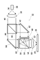
図2を参照するに、光学的な記録装置32は、光源34から照明レンズ38を経た光40を光42と光44とに分離する光分離器46と、光42の少なくとも1部を振幅変調するSLM48と、光44の少なくとも1部を位相変調するSLM50と、SLM48を透過した光52とSLM50を透過した光54とを合成する光合成器56と、合成された光58を被露光物26の面28に結像させる結像レンズ60とを含む。
【0035】
また、光分離器46からの光42を反射してSLM48へ導くミラー62と、光分離器46からの光44を反射してSLM50へ導くミラー64とが設けられている。
【0036】
露光用の光源として、通常のステッパーと同様に、超高圧水銀灯のi線やg線又はArFレーザ(波長=248mm)やKrFレーザ(波長=193mm)等のレーザ光を用いることができる。
【0037】
各SLM48、50は、1画素に対応する基本素子を複数配列した液晶素子を含み、半導体集積回路や液晶表示パネルの製造技術を用いて製造されている。
【0038】
SLM48とSLM50とは、記録装置32において、図示しない支持装置によって、光学的に並列に、かつ結像光学系すなわち結像レンズ60から見て重なり合う位置になるように支持されている。SLM14とSLM22との光軸方向の位置ずれは、それに対応して位相差すなわちP1(x,y)とP2(x,y)との差として生じるので、積算型の光学系と比べてより高精度に位置合わせが行われている。
【0039】
光分離器46及び光合成器56は、ハーフミラー型の光学要素が用いられている。光の合成においては、SLM48を透過した光とSLM50を透過した光とを光合成器56により干渉させている。偏光方向は同一である必要があるので、偏光ビームスプリッタを用いない。
【0040】
SLM48での複素振幅透過率をT1(x,y)、SLM50での複素振幅透過率をT2(x,y)とすると、被露光物26の面28での複素振幅E(x,y)は、以下の式(4)になる。
【0041】
【数4】
ここで、T1(x,y)、T2(x,y)は、以下の式(5)、(6)で定義される。
【0043】
【数5】
T1(x,y)≡A1(x,y)exp(iP1(x,y))・・・(5)
【0044】
【数6】
T2(x,y)≡A2(x,y)exp(iP2(x,y))・・・(6)
【0045】
上式(4)、(5)及び(6)に基づいて、上記の振幅A(x,y)及び位相P(x,y)が被露光物26の面28での最終的な振幅A(x,y)及び位相P(x,y)となるように、液晶素子への印加電圧で振幅変調(光の透過率)及び位相変調(位相0〜位相2π)を制御する。
【0046】
振幅変調用SLM48が位相変調作用を有していたり、位相変調用SLM50が振幅変調作用を有していたりする場合においても、前記の式(4)により最終的な振幅A(x,y)及び位相P(x,y)が理想値に近くなるように、T1(x,y、)、T2(x,y)の値を選択すればよい。
【0047】
振幅変調及び位相変調の量は任意の値をとりうるが、典型的な方法としては、振幅変調では、光の透過(以下「OFF」という。)、非透過(以下「ON」という。)及び半透過のいずれかに制御される。また、位相変調では、位相が同相である(以下「位相0」又は「OFF」という。)及び位相がπだけずれる(以下「位相π」又は「ON」という。)のいずれかに制御される。
【0048】
したがって、変調が行われる基本単位となる各液晶素子の画素に対して、少なくとも「非透過」、「半透過かつ位相π」、「透過かつ位相0」及び「透過かつ位相π」の4種類の場合が選択可能である。これらを組み合わせて任意の位相シフトマスクに準じる波面を形成することができる。ここで、「非透過」、「透過かつ位相0」及び「透過かつ位相π」はレベンソン型の位相シフトマスクに相当し、「半透過かつ位相π」及び「透過かつ位相0」はハーフトーン型の位相シフトマスクに相当する。
【0049】
図2においては、簡単にするために、2つのSLM48、50を透過した光を結合し、被露光物面に光を結像させるレンズ60を1つとして示したが、収差をなくすために複数のレンズを用いてもよい。また、両テレセントリックかつアフォーカル光学系にすれば、焦点がはずれても、露光パターンの寸法精度は保たれ、かつ均一な露光強度が得られる利点を有する。
【0050】
また、照明光学系として、ケーラー照明光学系やフライアイ(魚眼)レンズ等を用いるならば、均一な照度が得られ、全面で照明主光線をSLMの光入射面に対して垂直にすることができるので望ましい。特に、SLMとして液晶素子を用いた場合、液晶素子は入射角度により特性が大きく変わるので垂直照明が特に望ましい。空間光変調器として透過型の液晶素子を用いる場合で説明したが、それ以外の素子、例えば反射型の液晶素子やマイクロミラーデバイス等を用いることができる。また、液晶素子を含まない空間光変調器を用いることもできる。
【0051】
図3は積算型の光学系をより具体的に示すものである。記録装置66は、光源68と、光源68からの光70を反射するミラー72と、照明レンズ74、76を含む照明光学系78と、偏光板80、82及び液晶素子84を含む空間光変調器86と、等倍レンズ88、90及び絞り板92を含む等倍光学系94と、液晶素子96を含む空間光変調器98と、等倍レンズ100、絞り板102及び縮小レンズ104を含む縮小光学系106とを含む。
【0052】
光源として、Arレーザ(364nm)を用いた。このレーザをビームエキスパンダーで直径約50nmの平行光に拡大した。
【0053】
空間光変調器86は、入射した光を振幅変調する空間光変調器であり、透過性のTN配向型の液晶素子84の両面に2つの偏光板80、82を互いに偏光軸を直交させて配置している。この空間光変調器は、ノーマリホワイト型と呼ばれ、液晶素子84への印加電圧信号がONのときに非透過性を示す空間光変調器である。
【0054】
液晶素子84は、大きさが対角1.2インチ、画素数1024×768、画素サイズ25μm角のものを用いた。この液晶素子は、印加電圧信号がON/OFFのときに係る位相差が0になるように、液晶の厚さを3.1μmとして製造した。
【0055】
ただし、位相差を完全に0におさえることは難しく、いくらかの位相差は発生してしまう。後述するように、この位相差は、位相変調用の空間光変調器によって補正する。
【0056】
空間光変調器98は、入射した光を位相変調する空間光変調器であり、液晶素子96としてホモジニアス配向型の液晶素子を用いた。異方屈折率を有する液晶が電界により方向を変えることにより特定の偏光方向の光に対して屈折率が変化し、したがって、一定厚の液晶を透過した後の位相が変化するのが位相変調の原理である。
【0057】
液晶素子96は、液晶の屈折率異方性Δnを0.08、厚さを3.1μmとして製造した。印加電圧信号のON/OFF間で完全にダイレクタが90度変化すると仮定したときの位相変調は、以下の式(7)になり、この条件で任意の位相量を設定することができる。
【0058】
【数7】
位相変調用の空間光変調器98は、偏光板を用いず、液晶の配向をホモジニアス配向とした。また、液晶の厚さを3.1μmとして製造した。印加電圧信号がONのときに完全に垂直配向させた場合の位相差は2πとなる。予め、印加電圧と位相変調量との関係を求めて、印加電圧のON/OFFの制御を行った。
【0060】
結像光学系として、縮小率が100分の1、開口数(NA)が0.18のアフォーカルかつテレセントリックの光学系を用いた。被露光物面での画素サイズは0.25μm角となった。
【0061】
露光により記録すべき露光パターンとして渋谷レベンソン型の1.0μmのラインアンドスペース(以下「LアンドS」という。)テストパターンを用いて被露光物を露光した。比較用の露光パターンとして振幅変調のみの1.0μmのLアンドSテストパターンを用いて被露光物を露光した。各パターンを図4に示す。単位四角形がSLMの1つの画素を表す。寸法は結像面での値である。
【0062】
振幅変調で「OFF」は光の透過、「ON」は非透過を示す。位相変調で「OFF」は位相が同相(位相0)である、「ON」は位相がπだけずれている(位相π)ことを示す。振幅が非透過である部分の位相変調はON及びOFFのいずれでもよい。位相πの「ON」は位相変調がπになるような電圧を印加したことを示す。位相0と位相πのON及びOFFの位置はこの逆であってもよい。
【0063】
被露光物の基板としてシリコンウェハを用い、該シリコンウェハに東京応化工業製のフォトレジストTHMR−iP5700を1.0μm厚に塗布した。
【0064】
このフォトレジスト面を露光量40mJ/cm2で露光した。
【0065】
露光されたフォトレジストを現像処理して、フォトレジストに形成されたパターンを観察した。比較用のテストパターン(振幅変調のみのLアンドSテストパターン)においては、解像したものの線幅にばらつきがあったが、渋谷レベンソン型のLアンドSテストパターンにおいては、均一な線幅が得られ、良好な解像が認められた。
【0066】
本発明は、上記実施例に限定されず、その趣旨を逸脱しない限り、種々変更することができる。位相シフトマスクとして、実施例では「渋谷レベンソン型」について述べたが、一般の位相シフトマスクに用いられるいかなる型をも用いることができる。例えば「補助シフター型」、「エッジ強調型」、「シフターエッジ利用型」、「多段シフター型」、「ハーフトーン型」を用いることができる。
【図面の簡単な説明】
【図1】本発明に係る光学的な記録装置の実施例を示す図。
【図2】本発明に係る光学的な記録装置の他の実施例を示す図。
【図3】本発明に係る光学的な記録装置の実施例を示す図。
【図4】テストパターン及び比較用のテストパターンを示す図。
【符号の説明】
10、32、66 光学的な記録装置
14、22、48、50、86、98 空間光変調器
18、30、60 結像レンズ
26 被露光物
28 被露光物の面
38、74、76 照明レンズ
46 光分離手段
56 光合成手段
62、64、72 ミラー
78 照明光学系
80、82 偏光板
84、96 液晶素子
92、102 絞り板
94 等倍光学系
88、90、100 等倍レンズ
104 縮小レンズ
106 縮小光学系[0001]
BACKGROUND OF THE INVENTION
The present invention relates to an optical recording apparatus and recording method used in a photolithography process in the manufacture of a semiconductor integrated circuit, a liquid crystal display device, and the like, and an exposure apparatus and exposure method, and in particular, has a line width comparable to the wavelength of exposure light. The present invention relates to an optical recording apparatus and recording method, an exposure apparatus, and an exposure method that are suitable for forming an exposure pattern and the like.
[0002]
[Prior art]
As an optical recording apparatus by exposure, there is an exposure apparatus that forms an image of an exposure pattern on the surface of an object to be exposed by a projection optical system such as a lens projection or a mirror projection. However, when the line width of the exposure pattern is close to the wavelength of the exposure light, the line width was not resolved due to the light diffraction limit. In order to solve this problem, a phase shift mask having a transparent or translucent phase modulation layer called a shifter formed on a mask substrate is used as an exposure mask, and the phase is modulated by modulating the phase of light with the phase modulation layer. There is a way to improve it.
[0003]
As another exposure apparatus, there is a laser drawing apparatus, which exposes an object to be exposed while continuously or intermittently scanning the surface of the object with a laser beam according to an exposure pattern to be recorded. Furthermore, there is a laser drawing apparatus that uses a spatial light modulator that modulates the amplitude of light to image an exposure pattern formed by the spatial light modulator on an object to be exposed, and the exposure pattern is generated by the spatial light modulator for amplitude modulation. Can be recorded simultaneously in a plurality of locations, and therefore, there is an advantage that the drawing speed can be increased as compared with the case of scanning with a single beam.
[0004]
[Problems to be solved by the invention]
However, in the phase shift mask, the phase modulation layer needs to be formed on the mask substrate with a high precision thickness, and when the phase modulation layer and an amplitude modulation layer such as a patterned chromium film are combined, the phase modulation layer Since it is necessary to superimpose the layer and the amplitude modulation layer with high accuracy, it is more difficult to manufacture than an ordinary exposure mask, resulting in an increase in manufacturing cost. In addition, it is necessary to manufacture a phase shift mask for each pattern.
[0005]
Further, a laser drawing apparatus using a spatial light modulator for amplitude modulation can perform drawing at a high speed, but is inferior to an apparatus using a phase shift mask in terms of resolution.
[0006]
An object of the present invention is to provide an optical recording apparatus and method capable of obtaining a predetermined resolution and reducing the time required for exposure even when the line width of an exposure pattern is close to the wavelength of exposure light. is there.
[0007]
[Solution means, actions and effects for solving the problems]
An optical recording apparatus according to the present invention includes light conversion means for converting light from a light source into modulated light including amplitude-modulated light and phase-modulated light, and the modulated light on the surface of an object to be exposed. Imaging means for forming an image.
[0008]
An optical recording method according to the present invention includes a step of converting light from a light source into modulated light including amplitude-modulated light and phase-modulated light, and imaging the modulated light on an object to be exposed. And a step of causing.
[0009]
In such a recording apparatus and method, modulated light including amplitude-modulated light and phase-modulated light is imaged on the surface of the object to be exposed. Therefore, the amplitude modulation and the phase modulation can be simultaneously performed in recording the exposure pattern on the exposure object by exposure, and the same high resolution and shortening of the exposure time as the phase shift mask can be easily realized. Since the modulation of the phase and amplitude is easy to control, the optimum modulation amount can be easily set. In addition, there is basically no need to replace the exposure mask each time the exposure pattern is changed.
[0010]
Preferably, the light converting means forms an image of a first spatial light modulator that amplitude-modulates at least a part of light guided from the light source, and light modulated by the first spatial light modulator. A first imaging optical system; and a second spatial light modulator that phase-modulates at least a part of the light imaged by the first imaging optical system. A second imaging optical system for imaging light modulated by the two spatial light modulators on the surface of the object to be exposed;
[0011]
The light converting means includes a first spatial light modulator that phase-modulates at least a part of light guided from the light source, and a first light that forms an image of the light modulated by the first spatial light modulator. An imaging optical system; and a second spatial light modulator that amplitude-modulates at least a part of the light imaged by the first imaging optical system, wherein the imaging means includes the second space. A second imaging optical system that forms an image of the light modulated by the optical modulator on the surface of the object to be exposed may be included.
[0012]
The light converting means includes a light separating means for separating the light guided from the light source into a first light and a second light, and a first spatial light for amplitude-modulating at least a part of the first light. A modulator, a second spatial light modulator that phase-modulates at least a portion of the second light, light modulated by the first spatial light modulator, and modulation by the second spatial light modulator Light combining means for combining the combined light, and the image forming means may include an image forming optical system for forming an image of the combined light on the surface of the object to be exposed.
[0013]
The spatial light modulator for amplitude modulation may preferably include a polarizing plate and a liquid crystal spatial light modulator. The spatial light modulator that performs phase modulation may preferably include a liquid crystal spatial light modulator.
[0014]
The imaging optical system that forms an image on the surface of the object to be exposed can preferably be a reduction optical system.
[0015]
Preferably, the converting step includes the step of causing the light from the light source to enter a first spatial light modulator that amplitude-modulates at least a portion of the light and modulated by the first spatial light modulator. A step of imaging light by the first imaging optical system, and the light imaged by the first imaging optical system is incident on a second spatial light modulator that phase-modulates at least a part of the light And the step of forming an image may include the step of forming an image of the light modulated by the second spatial light modulator on the surface of the object to be exposed.
[0016]
The converting step includes the step of causing the light from the light source to enter a first spatial light modulator that phase-modulates at least a part of the light, and the light modulated by the first spatial light modulator to Forming an image with one imaging optical system, and causing the light imaged with the first imaging optical system to enter a second spatial light modulator that amplitude-modulates at least a part of the light; And the step of forming an image may include the step of forming an image of the light modulated by the second spatial light modulator on the surface of the object to be exposed.
[0017]
The converting step includes a step of separating light from the light source into first light and second light by light separating means, and first amplitude-modulating at least part of the first light. Incident on the second spatial light modulator, entering the second light into a second spatial light modulator that phase-modulates at least a portion of the light, and modulating the first spatial light modulator. And combining the light modulated by the second spatial light modulator by a light combining means, and forming the image on the surface of the object to be exposed. The step to make may be included.
[0018]
In the recording method according to the present invention, the modulation is performed on the surface of the object to be exposed while scanning continuously or intermittently while changing the exposure pattern formed by the light conversion and the position where the surface of the object to be exposed is exposed. A final exposure pattern can be formed by imaging light.
[0019]
DETAILED DESCRIPTION OF THE INVENTION
First, an integrating optical storage device and method for optically coupling a spatial light modulator for amplitude modulation and a spatial light modulator for phase modulation optically in series will be described.
[0020]
Referring to FIG. 1, an
[0021]
As a light source for exposure, i-line or g-line of an ultra-high pressure mercury lamp or various kinds of laser light can be used as in a normal projection exposure apparatus.
[0022]
Each of the
[0023]
The
[0024]
Assuming that the complex amplitude transmittance at the
[0025]
[Expression 1]
Here, T 1 (x, y) and T 2 (x, y) are defined by the following equations (2) and (3).
[0027]
[Expression 2]
T 1 (x, y) ≡A 1 (x, y) exp (iP 1 (x, y)) (2)
[0028]
[Equation 3]
T 2 (x, y) ≡A 2 (x, y) exp (iP 2 (x, y)) (3)
[0029]
Based on the above equations (1), (2), and (3), the amplitude A (x, y) and the phase P (x, y) described above are the final amplitude A ( Amplitude modulation (light transmittance) and phase modulation (phase 0 to phase 2π) are controlled by a voltage applied to the liquid crystal element so that x, y) and phase P (x, y) are obtained.
[0030]
Even when the
[0031]
The
[0032]
In FIG. 1, the case where the SLM for amplitude modulation is arranged on the light source side and the SLM for phase modulation is arranged on the exposed object side is explained in FIG. 1, but the phase modulation SLM is arranged on the light source side and the amplitude modulation SLM is covered. Even when it is arranged on the exposed object side, it is the same as above. A spatial light modulator that does not include a liquid crystal element can also be used.
[0033]
Next, an addition-type optical storage device and method for optically coupling the spatial light modulator for amplitude modulation and the spatial light modulator for phase modulation in parallel will be described.
[0034]
Referring to FIG. 2, the
[0035]
Further, a
[0036]
As an exposure light source, an i-line or g-line of an ultra-high pressure mercury lamp, or a laser beam such as an ArF laser (wavelength = 248 mm) or a KrF laser (wavelength = 193 mm) can be used as in a normal stepper.
[0037]
Each
[0038]
The
[0039]
The
[0040]
When the complex amplitude transmittance at the
[0041]
[Expression 4]
Here, T 1 (x, y) and T 2 (x, y) are defined by the following equations (5) and (6).
[0043]
[Equation 5]
T 1 (x, y) ≡A 1 (x, y) exp (iP 1 (x, y)) (5)
[0044]
[Formula 6]
T 2 (x, y) ≡A 2 (x, y) exp (iP 2 (x, y)) (6)
[0045]
Based on the above equations (4), (5), and (6), the amplitude A (x, y) and the phase P (x, y) described above are the final amplitude A (on the
[0046]
Even when the
[0047]
The amount of amplitude modulation and phase modulation can take any value, but as a typical method, in amplitude modulation, light transmission (hereinafter referred to as “OFF”), non-transmission (hereinafter referred to as “ON”), and It is controlled to either semi-transmissive. In the phase modulation, the phase is controlled to be in phase (hereinafter referred to as “phase 0” or “OFF”) and the phase is shifted by π (hereinafter referred to as “phase π” or “ON”). .
[0048]
Therefore, at least four types of “non-transmission”, “semi-transmission and phase π”, “transmission and phase 0”, and “transmission and phase π” are applied to the pixels of each liquid crystal element that is a basic unit for modulation The case is selectable. A wavefront conforming to an arbitrary phase shift mask can be formed by combining these. Here, “non-transmission”, “transmission and phase 0” and “transmission and phase π” correspond to a Levenson type phase shift mask, and “semi-transmission and phase π” and “transmission and phase 0” are halftone types. This corresponds to the phase shift mask.
[0049]
In FIG. 2, for the sake of simplicity, a
[0050]
Further, if a Koehler illumination optical system, a fly-eye (fisheye) lens, or the like is used as the illumination optical system, uniform illuminance can be obtained, and the illumination principal ray should be perpendicular to the light incident surface of the SLM over the entire surface. This is desirable. In particular, when a liquid crystal element is used as the SLM, vertical illumination is particularly desirable because the liquid crystal element has characteristics that vary greatly depending on the incident angle. Although the case where a transmissive liquid crystal element is used as the spatial light modulator has been described, other elements such as a reflective liquid crystal element or a micromirror device can be used. A spatial light modulator that does not include a liquid crystal element can also be used.
[0051]
FIG. 3 shows the integration type optical system more specifically. The
[0052]
An Ar laser (364 nm) was used as the light source. This laser was expanded to parallel light having a diameter of about 50 nm by a beam expander.
[0053]
The spatial
[0054]
A liquid crystal element 84 having a diagonal size of 1.2 inches, a pixel number of 1024 × 768, and a pixel size of 25 μm square was used. The liquid crystal element was manufactured with a liquid crystal thickness of 3.1 μm so that the phase difference is 0 when the applied voltage signal is ON / OFF.
[0055]
However, it is difficult to completely reduce the phase difference to zero, and some phase difference occurs. As will be described later, this phase difference is corrected by a spatial light modulator for phase modulation.
[0056]
The spatial
[0057]
The
[0058]
[Expression 7]
The spatial
[0060]
As the imaging optical system, an afocal and telecentric optical system having a reduction ratio of 1/100 and a numerical aperture (NA) of 0.18 was used. The pixel size on the surface of the object to be exposed was 0.25 μm square.
[0061]
The exposed object was exposed using a 1.0 μm line and space (hereinafter referred to as “L and S”) test pattern of Shibuya Levenson type as an exposure pattern to be recorded by exposure. The object to be exposed was exposed using a 1.0 μm L and S test pattern with only amplitude modulation as an exposure pattern for comparison. Each pattern is shown in FIG. A unit square represents one pixel of the SLM. The dimensions are values at the image plane.
[0062]
In amplitude modulation, “OFF” indicates light transmission and “ON” indicates non-transmission. In the phase modulation, “OFF” indicates that the phase is in phase (phase 0), and “ON” indicates that the phase is shifted by π (phase π). The phase modulation of the portion where the amplitude is non-transmissive may be either ON or OFF. “ON” of the phase π indicates that a voltage is applied so that the phase modulation becomes π. The ON and OFF positions of phase 0 and phase π may be reversed.
[0063]
A silicon wafer was used as the substrate of the object to be exposed, and a photoresist THMR-iP5700 manufactured by Tokyo Ohka Kogyo Co., Ltd. was applied to the silicon wafer to a thickness of 1.0 μm.
[0064]
The photoresist surface was exposed at an exposure amount of 40 mJ / cm 2 .
[0065]
The exposed photoresist was developed and the pattern formed on the photoresist was observed. In the test pattern for comparison (L and S test pattern with amplitude modulation only), the line width of the resolved ones varied, but in the Shibuya Levenson type L and S test pattern, a uniform line width was obtained. And good resolution was observed.
[0066]
The present invention is not limited to the above embodiment, and various modifications can be made without departing from the spirit of the present invention. As the phase shift mask, the “Shibuya Levenson type” has been described in the embodiment, but any type used for a general phase shift mask can be used. For example, “auxiliary shifter type”, “edge enhancement type”, “shifter edge utilization type”, “multistage shifter type”, and “halftone type” can be used.
[Brief description of the drawings]
FIG. 1 is a diagram showing an embodiment of an optical recording apparatus according to the present invention.
FIG. 2 is a diagram showing another embodiment of the optical recording apparatus according to the invention.
FIG. 3 is a diagram showing an embodiment of an optical recording apparatus according to the present invention.
FIG. 4 is a diagram showing a test pattern and a test pattern for comparison.
[Explanation of symbols]
10, 32, 66
Claims (14)
前記光変換手段は、前記光源から導かれた光の少なくとも1部を振幅変調又は位相変調する第1の空間光変調器であって前記振幅変調量又は位相変調量を制御可能な第1の空間光変調器と、前記第1の空間光変調器で変調された光を結像させる第1の結像光学系と、前記第1の結像光学系の結像位置に設けられ前記第1の結像光学系により結像された光の少なくとも1部を位相変調又は振幅変調する第2の空間光変調器であって前記位相変調量又は振幅変調量を制御可能な第2の空間光変調器とを含み、前記結像手段は、前記第2の空間光変調器で変調された光を前記被露光物面に結像させる第2の結像光学系を含む、光学的な記録装置。Light converting means for converting light from the light source into modulated light including amplitude-modulated light and phase-modulated light to form a wavefront conforming to the phase shift mask; and the modulated light on the surface of the object to be exposed Imaging means for imaging,
The light converting means is a first spatial light modulator that amplitude-modulates or phase-modulates at least a part of light guided from the light source, and is a first space capable of controlling the amplitude modulation amount or phase modulation amount. An optical modulator; a first imaging optical system that forms an image of light modulated by the first spatial light modulator; and the first imaging optical system provided at an imaging position of the first imaging optical system. A second spatial light modulator capable of phase-modulating or amplitude-modulating at least a part of light imaged by the imaging optical system, wherein the phase-modulation amount or amplitude-modulation amount can be controlled. And the imaging means includes a second imaging optical system that images the light modulated by the second spatial light modulator on the surface of the object to be exposed.
前記光変換手段は、前記光源から導かれた光を第1の光と第2の光とに分離する光分離手段と、前記第1の光の少なくとも1部を振幅変調する第1の空間光変調器であって前記振幅変調量を制御可能な第1の空間光変調器と、前記第2の光の少なくとも1部を位相変調する第2の空間光変調器であって前記位相変調量を制御可能な第2の空間光変調器と、前記第1の空間光変調器で変調された光と前記第2の空間光変調器で変調された光とを合成する光合成手段とを含み、
前記結像手段は、前記合成された光を前記被露光物面に結像させる結像光学系を含む、光学的な記録装置。Light converting means for converting light from the light source into modulated light including amplitude-modulated light and phase-modulated light to form a wavefront conforming to the phase shift mask; and the modulated light on the surface of the object to be exposed Imaging means for imaging,
The light converting means includes a light separating means for separating the light guided from the light source into a first light and a second light, and a first spatial light for amplitude-modulating at least a part of the first light. A first spatial light modulator capable of controlling the amplitude modulation amount, and a second spatial light modulator that phase-modulates at least a part of the second light, wherein the phase modulation amount is A controllable second spatial light modulator; and light combining means for combining the light modulated by the first spatial light modulator and the light modulated by the second spatial light modulator,
The image forming means includes an image forming optical system that forms an image of the combined light on the surface of the object to be exposed.
前記光変換するステップは、前記光源からの光を該光の少なくとも1部を振幅変調又は位相変調する第1の空間光変調器であって前記振幅変調量又は位相変調量を制御可能な第1の空間光変調器によって振幅変調量又は位相変調量を制御する振幅変調量制御ステップ又は位相変調量制御ステップと、前記第1の空間光変調器で変調された光を第1の結像光学系により結像させるステップと、前記第1の結像光学系により結像された光を該光の少なくとも1部を位相変調又は振幅変調する第2の空間光変調器であって前記位相変調量又は振幅変調量を制御可能な第2の空間光変調器によって位相変調量又は振幅変調量を制御する位相変調量制御ステップ又は振幅変調量制御ステップとを含み、
前記結像させるステップは、前記第2の空間光変調器で変調された光を前記被露光物面に結像させるステップを含む、光学的な記録方法。Converting the light from the light source into modulated light including amplitude-modulated light and phase-modulated light to form a wavefront conforming to the phase shift mask; and concatenating the modulated light on the surface of the object to be exposed. And imaging
The light converting step is a first spatial light modulator that amplitude-modulates or phase-modulates at least a part of the light from the light source, and is capable of controlling the amplitude modulation amount or the phase modulation amount. An amplitude modulation amount control step or a phase modulation amount control step for controlling an amplitude modulation amount or a phase modulation amount by the spatial light modulator, and a first imaging optical system for the light modulated by the first spatial light modulator And a second spatial light modulator that phase-modulates or amplitude-modulates at least part of the light imaged by the first imaging optical system, the phase modulation amount or A phase modulation amount control step or an amplitude modulation amount control step of controlling the phase modulation amount or the amplitude modulation amount by a second spatial light modulator capable of controlling the amplitude modulation amount,
The optical imaging method includes the step of imaging the light modulated by the second spatial light modulator on the surface of the object to be exposed.
前記光変換するステップは、前記光源からの光を光分離手段により第1の光と第2の光とに分離するステップと、前記第1の光の少なくとも1部を振幅変調する第1の空間光変調器であって前記振幅変調量を制御可能な第1の空間光変調器によって振幅変調量を制御する振幅変調量制御ステップと、前記第2の光の少なくとも1部を位相変調する第2の空間光変調器であって前記位相変調量を制御可能な第2の空間光変調器によって位相変調量を制御する位相変調量制御ステップと、前記第1の空間光変調器で変調された光と前記第2の空間光変調器で変調された光とを光合成手段により合成するステップとを含み、
前記結像させるステップは、前記合成された光を前記被露光物面に結像させるステップを含む、光学的な記録方法。Light-converting light from the light source into modulated light including amplitude-modulated light and phase-modulated light to form a wavefront conforming to the phase shift mask; and linking the modulated light to the surface of the object to be exposed And imaging
The light converting step includes a step of separating light from the light source into first light and second light by light separating means, and a first space for amplitude-modulating at least a part of the first light. An amplitude modulation amount control step of controlling the amplitude modulation amount by a first spatial light modulator capable of controlling the amplitude modulation amount, and a second phase modulating at least a part of the second light; A phase modulation amount control step of controlling the phase modulation amount by a second spatial light modulator capable of controlling the phase modulation amount, and light modulated by the first spatial light modulator Combining the light modulated by the second spatial light modulator by light combining means,
The image forming step includes the step of forming an image of the combined light on the surface of the object to be exposed.
前記光変換するステップは、前記光源からの光の振幅変調量又は位相変調量を制御可能な第1の空間光変調器によって振幅変調量又は位相変調量を制御する振幅変調量制御ステップ又は位相変調量制御ステップと、前記光源からの光の位相変調量又は振幅変調量を制御可能な第2の空間光変調器によって位相変調量又は振幅変調量を制御する位相変調量制御ステップ又は振幅変調量制御ステップとを含み、
前記光変換により形成される露光パターンと前記被露光物面が露光される箇所とを変えながら連続的又は間欠的に走査しながら前記被露光物面に前記変調光を結像させることにより最終の露光パターンを形成する、光学的な記録方法。Converting the light from the light source into modulated light including amplitude-modulated light and phase-modulated light to form a wavefront conforming to the phase shift mask; and concatenating the modulated light on the surface of the object to be exposed. And imaging
The step of converting light includes an amplitude modulation amount control step or phase modulation in which the amplitude modulation amount or phase modulation amount is controlled by a first spatial light modulator capable of controlling the amplitude modulation amount or phase modulation amount of light from the light source. And a phase modulation amount control step or amplitude modulation amount control for controlling the phase modulation amount or amplitude modulation amount by a second spatial light modulator capable of controlling the phase modulation amount or amplitude modulation amount of light from the light source. Including steps,
A final image is formed by imaging the modulated light on the surface of the object while continuously or intermittently scanning while changing the exposure pattern formed by the light conversion and the position where the surface of the object is exposed. An optical recording method for forming an exposure pattern.
前記光変換手段は、前記光源から導かれた光の少なくとも1部を振幅変調又は位相変調する第1の空間光変調器であって前記振幅変調量又は位相変調量を制御可能な第1の空間光変調器と、前記第1の空間光変調器で変調された光を結像させる第1の結像光学系と、前記第1の結像光学系に設けられ前記第1の結像光学系により結像された光の少なくとも1部を位相変調又は振幅変調する第2の空間光変調器であって前記位相変調量又は振幅変調量を制御可能な第2の空間光変調器とを含み、前記結像手段は、前記第2の空間光変調器で変調された光を前記被露光物面に結像させる第2の結像光学系を含む、露光装置。Light converting means for converting light from the light source into modulated light including amplitude-modulated light and phase-modulated light to form a wavefront conforming to the phase shift mask; and the modulated light on the surface of the object to be exposed Imaging means for imaging,
The light converting means is a first spatial light modulator that amplitude-modulates or phase-modulates at least a part of light guided from the light source, and is a first space capable of controlling the amplitude modulation amount or phase modulation amount. An optical modulator; a first imaging optical system that images light modulated by the first spatial light modulator; and the first imaging optical system provided in the first imaging optical system. A second spatial light modulator that phase-modulates or amplitude-modulates at least a part of the light imaged by the second spatial light modulator capable of controlling the phase modulation amount or the amplitude modulation amount, The image forming means includes an exposure apparatus including a second image forming optical system that forms an image of the light modulated by the second spatial light modulator on the surface of the object to be exposed.
前記光変換手段は、前記光源から導かれた光を第1の光と第2の光とに分離する光分離手段と、前記第1の光の少なくとも1部を振幅変調する第1の空間光変調器であって前記振幅変調量を制御可能な第1の空間光変調器と、前記第2の光の少なくとも1部を位相変調する第2の空間光変調器であって前記位相変調量を制御可能な第2の空間光変調器と、前記第1の空間光変調器で変調された光と前記第2の空間光変調器で変調された光とを合成する光合成手段とを含み、
前記結像手段は、前記合成された光を前記被露光物面に結像させる結像光学系を含む、露光装置。Light converting means for converting light from the light source into modulated light including amplitude-modulated light and phase-modulated light to form a wavefront conforming to the phase shift mask; and the modulated light on the surface of the object to be exposed Imaging means for imaging,
The light converting means includes a light separating means for separating the light guided from the light source into a first light and a second light, and a first spatial light for amplitude-modulating at least a part of the first light. A first spatial light modulator capable of controlling the amplitude modulation amount, and a second spatial light modulator that phase-modulates at least a part of the second light, wherein the phase modulation amount is A controllable second spatial light modulator; and light combining means for combining the light modulated by the first spatial light modulator and the light modulated by the second spatial light modulator,
The image forming means includes an image forming optical system that forms an image of the combined light on the surface of the object to be exposed.
前記光変換するステップは、前記光源からの光の少なくとも1部を振幅変調又は位相変調する第1の空間光変調器であって前記振幅変調量又は位相変調量を制御可能な第1の空間光変調器によって振幅変調量又は位相変調量を制御する振幅変調量制御ステップ又は位相変調量制御ステップと、前記第1の空間光変調器で変調された光を第1の結像光学系により結像させるステップと、前記第1の結像光学系の結像位置に設けられ前記第1の結像光学系により結像された光の少なくとも1部を位相変調又は振幅変調する第2の空間光変調器であって前記位相変調量又は振幅変調量を制御可能な第2の空間光変調器によって位相変調量又は振幅変調量を制御する位相変調量制御ステップ又は振幅変調量制御ステップとを含み、
前記結像させるステップは、前記第2の空間光変調器で変調された光を前記被露光物面に結像させるステップを含む、露光方法。Converting light from a light source into modulated light including amplitude-modulated light and phase-modulated light to form a wavefront conforming to a phase shift mask; and imaging the modulated light on the surface of an object to be exposed And a step of causing
The light converting step is a first spatial light modulator that amplitude-modulates or phase-modulates at least a part of the light from the light source, and is capable of controlling the amplitude modulation amount or phase modulation amount. An amplitude modulation amount control step or a phase modulation amount control step for controlling the amplitude modulation amount or the phase modulation amount by the modulator, and the light modulated by the first spatial light modulator is imaged by the first imaging optical system And a second spatial light modulation for phase-modulating or amplitude-modulating at least a part of the light imaged by the first imaging optical system provided at the imaging position of the first imaging optical system A phase modulation amount control step or an amplitude modulation amount control step for controlling the phase modulation amount or the amplitude modulation amount by a second spatial light modulator capable of controlling the phase modulation amount or the amplitude modulation amount,
The image forming step includes the step of forming an image of the light modulated by the second spatial light modulator on the surface of the object to be exposed.
前記光変換するステップは、前記光源からの光を光分離手段により第1の光と第2の光とに分離するステップと、前記第1の光の少なくとも1部を振幅変調する第1の空間光変調器であって該第1の空間変調器によって振幅変調量を制御する振幅変調量制御ステップと、前記第2の光の少なくとも1部を位相変調する第2の空間光変調器であって該第2の空間変調器によって位相変調量を制御する位相変調量制御ステップと、前記第1の空間光変調器で変調された光と前記第2の空間光変調器で変調された光とを光合成手段により合成するステップとを含み、
前記結像させるステップは、前記合成された光を前記被露光物面に結像させるステップを含む、露光方法。Converting light from a light source into modulated light including amplitude-modulated light and phase-modulated light to form a wavefront conforming to a phase shift mask; and imaging the modulated light on the surface of an object to be exposed And a step of causing
The light converting step includes a step of separating light from the light source into first light and second light by light separating means, and a first space for amplitude-modulating at least a part of the first light. An optical modulator, an amplitude modulation amount control step for controlling an amplitude modulation amount by the first spatial modulator, and a second spatial light modulator for phase modulating at least a part of the second light. A phase modulation amount control step for controlling a phase modulation amount by the second spatial light modulator, light modulated by the first spatial light modulator and light modulated by the second spatial light modulator. Synthesizing by photosynthesis means,
The image forming step includes the step of forming an image of the combined light on the surface of the object to be exposed.
前記光変換するステップは、前記光源からの光の振幅変調量又は位相変調量を制御可能な第1の空間光変調器によって振幅変調量又は位相変調量を制御する振幅変調量制御ステップ又は位相変調量制御ステップと、前記光源からの光の位相変調量又は振幅変調量を制御可能な第2の空間光変調器によって位相変調量又は振幅変調量を制御する位相変調量制御ステップ又は振幅変調量制御ステップとを含み、
前記光変換により形成される露光パターンと前記被露光物面が露光される箇所とを変えながら連続的又は間欠的に走査しながら前記被露光物面に前記変調光を結像させることにより最終の露光パターンを形成する、露光方法。Converting light from a light source into modulated light including amplitude-modulated light and phase-modulated light to form a wavefront conforming to a phase shift mask; and imaging the modulated light on the surface of an object to be exposed And a step of causing
The step of converting light includes an amplitude modulation amount control step or phase modulation in which the amplitude modulation amount or phase modulation amount is controlled by a first spatial light modulator capable of controlling the amplitude modulation amount or phase modulation amount of light from the light source. And a phase modulation amount control step or amplitude modulation amount control for controlling the phase modulation amount or amplitude modulation amount by a second spatial light modulator capable of controlling the phase modulation amount or amplitude modulation amount of light from the light source. Including steps,
A final image is formed by imaging the modulated light on the surface of the object while continuously or intermittently scanning while changing the exposure pattern formed by the light conversion and the position where the surface of the object is exposed. An exposure method for forming an exposure pattern.
Priority Applications (6)
| Application Number | Priority Date | Filing Date | Title |
|---|---|---|---|
| JP2001322598A JP3881865B2 (en) | 2001-10-19 | 2001-10-19 | Optical recording apparatus and method, and exposure apparatus and method |
| US10/241,676 US6900827B2 (en) | 2001-10-19 | 2002-09-10 | Optical recorder and method thereof |
| KR10-2002-0056305A KR100478625B1 (en) | 2001-10-19 | 2002-09-17 | Optical Recorder and Method Thereof |
| DE10243559A DE10243559B4 (en) | 2001-10-19 | 2002-09-19 | Photolithography exposure apparatus and photolithography exposure method |
| CNB021438196A CN1238767C (en) | 2001-10-19 | 2002-09-25 | Optical recorder and recording method thereof |
| SE0202949A SE521230C2 (en) | 2001-10-19 | 2002-10-07 | Optical recorder and method thereof |
Applications Claiming Priority (1)
| Application Number | Priority Date | Filing Date | Title |
|---|---|---|---|
| JP2001322598A JP3881865B2 (en) | 2001-10-19 | 2001-10-19 | Optical recording apparatus and method, and exposure apparatus and method |
Publications (3)
| Publication Number | Publication Date |
|---|---|
| JP2003133201A JP2003133201A (en) | 2003-05-09 |
| JP2003133201A5 JP2003133201A5 (en) | 2005-06-30 |
| JP3881865B2 true JP3881865B2 (en) | 2007-02-14 |
Family
ID=19139621
Family Applications (1)
| Application Number | Title | Priority Date | Filing Date |
|---|---|---|---|
| JP2001322598A Expired - Fee Related JP3881865B2 (en) | 2001-10-19 | 2001-10-19 | Optical recording apparatus and method, and exposure apparatus and method |
Country Status (6)
| Country | Link |
|---|---|
| US (1) | US6900827B2 (en) |
| JP (1) | JP3881865B2 (en) |
| KR (1) | KR100478625B1 (en) |
| CN (1) | CN1238767C (en) |
| DE (1) | DE10243559B4 (en) |
| SE (1) | SE521230C2 (en) |
Families Citing this family (21)
| Publication number | Priority date | Publication date | Assignee | Title |
|---|---|---|---|---|
| US6794100B2 (en) * | 2001-08-30 | 2004-09-21 | Micron Technology, Inc. | Method for controlling radiation beam intensity directed to microlithographic substrates |
| US6784975B2 (en) * | 2001-08-30 | 2004-08-31 | Micron Technology, Inc. | Method and apparatus for irradiating a microlithographic substrate |
| CA2581660A1 (en) * | 2003-09-26 | 2005-04-07 | Tidal Photonics, Inc. | Apparatus and methods relating to precision control of illumination exposure |
| US6894765B2 (en) * | 2003-10-14 | 2005-05-17 | Micron Technology, Inc. | Methods and systems for controlling radiation beam characteristics for microlithographic processing |
| JP2007522671A (en) * | 2004-02-25 | 2007-08-09 | マイクロニック レーザー システムズ アクチボラゲット | Method for exposing a pattern and emulating a mask in optical maskless lithography |
| JP4750396B2 (en) * | 2004-09-27 | 2011-08-17 | キヤノン株式会社 | Exposure apparatus and device manufacturing method |
| US7446855B2 (en) * | 2005-07-25 | 2008-11-04 | Micron Technology, Inc | Methods and apparatuses for configuring radiation in microlithographic processing of workpieces using an adjustment structure |
| US20070153249A1 (en) * | 2005-12-20 | 2007-07-05 | Asml Netherlands B.V. | Lithographic apparatus and device manufacturing method using multiple exposures and multiple exposure types |
| US7838178B2 (en) * | 2007-08-13 | 2010-11-23 | Micron Technology, Inc. | Masks for microlithography and methods of making and using such masks |
| CN101796460B (en) | 2007-08-30 | 2013-05-01 | 卡尔蔡司Smt有限责任公司 | Illumination system for illuminating a mask in a microlithographic projection exposure apparatus |
| US8451427B2 (en) | 2007-09-14 | 2013-05-28 | Nikon Corporation | Illumination optical system, exposure apparatus, optical element and manufacturing method thereof, and device manufacturing method |
| US8379187B2 (en) * | 2007-10-24 | 2013-02-19 | Nikon Corporation | Optical unit, illumination optical apparatus, exposure apparatus, and device manufacturing method |
| KR101010263B1 (en) * | 2008-05-31 | 2011-01-26 | 최리나 | Slippers having duster |
| US8368994B2 (en) * | 2008-06-28 | 2013-02-05 | Alces Technology, Inc. | Scanned, one-dimensional, phased-array display system |
| WO2010024106A1 (en) * | 2008-08-28 | 2010-03-04 | 株式会社ニコン | Illumination optical system, aligner, and process for fabricating device |
| JP2010182934A (en) * | 2009-02-06 | 2010-08-19 | Dainippon Screen Mfg Co Ltd | Drawing apparatus and drawing method |
| JP5532213B2 (en) * | 2009-12-07 | 2014-06-25 | 株式会社ニコン | Illumination optical system, exposure apparatus, and device manufacturing method |
| JP6137485B2 (en) * | 2012-01-18 | 2017-05-31 | 株式会社ニコン | Exposure method and apparatus, and device manufacturing method |
| JP6193963B2 (en) * | 2015-12-18 | 2017-09-06 | カール・ツァイス・エスエムティー・ゲーエムベーハー | Illumination system for illuminating a mask in a microlithographic projection exposure apparatus |
| US10489924B2 (en) * | 2016-03-30 | 2019-11-26 | Samsung Electronics Co., Ltd. | Structured light generator and object recognition apparatus including the same |
| CN116068860A (en) | 2021-11-04 | 2023-05-05 | 邱俊荣 | Exposure apparatus and exposure method |
Family Cites Families (21)
| Publication number | Priority date | Publication date | Assignee | Title |
|---|---|---|---|---|
| BE425160A (en) | 1936-12-12 | |||
| US4205348A (en) * | 1978-07-05 | 1980-05-27 | Xerox Corporation | Laser scanning utilizing facet tracking and acousto pulse imaging techniques |
| JPH04293013A (en) * | 1991-03-22 | 1992-10-16 | Seiko Epson Corp | Optical device |
| EP0657760A1 (en) * | 1993-09-15 | 1995-06-14 | Texas Instruments Incorporated | Image simulation and projection system |
| US5539567A (en) * | 1994-06-16 | 1996-07-23 | Texas Instruments Incorporated | Photolithographic technique and illuminator using real-time addressable phase shift light shift |
| JPH0822939A (en) * | 1994-07-05 | 1996-01-23 | Fujitsu Ltd | Pattern exposure method and pattern exposure device |
| US6229649B1 (en) * | 1994-10-04 | 2001-05-08 | The United States Of America As Represented By The Secretary Of The Air Force | Pseudo deconvolution method of recovering a distorted optical image |
| JP3594384B2 (en) | 1995-12-08 | 2004-11-24 | ソニー株式会社 | Semiconductor exposure apparatus, projection exposure apparatus, and circuit pattern manufacturing method |
| US5757505A (en) * | 1996-02-16 | 1998-05-26 | Nikon Corporation | Exposure apparatus |
| US5923359A (en) * | 1997-03-14 | 1999-07-13 | Cymbolic Sciences International Inc. | Internal drum scophony raster recording device |
| US5754514A (en) * | 1996-10-08 | 1998-05-19 | Polaroid Corporation | Phase controlled evanescent field systems and methods for optical recording and retrieval |
| US6291110B1 (en) * | 1997-06-27 | 2001-09-18 | Pixelligent Technologies Llc | Methods for transferring a two-dimensional programmable exposure pattern for photolithography |
| SE9800665D0 (en) | 1998-03-02 | 1998-03-02 | Micronic Laser Systems Ab | Improved method for projection printing using a micromirror SLM |
| HU9801029D0 (en) * | 1998-05-05 | 1998-06-29 | Optilink Ab | Method and system for recording information on a holographic card |
| JP2000021742A (en) * | 1998-06-30 | 2000-01-21 | Canon Inc | Method of exposure and exposure equipment |
| JP4199332B2 (en) | 1998-07-31 | 2008-12-17 | 凸版印刷株式会社 | Method for producing hologram |
| JP2001168003A (en) * | 1999-12-06 | 2001-06-22 | Olympus Optical Co Ltd | Aligner |
| JP2001185476A (en) * | 1999-12-27 | 2001-07-06 | Mitsubishi Electric Corp | Exporsure projection equipment |
| JP3762186B2 (en) | 2000-04-10 | 2006-04-05 | 株式会社フジクラ | Optical transmission line and optical transmission line with optical line monitoring device |
| KR100603523B1 (en) | 2000-12-29 | 2006-07-24 | 엘지전자 주식회사 | Vacuum cleaner |
| US6577428B2 (en) * | 2001-03-27 | 2003-06-10 | The Regents Of The University Of California | Optical electric-field pattern generator |
-
2001
- 2001-10-19 JP JP2001322598A patent/JP3881865B2/en not_active Expired - Fee Related
-
2002
- 2002-09-10 US US10/241,676 patent/US6900827B2/en not_active Expired - Fee Related
- 2002-09-17 KR KR10-2002-0056305A patent/KR100478625B1/en not_active IP Right Cessation
- 2002-09-19 DE DE10243559A patent/DE10243559B4/en not_active Expired - Fee Related
- 2002-09-25 CN CNB021438196A patent/CN1238767C/en not_active Expired - Fee Related
- 2002-10-07 SE SE0202949A patent/SE521230C2/en not_active IP Right Cessation
Also Published As
| Publication number | Publication date |
|---|---|
| KR20030032837A (en) | 2003-04-26 |
| SE0202949D0 (en) | 2002-10-07 |
| CN1238767C (en) | 2006-01-25 |
| DE10243559B4 (en) | 2007-02-01 |
| KR100478625B1 (en) | 2005-03-28 |
| SE0202949L (en) | 2003-04-20 |
| DE10243559A1 (en) | 2003-05-08 |
| US20030076404A1 (en) | 2003-04-24 |
| US6900827B2 (en) | 2005-05-31 |
| JP2003133201A (en) | 2003-05-09 |
| CN1412621A (en) | 2003-04-23 |
| SE521230C2 (en) | 2003-10-14 |
Similar Documents
| Publication | Publication Date | Title |
|---|---|---|
| JP3881865B2 (en) | Optical recording apparatus and method, and exposure apparatus and method | |
| KR100702072B1 (en) | Maskless optical writer | |
| JP2004102262A (en) | Apparatus for exposing pattern on photosensitive medium | |
| KR101560617B1 (en) | Light Generating Apparatus and Method For Controlling the Same | |
| US8373914B2 (en) | Computer generated hologram including plural isotropic and anisotropic cells for forming combined intensity distribution, generation method, and exposure apparatus | |
| JP2013502703A (en) | Polarization conversion unit, illumination optical system, exposure apparatus, and device manufacturing method | |
| JP2867529B2 (en) | Projection display device | |
| US7511826B2 (en) | Symmetrical illumination forming system and method | |
| JP2002062582A (en) | Picture display device | |
| TWI422983B (en) | Computer generated hologram and exposure apparatus | |
| JP2010160307A (en) | Optical element and image display device | |
| JP2009071116A (en) | Maskless exposure device, and exposure method of maskless exposure device | |
| JP5428822B2 (en) | Lighting device and projector | |
| JP4750396B2 (en) | Exposure apparatus and device manufacturing method | |
| JP5725138B2 (en) | Lighting device and projector | |
| JPH07263315A (en) | Projection aligner | |
| US7649676B2 (en) | System and method to form unpolarized light | |
| KR20010031135A (en) | Hologram element polarization separating device, polarization illuminating device, and image display | |
| JP2007156055A (en) | Gray scale mask, manufacturing method of microlens, microlens, spatial optical modulating device, and projector | |
| CN218350711U (en) | Photoetching machine | |
| JP2007079371A (en) | Gray scale mask, optical element, spatial light modulator and projector | |
| JP5327715B2 (en) | Illumination optical system, exposure apparatus, and device manufacturing method | |
| JPH11316362A (en) | Picture display device, diffractive optical element, holographic element, and manufacturing method of holographic element | |
| JP4587346B2 (en) | Display device | |
| JPH06326004A (en) | Partially coherent lighting method and method and device for exposure |
Legal Events
| Date | Code | Title | Description |
|---|---|---|---|
| A521 | Written amendment |
Free format text: JAPANESE INTERMEDIATE CODE: A523 Effective date: 20041007 |
|
| A621 | Written request for application examination |
Free format text: JAPANESE INTERMEDIATE CODE: A621 Effective date: 20041007 |
|
| A977 | Report on retrieval |
Free format text: JAPANESE INTERMEDIATE CODE: A971007 Effective date: 20060516 |
|
| A131 | Notification of reasons for refusal |
Free format text: JAPANESE INTERMEDIATE CODE: A131 Effective date: 20060523 |
|
| A521 | Written amendment |
Free format text: JAPANESE INTERMEDIATE CODE: A523 Effective date: 20060711 |
|
| A131 | Notification of reasons for refusal |
Free format text: JAPANESE INTERMEDIATE CODE: A131 Effective date: 20060822 |
|
| A521 | Written amendment |
Free format text: JAPANESE INTERMEDIATE CODE: A523 Effective date: 20061002 |
|
| TRDD | Decision of grant or rejection written | ||
| A01 | Written decision to grant a patent or to grant a registration (utility model) |
Free format text: JAPANESE INTERMEDIATE CODE: A01 Effective date: 20061024 |
|
| A61 | First payment of annual fees (during grant procedure) |
Free format text: JAPANESE INTERMEDIATE CODE: A61 Effective date: 20061113 |
|
| R150 | Certificate of patent or registration of utility model |
Free format text: JAPANESE INTERMEDIATE CODE: R150 Ref document number: 3881865 Country of ref document: JP Free format text: JAPANESE INTERMEDIATE CODE: R150 |
|
| FPAY | Renewal fee payment (event date is renewal date of database) |
Free format text: PAYMENT UNTIL: 20091117 Year of fee payment: 3 |
|
| FPAY | Renewal fee payment (event date is renewal date of database) |
Free format text: PAYMENT UNTIL: 20101117 Year of fee payment: 4 |
|
| R250 | Receipt of annual fees |
Free format text: JAPANESE INTERMEDIATE CODE: R250 |
|
| FPAY | Renewal fee payment (event date is renewal date of database) |
Free format text: PAYMENT UNTIL: 20101117 Year of fee payment: 4 |
|
| S531 | Written request for registration of change of domicile |
Free format text: JAPANESE INTERMEDIATE CODE: R313531 |
|
| FPAY | Renewal fee payment (event date is renewal date of database) |
Free format text: PAYMENT UNTIL: 20101117 Year of fee payment: 4 |
|
| R350 | Written notification of registration of transfer |
Free format text: JAPANESE INTERMEDIATE CODE: R350 |
|
| FPAY | Renewal fee payment (event date is renewal date of database) |
Free format text: PAYMENT UNTIL: 20101117 Year of fee payment: 4 |
|
| S111 | Request for change of ownership or part of ownership |
Free format text: JAPANESE INTERMEDIATE CODE: R313113 |
|
| FPAY | Renewal fee payment (event date is renewal date of database) |
Free format text: PAYMENT UNTIL: 20101117 Year of fee payment: 4 |
|
| R350 | Written notification of registration of transfer |
Free format text: JAPANESE INTERMEDIATE CODE: R350 |
|
| FPAY | Renewal fee payment (event date is renewal date of database) |
Free format text: PAYMENT UNTIL: 20101117 Year of fee payment: 4 |
|
| FPAY | Renewal fee payment (event date is renewal date of database) |
Free format text: PAYMENT UNTIL: 20111117 Year of fee payment: 5 |
|
| FPAY | Renewal fee payment (event date is renewal date of database) |
Free format text: PAYMENT UNTIL: 20121117 Year of fee payment: 6 |
|
| FPAY | Renewal fee payment (event date is renewal date of database) |
Free format text: PAYMENT UNTIL: 20131117 Year of fee payment: 7 |
|
| LAPS | Cancellation because of no payment of annual fees |