JP4199332B2 - Method for producing hologram - Google Patents
Method for producing hologram Download PDFInfo
- Publication number
- JP4199332B2 JP4199332B2 JP21745798A JP21745798A JP4199332B2 JP 4199332 B2 JP4199332 B2 JP 4199332B2 JP 21745798 A JP21745798 A JP 21745798A JP 21745798 A JP21745798 A JP 21745798A JP 4199332 B2 JP4199332 B2 JP 4199332B2
- Authority
- JP
- Japan
- Prior art keywords
- light
- hologram
- producing
- phase
- spatial light
- Prior art date
- Legal status (The legal status is an assumption and is not a legal conclusion. Google has not performed a legal analysis and makes no representation as to the accuracy of the status listed.)
- Expired - Fee Related
Links
Images


Description
【0001】
【発明の属する技術分野】
本発明は、任意の波面を再生するためのホログラムを作製する方法および装置に係り、特に空間光変調素子による位相および/または振幅変調が不十分であっても、望ましい干渉縞パターンを有するホログラムを精度良く作製できるようにしたホログラムの作製方法および装置に関するものである。
【0002】
【従来の技術】
一般に、ホログラムは、任意の波面を再生する目的には優れた媒体である。しかしながら、通常のレーザー光の干渉を用いて撮影して得られるホログラムは、実際に被写体等を必要とするため、被写体や得られたホログラムには、自ら限定/限界がある。
【0003】
一方、計算機ホログラム(CGH:Computer Generated Hologram )は、実際にレーザー光等で干渉的に作製することが不可能なホログラムも作製することができる技術である。すなわち、コンピュータにより、所望の波面を再生するためのホログラム面上での複素振幅分布を計算し、これを物理的に実現するようなものを作製すれば、CGHが完成する。
【0004】
ところで、このようなCGHを作製するための方法としては、従来から、計算されたパターンをX−Yプロッター等により描画し、写真縮小等して適切な大きさにする方法、あるいは高解像度を有する装置を用いて、パターンを直接描画する方法等がある。
【0005】
しかしながら、これらの方法では、いずれもコンピュータでの計算量が膨大であり、したがって長時間の処理を要し、取り扱うデータ量も膨大となる。また、作製する際にも、膨大なデータを描画等しなければならないため、これにも長時間の処理が必要であり、特に比較的大きいサイズのCGHを作製することは不可能である。
【0006】
そこで、最近では、このような問題を解決するための方法として、例えば“特願平6−105694号”に示すようなホログラムの作製方法が提案されてきている。
【0007】
すなわち、このホログラムの作製方法は、空間光変調素子により物体光の位相または位相・振幅(以下、位相および/または振幅と称する)の分布を生成し、物体光を縮小結像すると同時に、参照光と干渉させることにより干渉縞を記録する方法である。
【0008】
【発明が解決しようとする課題】
しかしながら、このような方法では、一般的に、空間光変調素子として液晶表示デバイス等を使用して位相および/または振幅変調を行なう場合、空間光変調素子により物体光の位相および/または振幅分布を正確に変調することは非常に難しく、望ましい干渉縞パターンを有するホログラムを精度良く作製することが困難である。
【0009】
本発明の目的は、コンピュータ上での計算量を少なくし、短時間に高精度な任意の波面を再生するためのホログラムを簡便に作製することができ、さらに空間光変調素子による位相および/または振幅変調が不十分であっても、望ましい干渉縞パターンを有するホログラムを精度良く作製することが可能なホログラムの作製方法および装置を提供することにある。
【0010】
【課題を解決するための手段】
上記の目的を達成するために、請求項1の発明では、任意の波面を再生するためのホログラムを作製する方法において、コンピュータにより、所望の再生波面に関するホログラム面上での位相および/または振幅の分布を計算し、空間光変調素子により、コンピュータで計算された位相および/または振幅の分布をレーザー光に与えて物体光とし、結像系により、空間光変調素子による物体光の位相および/または振幅の分布を、結像系内の上記変調された物体光のフーリエ面付近に配置された所望の光成分だけを透過させる遮光手段を透過させつつ結像してホログラム記録用の感光材料に入射させ、感光材料に、物体光と可干渉性のある参照光を入射させて両者の干渉により干渉縞を記録するようにし、コンピュータによる分布計算の結果、空間光変調素子による位相および/または振幅の分布の周波数成分が大きな幅を有する場合、位相および/または振幅の分布を複数の小さな周波数帯毎に振分けて分布を作成し、各周波数帯毎に干渉縞の記録を行ない、各周波数帯の全てを多重露光するようにしている。
【0011】
ここで、特に上記遮光手段としては、例えば請求項2に記載したように、結像系内における空間光変調素子の位相および/または振幅の分布のフーリエ面に配置することが好ましい。
【0012】
また、上記遮光手段としては、例えば請求項3に記載したように、空間光変調素子のセル構造から決まる0次回折光成分だけを透過させることが好ましい。
さらに、上記遮光手段としては、例えば請求項4に記載したように、空間光変調素子のセル構造、およびコンピュータによる分布計算の結果から決まる光成分だけを透過させることが好ましい。
【0013】
従って、請求項1乃至請求項4の発明のホログラムの作製方法においては、コンピュータによって所望の再生波面に関するホログラム面上での位相および/または振幅の分布を計算し、空間光変調素子によって上記位相および/または振幅の分布をレーザー光に与えて物体光とし、当該物体光の位相および/または振幅分布を結像系により結像して感光材料に入射する際に、結像系内の変調された物体光のフーリエ面付近に配置された所望の光成分だけを透過させる遮光手段を透過させた後に、感光材料に物体光と可干渉性のある参照光を入射させて干渉縞を記録することにより、望ましい位相および/または振幅分布を持った物体光を感光材料面に入射できるため、空間光変調素子による位相および/または振幅変調が不十分であっても、望ましい干渉縞パターンを有するホログラムを精度良く作製することができる。また、請求項1の発明のホログラムの作製方法においては、空間光変調素子の変調パターンを幾つかの周波数帯の変調パターンに分け、一つの周波数帯の変調パターンを1回の露光に使用し、各周波数パターン毎に不要な物体光成分は遮光手段で遮光しつつ、分けた周波数パターンの分だけ順次露光することにより、結果として感光材料上に望ましい干渉縞パターンを得ることができる。
【0014】
また、コンピュータ上での計算において搬送波を除外できるため、計算量が極めて少なく、短時間に計算が可能であり、かつデータ量も少なくすることができる。
【0015】
さらに、レーザー光による露光プロセスにおいて、取り扱うデータ量が少なく、1回の露光である程度の大きさのホログラムが作製できるため、短時間に高精度なホログラムを簡便にして作製することができる。
【0016】
一方、請求項5の発明では、上記請求項1乃至請求項4のいずれか1項の発明のホログラムの作製方法において、結像系として、縮小結像系を用いるようにしている。
【0017】
従って、請求項5の発明のホログラムの作製方法においては、結像系として縮小結像系を用いることにより、粗い解像度の空間光変調素子を用いても、高い解像度で物体光を表現することができ、十分細かい干渉縞パターンの変化を有するホログラムを作製することができる。
【0018】
また、請求項6の発明では、上記請求項1乃至請求項5のいずれか1項の発明のホログラムの作製方法において、遮光手段として、透過光の振幅分布を変調可能な空間光変調素子を用いるようにしている。
【0019】
従って、請求項6の発明のホログラムの作製方法においては、遮光手段として、透過光の振幅(強度)分布を変調可能な空間光変調素子を用いることにより、遮光領域を任意に変更できるため、必要な物体光の成分のみを選択的に透過させることができる。すなわち、1回の露光で得られるホログラムのそれぞれにおいて、物体光を最適化することができる。
【0020】
さらに、請求項7の発明では、上記請求項1乃至請求項6のいずれか1項の発明のホログラムの作製方法において、参照光を、結像系を通して入射させるようにしている。
【0021】
従って、請求項7の発明のホログラムの作製方法においては、参照光を結像系を通して入射させることにより、焦点距離の短いレンズも使用可能となる等、装置のレンズ系等に対する選択の範囲が増え、装置の小型化にも対応することができる。
【0022】
また、請求項8の発明では、上記請求項1乃至請求項7のいずれか1項の発明のホログラムの作製方法において、感光材料を、感光材料面内で移動させるようにしている。
【0023】
従って、請求項8の発明のホログラムの作製方法においては、感光材料を感光材料面内で移動させることにより、感光材料上の露光位置を適宜変えながら露光することが可能となるため、大きいサイズのホログラムを作製することも容易となる。
【0028】
【発明の実施の形態】
本発明は、前述した従来のホログラムの作製方法において、空間光変調素子に対する結像系内の物体光のフーリエ面付近に、所望の光成分だけを透過させる遮光手段(可変開口手段)を配置することにより、空間光変調素子による物体光の位相および/または振幅の変調が不十分であっても、望ましい干渉縞が記録できるようにするものである。
【0029】
以下、上記のような考え方に基づく本発明の実施の形態について、図面を参照して詳細に説明する。
(第1の実施の形態)
図1は、本実施の形態によるホログラムの作製方法を実現するためのCGH作製装置の構成例を示す概要図である。
【0030】
すなわち、本実施の形態のCGH作製装置は、図1に示すように、図示しないコンピュータで計算された所望の再生波面に関するホログラム面上での位相および/または振幅の分布をレーザー光1Aに与えて物体光1A´とする空間光変調素子2と、前側焦点位置が空間光変調素子2の配置位置に一致するように配置された第1のレンズ31、第1のレンズ31の焦点距離f1 と自身の焦点距離f2 との和に相当する距離だけ、第1のレンズ31から離れた空間光変調素子2側と反対側位置に配置された第2のレンズ32からなり、空間光変調素子2による物体光1A´の位相および/または振幅の分布を結像する結像系と、第1のレンズ31の後側焦点位置かつ第2のレンズ32の前側焦点位置に一致するように配置され、すなわち結像系内の上記変調された物体光1A´のフーリエ面付近に配置され、所望の光成分だけを透過させる遮光手段4と、第2のレンズ32の後側焦点位置に一致するように配置され、遮光手段4を透過した物体光1A´、およびこの物体光1A´と可干渉性のある参照光(レーザー光)1Bがそれぞれ入射されるホログラム記録用の感光材料5とから構成している。
【0031】
ここで、遮光手段4としては、結像系内における空間光変調素子2の位相および/または振幅の分布のフーリエ面に配置するのが好ましい。
また、遮光手段4としては、空間光変調素子2のセル構造から決まる光成分だけを透過させるか、または空間光変調素子2のセル構造、および上記コンピュータによる分布計算の結果から決まる光成分だけを透過させるようにしている。
【0032】
さらに、遮光手段4としては、透過光の振幅(強度)分布を変調可能な空間光変調素子(例えば、液晶表示デバイス)を用いるのが好ましい。
一方、結像系としては、縮小結像系を用いるのが好ましい。すなわち、縮小結像のためには、例えば第1のレンズ31の焦点距離f1 よりも短い焦点距離f2 を持つレンズを第2のレンズ32に使用すればよく、これら2つのレンズ31と32の焦点距離の比が縮小比となる。
【0033】
また、空間光変調素子2としては、液晶表示デバイスを用いるのが好ましい。
次に、以上のように構成した本実施の形態のCGH作製装置によるホログラムの作製方法について説明する。
【0034】
本実施の形態では、以下のような方法によってホログラムを作製する。
すなわち、図1に示すように、まず、図示しないコンピュータにより、所望の再生波面を形成するためのホログラム面上での位相および/または振幅の分布を計算する。
【0035】
次に、図示しないレーザー光源から発したレーザー光を2つに分け、そのうちの一方のレーザー光1Bを、参照光としてホログラム記録用の感光材料5に入射させる。
【0036】
また、もう一方のレーザー光1Aを空間光変調素子2に入射させ、この空間光変調素子2により、レーザー光1Aに対して位相および/または振幅の変調を行ない、物体光1A´とする。
【0037】
この時、空間光変調素子3では、コンピュータによって計算された所望の再生波面を形成するための位相および/または振幅の変調を行なうようにし、この再生波面には搬送波に関する考慮は全く含まない。
【0038】
しかる後に、結像系により、物体光1A´の位相および/または振幅分布における物体光1A´の入射方向と直交する方向の倍率を縮小して、物体光として上記感光材料5上のレーザー光1Bと同じ位置に入射させる。
【0039】
ここで、物体光1A´の位相および/または振幅分布を結像系により結像して感光材料5に入射する際に、結像系内の変調された物体光1A´のフーリエ面に配置された所望の光成分だけを透過させる遮光手段4を透過させた後に、感光材料5に物体光1A´と可干渉性のある参照光1Bを入射させて干渉縞を記録することにより、望ましい位相および/または振幅分布を持った物体光1A´を感光材料5面に入射できるため、空間光変調素子2による位相および/または振幅変調が不十分であっても、望ましい干渉縞パターンを有するホログラムが精度良く作製される。
【0040】
これにより、感光材料5に、物体光(レーザー光)1A´と可干渉性のある参照光(レーザー光1B)を入射して、両者の干渉によって所望のホログラムを作製、すなわち所望の再生波面(レーザー光1A´)と参照光(レーザー光1B)によって付与される搬送波との干渉縞を、感光材料5上にホログラムとして記録する。
【0041】
そして、このようにして記録されたホログラムは、必要に応じて、現像等の処理を行なった後に、適切な照明光を入射させることによって、所望の再生波面を得ることができる。
【0042】
本実施の形態における再生波面としては、任意の波面を適用することができ、例えば実在しない、もしくは実在しても通常の方法では得ることのできない3次元物体の表示や、光学素子等の実現が容易に可能となる。
【0043】
次に、以上のような本実施の形態によるホログラムの作製方法においては、平行光状のレーザー光1Aを空間光変調素子2に入射し、空間光変調素子2によって位相および/または振幅の分布を変調した後に、結像系(レンズ系)により結像して感光材料5上に入射し、また同時に斜めから入射する参照光(レーザー光)1Bと干渉させることにより、干渉縞を記録してホログラムを作製する。
【0044】
ここで、結像系は、空間光変調素子2の位相および/または振幅の分布を感光材料5上に結像する機能を持ち、また結像系内における空間光変調素子2の位相および/または振幅の分布のフーリエ面付近に、所望の光成分だけを透過させる遮光手段4を配置している。
【0045】
このため、コンピュータ上での計算において、搬送波を除外できるため、計算量が極めて少なく、短時間に計算が可能であり、かつデータ量(干渉縞の周波数の2倍以上のデータ量がある)も少なくすることができる。また、レーザー光による露光プロセスにおいて、取り扱うデータ量が少なく、1回の露光である程度の大きさのホログラムが作製できるため、短時間に高精度なホログラムを簡便にして作製することができる。さらに、結像系が縮小結像機能を有する場合、粗い解像度の空間光変調素子2を用いても、空間光変調素子2よりも高い解像度で物体光を表現することができ、十分細かい干渉縞パターンの変化を有するホログラムを作製することができる。
【0046】
すなわち、搬送波は、作製されたホログラムによって再生される再生波面と、再生するために入射した照明光との分離のために必要である。一般的に、搬送波はホログラム面上において再生波面を形成する位相/振幅分布よりも高周波であり、したがって搬送波はホログラムにおいて膨大なデータ量と高解像度を必要とする。レーザー光による干渉を用いる本実施の形態において、搬送波は、参照光1Bの入射角度に依存する感光材料5上での位相および/または振幅分布に置き換えられる。
【0047】
従って、本実施の形態では、比較的粗い解像度で済む再生波面だけの位相および/または振幅分布だけ処理すればよいため、データ量が少なく、計算も短時間であり、しかも比較的粗い解像度の空間光変調素子2を用いても、十分に細かい干渉縞パターンを有するホログラムを作製することができる。
【0048】
ここで、一般に、空間光変調素子2によって位相および/または振幅変調を正確に行なうことは難しく、不十分な位相および/または振幅変調量しか得られなかったり、誤差を伴なうことが多い。
【0049】
この時、空間光変調素子2による位相および/または振幅変調を感光材料5上で再現しても、望ましい干渉縞は得られない。そこで、第1のレンズ31の後側焦点位置に遮光手段4を配置して、空間光変調素子2のセル構造や、散乱特性等に起因する不必要な光の成分を遮断すると共に、位相および/または振幅変調が正確でないために発生する回折光成分も遮断することにより、望ましい干渉縞から成るホログラムを作製することができる。
【0050】
位相および/または振幅変調が正確でないために発生する回折光成分と望ましい位相および/または振幅変調に対応する光の成分の第1のレンズ31の後側焦点位置における光の分布は、それぞれ空間光変調素子2で変調した位相および/または振幅パターンによって異なる。
【0051】
すなわち、望ましい位相および/または振幅変調に対応する光の成分をより精密に取り出すためには、第1のレンズ31の後側焦点位置に配置した遮光手段4における遮光パターンをその都度変える必要がある。
【0052】
従って、遮光手段4としても、透過光の強度(振幅)分布を変調可能な空間光変調素子を用いるのが好ましい。
上記のような場合、第1のレンズ31の後側焦点位置における光の分布は、空間光変調素子2の位相および/または振幅分布とフーリエ変換の関係にある。
【0053】
従って、第1のレンズ31の後側焦点位置における光の分布は、コンピューターを用いて容易に計算でき、望ましい光の成分の分布も容易に把握できるため、遮光手段4における遮光パターンを適切に準備することができる。
【0054】
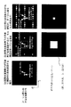
図2は、第1のレンズ31の後側焦点位置(=空間光変調素子2の位相および/または振幅分布に対するフーリエ面)における光の分布と、それに対応する遮光手段4の遮光パターンの一例を示す図である。なお、図2では、望ましい光の分布として、X方向に傾斜した平面波を考えた場合について示している。
【0055】
図2(a)は空間光変調素子2が完全に理想的に位相変調する場合、図2(b)は空間光変調素子2が理想的に位相変調するが、セル構造を持っている場合、図2(c)は空間光変調素子2の位相変調が不十分な場合(セル構造あり)について、それぞれ示している。
【0056】
ここで、図2(a)に示すように、空間光変調素子2が完全に理想的に位相変調する場合には、望ましい光しか存在しないので、遮光の必要はない。
しかし、実際には、ほとんど全ての空間光変調素子2がセル構造を持つため、空間光変調素子2が理想的に位相および/または振幅変調しても、図2(b)に示すような周期的な回折光が発生する。
【0057】
この場合には、セル構造による回折成分の周期は、空間光変調素子2上の変調パターンに依存しないため、セル構造による回折成分の周期以下の大きさを持つた開ロサイズとなるような遮光パターンを用いればよい。
【0058】
すなわち、空間光変調素子2のセル構造から決まる光成分だけを透過させるような遮光パターンを用いればよい。
一方、空間光変調素子2の位相および/または振幅変調が不十分、あるいは誤差を伴なう場合(現存する空間光変調素子の多くはこれに当てはまる)には、図2(c)に示すように多くの回折光が現われる。
【0059】
しかし、フーリエ面においては、多くの場合、図示ように様々な回折光成分が分離するため、望ましい光の成分のみを通過させるように遮光手段4の遮光パターンを設定すれば、望ましい光の成分のみが得られ、望ましい干渉縞を感光材料5に記録することができる。
【0060】
すなわち、空間光変調素子2のセル構造、および上記コンピュータによる分布計算の結果から決まる光成分だけを透過させるように、遮光手段4の遮光パターンを設定すればよい。
【0061】
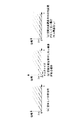
図3は、空間光変調素子2上の位相分布の一例(X方向に傾斜した平面波を作る場合)を示す図である。
図3(a)は望ましい位相分布、図3(b)は空間光変調素子2にセル構造がある場合の位相分布、図3(c)は空間光変調素子2の位相変調が正しくない場合(セル構造なし)について、それぞれ示している。
【0062】
上述したように、本実施の形態では、空間光変調素子2によってコンピュータで計算された位相および/または振幅の分布をレーザー光1Aに与えて物体光1A´とし、この物体光1A´の位相および/または振幅分布を結像系により結像して感光材料5に入射する際に、結像系内の変調された物体光1A´のフーリエ面に配置された所望の光成分だけを透過させる遮光手段4を透過させた後に、感光材料5に物体光1A´と可干渉性のある参照光1Bを入射させて干渉縞を記録するようにしているので、望ましい位相および/または振幅分布を持った物体光を感光材料5面に入射できるため、空間光変調素子2による位相および/または振幅変調が不十分であっても、望ましい干渉縞パターンを有するホログラムを精度良く作製することが可能となる。
【0063】
また、コンピュータ上での計算において搬送波を除外できるため、計算量が極めて少なく、短時間に計算が可能であり、かつデータ量も少なくすることが可能となる。
【0064】
さらに、レーザー光による露光プロセスにおいて、取り扱うデータ量が少なく、1回の露光である程度の大きさのホログラムが作製できるため、短時間に高精度なホログラムを簡便にして作製することが可能となる。
【0065】
一方、結像系として縮小結像系を用いているので、粗い解像度の空間光変調素子2を用いても、空間光変調素子2よりも高い解像度で物体光を表現することができ、十分細かい干渉縞パターンの変化を有するホログラムを作製することが可能となる。
【0066】
また、遮光手段4として、透過光の振幅(強度)分布を変調可能な空間光変調素子を用いているので、遮光領域を任意に変更できるため、必要な物体光1A´の成分のみを選択的に透過させることが可能となる。
【0067】
(第2の実施の形態)
図4は、本実施の形態によるホログラムの作製方法を実現するためのCGH作製装置の構成例を示す概要図であり、図1と同一部分には同一符号を付してその説明を省略し、ここでは異なる部分についてのみ述べる。
【0068】
すなわち、本実施の形態では、図4に示すように、図1における参照光1Bを、結像系の一部を構成する第2のレンズ32を通して、感光材料5面に入射させるようにしている。
【0069】
従って、本実施の形態においては、第2のレンズ32を通して参照光1Bを入射させることにより、第2のレンズ32の焦点距離f2 が短い場合でも容易に装置を構成することが可能となる等、装置のレンズ系等に対する選択の範囲が増え、縮小率の高い結像系も容易に実現でき、装置の小型化にも対応することができる。
【0070】
(第3の実施の形態)
本実施の形態では、前記第1または第2の実施の形態において、コンピュータによる分布計算の結果、空間光変調素子2による位相および/または振幅の分布の周波数成分が大きな幅を有する場合、位相および/または振幅の分布を複数の小さな周波数帯毎に振分けて分布を作成し、これら各周波数帯毎に干渉縞の記録を行ない、各周波数帯の全てを多重露光するようにしている。
【0071】
従って、本実施の形態においては、回折パターンがより複雑で望ましい光の成分とその他の成分が重なってしまう場合(空間光変調素子2による位相および/または振幅の分布の周波数成分が大きな幅を持つ揚合)に、空間光変調素子2の変調パターンを幾つかの周波数帯の変調パターンに分けて、一つの周波数帯の変調パターンを1回の露光に使用し、分けた周波数パターンの分だけ順次露光することにより、結果として感光材料5上に望ましい干渉縞パターンを得ることができる。
【0072】
すなわち、これは、空間光変調素子2の変調パターンの周波数がある程度の幅を持てば、フーリエ面では望ましい光の分布が広がりを持ち、空間光変調素子2の変調パターンの周波数が狭い範囲に限定されていれば、フーリエ面では望ましい光の分布が「点」状になることを利用しているものである。
【0073】
(第4の実施の形態)
本実施の形態では、前記第1または第2または第3の実施の形態において、感光材料5をX−Yステージ等に載置し、このX−Yステージ等を制御することで、感光材料5を感光材料面内で移動させるようにしている。
【0074】
従って、本実施の形態においては、感光材料をX−Yステージ等に載置し、X−Yステージ等を制御することで、感光材料5上の露光位置を適宜変えながら複数のホログラムを順次露光することにより、大きいサイズのホログラムを作製することも容易となる。
【0075】
【発明の効果】
以上説明したように、本発明のホログラムの作製方法および装置によれば、コンピュータ上での計算量を少なくし、短時間に高精度な任意の波面を再生するためのホログラムを簡便に作製することが可能であるのに加えて、さらに空間光変調素子による位相および/または振幅変調が不十分であっても、望ましい干渉縞パターンを有するホログラムを精度良く作製することが可能となる。
【図面の簡単な説明】
【図1】本発明の第1の実施の形態によるホログラムの作製方法を実現するためのCGH作製装置の構成例を示す概要図。
【図2】同第1の実施の形態における結像系内のフーリエ面における光の分布と、それに対応する遮光手段の遮光パターンの一例を示す図。
【図3】同第1の実施の形態における空間光変調素子2上の位相分布の一例(X方向に傾斜した平面波を作る場合)を示す図。
【図4】本発明の第2の実施の形態によるホログラムの作製方法を実現するためのCGH作製装置の構成例を示す概要図。
【符号の説明】
1A…レーザー光、
1A´…物体光、
1B…参照光、
2…空間光変調素子、
31…第1のレンズ、
32…第2のレンズ、
4…遮光手段、
5…感光材料。[0001]
BACKGROUND OF THE INVENTION
The present invention relates to a method and apparatus for producing a hologram for reproducing an arbitrary wavefront, and more particularly to a hologram having a desired interference fringe pattern even if phase and / or amplitude modulation by a spatial light modulator is insufficient. The present invention relates to a hologram manufacturing method and apparatus that can be manufactured with high accuracy.
[0002]
[Prior art]
In general, a hologram is an excellent medium for the purpose of reproducing an arbitrary wavefront. However, since a hologram obtained by photographing using normal laser light interference actually requires a subject or the like, the subject and the obtained hologram have their own limitations / limitations.
[0003]
On the other hand, a computer generated hologram (CGH) is a technique that can also produce a hologram that cannot actually be produced by laser light or the like in an interference manner. In other words, if a complex amplitude distribution on a hologram surface for reproducing a desired wavefront is calculated by a computer, and a device that physically realizes this is produced, the CGH is completed.
[0004]
By the way, as a method for producing such a CGH, conventionally, a calculated pattern is drawn by an XY plotter or the like, and the image is reduced to an appropriate size or has a high resolution. There is a method of directly drawing a pattern using an apparatus.
[0005]
However, in any of these methods, the amount of calculation in a computer is enormous, and therefore a long time is required and the amount of data to be handled is enormous. Also, since a large amount of data must be drawn when producing the data, a long processing time is required for this, and it is impossible to produce a CGH having a relatively large size.
[0006]
Therefore, recently, as a method for solving such a problem, for example, a method for producing a hologram as shown in “Japanese Patent Application No. 6-105694” has been proposed.
[0007]
That is, this hologram manufacturing method generates a distribution of the phase or phase / amplitude (hereinafter referred to as phase and / or amplitude) of the object light by the spatial light modulation element, and simultaneously reduces the image of the object light and simultaneously generates the reference light. The interference fringes are recorded by causing interference.
[0008]
[Problems to be solved by the invention]
However, in such a method, generally, when phase and / or amplitude modulation is performed using a liquid crystal display device or the like as the spatial light modulation element, the phase and / or amplitude distribution of the object light is adjusted by the spatial light modulation element. It is very difficult to modulate accurately, and it is difficult to accurately produce a hologram having a desired interference fringe pattern.
[0009]
An object of the present invention is to reduce the amount of calculation on a computer, to easily produce a hologram for reproducing an arbitrary wavefront with high accuracy in a short time, and to further provide a phase and / or a spatial light modulation element. An object of the present invention is to provide a hologram manufacturing method and apparatus capable of accurately manufacturing a hologram having a desired interference fringe pattern even when amplitude modulation is insufficient.
[0010]
[Means for Solving the Problems]
In order to achieve the above object, according to the first aspect of the present invention, in the method for producing a hologram for reproducing an arbitrary wavefront, the phase and / or amplitude of the desired reproduction wavefront on the hologram surface is calculated by a computer. The distribution is calculated, and the phase and / or amplitude distribution calculated by the computer is applied to the laser light by the spatial light modulation element as object light, and the phase of the object light by the spatial light modulation element and / or by the imaging system The amplitude distribution is imaged while passing through a light-shielding means that transmits only the desired light component disposed in the vicinity of the Fourier plane of the modulated object light in the imaging system and is incident on the photosensitive material for hologram recording. In this way, the reference light having coherence with the object light is incident on the photosensitive material, and interference fringes are recorded by the interference between the two.If the frequency component of the phase and / or amplitude distribution by the spatial light modulation element has a large width as a result of the distribution calculation by the computer, the distribution is created by distributing the phase and / or amplitude distribution into a plurality of small frequency bands. In addition, interference fringes are recorded for each frequency band so that all of each frequency band is subjected to multiple exposure.ing.
[0011]
Here, in particular, as the light shielding means, for example, as described in
[0012]
Further, as the light shielding means, it is preferable to transmit only the 0th-order diffracted light component determined from the cell structure of the spatial light modulator, for example, as described in claim 3.
Further, as the light shielding means, for example, as described in claim 4, it is preferable that only the light component determined from the cell structure of the spatial light modulator and the result of the distribution calculation by the computer is transmitted.
[0013]
Therefore, in the hologram manufacturing method according to the first to fourth aspects of the present invention, the phase and / or amplitude distribution on the hologram surface relating to a desired reproduction wavefront is calculated by a computer, and the phase and the amplitude are calculated by a spatial light modulator. When the distribution of amplitude is given to the laser beam as object light, and the phase and / or amplitude distribution of the object light is imaged by the imaging system and incident on the photosensitive material, it is modulated in the imaging system. By passing through a light shielding means that transmits only a desired light component arranged in the vicinity of the Fourier plane of the object light, and then recording the interference fringes by causing the object light and coherent reference light to enter the photosensitive material. Since object light having a desired phase and / or amplitude distribution can be incident on the surface of the photosensitive material, even if phase and / or amplitude modulation by the spatial light modulator is insufficient, A hologram having a preferable interference fringe patterns can be accurately manufactured.In the method for producing a hologram of claim 1, the modulation pattern of the spatial light modulator is divided into modulation patterns of several frequency bands, and the modulation pattern of one frequency band is used for one exposure, Undesired object light components for each frequency pattern are shielded by the light shielding means and sequentially exposed by the divided frequency patterns, so that a desired interference fringe pattern can be obtained on the photosensitive material.
[0014]
Further, since the carrier wave can be excluded in the calculation on the computer, the calculation amount is extremely small, the calculation can be performed in a short time, and the data amount can be reduced.
[0015]
Furthermore, in the exposure process using laser light, the amount of data handled is small, and a hologram having a certain size can be produced by one exposure, so that a highly accurate hologram can be easily produced in a short time.
[0016]
On the other hand, in the fifth aspect of the invention, in the hologram manufacturing method according to any one of the first to fourth aspects, a reduced image forming system is used as the image forming system.
[0017]
Therefore, in the hologram manufacturing method according to the fifth aspect of the invention, by using the reduced imaging system as the imaging system, the object light can be expressed with a high resolution even if a spatial light modulation element with a coarse resolution is used. And a hologram having a sufficiently fine interference fringe pattern change can be produced.
[0018]
According to a sixth aspect of the invention, in the hologram manufacturing method according to any one of the first to fifth aspects, a spatial light modulation element capable of modulating the amplitude distribution of transmitted light is used as the light shielding means. I am doing so.
[0019]
Therefore, in the hologram manufacturing method according to the sixth aspect of the present invention, the light shielding region can be arbitrarily changed by using a spatial light modulation element capable of modulating the amplitude (intensity) distribution of transmitted light as the light shielding means. Only the object light component can be selectively transmitted. That is, object light can be optimized in each hologram obtained by one exposure.
[0020]
Further, in the seventh aspect of the present invention, in the hologram manufacturing method according to any one of the first to sixth aspects, the reference light is incident through the imaging system.
[0021]
Therefore, in the hologram manufacturing method according to the seventh aspect of the invention, the range of selection with respect to the lens system of the apparatus is increased, for example, a lens having a short focal length can be used by making the reference light incident through the imaging system. It is possible to cope with downsizing of the apparatus.
[0022]
According to an eighth aspect of the present invention, in the hologram manufacturing method according to any one of the first to seventh aspects, the photosensitive material is moved within the surface of the photosensitive material.
[0023]
Therefore, in the method for producing a hologram according to the eighth aspect of the invention, it is possible to perform exposure while appropriately changing the exposure position on the photosensitive material by moving the photosensitive material within the surface of the photosensitive material. It is also easy to produce a hologram.
[0028]
DETAILED DESCRIPTION OF THE INVENTION
According to the present invention, in the conventional hologram manufacturing method described above, a light shielding means (variable aperture means) that transmits only a desired light component is disposed near the Fourier plane of the object light in the imaging system with respect to the spatial light modulator. This makes it possible to record a desired interference fringe even if the phase and / or amplitude of the object light is not sufficiently modulated by the spatial light modulator.
[0029]
Hereinafter, embodiments of the present invention based on the above-described concept will be described in detail with reference to the drawings.
(First embodiment)
FIG. 1 is a schematic diagram showing a configuration example of a CGH manufacturing apparatus for realizing the hologram manufacturing method according to the present embodiment.
[0030]
That is, as shown in FIG. 1, the CGH manufacturing apparatus according to the present embodiment gives the
[0031]
Here, the light blocking means 4 is preferably arranged on the Fourier plane of the phase and / or amplitude distribution of the spatial
Further, as the light shielding means 4, only the light component determined from the cell structure of the spatial
[0032]
Furthermore, it is preferable to use a spatial light modulation element (for example, a liquid crystal display device) that can modulate the amplitude (intensity) distribution of transmitted light as the light shielding means 4.
On the other hand, it is preferable to use a reduced imaging system as the imaging system. That is, for reduction image formation, for example, a lens having a focal length f2 shorter than the focal length f1 of the first lens 31 may be used as the
[0033]
Further, it is preferable to use a liquid crystal display device as the spatial
Next, a method for manufacturing a hologram using the CGH manufacturing apparatus of the present embodiment configured as described above will be described.
[0034]
In the present embodiment, a hologram is produced by the following method.
That is, as shown in FIG. 1, first, a phase and / or amplitude distribution on a hologram surface for forming a desired reproduction wavefront is calculated by a computer (not shown).
[0035]
Next, laser light emitted from a laser light source (not shown) is divided into two, and one of the
[0036]
The
[0037]
At this time, the spatial light modulation element 3 performs phase and / or amplitude modulation for forming a desired reproduction wavefront calculated by the computer, and this reproduction wavefront does not include any consideration regarding the carrier wave.
[0038]
Thereafter, the magnification in the direction orthogonal to the incident direction of the
[0039]
Here, when the phase and / or amplitude distribution of the
[0040]
As a result, the object beam (laser beam) 1A ′ and the coherent reference beam (
[0041]
Then, the hologram recorded in this way can be obtained with a desired reproduction wavefront by applying appropriate illumination light after processing such as development as necessary.
[0042]
An arbitrary wavefront can be applied as the reproduction wavefront in the present embodiment. For example, it is possible to display a three-dimensional object that does not exist or cannot be obtained by a normal method even if it exists, or an optical element or the like. Easy to do.
[0043]
Next, in the hologram manufacturing method according to the present embodiment as described above, the
[0044]
Here, the imaging system has a function of imaging the phase and / or amplitude distribution of the spatial
[0045]
For this reason, since the carrier wave can be excluded in the calculation on the computer, the calculation amount is extremely small, the calculation is possible in a short time, and the data amount (there is a data amount more than twice the frequency of the interference fringes). Can be reduced. In addition, in the exposure process using laser light, the amount of data to be handled is small, and a hologram having a certain size can be produced by one exposure. Therefore, a highly accurate hologram can be easily produced in a short time. Further, when the imaging system has a reduced imaging function, even if the spatial
[0046]
That is, the carrier wave is necessary for separating the reproduction wavefront reproduced by the produced hologram and the illumination light incident for reproduction. Generally, the carrier wave has a higher frequency than the phase / amplitude distribution that forms the reproduction wavefront on the hologram surface, and therefore the carrier wave requires a huge amount of data and high resolution in the hologram. In this embodiment using laser beam interference, the carrier wave is replaced with a phase and / or amplitude distribution on the photosensitive material 5 depending on the incident angle of the
[0047]
Therefore, in this embodiment, only the phase and / or amplitude distribution of the reproduction wavefront that requires a relatively coarse resolution needs to be processed, so that the amount of data is small, the calculation is short, and the space with a relatively coarse resolution is used. Even if the
[0048]
Here, in general, it is difficult to accurately perform the phase and / or amplitude modulation by the spatial
[0049]
At this time, even if the phase and / or amplitude modulation by the spatial
[0050]
The distribution of light at the rear focal position of the first lens 31 of the diffracted light component generated due to inaccurate phase and / or amplitude modulation and the light component corresponding to the desired phase and / or amplitude modulation is respectively spatial light Depending on the phase and / or amplitude pattern modulated by the
[0051]
That is, in order to extract the light component corresponding to the desired phase and / or amplitude modulation more precisely, it is necessary to change the light shielding pattern in the light shielding means 4 arranged at the rear focal position of the first lens 31 each time. .
[0052]
Therefore, it is preferable to use a spatial light modulation element capable of modulating the intensity (amplitude) distribution of transmitted light as the light shielding means 4.
In the case as described above, the light distribution at the rear focal position of the first lens 31 has a relationship of the Fourier transform with the phase and / or amplitude distribution of the spatial
[0053]
Accordingly, the light distribution at the rear focal position of the first lens 31 can be easily calculated using a computer, and the distribution of the desired light component can be easily grasped. can do.
[0054]
FIG. 2 shows an example of the light distribution at the rear focal position of the first lens 31 (= Fourier plane for the phase and / or amplitude distribution of the spatial light modulator 2) and the corresponding light shielding pattern of the light shielding means 4. FIG. FIG. 2 shows a case where a plane wave inclined in the X direction is considered as a desirable light distribution.
[0055]
FIG. 2A shows a case where the spatial
[0056]
Here, as shown in FIG. 2A, in the case where the spatial
However, in practice, almost all of the spatial
[0057]
In this case, since the period of the diffraction component due to the cell structure does not depend on the modulation pattern on the spatial
[0058]
That is, a light shielding pattern that transmits only the light component determined by the cell structure of the spatial
On the other hand, when the phase and / or amplitude modulation of the spatial
[0059]
However, in the Fourier plane, in many cases, various diffracted light components are separated as shown in the figure. Therefore, if the light shielding pattern of the light shielding means 4 is set so that only the desired light components pass, only the desired light components are obtained. The desired interference fringes can be recorded on the photosensitive material 5.
[0060]
That is, the light shielding pattern of the light shielding means 4 may be set so that only the light component determined from the cell structure of the spatial
[0061]
FIG. 3 is a diagram illustrating an example of a phase distribution on the spatial light modulator 2 (in the case of creating a plane wave inclined in the X direction).
3A is a desirable phase distribution, FIG. 3B is a phase distribution when the spatial
[0062]
As described above, in the present embodiment, the phase and / or amplitude distribution calculated by the spatial
[0063]
Further, since the carrier wave can be excluded in the calculation on the computer, the calculation amount is extremely small, the calculation can be performed in a short time, and the data amount can be reduced.
[0064]
Furthermore, in the exposure process using laser light, the amount of data handled is small, and a hologram having a certain size can be produced by one exposure. Therefore, a highly accurate hologram can be easily produced in a short time.
[0065]
On the other hand, since the reduced imaging system is used as the imaging system, the object light can be expressed with a higher resolution than that of the spatial
[0066]
Further, since a spatial light modulation element capable of modulating the amplitude (intensity) distribution of transmitted light is used as the light shielding means 4, the light shielding region can be arbitrarily changed, so that only the necessary component of the
[0067]
(Second Embodiment)
FIG. 4 is a schematic diagram showing a configuration example of a CGH production apparatus for realizing the hologram production method according to the present embodiment, where the same parts as those in FIG. Only the different parts are described here.
[0068]
That is, in the present embodiment, as shown in FIG. 4, the
[0069]
Therefore, in the present embodiment, by making the
[0070]
(Third embodiment)
In the present embodiment, in the first or second embodiment, as a result of the distribution calculation by the computer, when the frequency component of the phase and / or amplitude distribution by the spatial
[0071]
Therefore, in the present embodiment, when the diffraction pattern is more complicated and the desired light component overlaps with other components (the frequency component of the phase and / or amplitude distribution by the spatial
[0072]
That is, if the frequency of the modulation pattern of the spatial
[0073]
(Fourth embodiment)
In the present embodiment, in the first, second or third embodiment, the photosensitive material 5 is placed on an XY stage or the like, and the XY stage or the like is controlled, whereby the photosensitive material 5 is controlled. Is moved within the surface of the photosensitive material.
[0074]
Therefore, in this embodiment, a plurality of holograms are sequentially exposed while appropriately changing the exposure position on the photosensitive material 5 by placing the photosensitive material on an XY stage or the like and controlling the XY stage or the like. By doing so, it becomes easy to produce a large-size hologram.
[0075]
【The invention's effect】
As described above, according to the method and apparatus for producing a hologram of the present invention, it is possible to easily produce a hologram for reproducing an arbitrary wavefront with high accuracy in a short time with a small amount of calculation on a computer. In addition, it is possible to accurately produce a hologram having a desired interference fringe pattern even if the phase and / or amplitude modulation by the spatial light modulator is insufficient.
[Brief description of the drawings]
FIG. 1 is a schematic diagram showing a configuration example of a CGH manufacturing apparatus for realizing a hologram manufacturing method according to a first embodiment of the present invention.
FIG. 2 is a diagram showing an example of a light distribution on a Fourier plane in the imaging system according to the first embodiment and a light shielding pattern of a light shielding unit corresponding thereto.
FIG. 3 is a view showing an example of a phase distribution on the spatial
FIG. 4 is a schematic diagram showing a configuration example of a CGH production apparatus for realizing a hologram production method according to a second embodiment of the present invention.
[Explanation of symbols]
1A ... Laser light,
1A '... object light,
1B: Reference light,
2 ... Spatial light modulator,
31 ... first lens,
32 ... second lens,
4 ... light shielding means,
5: Photosensitive material.
Claims (10)
コンピュータにより、所望の再生波面に関するホログラム面上での位相および/または振幅の分布を計算し、
空間光変調素子により、前記コンピュータで計算された位相および/または振幅の分布をレーザー光に与えて物体光とし、
結像系により、前記空間光変調素子による物体光の位相および/または振幅の分布を、前記結像系内の前記変調された物体光のフーリエ面付近に配置された所望の光成分だけを透過させる遮光手段を透過させつつ結像してホログラム記録用の感光材料に入射させ、前記感光材料に、前記物体光と可干渉性のある参照光を入射させて両者の干渉により干渉縞を記録するようにし、
前記コンピュータによる分布計算の結果、前記空間光変調素子による位相および/または振幅の分布の周波数成分が大きな幅を有する場合、前記位相および/または振幅の分布を複数の小さな周波数帯毎に振分けて分布を作成し、
前記各周波数帯毎に前記干渉縞の記録を行ない、
前記各周波数帯の全てを多重露光するようにした
ことを特徴とするホログラムの作製方法。In a method for producing a hologram for reproducing an arbitrary wavefront,
The computer calculates the phase and / or amplitude distribution on the hologram surface for the desired reproduction wavefront,
The spatial light modulation element gives the laser light a distribution of phase and / or amplitude calculated by the computer as object light,
By the imaging system, the phase and / or amplitude distribution of the object light by the spatial light modulator is transmitted only through a desired light component disposed in the vicinity of the Fourier plane of the modulated object light in the imaging system. An image is formed while being transmitted through the light shielding means to be incident on a photosensitive material for hologram recording, and the object light and coherent reference light are incident on the photosensitive material, and interference fringes are recorded by interference between the two. the way,
As a result of the distribution calculation by the computer, when the frequency component of the phase and / or amplitude distribution by the spatial light modulator has a large width, the distribution of the phase and / or amplitude is distributed for each of a plurality of small frequency bands. Create
Recording the interference fringes for each frequency band,
A method for producing a hologram, wherein multiple exposure is performed on all the frequency bands .
前記遮光手段としては、前記結像系内における空間光変調素子の位相および/または振幅の分布のフーリエ面に配置するようにした
ことを特徴とするホログラムの作製方法。In the method for producing a hologram according to claim 1,
A method for producing a hologram, wherein the light shielding means is arranged on a Fourier plane of a phase and / or amplitude distribution of a spatial light modulator in the imaging system.
前記遮光手段としては、前記空間光変調素子のセル構造から決まる0次回折光成分だけを透過させるようにした
ことを特徴とするホログラムの作製方法。In the method for producing a hologram according to claim 1,
The method for producing a hologram characterized in that the light shielding means transmits only the 0th-order diffracted light component determined from the cell structure of the spatial light modulator.
前記遮光手段としては、前記空間光変調素子のセル構造、および前記コンピュータによる分布計算の結果から決まる光成分だけを透過させるようにした
ことを特徴とするホログラムの作製方法。In the method for producing a hologram according to claim 1,
A method for producing a hologram, wherein as the light shielding means, only a light component determined from a cell structure of the spatial light modulator and a distribution calculation result by the computer is transmitted.
前記結像系としては、縮小結像系を用いるようにした
ことを特徴とするホログラムの作製方法。In the method for producing a hologram according to any one of claims 1 to 4,
A method for producing a hologram, wherein a reduced imaging system is used as the imaging system.
前記遮光手段としては、透過光の振幅分布を変調可能な空間光変調素子を用いるようにした
ことを特徴とするホログラムの作製方法。The method for producing a hologram according to any one of claims 1 to 5,
As the light shielding means, a spatial light modulator capable of modulating the amplitude distribution of transmitted light is used.
前記参照光を、前記結像系を通して入射させるようにした
ことを特徴とするホログラムの作製方法。In the method for producing a hologram according to any one of claims 1 to 6,
A method for producing a hologram, wherein the reference light is incident through the imaging system.
前記感光材料を、感光材料面内で移動させるようにした
ことを特徴とするホログラムの作製方法。In the method for producing a hologram according to any one of claims 1 to 7,
A method for producing a hologram, wherein the photosensitive material is moved in the plane of the photosensitive material.
前記空間光変調素子としては、液晶表示デバイスを用いるようにした
ことを特徴とするホログラムの作製方法。In the method for producing a hologram according to any one of claims 1 to 8,
A liquid crystal display device is used as the spatial light modulation element. A method for manufacturing a hologram, wherein:
前記遮光手段としては、液晶表示デバイスを用いるようにした
ことを特徴とするホログラムの作製方法。In the method for producing a hologram according to any one of claims 1 to 9,
A liquid crystal display device is used as the light-shielding means.
Priority Applications (1)
| Application Number | Priority Date | Filing Date | Title |
|---|---|---|---|
| JP21745798A JP4199332B2 (en) | 1998-07-31 | 1998-07-31 | Method for producing hologram |
Applications Claiming Priority (1)
| Application Number | Priority Date | Filing Date | Title |
|---|---|---|---|
| JP21745798A JP4199332B2 (en) | 1998-07-31 | 1998-07-31 | Method for producing hologram |
Publications (2)
| Publication Number | Publication Date |
|---|---|
| JP2000047553A JP2000047553A (en) | 2000-02-18 |
| JP4199332B2 true JP4199332B2 (en) | 2008-12-17 |
Family
ID=16704539
Family Applications (1)
| Application Number | Title | Priority Date | Filing Date |
|---|---|---|---|
| JP21745798A Expired - Fee Related JP4199332B2 (en) | 1998-07-31 | 1998-07-31 | Method for producing hologram |
Country Status (1)
| Country | Link |
|---|---|
| JP (1) | JP4199332B2 (en) |
Families Citing this family (8)
| Publication number | Priority date | Publication date | Assignee | Title |
|---|---|---|---|---|
| JP3881865B2 (en) | 2001-10-19 | 2007-02-14 | 株式会社 液晶先端技術開発センター | Optical recording apparatus and method, and exposure apparatus and method |
| JP2006276666A (en) * | 2005-03-30 | 2006-10-12 | Fujitsu Ltd | Hologram recorder |
| EP1873765A1 (en) * | 2006-06-27 | 2008-01-02 | Deutsche Thomson-Brandt Gmbh | Holographic storage system based on common path interferometry |
| CN103513557B (en) * | 2013-10-12 | 2016-01-13 | 北京工业大学 | A kind of coaxial digital holography phase retrieval formation method of continuous THz wave |
| CN104111257A (en) * | 2014-07-24 | 2014-10-22 | 江苏大学 | System and method for phase micro-interference imaging based on common-optical path system |
| JP6614636B2 (en) * | 2015-05-08 | 2019-12-04 | 国立研究開発法人情報通信研究機構 | Method for manufacturing hologram screen |
| JP6607491B2 (en) * | 2015-10-27 | 2019-11-20 | 国立研究開発法人情報通信研究機構 | Hologram data generation device and program thereof |
| CN105676498B (en) * | 2016-03-23 | 2018-09-28 | 北京航空航天大学 | The amplitude modulation method and device of pure phase type spatial light modulator |
-
1998
- 1998-07-31 JP JP21745798A patent/JP4199332B2/en not_active Expired - Fee Related
Also Published As
| Publication number | Publication date |
|---|---|
| JP2000047553A (en) | 2000-02-18 |
Similar Documents
| Publication | Publication Date | Title |
|---|---|---|
| US20150147685A1 (en) | System and method for holography-based fabrication | |
| TW478032B (en) | Method and device for laser plotting, hologram master and the manufacturing method thereof | |
| JP4022398B2 (en) | Method and apparatus for creating phase shift mask | |
| JP4199332B2 (en) | Method for producing hologram | |
| US20170212472A1 (en) | System and method for holography-based fabrication | |
| CN107065488A (en) | The laser hologram direct printer and method of a kind of use frequency domain filtering | |
| JPH05505032A (en) | Manufacture of flat panel displays | |
| CN104749890B (en) | Exposure method and system of photoetching technology | |
| JP3872124B2 (en) | Hologram creation device, hologram display device, holography system, hologram creation method, and hologram display method | |
| JP4232253B2 (en) | Fine pattern manufacturing apparatus and holographic memory recording / reproducing apparatus | |
| JP3593359B2 (en) | Hologram fabrication method | |
| JP3713812B2 (en) | Diffraction grating pattern manufacturing device | |
| JP4045390B2 (en) | Optical recording method, optical recording apparatus, and optical reproducing method | |
| JPH05505031A (en) | How to manufacture optical discs | |
| Yamaguchi et al. | Development of a Fringe Printer With 0.35 μm Pixel Pitch | |
| JPH03100514A (en) | Generating method for hologram | |
| Matsushima et al. | Fabrication of High-Definition CGH | |
| EP1876591A2 (en) | Hologram recording device, hologram reproducing device and hologram recording method not requiring positioning of a phase mask | |
| JP3673959B2 (en) | Method for producing hologram | |
| JP5062423B2 (en) | Method for producing volume hologram and volume hologram produced by the method | |
| JP4475031B2 (en) | Hologram recording apparatus, hologram reproducing apparatus, and information processing apparatus | |
| JP3420802B2 (en) | Holographic stereogram | |
| JP3355722B2 (en) | How to create a diffraction grating pattern | |
| JPS624681B2 (en) | ||
| JP2806927B2 (en) | Hologram reproducing method and reproducing apparatus |
Legal Events
| Date | Code | Title | Description |
|---|---|---|---|
| A621 | Written request for application examination |
Free format text: JAPANESE INTERMEDIATE CODE: A621 Effective date: 20050621 |
|
| A977 | Report on retrieval |
Free format text: JAPANESE INTERMEDIATE CODE: A971007 Effective date: 20080116 |
|
| A131 | Notification of reasons for refusal |
Free format text: JAPANESE INTERMEDIATE CODE: A131 Effective date: 20080325 |
|
| A521 | Written amendment |
Free format text: JAPANESE INTERMEDIATE CODE: A523 Effective date: 20080523 |
|
| A521 | Written amendment |
Free format text: JAPANESE INTERMEDIATE CODE: A523 Effective date: 20080603 |
|
| TRDD | Decision of grant or rejection written | ||
| A01 | Written decision to grant a patent or to grant a registration (utility model) |
Free format text: JAPANESE INTERMEDIATE CODE: A01 Effective date: 20080930 |
|
| A01 | Written decision to grant a patent or to grant a registration (utility model) |
Free format text: JAPANESE INTERMEDIATE CODE: A01 |
|
| A61 | First payment of annual fees (during grant procedure) |
Free format text: JAPANESE INTERMEDIATE CODE: A61 Effective date: 20081003 |
|
| FPAY | Renewal fee payment (event date is renewal date of database) |
Free format text: PAYMENT UNTIL: 20111010 Year of fee payment: 3 |
|
| R150 | Certificate of patent or registration of utility model |
Free format text: JAPANESE INTERMEDIATE CODE: R150 |
|
| FPAY | Renewal fee payment (event date is renewal date of database) |
Free format text: PAYMENT UNTIL: 20111010 Year of fee payment: 3 |
|
| FPAY | Renewal fee payment (event date is renewal date of database) |
Free format text: PAYMENT UNTIL: 20121010 Year of fee payment: 4 |
|
| FPAY | Renewal fee payment (event date is renewal date of database) |
Free format text: PAYMENT UNTIL: 20131010 Year of fee payment: 5 |
|
| LAPS | Cancellation because of no payment of annual fees |