【0001】
【発明の属する技術分野】
本発明は、コンピュータで作成した画像やスキャナ等でコンピュータに入力した画像を空間光変調素子やシャッターを用いることなく、マスターホログラムと未露光感光材料を重ねた上にレンズ、鏡、ガルバノメータースキャナーで構成された光路を通ったレーザービームにより直接露光を行う装置により、極めて短時間な露光が可能で、特に振動の影響を受けにくく、極めて微細な線幅を有するホログラム画線を作製することが可能となるホログラムの作製方法に関するものである。
【0002】
【従来の技術】
従来から、ホログラムを作製する方法の一つとして計算機を用いて自動的に立体的な画像のホログラムを作製する方法が提案されている。この方法は、特開昭63−131167号公報、特開平2−259684号公報、特開平2−259685号公報、特開平5−35171号公報、特開平6−59613号公報、特開平6−59614号公報などで周知されている。しかし、例えば、前記特開平5−35171号公報には、「感光材料をX−Yステージに載置し、画像データに従ってその対応する位置に前記X−Yステージを順次移動させながらレーザービームを入射させる」、また、特開平6−59613号公報には、「マスターホログラムの上に、各セルが前記各要素ホログラムに対応した空間光変調素子を配置して、当該空間光変調素子により視差画像データに従ってその対応位置の透過光の強弱を制御し、前記空間光変調素子の面からレーザー光を入射させて、透過型のホログラムを作製する」と記載されているように、これらの方法ではホログラムの作製に時間がかかるばかりでなく、安定したホログラムを作製できないという問題があり、改善が図られてきたが完全には解決されていなかった。
【0003】
【発明が解決しようとする課題】
以上のように、従来のホログラムの作製方法においては、ホログラムの作製に時間がかかり、安定したホログラムを作製することができなかった。さらに従来のホログラムの作製方法は、ドットを画素としてホログラムを作製するために、連続的に線幅の変化するホログラムまたは線毎に線幅を変化させたホログラムの作製は困難であった。
【0004】
【課題を解決するための手段】
上記の目的を達成するため、未露光感光材料上に、拡散板を記録し回折格子として作用するマスターホログラムを重ね合わせ、前記重ね合わせた上面に、複数のレンズと、鏡と、2台のガルバノメータースキャナーとで構成される光学系によりレーザービームを入射させ、前記入射したレーザービームは、マスターホログラム面で回折光と透過光に分光し、前記未露光感光材料の面に、干渉縞を記録することを特徴とするホログラムの作製装置を用いたホログラムの作製方法において、前記レーザービームが感光材料の感光面で焦点を結び、レーザービームによる露光量を変化させることにより連続的に線幅の異なるホログラム、または、線幅を変化させたホログラムを作製するホログラムの作製方法である。
【0005】
また、前記ホログラムの作製装置において、未露光感光材料とマスターホログラムの重ね方を反対にすることにより干渉縞の方向が異なって記録されるようにし、レーザービームが感光材料の感光面で焦点を結び、レーザービームによる露光量を変化させることにより連続的に線幅の異なるホログラム、または、線幅を変化させたホログラムを作製するホログラムの作製方法である。
【0006】
さらに、前記ホログラムの作製装置において、1枚の未露光感光材料に対し、回折方向の異なるマスターホログラムを複数枚用いることにより、多方向に回折するホログラムを作製するようにして、レーザービームが感光材料の感光面で焦点を結び、レーザービームによる露光量を変化させることにより連続的に線幅の異なるホログラム、または、線幅を変化させたホログラムを作製するホログラムの作製方法である。
【0007】
さらに、前記ホログラムの作製装置において、ガルバノメータースキャナをコンピューター制御することにより、シャッターを用いることなく任意の位置に干渉縞を記録するホログラムを作製するホログラムの作製方法である。
【0008】
さらに、前記ホログラムの作製装置において、ガルバノメータースキャナによるレーザービームの走査速度の変化、レーザーの電源電流の制御、偏光フィルムを光学系に挿入、マイクロミラーを光学系に挿入、機械的絞り装置を光学系に挿入またはLCDを光学系に挿入することにより、レーザービームによる露光量を変化させることによってホログラムを作製するホログラムの作製方法である。
【0009】
【発明の実施の形態】
本発明は、図1に示す干渉縞記録装置により、レーザービームが感光材料の感光面で焦点を結び、レーザービームによる露光量を変化させることにより連続的に線幅の異なるホログラム、または、線幅を変化させたホログラムを作製した。
【0010】
【実施例】
以下、本発明の実施例について図面を参照して詳細に説明する。ここでは透過型ホログラムの作製方法について説明する。
【0011】
(実施例1)図1は、本発明のホログラムを作製するホログラム作製装置の概略図である。まず、図1の感光材料(1)上に拡散板を記録したマスターホログラム(2)を重ね、複数のレンズ(4)、(5)と、ミラー(図示せず)と、2台のガルバノメータースキャナ(6)、(7)を用い、図示しない別のガルバノメータースキャナのドライバにより、レーザービームを走査させて露光を行う。ここで用いるガルバノメータースキャナは、軸に取り付けられたミラーを回転方向に振動させることで、レーザービームを1次元空間に走査させることができる。また、このガルバノメータースキャナを2台直角に配置して用いることにより、レーザービームを2次元空間に走査することができる。
【0012】
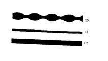
図2は、マスターホログラムにレーザービームが入射した時の様子を模式的に示した説明図であり、マスターホログラム(10)と感光材料(9)の間隔が開いているが、これは説明のためであり実際には密着した状態になっている。入射したレーザービーム(11)はマスターホログラム(10)により透過光(12)及び回折光(13)に分光する。マスターホログラム(10)直下ではそれらのレーザービームが重なっており(14)、そこに感光材料を置くことにより干渉縞を記録できる。その結果、マスターホログラムの複写体が形成される。また、ここで、感光材料(9)の感光材料塗布面で、レンズ(4)、(5)によりレーザービームの焦点を結ぶようにすることで、焦点位置のスポット径の幅を持つ微細な画線が作製される。このホログラム作製装置において、露光量を変化させることで、図3に示すような、1本の画線の線幅が連続的に変化するホログラム(15)や、線幅の異なる画線のホログラム(16)、(17)が作製できる。
【0013】
(実施例2)次に、レーザービームの露光量を変化させてホログラムを作製する方法を詳述する。本実施例における、それぞれの露光量を変化させる素子の光学系中での位置は一例であり、他の部位でも同様の効果が得られる。
【0014】
まず、図1に示すように、レーザービームの光量を一定にし、ガルバノメータースキャナ(6)、(7)の走査速度を変化させる。レーザービームの断面はガウス分布状に光量が変化しているため、中心が最も光量が多く、外側になるにつれて少なくなる。そのため、ガルバノメータースキャナの走査速度が速い時は、レーザービームの中心付近のみ露光されることになる。また、ガルバノメータースキャナの走査速度が遅い時は、レーザービームの外側も適正露光量となり露光される。このガルバノメータースキャナの走査速度を画線毎に変化させると、線幅の異なる画線のホログラムを作製することができ、また、ガルバノメータースキャナの走査速度を画線の露光中に変化させると、1本の画線中に線幅が連続的に変化するホログラムを作製することができる。
【0015】
他の方法としては、図1に示すように、ガルバノメータースキャナの走査速度を一定にし、レーザーの電源電流(3)を制御することによりレーザービームの光量を変化させる。レーザービームの断面はガウス分布状に光量が変化しているため、中心が最も光量が多く、外側になるにつれて少なくなる。そのため、全体の光量が少ない時は、レーザーヒームの中心付近のみ露光されることになる。また、全体の光量が多い時は、レーザービームの外側も適正露光量となり露光される。このレーザーの電源電流を画線毎に変化させると、線幅の異なる画線のホログラムを作製することができ、また、レーザーの電源電流を画線の露光中に変化させると、1本の画線中に線幅が連続的に変化するホログラムを作製することができる。
【0016】
他の方法としては、図4に示すように、レーザービームの光量及びガルバノメータースキャナの走査速度を一定にした上で、光学系に偏光フィルム(21)を挿入し回転させ光量を変化させる。レーザービームの断面はガウス分布状に光量が変化しているため、中心が最も光量が多く、外側になるにつれて少なくなる。そのため、偏光フィルムにより光量が少ない時は、レーザービームの中心付近のみ露光されることになる。また、偏光フィルムにより光量が多い時は、レーザービームの外側も適正露光量となり露光される。この偏光フィルムの回転による光量の変化を画線毎に変化させると、線幅の異なる画線のホログラムを作製することができ、また、偏光フィルムの回転による光量の変化を画線の露光中に変化させると、1本の画線中に線幅が連続的に変化するホログラムを作製することができる。
【0017】
他の方法としては、図5に示すように、レーザービームの光量及びガルバノメータースキャナの走査速度を一定にした上で、光学系にマイクロミラー(31)を挿入し制御させ、レーザービーム径を変化させる。このマイクロミラーの制御によるレーザービーム径の変化を画線毎に変化させると、線幅の異なる画線のホログラムを作製することができ、また、マイクロミラーの制御によるレーザービーム径の変化を画線の露光中に変化させると、1本の画線中に線幅が連続的に変化するホログラムを作製することができる。
【0018】
他の方法としては、図6に示すように、レーザービームの光量及びガルバノメータースキャナの走査速度を一定にした上で、光学系に機械的絞り装置(40)を挿入し制御させレーザービーム径を変化させる。この機械的絞り装置の制御によるレーザービーム径の変化を画線毎に変化させると、線幅の異なる画線のホログラムを作製することができ、また、機械的絞り装置の制御によるレーザービーム径の変化を画線の露光中に変化させると、1本の画線毎に線幅が連続的に変化するホログラムを作製することができる。
【0019】
他の方法としては、図6に示すように、レーザービームの光量及びガルバノメータースキャナの走査速度を一定にした上で、光学系にLCD(41)を挿入し制御させレーザービーム径を変化させる。このLCDの制御によるレーザービーム径の変化を画線毎に変化させると、線幅の異なる画線のホログラムを作製することができ、また、LCDの制御によるレーザービーム径の変化を画線の露光中に変化させると、1本の画線毎に線幅が連続的に変化するホログラムを作製することができる。
【0020】
前記レーザービームとガルバノメータースキャナの両方を制御してホログラムを作製する方法において、レーザービームの光量及びガルバノメータースキャナの走査速度を一定にしているが、レーザービームの光量及びガルバノメータースキャナの走査速度を変化させても同様に作製することができる。
【0021】
(実施例3)前記実施例の露光量の変化を伴う光学系において、図7に示すように、回折方向の異なるマスターホログラム(48)、(49)、(50)を用い、図8に示すように、前記回折方向の異なるマスターホログラムに対して、それぞれ異なる模様A、B、Cを露光することにより、1枚の感光材料(52)に3方向に回折するホログラムが記録される。前記記録された感光材料(64)は、図9に示すように、観察者(63)の位置により見える模様が異なる。
【0022】
このようにして、回折方向の異なるそれぞれのマスターホログラムに対し、異なる模様のホログラムを露光することにより、観察する方向により模様が変化するホログラムを作製することができる。この方法を用いることによって、模様を変化させる、模様に動きを持たせる、または、2次元模様を立体視させる等のホログラムを作製することができる。
【0023】
また、図7、図8、図9で示した3方向に回折するホログラムの作製方法は一例であり、複数枚のマスターホログラムを用いることにより、多方向に回折するホログラムを作製することができる。
【0024】
(実施例4)前記実施例の露光量の変化を伴う光学系において、2台のガルバノメータースキャナを、図示しない別のガルバノメータースキャナのドライバに接続した図示しないコンピュータにより、レーザービームを2次元空間に走査させて露光を行うことにより、異なる線幅の異なる画線、または、1本の画線中に線幅が連続的に変化する画線で構成された2次元画像のホログラムを作製することができる。
【0025】
以上、透過型ホログラムの作製方法について説明したが、マスターホログラムと感光材料の関係を逆にし、前記実施例と同様の作製方法を行うことにより反射型ホログラムの作製方法となる。
【0026】
【発明の効果】
以上詳述したように、本発明によれば、感光材料上にマスターホログラムを重ね、複数のレンズと、鏡と、2台のガルバノメータースキャナを用い、感光材料の感光材料塗布面で焦点を結び、図示しない別のガルバノメータースキャナのドライバにより、ガルバノメータースキャナを走査する露光方法にしたので、振動等の外的影響に強く、また、極めて短時間に、微細でかつ幅変化を持つ画線で構成した画線のホログラムを作製することができる。
【図面の簡単な説明】
【図1】 干渉縞記録装置
【図2】 本発明の実施例におけるマスターホログラムにレーザービームが入射した時の様子を示す図
【図3】 1本の画線の線幅が連続的に変化するホログラムと線幅の異なる画線のホログラム。
【図4】 干渉縞記録装置の光学系中に偏光フィルタを挿入した図
【図5】 干渉縞記録装置の光学系中にマイクロミラーを挿入した図
【図6】 干渉縞記録装置の光学系中に機械的絞り装置またはLCDを挿入した図
【図7】 回折方向の異なるマスターホログラムを観察した状態。
【図8】 回折方向の異なるマスターホログラムにより異なる模様を1枚の感光材料に記録する方法。
【図9】 回折方向の異なるマスターホログラムにより作製されたホログラムを観察した状態を示す図。
【符号の説明】
1、9、18、27、36、52・・・感光材料
2、10、19、28、37、53・・・マスターホログラム
3、20、29、38、54・・・レーザー光源
4、5、22、23、30、32、39、42、55、56・・・レンズ
6、7、24、25、33、34、43、44、57、58・・・ガルバノメータースキャナ
8、11、26、35、45、51・・・レーザービーム
12・・・透過光
13・・・回折光
14・・・干渉縞
15・・・連続的に線幅の異なるホログラム
16、17・・・線幅を変化させたホログラム
21・・・偏光フィルタ
31・・・マイクロミラー
40・・・機械的絞り装置
41・・・LCD
46・・・参照光
47、63・・・観察者
48、49、50、59、60、61・・・回折方向を限定して作製したマスターホログラム
62・・・参照光
64・・・マスターホログラム59、60、61を用いてそれぞれ異なる模様を記 録したホログラム[0001]
BACKGROUND OF THE INVENTION
The present invention uses a lens, a mirror, and a galvanometer scanner on a master hologram and an unexposed photosensitive material superimposed without using a spatial light modulation element or a shutter, without using a spatial light modulation element or a shutter. A device that performs direct exposure using a laser beam that passes through the configured optical path enables extremely short exposures, and is particularly resistant to vibrations, making it possible to produce hologram image lines with extremely fine line widths. It relates to a method for producing a hologram.
[0002]
[Prior art]
Conventionally, as a method for producing a hologram, a method for automatically producing a three-dimensional image hologram using a computer has been proposed. This method is disclosed in JP-A-63-131167, JP-A-2-259684, JP-A-2-259585, JP-A-5-35171, JP-A-6-59613, JP-A-6-59614. It is well known in the gazette. However, for example, in JP-A-5-35171, “a photosensitive material is placed on an XY stage, and a laser beam is incident while sequentially moving the XY stage to the corresponding position according to image data. In addition, JP-A-6-59613 discloses that “a spatial light modulation element corresponding to each element hologram is arranged on each master hologram on the master hologram, and parallax image data is obtained by the spatial light modulation element. According to the above, the intensity of the transmitted light at the corresponding position is controlled, and laser light is incident from the surface of the spatial light modulator to produce a transmission hologram. Not only did it take a long time to produce, but there was a problem that a stable hologram could not be produced, and improvements have been made, but it has not been completely solved
[0003]
[Problems to be solved by the invention]
As described above, in the conventional method for producing a hologram, it takes time to produce a hologram, and a stable hologram cannot be produced. Furthermore, in the conventional method for producing a hologram, since a hologram is produced using dots as pixels, it is difficult to produce a hologram whose line width continuously changes or a hologram whose line width is changed for each line.
[0004]
[Means for Solving the Problems]
In order to achieve the above object, a master hologram that records a diffusion plate and acts as a diffraction grating is superimposed on an unexposed photosensitive material, and a plurality of lenses, a mirror, and two galvanometers are superimposed on the superimposed upper surface. A laser beam is made incident by an optical system composed of a meter scanner, the incident laser beam is split into diffracted light and transmitted light on the master hologram surface, and interference fringes are recorded on the surface of the unexposed photosensitive material. In the hologram production method using the hologram production apparatus, the laser beam is focused on the photosensitive surface of the photosensitive material, and the hologram is continuously different in line width by changing the exposure amount by the laser beam. Or a method for producing a hologram for producing a hologram having a changed line width.
[0005]
Further, in the hologram production apparatus, the direction of the interference fringes is recorded differently by reversing the way in which the unexposed photosensitive material and the master hologram are overlapped, and the laser beam is focused on the photosensitive surface of the photosensitive material. This is a hologram production method for producing holograms having different line widths continuously or changing the line widths by changing the exposure amount by the laser beam.
[0006]
Further, in the hologram production apparatus, a plurality of master holograms having different diffraction directions are used for one unexposed photosensitive material, so that a hologram diffracting in multiple directions is produced, so that the laser beam is a photosensitive material. Is a hologram production method for producing holograms with different line widths or holograms with different line widths by focusing on the photosensitive surface and changing the exposure amount by the laser beam.
[0007]
Furthermore, in the hologram production apparatus, a hologram production method for producing a hologram for recording an interference fringe at an arbitrary position without using a shutter by computer-controlling a galvanometer scanner.
[0008]
Furthermore, in the hologram production apparatus, the change in the scanning speed of the laser beam by the galvanometer scanner, the control of the laser power supply current, the polarizing film is inserted into the optical system, the micromirror is inserted into the optical system, and the mechanical diaphragm is optical This is a method for producing a hologram in which a hologram is produced by changing the exposure amount by a laser beam by inserting it into a system or inserting an LCD into an optical system.
[0009]
DETAILED DESCRIPTION OF THE INVENTION
The present invention uses the interference fringe recording apparatus shown in FIG. 1 to focus a hologram on a photosensitive surface of a photosensitive material and change the exposure amount by the laser beam to continuously vary holograms or line widths. Holograms with different values were prepared.
[0010]
【Example】
Hereinafter, embodiments of the present invention will be described in detail with reference to the drawings. Here, a method for manufacturing a transmission hologram will be described.
[0011]
(Embodiment 1) FIG. 1 is a schematic view of a hologram production apparatus for producing a hologram of the present invention. First, a master hologram (2) on which a diffusion plate is recorded is superimposed on the photosensitive material (1) of FIG. 1, a plurality of lenses (4) and (5), a mirror (not shown), and two galvanometers. Using the scanners (6) and (7), exposure is performed by scanning a laser beam with a driver of another galvanometer scanner (not shown). The galvanometer scanner used here can scan a laser beam in a one-dimensional space by vibrating a mirror attached to a shaft in a rotational direction. Further, by using two galvanometer scanners arranged at right angles, the laser beam can be scanned in a two-dimensional space.
[0012]
FIG. 2 is an explanatory view schematically showing a state in which a laser beam is incident on the master hologram, and the interval between the master hologram (10) and the photosensitive material (9) is open for the sake of explanation. In fact, they are in close contact. The incident laser beam (11) is split into transmitted light (12) and diffracted light (13) by the master hologram (10). These laser beams overlap just below the master hologram (10) (14), and interference fringes can be recorded by placing a photosensitive material there. As a result, a copy of the master hologram is formed. Here, the laser beam is focused by the lenses (4) and (5) on the photosensitive material application surface of the photosensitive material (9), so that a fine image having a spot diameter width at the focal position is obtained. A line is created. In this hologram manufacturing apparatus, by changing the exposure amount, a hologram (15) in which the line width of one image line continuously changes as shown in FIG. 16) and (17) can be produced.
[0013]
(Embodiment 2) Next, a method for producing a hologram by changing the exposure amount of a laser beam will be described in detail. In this embodiment, the position of the element that changes the exposure amount in the optical system is an example, and the same effect can be obtained in other parts.
[0014]
First, as shown in FIG. 1, the light quantity of the laser beam is made constant, and the scanning speed of the galvanometer scanners (6) and (7) is changed. Since the light amount of the laser beam cross section changes in a Gaussian distribution, the center has the largest amount of light and decreases as it goes to the outside. Therefore, when the scanning speed of the galvanometer scanner is high, only the vicinity of the center of the laser beam is exposed. When the scanning speed of the galvanometer scanner is slow, the outside of the laser beam is exposed with an appropriate exposure amount. By changing the scanning speed of this galvanometer scanner for each line, it is possible to create holograms of lines with different line widths, and by changing the scanning speed of the galvanometer scanner during exposure of the line, A hologram whose line width continuously changes in one image line can be produced.
[0015]
As another method, as shown in FIG. 1, the scanning speed of the galvanometer scanner is made constant, and the laser beam power is changed by controlling the laser power supply current (3). Since the light amount of the laser beam cross section changes in a Gaussian distribution, the center has the largest amount of light and decreases as it goes to the outside. Therefore, when the total amount of light is small, only the vicinity of the center of the laser beam is exposed. Further, when the entire light amount is large, the outside of the laser beam is exposed with an appropriate exposure amount. By changing the laser power supply current for each line, holograms with different line widths can be created. When the laser power supply current is changed during exposure of a line, It is possible to produce a hologram whose line width continuously changes in the line.
[0016]
As another method, as shown in FIG. 4, the light quantity of the laser beam and the scanning speed of the galvanometer scanner are made constant, and then the polarizing film (21) is inserted into the optical system and rotated to change the light quantity. Since the light amount of the laser beam cross section changes in a Gaussian distribution, the center has the largest amount of light and decreases as it goes to the outside. Therefore, when the amount of light is small due to the polarizing film, only the vicinity of the center of the laser beam is exposed. When the amount of light is large due to the polarizing film, the outside of the laser beam is exposed with an appropriate exposure amount. If the change in the amount of light due to the rotation of the polarizing film is changed for each line, it is possible to produce holograms with different line widths, and the change in the amount of light due to the rotation of the polarizing film during the exposure of the line. When it is changed, it is possible to produce a hologram in which the line width changes continuously in one image line.
[0017]
As another method, as shown in FIG. 5, the laser beam diameter is changed by inserting and controlling the micromirror (31) in the optical system while keeping the light quantity of the laser beam and the scanning speed of the galvanometer scanner constant. Let By changing the laser beam diameter change by micromirror control for each line, it is possible to create holograms with different line widths. In addition, the laser beam diameter change by micromirror control If it is changed during the exposure, a hologram whose line width continuously changes in one image line can be produced.
[0018]
As another method, as shown in FIG. 6, the laser beam diameter is controlled by inserting and controlling a mechanical aperture device (40) in the optical system while keeping the light quantity of the laser beam and the scanning speed of the galvanometer scanner constant. Change. If the change in the laser beam diameter due to the control of the mechanical aperture device is changed for each image line, it is possible to produce image holograms with different line widths. When the change is changed during exposure of the image line, a hologram in which the line width continuously changes for each image line can be produced.
[0019]
As another method, as shown in FIG. 6, the laser beam diameter is changed by inserting and controlling the LCD (41) in the optical system while keeping the light quantity of the laser beam and the scanning speed of the galvanometer scanner constant. By changing the laser beam diameter change due to the LCD control for each line, it is possible to produce holograms with different line widths. When it is changed inward, it is possible to produce a hologram whose line width changes continuously for each image line.
[0020]
In the method for producing a hologram by controlling both the laser beam and the galvanometer scanner, the light amount of the laser beam and the scanning speed of the galvanometer scanner are made constant. Even if it is changed, it can be similarly produced.
[0021]
(Example 3) In an optical system with a change in the exposure amount of the above example, as shown in FIG. In this way, by exposing the master holograms having different diffraction directions with different patterns A, B, and C, holograms that are diffracted in three directions are recorded on one photosensitive material (52). As shown in FIG. 9, the recorded photosensitive material (64) has different patterns depending on the position of the observer (63).
[0022]
In this way, by exposing a hologram having a different pattern to each master hologram having a different diffraction direction, it is possible to produce a hologram whose pattern changes depending on the direction of observation. By using this method, it is possible to produce a hologram that changes a pattern, gives a motion to the pattern, or stereoscopically displays a two-dimensional pattern.
[0023]
In addition, the method for manufacturing a hologram diffracting in three directions shown in FIGS. 7, 8, and 9 is an example, and a hologram diffracting in multiple directions can be manufactured by using a plurality of master holograms.
[0024]
(Embodiment 4) In an optical system with a change in exposure amount in the above embodiment, a laser beam is two-dimensionally scanned by a computer (not shown) in which two galvanometer scanners are connected to a driver of another galvanometer scanner (not shown). To produce a hologram of a two-dimensional image composed of different lines with different line widths, or lines whose line widths change continuously in one line. Can do.
[0025]
Although the method for producing a transmission hologram has been described above, the method for producing a reflection hologram is obtained by reversing the relationship between the master hologram and the photosensitive material and performing the same production method as in the above embodiment.
[0026]
【The invention's effect】
As described in detail above, according to the present invention, a master hologram is overlaid on a photosensitive material, and a plurality of lenses, a mirror, and two galvanometer scanners are used to focus on the photosensitive material application surface of the photosensitive material. Because the exposure method scans the galvanometer scanner with another galvanometer scanner driver (not shown), it is highly resistant to external influences such as vibrations, and it has a fine and fine line width in a very short time. A hologram of the constructed image line can be produced.
[Brief description of the drawings]
FIG. 1 shows an interference fringe recording apparatus. FIG. 2 shows a state when a laser beam is incident on a master hologram in an embodiment of the present invention. FIG. 3 shows a continuous change in the line width of one image line. Holograms with different line widths from holograms.
4 is a diagram in which a polarizing filter is inserted in the optical system of the interference fringe recording apparatus. FIG. 5 is a diagram in which a micromirror is inserted in the optical system of the interference fringe recording apparatus. Fig. 7 shows a state in which a master hologram having a different diffraction direction is observed.
FIG. 8 is a method for recording different patterns on a single photosensitive material using master holograms having different diffraction directions.
FIG. 9 is a diagram showing a state in which holograms produced by master holograms having different diffraction directions are observed.
[Explanation of symbols]
1, 9, 18, 27, 36, 52 ... Photosensitive material
2, 10, 19, 28, 37, 53 ... Master hologram
3, 20, 29, 38, 54 ... Laser light source
4, 5, 22, 23, 30, 32, 39, 42, 55, 56 ... Lens
6, 7, 24, 25, 33, 34, 43, 44, 57, 58 ... Galvanometer scanner
8, 11, 26, 35, 45, 51 ... Laser beam
12 ... Transmitted light
13 ... Diffraction light
14 ... Interference fringes
15 ... Holograms with continuously different line widths
16, 17 ... Hologram with varying line width
21 ... Polarizing filter
31 ... Micromirror
40 ... Mechanical diaphragm
41 ... LCD
46 ... Reference light
47, 63 ・ ・ ・ Observer
48, 49, 50, 59, 60, 61 ... Master holograms produced with limited diffraction directions
62 ... Reference light
64 ... Holograms with different patterns recorded using master holograms 59, 60, 61