JP3881550B2 - Device for performing intraoperative angiography - Google Patents
Device for performing intraoperative angiography Download PDFInfo
- Publication number
- JP3881550B2 JP3881550B2 JP2001526090A JP2001526090A JP3881550B2 JP 3881550 B2 JP3881550 B2 JP 3881550B2 JP 2001526090 A JP2001526090 A JP 2001526090A JP 2001526090 A JP2001526090 A JP 2001526090A JP 3881550 B2 JP3881550 B2 JP 3881550B2
- Authority
- JP
- Japan
- Prior art keywords
- radiation
- camera
- coronary artery
- artery bypass
- image
- Prior art date
- Legal status (The legal status is an assumption and is not a legal conclusion. Google has not performed a legal analysis and makes no representation as to the accuracy of the status listed.)
- Expired - Lifetime
Links
- 238000002583 angiography Methods 0.000 title description 2
- 230000005855 radiation Effects 0.000 claims abstract description 50
- 230000017531 blood circulation Effects 0.000 claims description 27
- 239000007850 fluorescent dye Substances 0.000 claims description 25
- 210000004351 coronary vessel Anatomy 0.000 claims description 23
- 238000001356 surgical procedure Methods 0.000 claims description 15
- 230000003287 optical effect Effects 0.000 claims description 11
- 239000000203 mixture Substances 0.000 claims description 10
- FAPWRFPIFSIZLT-UHFFFAOYSA-M Sodium chloride Chemical compound [Na+].[Cl-] FAPWRFPIFSIZLT-UHFFFAOYSA-M 0.000 claims description 6
- 239000011780 sodium chloride Substances 0.000 claims description 6
- 230000005284 excitation Effects 0.000 claims description 4
- 238000000295 emission spectrum Methods 0.000 claims 2
- 238000000695 excitation spectrum Methods 0.000 claims 2
- 238000001429 visible spectrum Methods 0.000 claims 2
- 210000005166 vasculature Anatomy 0.000 abstract description 33
- 239000012216 imaging agent Substances 0.000 abstract description 12
- 239000003795 chemical substances by application Substances 0.000 abstract description 6
- 230000000007 visual effect Effects 0.000 abstract description 4
- 238000012632 fluorescent imaging Methods 0.000 abstract description 2
- 238000000034 method Methods 0.000 description 78
- 210000004204 blood vessel Anatomy 0.000 description 62
- 210000001519 tissue Anatomy 0.000 description 45
- 241001465754 Metazoa Species 0.000 description 25
- MOFVSTNWEDAEEK-UHFFFAOYSA-M indocyanine green Chemical compound [Na+].[O-]S(=O)(=O)CCCCN1C2=CC=C3C=CC=CC3=C2C(C)(C)C1=CC=CC=CC=CC1=[N+](CCCCS([O-])(=O)=O)C2=CC=C(C=CC=C3)C3=C2C1(C)C MOFVSTNWEDAEEK-UHFFFAOYSA-M 0.000 description 22
- 229960004657 indocyanine green Drugs 0.000 description 21
- 210000001367 artery Anatomy 0.000 description 14
- 206010016717 Fistula Diseases 0.000 description 12
- 230000003890 fistula Effects 0.000 description 12
- 238000011282 treatment Methods 0.000 description 12
- 239000003814 drug Substances 0.000 description 11
- 230000002093 peripheral effect Effects 0.000 description 11
- 229940079593 drug Drugs 0.000 description 10
- 230000002792 vascular Effects 0.000 description 10
- 210000004369 blood Anatomy 0.000 description 9
- 239000008280 blood Substances 0.000 description 9
- 208000031481 Pathologic Constriction Diseases 0.000 description 8
- 238000004458 analytical method Methods 0.000 description 8
- 239000000975 dye Substances 0.000 description 8
- 230000036262 stenosis Effects 0.000 description 8
- 208000037804 stenosis Diseases 0.000 description 8
- 238000002560 therapeutic procedure Methods 0.000 description 8
- 210000001105 femoral artery Anatomy 0.000 description 7
- 238000005259 measurement Methods 0.000 description 7
- 241000699666 Mus <mouse, genus> Species 0.000 description 6
- 230000003872 anastomosis Effects 0.000 description 6
- 201000010099 disease Diseases 0.000 description 6
- 208000037265 diseases, disorders, signs and symptoms Diseases 0.000 description 6
- 241000699670 Mus sp. Species 0.000 description 5
- 230000008901 benefit Effects 0.000 description 5
- 238000001802 infusion Methods 0.000 description 5
- 208000014674 injury Diseases 0.000 description 5
- 210000003462 vein Anatomy 0.000 description 5
- OIPILFWXSMYKGL-UHFFFAOYSA-N acetylcholine Chemical compound CC(=O)OCC[N+](C)(C)C OIPILFWXSMYKGL-UHFFFAOYSA-N 0.000 description 4
- 229960004373 acetylcholine Drugs 0.000 description 4
- 238000005286 illumination Methods 0.000 description 4
- 230000002966 stenotic effect Effects 0.000 description 4
- 201000001320 Atherosclerosis Diseases 0.000 description 3
- 206010028980 Neoplasm Diseases 0.000 description 3
- DNIAPMSPPWPWGF-UHFFFAOYSA-N Propylene glycol Chemical compound CC(O)CO DNIAPMSPPWPWGF-UHFFFAOYSA-N 0.000 description 3
- HEMHJVSKTPXQMS-UHFFFAOYSA-M Sodium hydroxide Chemical compound [OH-].[Na+] HEMHJVSKTPXQMS-UHFFFAOYSA-M 0.000 description 3
- 230000000740 bleeding effect Effects 0.000 description 3
- 210000001715 carotid artery Anatomy 0.000 description 3
- 230000006378 damage Effects 0.000 description 3
- 230000000694 effects Effects 0.000 description 3
- 230000004313 glare Effects 0.000 description 3
- 238000010191 image analysis Methods 0.000 description 3
- 238000002347 injection Methods 0.000 description 3
- 239000007924 injection Substances 0.000 description 3
- 238000007917 intracranial administration Methods 0.000 description 3
- 210000004731 jugular vein Anatomy 0.000 description 3
- 239000007788 liquid Substances 0.000 description 3
- 230000010412 perfusion Effects 0.000 description 3
- 230000008085 renal dysfunction Effects 0.000 description 3
- 230000001225 therapeutic effect Effects 0.000 description 3
- 230000008733 trauma Effects 0.000 description 3
- 206010002329 Aneurysm Diseases 0.000 description 2
- PEDCQBHIVMGVHV-UHFFFAOYSA-N Glycerine Chemical compound OCC(O)CO PEDCQBHIVMGVHV-UHFFFAOYSA-N 0.000 description 2
- PIWKPBJCKXDKJR-UHFFFAOYSA-N Isoflurane Chemical compound FC(F)OC(Cl)C(F)(F)F PIWKPBJCKXDKJR-UHFFFAOYSA-N 0.000 description 2
- 208000027418 Wounds and injury Diseases 0.000 description 2
- 238000010521 absorption reaction Methods 0.000 description 2
- 238000010009 beating Methods 0.000 description 2
- 210000004556 brain Anatomy 0.000 description 2
- 210000000748 cardiovascular system Anatomy 0.000 description 2
- 239000000969 carrier Substances 0.000 description 2
- 230000008859 change Effects 0.000 description 2
- 238000003745 diagnosis Methods 0.000 description 2
- 238000002405 diagnostic procedure Methods 0.000 description 2
- MOTZDAYCYVMXPC-UHFFFAOYSA-N dodecyl hydrogen sulfate Chemical compound CCCCCCCCCCCCOS(O)(=O)=O MOTZDAYCYVMXPC-UHFFFAOYSA-N 0.000 description 2
- 229940043264 dodecyl sulfate Drugs 0.000 description 2
- 238000013171 endarterectomy Methods 0.000 description 2
- 238000005516 engineering process Methods 0.000 description 2
- 210000004904 fingernail bed Anatomy 0.000 description 2
- 238000001631 haemodialysis Methods 0.000 description 2
- 210000005003 heart tissue Anatomy 0.000 description 2
- 230000000322 hemodialysis Effects 0.000 description 2
- 238000003384 imaging method Methods 0.000 description 2
- 229960002725 isoflurane Drugs 0.000 description 2
- 210000004072 lung Anatomy 0.000 description 2
- 210000001349 mammary artery Anatomy 0.000 description 2
- 238000012986 modification Methods 0.000 description 2
- 230000004048 modification Effects 0.000 description 2
- 208000010125 myocardial infarction Diseases 0.000 description 2
- 230000008439 repair process Effects 0.000 description 2
- 238000002627 tracheal intubation Methods 0.000 description 2
- XLYOFNOQVPJJNP-UHFFFAOYSA-N water Substances O XLYOFNOQVPJJNP-UHFFFAOYSA-N 0.000 description 2
- IIZPXYDJLKNOIY-JXPKJXOSSA-N 1-palmitoyl-2-arachidonoyl-sn-glycero-3-phosphocholine Chemical compound CCCCCCCCCCCCCCCC(=O)OC[C@H](COP([O-])(=O)OCC[N+](C)(C)C)OC(=O)CCC\C=C/C\C=C/C\C=C/C\C=C/CCCCC IIZPXYDJLKNOIY-JXPKJXOSSA-N 0.000 description 1
- XQMVBICWFFHDNN-UHFFFAOYSA-N 5-amino-4-chloro-2-phenylpyridazin-3-one;(2-ethoxy-3,3-dimethyl-2h-1-benzofuran-5-yl) methanesulfonate Chemical compound O=C1C(Cl)=C(N)C=NN1C1=CC=CC=C1.C1=C(OS(C)(=O)=O)C=C2C(C)(C)C(OCC)OC2=C1 XQMVBICWFFHDNN-UHFFFAOYSA-N 0.000 description 1
- 244000215068 Acacia senegal Species 0.000 description 1
- 206010002091 Anaesthesia Diseases 0.000 description 1
- 208000031104 Arterial Occlusive disease Diseases 0.000 description 1
- 206010060965 Arterial stenosis Diseases 0.000 description 1
- 208000037260 Atherosclerotic Plaque Diseases 0.000 description 1
- FBPFZTCFMRRESA-FSIIMWSLSA-N D-Glucitol Natural products OC[C@H](O)[C@H](O)[C@@H](O)[C@H](O)CO FBPFZTCFMRRESA-FSIIMWSLSA-N 0.000 description 1
- 206010048554 Endothelial dysfunction Diseases 0.000 description 1
- LFQSCWFLJHTTHZ-UHFFFAOYSA-N Ethanol Chemical compound CCO LFQSCWFLJHTTHZ-UHFFFAOYSA-N 0.000 description 1
- 229920000084 Gum arabic Polymers 0.000 description 1
- HTTJABKRGRZYRN-UHFFFAOYSA-N Heparin Chemical compound OC1C(NC(=O)C)C(O)OC(COS(O)(=O)=O)C1OC1C(OS(O)(=O)=O)C(O)C(OC2C(C(OS(O)(=O)=O)C(OC3C(C(O)C(O)C(O3)C(O)=O)OS(O)(=O)=O)C(CO)O2)NS(O)(=O)=O)C(C(O)=O)O1 HTTJABKRGRZYRN-UHFFFAOYSA-N 0.000 description 1
- VEXZGXHMUGYJMC-UHFFFAOYSA-N Hydrochloric acid Chemical compound Cl VEXZGXHMUGYJMC-UHFFFAOYSA-N 0.000 description 1
- 101100136062 Mycobacterium tuberculosis (strain ATCC 25618 / H37Rv) PE10 gene Proteins 0.000 description 1
- WHNWPMSKXPGLAX-UHFFFAOYSA-N N-Vinyl-2-pyrrolidone Chemical compound C=CN1CCCC1=O WHNWPMSKXPGLAX-UHFFFAOYSA-N 0.000 description 1
- 235000019483 Peanut oil Nutrition 0.000 description 1
- 239000002202 Polyethylene glycol Substances 0.000 description 1
- 206010062237 Renal impairment Diseases 0.000 description 1
- 235000019485 Safflower oil Nutrition 0.000 description 1
- 238000000692 Student's t-test Methods 0.000 description 1
- 239000007983 Tris buffer Substances 0.000 description 1
- 208000025865 Ulcer Diseases 0.000 description 1
- 208000009443 Vascular Malformations Diseases 0.000 description 1
- 210000001015 abdomen Anatomy 0.000 description 1
- 239000000205 acacia gum Substances 0.000 description 1
- 235000010489 acacia gum Nutrition 0.000 description 1
- 229940024606 amino acid Drugs 0.000 description 1
- 150000001413 amino acids Chemical class 0.000 description 1
- 230000037005 anaesthesia Effects 0.000 description 1
- 210000003484 anatomy Anatomy 0.000 description 1
- 239000004037 angiogenesis inhibitor Substances 0.000 description 1
- 230000002491 angiogenic effect Effects 0.000 description 1
- 210000000709 aorta Anatomy 0.000 description 1
- 210000000617 arm Anatomy 0.000 description 1
- 208000021328 arterial occlusion Diseases 0.000 description 1
- 230000009286 beneficial effect Effects 0.000 description 1
- 230000008081 blood perfusion Effects 0.000 description 1
- 230000036760 body temperature Effects 0.000 description 1
- 210000005013 brain tissue Anatomy 0.000 description 1
- 230000000747 cardiac effect Effects 0.000 description 1
- 238000007675 cardiac surgery Methods 0.000 description 1
- 239000013043 chemical agent Substances 0.000 description 1
- 210000000038 chest Anatomy 0.000 description 1
- 208000029742 colonic neoplasm Diseases 0.000 description 1
- 239000002131 composite material Substances 0.000 description 1
- 150000001875 compounds Chemical class 0.000 description 1
- 235000012343 cottonseed oil Nutrition 0.000 description 1
- 239000002385 cottonseed oil Substances 0.000 description 1
- 238000001514 detection method Methods 0.000 description 1
- 235000014113 dietary fatty acids Nutrition 0.000 description 1
- UGMCXQCYOVCMTB-UHFFFAOYSA-K dihydroxy(stearato)aluminium Chemical compound CCCCCCCCCCCCCCCCCC(=O)O[Al](O)O UGMCXQCYOVCMTB-UHFFFAOYSA-K 0.000 description 1
- 239000003937 drug carrier Substances 0.000 description 1
- 238000003708 edge detection Methods 0.000 description 1
- 230000008694 endothelial dysfunction Effects 0.000 description 1
- 230000008753 endothelial function Effects 0.000 description 1
- 210000003238 esophagus Anatomy 0.000 description 1
- 238000011156 evaluation Methods 0.000 description 1
- 238000002474 experimental method Methods 0.000 description 1
- 239000000194 fatty acid Substances 0.000 description 1
- 229930195729 fatty acid Natural products 0.000 description 1
- 150000004665 fatty acids Chemical class 0.000 description 1
- 238000000799 fluorescence microscopy Methods 0.000 description 1
- 238000009472 formulation Methods 0.000 description 1
- 230000006870 function Effects 0.000 description 1
- 235000011187 glycerol Nutrition 0.000 description 1
- 210000004013 groin Anatomy 0.000 description 1
- 229960002897 heparin Drugs 0.000 description 1
- 229920000669 heparin Polymers 0.000 description 1
- 229910000041 hydrogen chloride Inorganic materials 0.000 description 1
- IXCSERBJSXMMFS-UHFFFAOYSA-N hydrogen chloride Substances Cl.Cl IXCSERBJSXMMFS-UHFFFAOYSA-N 0.000 description 1
- 230000006872 improvement Effects 0.000 description 1
- 238000001727 in vivo Methods 0.000 description 1
- 230000006698 induction Effects 0.000 description 1
- 230000001939 inductive effect Effects 0.000 description 1
- 239000004615 ingredient Substances 0.000 description 1
- 210000000936 intestine Anatomy 0.000 description 1
- 235000010445 lecithin Nutrition 0.000 description 1
- 239000000787 lecithin Substances 0.000 description 1
- 229940067606 lecithin Drugs 0.000 description 1
- 210000002414 leg Anatomy 0.000 description 1
- 239000002502 liposome Substances 0.000 description 1
- 210000004185 liver Anatomy 0.000 description 1
- 230000007774 longterm Effects 0.000 description 1
- 208000020816 lung neoplasm Diseases 0.000 description 1
- 208000037841 lung tumor Diseases 0.000 description 1
- 230000036244 malformation Effects 0.000 description 1
- 210000003205 muscle Anatomy 0.000 description 1
- 210000004165 myocardium Anatomy 0.000 description 1
- 230000008520 organization Effects 0.000 description 1
- 239000003002 pH adjusting agent Substances 0.000 description 1
- 239000000312 peanut oil Substances 0.000 description 1
- 210000005259 peripheral blood Anatomy 0.000 description 1
- 239000011886 peripheral blood Substances 0.000 description 1
- 239000000825 pharmaceutical preparation Substances 0.000 description 1
- 229940127557 pharmaceutical product Drugs 0.000 description 1
- 239000008363 phosphate buffer Substances 0.000 description 1
- 229940067631 phospholipid Drugs 0.000 description 1
- 150000003904 phospholipids Chemical class 0.000 description 1
- 230000010287 polarization Effects 0.000 description 1
- 239000008389 polyethoxylated castor oil Substances 0.000 description 1
- 229920001223 polyethylene glycol Polymers 0.000 description 1
- 239000000244 polyoxyethylene sorbitan monooleate Substances 0.000 description 1
- 235000010482 polyoxyethylene sorbitan monooleate Nutrition 0.000 description 1
- 229920000136 polysorbate Polymers 0.000 description 1
- 229920000053 polysorbate 80 Polymers 0.000 description 1
- 229940068968 polysorbate 80 Drugs 0.000 description 1
- 229920000036 polyvinylpyrrolidone Polymers 0.000 description 1
- 235000013855 polyvinylpyrrolidone Nutrition 0.000 description 1
- 229940069328 povidone Drugs 0.000 description 1
- 238000002203 pretreatment Methods 0.000 description 1
- 230000008569 process Effects 0.000 description 1
- 230000009257 reactivity Effects 0.000 description 1
- 238000011084 recovery Methods 0.000 description 1
- 230000009467 reduction Effects 0.000 description 1
- 210000005084 renal tissue Anatomy 0.000 description 1
- 230000000250 revascularization Effects 0.000 description 1
- 238000012552 review Methods 0.000 description 1
- 235000005713 safflower oil Nutrition 0.000 description 1
- 239000003813 safflower oil Substances 0.000 description 1
- 239000000523 sample Substances 0.000 description 1
- 210000003752 saphenous vein Anatomy 0.000 description 1
- 239000008159 sesame oil Substances 0.000 description 1
- 235000011803 sesame oil Nutrition 0.000 description 1
- 208000011818 severe chest pain Diseases 0.000 description 1
- 239000000243 solution Substances 0.000 description 1
- 239000012453 solvate Substances 0.000 description 1
- 239000000600 sorbitol Substances 0.000 description 1
- 235000010356 sorbitol Nutrition 0.000 description 1
- 239000003549 soybean oil Substances 0.000 description 1
- 235000012424 soybean oil Nutrition 0.000 description 1
- 238000001228 spectrum Methods 0.000 description 1
- 230000000638 stimulation Effects 0.000 description 1
- 210000002784 stomach Anatomy 0.000 description 1
- 239000002352 surface water Substances 0.000 description 1
- 230000001360 synchronised effect Effects 0.000 description 1
- 229940124597 therapeutic agent Drugs 0.000 description 1
- 210000000779 thoracic wall Anatomy 0.000 description 1
- LENZDBCJOHFCAS-UHFFFAOYSA-N tris Chemical compound OCC(N)(CO)CO LENZDBCJOHFCAS-UHFFFAOYSA-N 0.000 description 1
- 231100000397 ulcer Toxicity 0.000 description 1
- 238000011144 upstream manufacturing Methods 0.000 description 1
- 210000003932 urinary bladder Anatomy 0.000 description 1
- 235000015112 vegetable and seed oil Nutrition 0.000 description 1
- 239000008158 vegetable oil Substances 0.000 description 1
- 238000011179 visual inspection Methods 0.000 description 1
- 239000003021 water soluble solvent Substances 0.000 description 1
Images
Classifications
-
- A—HUMAN NECESSITIES
- A61—MEDICAL OR VETERINARY SCIENCE; HYGIENE
- A61B—DIAGNOSIS; SURGERY; IDENTIFICATION
- A61B5/00—Measuring for diagnostic purposes; Identification of persons
- A61B5/02—Detecting, measuring or recording pulse, heart rate, blood pressure or blood flow; Combined pulse/heart-rate/blood pressure determination; Evaluating a cardiovascular condition not otherwise provided for, e.g. using combinations of techniques provided for in this group with electrocardiography or electroauscultation; Heart catheters for measuring blood pressure
- A61B5/026—Measuring blood flow
- A61B5/0275—Measuring blood flow using tracers, e.g. dye dilution
-
- A—HUMAN NECESSITIES
- A61—MEDICAL OR VETERINARY SCIENCE; HYGIENE
- A61B—DIAGNOSIS; SURGERY; IDENTIFICATION
- A61B5/00—Measuring for diagnostic purposes; Identification of persons
- A61B5/02—Detecting, measuring or recording pulse, heart rate, blood pressure or blood flow; Combined pulse/heart-rate/blood pressure determination; Evaluating a cardiovascular condition not otherwise provided for, e.g. using combinations of techniques provided for in this group with electrocardiography or electroauscultation; Heart catheters for measuring blood pressure
- A61B5/026—Measuring blood flow
- A61B5/0261—Measuring blood flow using optical means, e.g. infrared light
Abstract
Description
【0001】
(関連特許出願への相互参照)
この特許出願は、1999年9月24日に出願された米国仮特許出願第60/155,652号の利益を請求する。
【0002】
(発明の技術分野)
この発明は一般的に、動物の心血管系を通る血流を観察するための手順に関する。
【0003】
(発明の背景)
動物、特にヒトにおける心血管系に影響する疾患および損傷は今日の社会においてありふれたものである。こうした疾患の1つはアテローム性動脈硬化である。この疾患は、典型的には1つまたはそれ以上の動脈が狭くなることによって血管が部分的に塞がれること(狭窄)を特徴とする。最も深刻な形態においては、血管は完全に塞がれるところ(閉塞)まで狭くなる。冠状動脈において、狭窄および閉塞はしばしば深刻な胸痛およびおそらくは心筋梗塞(心臓発作)の形となって現れる。冠状動脈に限らず、アテローム性動脈硬化は、末梢脈管構造すなわち腕および脚に血液を循環させる動脈(および静脈)と、頚動脈すなわち脳に血液を運ぶ動脈と、頭蓋内動脈すなわち脳内に血液を分配する動脈とにも影響し得る。
【0004】
冠状および末梢血管におけるアテローム性動脈硬化の影響を克服するための努力において一般的に用いられる療法の1つは、バイパスグラフト外科手術である。この手順においては、血管グラフト、たとえば静脈もしくは動脈または代替的には柔軟な人工管などが、本来の血管の狭窄または閉塞部分を血液が迂回できるような態様で外科手術によって挿入される。バイパスグラフト外科手術の最もよく知られる例は冠状動脈バイパスグラフト(CABG)外科手術であろう。CABGにおいては、一般的に伏在静脈または内胸動脈であるグラフトがそれぞれ患者から採取または切開され、患者の中に配置されることによって血流が狭窄または閉塞血管部分を迂回できるようになる。代替的または付加的には、グラフトを用いて血液が大動脈から動脈の狭窄または閉塞部分の下流の場所に直接流れ得るようにしてもよい。
【0005】
少なくとも臨床的改善に関するバイパスグラフトの成功は、処置された血管が短期および長期の両方において閉塞を起こさないままでいられる能力にかなりの部分が依存している。この閉塞を起こさないことは一般的に血管開存性と呼ばれる。外科手術後の数ヶ月間における不十分な開存性はさまざまな要因によるものであると考えられ、中でも次のものが最も重要であると考えられる。すなわち、不十分な血液循環、不十分な冠状動脈の流出、調製中のグラフトの損傷、または不完全な外科手術技術である。
【0006】
近年の心臓外科手術は心筋への外傷を最小化するための戦略に焦点を絞ってきたが、これらの戦略が血管グラフト手順に用いられるときには問題が起こる可能性を増加させ得る。たとえば、現在の外科手術技術では外傷を最小化するために鼓動している心臓においてCABGを行なうことが可能であるが、そこにはその結果得られるグラフトの品質に関する懸念がある。より早い回復、より短い入院期間およびコストの減少の希望と共に、少なくとも左内胸動脈を用いる左前下行枝の血管再生のために、CABG手順の際の制限アクセス切開(limited access incisions)の用法が開発された。しかし、この方法もまたグラフト品質に関する懸念をもたらした。現に、制限アクセス切開を用いて完了させたグラフトにおける初期の失敗が報告されている。
【0007】
CABG手順に影響するその他の問題点は診断におけるものであり、CABG手順の初期相における狭窄および閉塞血管の比較的遅く不正確な識別(これらの血管のいくつかが心臓組織内に存在しており、視覚的識別を阻害するため)と、グラフトが完了した後に比較的小さい下流血管を通る血流の程度(およびより一般的には、グラフトがうまく患部組織への血流を回復させているかどうか)を迅速かつ正確に定められないこととを含む。
【0008】
グラフトを含まない療法においても動脈開存性の問題は起こり得る。たとえば、動脈内膜切除中および切除後の頚動脈、神経外科手術中および手術後の頭蓋血管、ならびにAV瘻孔開存性の評定が望ましい腎臓血液透析の状況においては、開存性の評価が望ましい。これらの状況における血液開存性情報はX線技術を用いて得ることができるが、前に述べた不利益は残る。
【0009】
特定の組織またはその一部における血流の程度は一般的に灌流と呼ばれ、これはさまざまな疾患の診断および処置に関連して重要である。たとえば、組織内への望ましくない血流を減少させるよう設計された処置、たとえば腫瘍への血流を止めるなどの状況においては、灌流分析が望ましい。現在のところ、MRIを用いて灌流情報を得ることができるが、この情報は不正確であり、かつ処置が完了した後にのみ入手可能である。このため、医者がその同じ手順の間に問題を識別および軽減し、それによってその後の治療手順の必要性を排除できる可能性が減少する。
【0010】
循環系の処置を必要とする別の病気は腎機能不全である。腎機能不全の多くの場合においては、血液透析のための血管アクセスを与えるためにAV瘻孔を生成することが望ましい。瘻孔は外科手術手順によって動脈および静脈を接合することによって生成され、比較的高速の血流を有する血管を与える。X線技術を用いて、適切に機能する瘻孔の生成が可能かどうか、および生成すべき瘻孔の種類を医者が判断するのを助けることができるが、この技術は前述の制限を受ける。
【0011】
前述を考慮して、特定の血管、および特にバイパスグラフト手順などの侵襲性手順を受けた血管の開存性を医者が評価できるようにする診断手順が必要とされている。また、CABG外科手術の初期相において、冠状動脈などの特定の狭窄または閉塞血管の位置を迅速かつ正確に定める方法がさらに必要とされている。加えて、たとえば冠状動脈および末梢脈管構造などにおけるグラフトの下流の血流の程度を評価するための改善された方法、および選択された体組織における血液灌流の程度を定めるためのより正確な方法が必要とされている。また、AV瘻孔に対する候補血管を識別し、腎臓障害を有する患者において生成すべき瘻孔の種類を定めることに関する情報を得るための改善された手段が必要とされている。
【0012】
(発明の概要)
この発明は、1つの局面において、有利には血管が処置される侵襲性手順の間に動物の血管の開存性を評定するための方法を提供することによって、前述およびその他の必要性を満たす。この方法は、動物に蛍光染料を投与するステップと、血管部分の少なくとも1つの血管造影画像を得るステップと、少なくとも1つの血管造影画像を評価して血管部分の開存性を評定するステップとを含む。
【0013】
関連する局面は動物の組織の一部における血流を評定する方法を提供し、その組織は侵襲性手順のための候補であるか、侵襲性手順を受けているか、またはそのような手順を受けたものであり、この方法は動物の組織部分を識別するステップと、動物に蛍光染料を投与するステップと、組織部分を通って流れる血液の少なくとも1つの血管造影画像を得るステップと、少なくとも1つの血管造影画像を調べて組織部分における血流を評定するステップとを含む。
【0014】
この発明のさらなる局面は、たとえば心臓組織、腫瘍などの体組織の選択された部分がよく灌流される程度を医者が正確に決定できるようにすることによって、不適切(または適切)に灌流された組織の識別および診断を助ける。この方法は、分析される体組織の部分を選択するステップと、患者に蛍光染料を投与するステップと、選択された組織の少なくとも1つの血管造影画像を得るステップと、少なくとも1つの血管造影画像を調べて体組織の選択される部分内の血流の程度を評定するステップとを含む。
【0015】
関連する局面において、この発明は、化学薬剤およびその他の提案される療法をそれらの脈管構造に対する影響に関して評価するための方法を提供する。この方法は、選択された脈管構造の第1の血管造影画像を得るステップと、治療用薬剤を投与するステップと、後日に選択された脈管構造の第2の血管造影画像を得るステップと、第1および第2の血管造影画像を比較して、その期間に血管密度に何らかの変化があったかどうかを定めるステップとを含む。
【0016】
この発明の別の局面においては、動物中の、血管化した組織の表面の下にある少なくとも1つの血管(またはその一部)の位置を定める方法が提供される。この方法は、動物に蛍光染料を投与するステップと、組織の表面の下に位置する脈管構造の少なくとも1つの血管造影画像を得るステップと、少なくとも1つの血管造影画像を調べて組織の表面の下にある少なくとも1つの血管の位置を定めるステップとを含む。
【0017】
さらなる局面において、この発明は血管の直径を定めるための装置を提供する。より特定的には、この装置は、蛍光染料が蛍光を発するようにさせる放射線を放射する装置と、複数の画素を含む血管造影画像として血管内の蛍光を発する染料によって放射される放射線を捕捉できるカメラと、血管直径に対応する画素の数と測定の予め選択された単位に関連する画素の数とを比較することによって血管の直径を計算するソフトウェアプログラムを含むコンピュータとを含む。
【0018】
添付の図面およびこの発明の好ましい実施例の以下の詳細な説明を検討することによって、この発明の前述およびその他の特徴および利点が明らかになるであろう。
【0019】
(詳細な説明)
この発明の方法は、ここでは一連の処置ステップとして請求および説明する。これらの方法および関連するステップはあらゆる論理的順序で行なわれてもよいことが理解されるべきである。さらに、この方法は単独で行なわれてもよく、またはこの発明の範囲および趣旨から逸脱することなく、ここに示されるそうした方法およびステップの間またはその後に、その他の診断手順および以前に施された処置と組合わせて行なわれてもよい。さらに、ここで用いられる動物という用語はヒトを含むがそれに制限されないことが予期される。
【0020】
この発明の1つの局面において、動物の血管の部分の開存性を分析するための方法が提供される。この方法は、動物に蛍光染料を投与するステップと、血管部分の少なくとも1つの血管造影画像を得るステップと、少なくとも1つの血管造影画像を評価して血管部分の開存性を評定するステップとを含む。
【0021】
この発明の方法に従ってその開存性が評価され得る血管を例示するものは、冠状動脈、末梢脈管構造、頚動脈、頭蓋内血管およびAV瘻孔を含む。血管開存性の評価は画像を視覚的に検査することによって定性的に行なわれてもよく、また所望であれば、血管直径の測定値を得ることによって定量的に行なわれてもよく、ここで特定の血管部分の内腔は実質的に均一な直径であることが望ましい。
【0022】
有利には、血管開存性は侵襲性手順の際に定められてもよい。この発明のこの局面およびその他の局面の目的に対し、侵襲性手順とは脈管構造または組織に直接的または間接的に影響する病気または状態を診断または処置するために、動物の組織において1つまたはそれ以上の切開が行なわれるか、または動物の開口部に器具が入れられる手順である。この侵襲性手順は、それぞれ切開が縫合されるか、または動物から器具が抜かれるまで継続することが理解されるべきである。
【0023】
例として、この発明のこの局面は、医者が単一の侵襲性手順の際に、処置(たとえばバイパス)の前および後の両方に冠状動脈の血管造影画像を得ることを予期する。この態様で、医者は処置した血管の開存性を迅速に評価できる。これによって医者は処置した血管の問題に気づくと、同じ侵襲性手順の間に治療方策を取ることができ、動物にはその後の治療侵襲性手順に関連する外傷がなくなるため、これは有益である。
【0024】
この発明の方法を用いることによって利益を受け得る血管部分の例は、(損傷、動脈瘤および/もしくは奇形のための)修復または(冠状動脈もしくは末梢脈管構造の)バイパス、動脈内膜切除、頭蓋内外科手術、AV瘻孔の生成、ならびに内視鏡もしくは関連装置を用いて行なわれる外科手術手順を受けた血管を含むが、これに制限されない。
【0025】
修復の種類を例示するものは、裂けた血管の縫合または接着による閉鎖と、血管の望ましくない部分を除去し、続いて血管の2つの残りの端部を互いに接合するか、または天然もしくは合成血管グラフトを残りの血管端部に介置しその後接合することによる動脈瘤またはその他の血管奇形の除去とを含むが、それに制限されない。
【0026】
バイパスは、血管の部分、典型的には狭窄または閉塞部分が迂回を必要とするときに一般的に用いられる。バイパスは、狭窄、閉塞またはその他の問題部分の上流および下流の場所にグラフト血管の端部を取付けることと、狭窄、閉塞またはその他の問題部分の下流の場所において望ましくない血管に比較的健康な動脈の一端をグラフト(移植)することとを含むが、それに制限されない。後者の特定的な例の1つは、胸壁からの健康な動脈の一端を冠状動脈の狭窄または閉塞部分の下流にグラフトする手順である。この発明の方法は、たとえばCABG外科手術などの冠状動脈のバイパスを含む外科手術において用いられることが好ましい。
【0027】
バイパスが行なわれるときには、吻合すなわち本来の血管とグラフト血管との接合が生成される。吻合の開存性は医者にとって特に重要である。好ましい局面において、この発明の方法は、より好ましくは侵襲性手順の際、最も好ましくは心臓が鼓動したままのときにおける、吻合の開存性の評定を予期する。
【0028】
この発明のさらなる局面は、動物組織の部分における血流を評定するための方法を提供し、ここでその組織は侵襲性手順に対する候補であるか、侵襲性手順を受けているかもしくは受けたものである。後者の場合、処置した血管の下流に位置する脈管構造を通る血流の程度の評価は、医者が処置の成功を評定することを助ける。この方法は、動物組織の部分を識別するステップと、動物に蛍光染料を投与するステップと、組織部分を通って流れる血液の少なくとも1つの血管造影画像を得るステップと、少なくとも1つの血管造影画像を評価して組織部分における血流を評定するステップとを含む。
【0029】
この方法は冠状動脈および末梢脈管構造における血流の評定に有利に用いられてもよく、侵襲性手順の際に用いられることが好ましい。好ましい局面の1つにおいて、この方法は、たとえばバイパスなどの処置を受けたたとえば冠状動脈などの特定の血管の下流に位置する脈管構造の血管造影画像を得ることによって、バイパス手順の成功を評定することを予期する。別の好ましい局面において、この方法は、たとえば末梢血管バイパスなどの処置を受けた特定の末梢血管の下流に位置する脈管構造の血管造影画像を得ることを予期し、その画像は下流脈管構造の上にある皮膚を切開することなく得られる。後者の局面において、処置された末梢血管および/または下流脈管構造は、目的の脈管構造の評定を可能にするような皮膚表面の下の深さに位置することが好ましい。この深さは好ましくは皮膚表面から少なくとも約0.5cm、より好ましくは少なくとも約1cm下である。
【0030】
この発明のこの局面は、筋肉、胃、肝臓、腸、膀胱、食道、肺、腎臓および脳組織を含むがそれに制限されないその他の体組織における血流を評定することをさらに予期する。血管造影画像は、これらの組織の表面の下の、目的の脈管構造の評価を可能にする深さを超えないところから得られてもよい。再び、および好ましくは、この深さは前述の組織のいずれかの表面から少なくとも約0.5cmであり、より好ましくは少なくとも約1cmであり、内視鏡にる組織へのアクセスは好ましい経路である。この方法は、たとえば内出血が止まったかどうかを評定する手順などのさまざまな侵襲性手順に関連して用いられてもよい。たとえば、医者は以前に出血潰瘍であったところの出血を外科手術処置がうまく止めたかどうかを容易に定めることができる。
【0031】
この発明の方法はさらに、さまざまな療法を評価する手段を提供し、そうした療法の成功は特定の組織中またはその周囲の血流の程度によって少なくとも部分的に示される。この方法は、選択された組織の第1の血管造影画像を得るステップと、動物に療法(たとえば提案される治療用化合物など)を施すステップと、その後(たとえば数時間、数日または数ヵ月後)に同じ選択された組織の第2の血管造影画像を得るステップと、第1および第2の画像を比較してその組織内の血管密度および/または血流に何らかの変化があったかどうかを定めるステップとを予期する。この方法の用法の1つは、脈管形成剤および抗脈管形成剤の評価、ならびにこうした可能な療法の研究にある。たとえば、肺もしくは大腸腫瘍などの腫瘍に入る、および/またはそこを通る血液の流れを減少させることに対する特定の療法の影響がもしあれば、内視鏡を用いてそれを評価してもよい。
【0032】
この発明の別の局面においては、血管化組織の表面の下にある血管、たとえば狭窄もしくは閉塞動脈またはAV瘻孔の生成に適した血管などの位置を定める方法が提供される。この方法は、動物に蛍光染料を投与するステップと、組織の表面の下に位置する脈管構造の少なくとも1つの血管造影画像を得るステップと、少なくとも1つの血管造影画像を調べて組織の表面の下にある少なくとも1つの血管の位置を定めるステップとを含む。
【0033】
この方法は組織表面から少なくとも約0.5cm、および好ましくは少なくとも約1cm下までに位置する血管を容易に視覚化できるため、医者は処置する血管の位置を定める時間を節約することによって、組織表面の下にある狭窄または閉塞血管の位置を定めることを含むバイパスまたはその他の冠状動脈の手順をより少ない時間で完了させることができるだろう。
【0034】
腎機能不全の状況において、この方法は、AV瘻孔の生成に適した動脈および静脈の位置を定める手段、ならびに脈管構造に基づいてどの種類の瘻孔を生成するかを医者が定める助けとなる情報を与える手段を提供する。好ましい局面において、この方法は、目的の脈管構造を露出するために皮膚を切開する必要なく、前述の深さまでのところに位置する末梢脈管構造の血管造影画像を得ることを可能にする。
【0035】
切開なしで得られる血管造影画像は、(バイパスの下流の脈管構造を通る血流を評価することによる)末梢(上側および下側末端)脈管構造バイパスの評定、および(爪床の下に位置する毛管を通る吹出し(blow)流の程度を評定することによる)爪床の内皮機能障害の評定においても有用であり得る。
【0036】
この発明のさまざまな局面に従って得られる血管造影画像は、対象組織内に位置する動脈および静脈の内側の内腔(空間)を示す。比較的太い線は主要な動脈を示し、比較的細い線はより小さい動脈を示す。実質的に均一な太さの線は、アテローム性動脈硬化斑のない血管を示す。それに対し、でこぼこの線または特定の部分において細くなっている線は狭窄の存在を示し、線が途絶えているところは閉塞の存在を示す。
【0037】
さらに別の局面において、この発明は、医者が約30μmおよびそれ以下までの血管の直径を定めることを可能にする高解像度の画像を与える装置および関連する方法を提供する。この発明のこの局面を、以下の段落においてより詳細に考察する。
【0038】
この発明のさまざまな局面に従った画像を得るために、患者に蛍光イメージング剤が投与される。この蛍光剤は、それが目的の脈管構造を通るときにその脈管構造の少なくとも1つの有用な画像を得ることができるように選択されるべきである。蛍光染料は、特定の波長の放射線によって励起されるときに公知の波長の放射線を放射する。励起された染料によって放射される放射線は検出可能であり、放射線を可視画像に変換する好適な装置によって捕捉されてもよい。
【0039】
ここに説明されるような画像を与えるあらゆる蛍光染料が用いられてもよいが、インドシアニングリーン(ICG)(IC−グリーンTM、カーディオグリーン(CARDIO-GREEN)TM、エイコーン社により販売)、トリカルボシアニン染料の類似要素、およびそれらの混合物が好ましい。ICGは容易に入手可能であり、目の血管造影、心拍出量分析およびその他の表示のためにヒトに投与することが長い間認可されてきたために好ましい。
【0040】
こうした染料に関する放射線の吸収および放射の両方に対する波長は周知であり、ここには繰返さない。しかし例として、ICGのピーク吸収および放射は800−850nmの範囲にあるため、目的の血管または組織の1つまたはそれ以上の画像を得るためにはこうした波長を放射する放射線源を用いるべきである。
【0041】
典型的に、蛍光剤は薬事上受容可能な担体を含む組成物において投与される。投与される組成物の量および存在する蛍光剤の濃度は、画像における所望の細部の程度を与えるために十分であるべきである。有利には薬剤は組成物の約1から約10mg/ml、好ましくは約3から約7mg/ml、より好ましくは約5mg/mlの量において存在し、担体がそのバランスを構成する。
【0042】
薬剤を溶媒化することが有利であるが単に乳化または懸濁してもよい担体は、患者への薬剤の投与を促進するために与えられる。投与は典型的には非経口IV注入またはその他の好適な手段によって行なわれ、ボーラスとしての組成物のIV注入が好ましく、担体は投与の所望のモードを考慮して選択される。
【0043】
用い得る例示的な担体は、水、食塩水、アルコール、グリセリン、ポリエチレングリコール、プロピレングリコール、ポリソルベート80、ツイーン、リポソーム、アミノ酸、レシチン、硫酸ドデシル、硫酸ラウリル、リン脂質、クレモフォール(Cremophor)、デソキシコレート、大豆油、植物油、紅花油、ごま油、ピーナッツ油、綿実油、ソルビトール、アラビアゴム、モノステアリン酸アルミニウム、ポリオキシエチル化脂肪酸、ポビドンおよびそれらの混合物を含む。担体は水および/または食塩水を含むことが有利である。
【0044】
組成物中に薬剤とともに存在してもよい任意の成分は、張性および/またはpH調整剤、たとえばNaOH、HCl、燐酸緩衝液、トリス緩衝液およびその類似物を含む。
【0045】
薬剤を含む組成物はあらゆる好適な調合物において、たとえばバイアルまたはシリンジ中の、使用前に再構成するための凍結乾燥体として、または液体プレミックスとして、最初に与えられてもよい。
【0046】
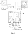
イメージング剤の投与後、目的の脈管構造または組織中に存在し得る薬剤のいずれかを励起できる装置と、こうした薬剤のいずれかから放射される放射線を検出できる装置とが活性化される。各装置は別個のハウジング中に与えられてもよいが、この発明からそれることなくそれらは単一のハウジング中に組合されてもよい。図1を参照すると、薬剤を励起するための装置は、それによって照射される目的の脈管構造または組織3内に位置するいずれかの薬剤が特定の波長の放射線を放射するようにさせる波長の放射線を放射するレーザ1を含むことが有利である。
【0047】
放射の検出を可能にするために十分に薬剤を励起するために好適な放射線を与え得るレーザは当業者に周知であり(例、マグナム3000、ラザリス サンローラン、ケベック、カナダ)、ここでは詳細に説明しない。しかし一般的に、その装置はレーザドライバおよびダイオードを含み、有利には帯域フィルタ5を含む。フィルタ5は、血管に到着する放射線が実質的に均一な波長、すなわち薬剤が蛍光を発するようにさせる波長であることを確実にすることによって、画像品質の最適化を助ける。
【0048】
レーザのみによって与えられる照明の範囲は吻合またはその他の比較的大きい領域を放射するのに不十分であるため、レーザは目的の領域を覆うためにレーザ光をそらせる光学部品7を含むことが有利である。例として、7.5cm×7.5cm領域の均一な照射を与える光学部品はほとんどの吻合を照射するために十分であることが見出された。こうした光学部品は周知であるため、ここでは詳細に説明しない。画像解像度を高めるために比較的小さい領域にレーザ放射線を集中させることが望ましいことがあるため、光学部品は照明の範囲を変動させ得ることが好ましい。
【0049】
さらなる任意の促進においては、パルス発生器18などの装置を用いることによって、レーザ出力がパルスにされ、カメラ画像取得速度と同期されてもよい。これによって、画像品質を保持しながら血管または組織が受取るレーザ放射線の量が減少される。
【0050】
イメージング剤からの放射を検出できる装置および特に好ましい蛍光染料もまた周知である。有利には、CCDカメラ2(例、日立KP−M2、KP−M3)などの、ある期間にわたって複数の画像を得ることができるカメラを用いてイメージング剤からの放射を捕捉してもよい。もちろん選択されるカメラは、イメージング剤によって放射される波長の放射線を捕捉できるものであるべきである。好ましくはカメラはこうした画像を少なくとも15画像/secの速度で、より好ましくは少なくとも約30画像/secの速度で捕捉すべきである。カメラはまた帯域フィルタ6と嵌合されることによって、イメージング剤から放射されたもの以外の放射線の捕捉を防いでもよい。
【0051】
カメラの焦点合わせは自動または手動手段によるものであってもよい。さらに、所望であれば、カメラは目的の領域を拡大可能にするレンズシステム8を含んでもよい。好ましくは、こうしたレンズシステムの使用がレーザに切換えられることによって、レンズシステムが係合されるときにはレーザによって与えられる照明の範囲が対応して減少し、レンズシステムによって与えられる視野を適合する。この協働の結果、解像度が高められる。解像度を高めるために、所望であればレーザおよび/またはカメラに偏光フィルタ14a、14bが嵌合されてもよい。
【0052】
装置の一部として距離センサ9(例、WTA24、ジックオプティックエレクトロニック社、イーデンプレーリー、MN)が含まれることが有利である。視覚ディスプレイ9aを組込むことが好ましいこのセンサは、医者にフィードバックを与えることによって、高品質画像を捕捉するために最適な目的の血管または組織からの距離にレーザおよびカメラを設置できるようにし、それによってその手順の間のカメラの焦点合わせの必要性を最小化する。
【0053】
カメラとレーザとの相対的な位置決めは、視覚ノイズとも呼ばれる画像明瞭度にも影響し得る。図1に示されるとおり、レーザはレーザおよびカメラの軸に関して、好ましくは約85°よりも小さく、より好ましくは約20°から70°である角度Θにて置かれる。これらの角度で体腔にレーザ放射線を導入することにより、体腔中に存在する液体によって起こる、カメラに入るグレアの量が減少される。
【0054】
図1に示されるとおり、カメラおよびレーザは患者の体外に配置される。
【0055】
カメラは捕捉した画像をアナログ−デジタル変換器10(典型的にはPC15内に位置するカード)に送り、次いでPC15上で実行する画像捕捉および処理ソフトウェアに通すことが好ましい。(目的の静脈、動脈および/または吻合の内腔に対応する)蛍光剤のデジタル画像は次いでモニタ11上に表示され、PCまたは周辺装置によって、たとえばハードドライブ、光ディスク、磁気テープなどのあらゆる好適な媒体に記録される。カメラはまた画像を直接テレビ12/VCR13システムに向けてもよく、画像はリアルタイムで表示されても、および/またはその後の再生のために記録されてもよい。モニタおよび/またはテレビは外科手術装置一式の中に設けられることにより、処置された血管および周囲の血管のさまざまな局面をリアルタイムで見せることを可能にすることが好ましい。また、カメラ、PCおよび/またはVCRにプリンタ16が接続されることによって1つまたはそれ以上の血管造影画像のハードコピーが得られるようにしてもよい。
【0056】
アナログ−デジタル変換器は周知である。この装置はその名が示すとおり、カメラが捕捉した一連のアナログ画像をデジタル画像に変換する。画像処理ソフトウェアもまた周知であり、処置された血管および近接する血管を分析できるさまざまなソフトウェアが現在入手可能である。
【0057】
実際には、カメラと、レーザと、ビデオモニタとを外科医に対向して置くことにより、外科医が患者に対してその装置を位置決めするための最大限の空間を有することを確実にすることが好ましい。残りの構成要素はあらゆる便利な場所に置かれてもよい。レーザ、カメラおよび/またはビデオモニタは、最大限の操作性を与えるためにx、yおよびz軸に沿った動きの自由度を与えかつ配置後に所望の位置に残る1つまたはそれ以上の枠組に取付けられることが好ましい。
【0058】
好ましい局面において、画像捕捉および処理ソフトウェアは、たとえば血管の処置された部分の直径および処置された部分に近接する本来の血管の端部分などの血管の直径の測定値を与えることができる。この測定値を与えるためにいくつかの異なる方法を用いることができるが、そうした方法の1つを以下に述べる。この発明は、カメラが各患者に対する異なる場所に位置決めされること、または1人の患者における1つよりも多くの血管の画像を得ることを予期するため、ソフトウェアはオペレータが画像画素の特定化された数に対する距離を割当てることを可能にする較正アルゴリズムを含むことが有利である。較正はあらゆる好適な方法を用いて完了され得るが、1つの方法は、たとえばICGなどの蛍光染料で満たされた公知の内径の毛細管の使用を含む。毛細管中の染料はレーザからの放射によって励起され、カメラによって検出されかつソフトウェアによって処理される、得られる蛍光を発する液体の画像を用いて、毛細管の内径に対応する画素の数に長さを割当てる。
【0059】
ソフトウェアは、分析のための最適な画像を選択するさらなる特徴を含むことが好ましい。こうした特徴を有することの必要性は、通常の条件下における目的の組織または処置された血管を通るイメージング剤の比較的速い流れに基づいている。目的の組織または血管を通る(そこを通過できるものがあれば)イメージング剤の通過のタイミングを正確に定めることはできないため、目的の画像の前および後に取得されるいくつかの先行および後続画像が存在する。ソフトウェアは、1つの画像と別のものとの相対的なコントラストを定め、この態様で分析のための最大のコントラストを有するフレーム、すなわち目的の血管または組織に薬剤が入り得る場合にはそ、中にイメージング剤が存在して検出可能な放射線を放射しているフレームを選択できることが好ましい。この選択された一連の画像が次いで分析され、特定の場所における処置された(またはあらゆるその他の)血管の直径、ならびに処置された血管および近接する本来の血管を通る血流の速度および量が定められてもよい。
【0060】
ソフトウェアはまた、処置前および処置後の血管の画像を比較することによって処置部位またはその下流における血液の相対的流速を定めるために用いられてもよい。この比較は、血管の予め選択された部分に関する処置前および処置後の画像中の蛍光の領域(すなわち蛍光染料に関連する画素の数)を計算および比較すること、および/またはこうした画像の各々における血管の予め選択された部分の相対的平均最大蛍光強度を比較することによって達成される。処置後の画像におけるより多数の画素、またはより大きい平均最大蛍光強度のそれぞれは、処置の結果として予め選択された血管部分の血流が改善したことを示す。
【0061】
同様にこの発明は、血管の直径を計算し、かつたとえばアセチルコリンの投与などの刺激の前および後の両方に比較することを可能にする。血管直径の増加はその血管が内皮機能を維持したことを示し、それは今後の血管開存性の正の指標であるため、この比較は重要である。
【0062】
この発明の利点について以下の例によってさらに例示する。ここに示される特定の詳細は、この発明の請求項に対する制限として解釈されるべきではない。
【0063】
(例)
この例は、特定の血管すなわちマウス大腿部動脈およびランゲンドルフ灌流された心臓を通る蛍光染料の流れの観察における、この発明の好ましい装置の用法を示し、また通常の状態および局所的に適用されたアセチルコリンの影響下の両方におけるマウス大腿部血管の直径を定めるこの装置の能力を示す。
【0064】
この例において、蛍光染料(ICG)は(マウスにおける頸静脈挿管を介して:ランゲンドルフ灌流心臓における点滴線を介して)血管床に注入され、レーザ源(806nm)からの放射線を用いて励起された。染料によって放射される蛍光(放射線)(830nm)は、CCDカメラを用いて一連の血管写像として捕捉された。カメラはその血管写像を、血管写像をデジタル化するPC上で実行するアナログ−デジタル変換ソフトウェアに送った。デジタル化された画像は(モニタを見ることによって)定性的にも定量的にも分析された。行なわれた定量的評価の一例は、PC上で実行するサブピクセル端縁検出システムを含むソフトウェアを用いるマウス大腿部動脈直径の決定であった。
【0065】
前述の蛍光イメージング技術は、in vivoのマウス大腿部動脈に用いられた。装置の各構成要素、動物の調製、ICGの注入、および分析法のより詳細な説明を以下の段落に示す。
【0066】
レーザ装置は、平均電流3.95Aの継続的な波出力を維持するSDL−820レーザダイオードドライバ(SDL社、サンホゼ、CA)と、SDL−2382−P1レーザダイオード(SDL社)とを含んだ。レーザダイオードは、目的の領域を照明してICG染料を励起することにより、イメージングされる領域中の蛍光を誘導するために用いられた。レーザダイオードが用いられたのは、白熱光源とは異なり、レーザは狭い周波数範囲のフォトンを放射するために励起フィルタの必要性および関連する熱損失の問題がなくなるためである。レーザが放射する波長は限られているため、励起フィルタをなくすことができ、蛍光が改善される。その結果、レーザダイオードから放射される光のより高い割合がICGによって吸収される波長のものとなる。800DF20帯域フィルタ(オメガオプティカル社、ブラトルバロ、VT)をレーザ光源とともに用いると、806nm(すなわちICGが励起される波長)において放射されるフォトンを選択的に通すことによって結果が改善されることが見出された。
【0067】
KP−160ビデオカメラ(日立電子株式会社、東京、日本)を用いて血管造影画像を回収した。KP−160カメラを選択したのは、それが電磁スペクトルの近赤外領域(ICGが蛍光を発するところでもある)において高感受性であり、励起されたICGから放射される放射線の捕捉を最適化するためである。ICG蛍光に関係しない波長のすべてのフォトンを取除くために、カメラに845DF25帯域フィルタ(オメガオプティカル社、ブラトルバロ、VT)を結合した。表面水から生じる鏡面反射率(すなわちグレア)を最小化してカメラに入るのを抑えるために、レーザダイオードは調査の領域に対して45°の角度にて位置決めされた。グレアはイメージングの際の視覚ノイズの主要な原因である。
【0068】
アナログ−デジタル変換器(752×480画素、8ビット画像プロセッサ、モデルPIXCI−SV4、エピックス(EPIX)社、バッファローグローブ、IL)は、カメラからの複合映像信号出力をデジタル化するために用いられた。
【0069】
ICG染料ボーラスの各IV注入の後、一連の264飛び越し画像が毎秒30の速度で回収された。
【0070】
マウスは、イソフルレン(オーメダファーマスーティカルプロダクツ(Ohmeda Pharmaceutical Products)、ミシソーガ、ON、カナダ)(医療用空気中に4%、4L/min)を用いて誘導箱中で麻酔を誘導することによって調製し、医療用空気(400mL/min)中に1.5−2.0%になるような空気速度でイソフルレンを与えるフェイスマスクの使用によって維持した。実験中、マウスは恒温水ブランケットの上に位置決めされ、直腸温度プローブによって体温がモニタされた。目的の血管のイメージングを促進ために、マウスの胸部、腹部および鼠径部領域をそり、マウスを仰向けに位置決めし、大腿部脈管構造の上の皮膚を切除して目的の脈管構造を露出させた。50Uヘパリン/mLを含む食塩水で満たされた1本の伸ばしたPE10管材を用いて頸静脈に挿管した。
【0071】
マウスを調製した後、ICGの10μlボーラスIV注入が施され、その後50μlの食塩水のIV注入が行なわれた。ボーラスを調製するために、注入の1時間以内に4μg/mlの臨床用等級のICG(カーディオグリーンTM)を滅菌水溶性溶剤に溶解した。すべての注入は頸静脈中に確立した挿管を介して施された。食塩水を用いて線にどっと流し、大腿部脈管構造を完全なボーラスが通過し、鋭い波面が生成されることを確認した。
【0072】
ウィンドウズ(R)95/98/NTバージョン1.0用のXCAP(エピックス社、バッファローグローブ、IL)を用いて画像分析を行なった。画像分析アルゴリズムは次のステップを含んだ。
【0073】
1.目的の血管の選択。脈管構造の解剖学的構造は動物によって異なる。したがって、目的の領域の選択に対する基準を開発する必要があった。このプロセスはカメラの位置決めから始まった。カメラの視界が大腿部動脈およびその分枝を含むようにカメラを位置決めした。画像分析の目的に対し、目的の血管は、最高の解像度および通常3次または4次の最大の程度の分枝を与える大腿部動脈および分枝であった。
【0074】
2.較正。イメージングされる領域に関するカメラの位置決めは各動物によって異なるため、回収される各画像に対してカメラを較正する必要があった。ICGで満たした小さい直径(320μm)の毛細管(TSP320450、ポリマイクロテクノロジーズ(Polymicro Technologies)、LLC、フェニックス、AZ)を用いて画像を較正した。イメージ処理ソフトウェアは、画素座標の組の特定化およびこれらの座標間の距離へのユーザが定めた値の割当を可能にする組込み較正機能を含む。ソフトウェアの端縁検出器を用いて、毛細管中で蛍光を発する染料の端縁の座標を定めた。次いで、ミクロンでの毛細管の内径をこれらの点の間の距離の「長さ」に割当てた。これはソフトウェアの組込み特徴であるため、画像のすべてのフレームにおけるその後の測定値はすべて画素単位ではなくミクロンで示された。
【0075】
カメラの動きまたはその他の確率的現象による歪みを防ぐために、すべての画像は較正された。この技術の利点は、血管を測定するために用いられるのと同じ方法を用いて較正装置を測定し、較正装置が血管と同じ光学条件下で同じフレームにおいて測定されることである。
【0076】
3.サブピクセルエッジャ(edger)を用いる直径の測定。すべての血管直径は組込みサブピクセルエッジャを用いて測定した。
【0077】
4.端縁強度に基づくフレームの選択。ICG画像の分析は、分析のためのフレームの選択を必要とする。フレームを選択する必要があるのは、画像取得の速度に対して大腿部動脈を通るICG流の速度が速いからである。その結果、イメージングされる領域においてICGが検出可能になる前および後にフレームの先行および後続シーケンスが取得される。ソフトウェア中の端縁検出器によって自動的に計算される端縁強度は、端縁の相対的強度の測定値、すなわち端縁の片側における画素の値の、他方側におけるそれらの値に対する比である。その比はコントラストが最大のときに最高になり、それはICG蛍光の最大強度に対応する。測定された血管は2つの端縁を有するため、端縁強度の積が最大である10個のフレームが分析のために選択された。
【0078】
上記が完了した後、前述のとおり血管の直径および標準誤差が計算された。対にした値に対するスチューデントのt−検定を適用して、測定間の統計的有意性を定めた(有意性の境界、p=0.01)。
【0079】
マウス(大腿部動脈)における異なる大きさの血管の影響の予備データを表に示す。このデータは、低濃度のアセチルコリン(0.01μM)が適用されるときにも小さい血管(例、58ミクロン)における変化をモニタできることを確かにする。
【0080】
【表1】

前述は、この発明が血管を通る血液の流れを観察し、血管の直径を定め、かつアセチルコリンの投与後の血管の反応性の変化をモニタすることができることを示す。
【0082】
特許、特許出願および出版物を含む、ここに示されるすべての参考文献をここに全体的に引用により援用する。さらに、他に示さない限り、ここでの単一の構成要素、構造またはステップに対する参照は、1つよりも多くのこうした構成要素、構造またはステップ、すなわち少なくとも1つまたは1つもしくはそれ以上を含むものとして解釈されるべきである。
【0083】
この発明について、好ましい実施例を強調しながら説明したが、通常の当業者には、この好ましい実施例の修正形が用いられてもよく、この発明はここに特定的に説明される以外の態様で行なわれてもよいことが意図されることが明らかになるであろう。したがってこの発明は、添付の請求項によって定められるこの発明の趣旨および範囲内に含まれるすべての変更形を含む。
【図面の簡単な説明】
【図1】 この発明の装置の好ましい実施例を概略的な形で例示する図である。[0001]
(Cross-reference to related patent applications)
This patent application claims the benefit of US Provisional Patent Application No. 60 / 155,652, filed September 24, 1999.
[0002]
(Technical field of the invention)
The present invention generally relates to a procedure for observing blood flow through an animal's cardiovascular system.
[0003]
(Background of the Invention)
Diseases and injuries affecting the cardiovascular system in animals, particularly humans, are common in today's society. One such disease is atherosclerosis. The disease is typically characterized by a partial blockage of a blood vessel (stenosis) by narrowing of one or more arteries. In the most severe form, the blood vessels narrow until they are completely occluded (occlusion). In coronary arteries, stenosis and occlusion often manifest in the form of severe chest pain and possibly myocardial infarction (heart attack). Atherosclerosis, not limited to coronary arteries, involves peripheral vasculature, arteries (and veins) that circulate blood to the arms and legs, carotid arteries, arteries that carry blood to the brain, and intracranial arteries, blood to the brain. It can also affect the arteries that distribute.
[0004]
One commonly used therapy in an effort to overcome the effects of atherosclerosis in coronary and peripheral vessels is bypass graft surgery. In this procedure, a vascular graft, such as a vein or artery or alternatively a flexible prosthetic tube, is surgically inserted in such a way that blood can bypass the narrowed or occluded portion of the original blood vessel. The best known example of bypass graft surgery would be coronary artery bypass graft (CABG) surgery. In CABG, grafts, typically saphenous veins or internal thoracic arteries, are taken or incised from a patient, respectively, and placed in the patient to allow blood flow to bypass stenotic or occluded vessel portions. Alternatively or additionally, a graft may be used to allow blood to flow directly from the aorta to a location downstream of the arterial stenosis or occlusion.
[0005]
The success of the bypass graft, at least for clinical improvement, depends in large part on the ability of the treated blood vessel to remain occluded both in the short and long term. Not causing this occlusion is commonly referred to as vascular patency. Insufficient patency in the months following surgery may be due to various factors, with the following being considered the most important: That is, inadequate blood circulation, insufficient coronary outflow, graft damage during preparation, or incomplete surgical techniques.
[0006]
Although recent cardiac surgery has focused on strategies to minimize trauma to the myocardium, these strategies can increase the likelihood of problems when used in vascular graft procedures. For example, while current surgical techniques allow CABG to be performed on a beating heart to minimize trauma, there are concerns regarding the quality of the resulting graft. Developed the use of limited access incisions during the CABG procedure for revascularization of the left anterior descending branch using at least the left internal thoracic artery, with the hope of faster recovery, shorter hospital stay and cost reduction It was done. However, this method also raised concerns regarding graft quality. In fact, early failures in grafts completed using restricted access incisions have been reported.
[0007]
Another problem affecting the CABG procedure is in diagnosis, the relatively late and inaccurate identification of stenotic and occluded vessels in the early phase of the CABG procedure (some of these vessels are present in the heart tissue) The degree of blood flow through a relatively small downstream vessel after the graft is completed (and more generally, whether the graft is successfully restoring blood flow to the affected tissue) ) Cannot be determined quickly and accurately.
[0008]
Arterial patency problems can occur even in therapies that do not involve grafts. For example, patency assessment is desirable in carotid arteries during and after endarterectomy, cranial blood vessels during and after neurosurgery, and renal hemodialysis where assessment of AV fistula patency is desirable. Blood patency information in these situations can be obtained using X-ray techniques, but the disadvantages mentioned above remain.
[0009]
The degree of blood flow in a particular tissue or part thereof is commonly referred to as perfusion, which is important in connection with the diagnosis and treatment of various diseases. For example, perfusion analysis is desirable in situations designed to reduce unwanted blood flow into the tissue, such as stopping blood flow to a tumor. Currently, MRI can be used to obtain perfusion information, but this information is inaccurate and is available only after the procedure is complete. This reduces the likelihood that the physician will be able to identify and mitigate problems during that same procedure, thereby eliminating the need for subsequent treatment procedures.
[0010]
Another disease that requires treatment of the circulatory system is renal dysfunction. In many cases of renal dysfunction, it is desirable to create an AV fistula to provide vascular access for hemodialysis. A fistula is created by joining arteries and veins by a surgical procedure, giving a blood vessel with relatively high blood flow. Although X-ray technology can be used to help a physician determine whether a well-functioning fistula can be generated and the type of fistula to be generated, this technique is subject to the aforementioned limitations.
[0011]
In view of the foregoing, there is a need for a diagnostic procedure that allows a physician to assess the patency of a particular blood vessel, and particularly a vessel that has undergone an invasive procedure such as a bypass graft procedure. There is also a further need for a method for quickly and accurately locating specific stenosis or occluded blood vessels such as coronary arteries during the initial phase of CABG surgery. In addition, an improved method for assessing the degree of blood flow downstream of the graft, such as in coronary arteries and peripheral vasculature, and a more accurate method for determining the degree of blood perfusion in selected body tissues Is needed. There is also a need for improved means for identifying candidate blood vessels for AV fistulas and obtaining information regarding determining the type of fistula to be generated in patients with renal impairment.
[0012]
(Summary of Invention)
The present invention, in one aspect, meets the above and other needs by providing a method for assessing the vascular patency of an animal, preferably during an invasive procedure in which the blood vessel is treated. . The method comprises the steps of administering a fluorescent dye to an animal, obtaining at least one angiographic image of the blood vessel portion, and evaluating the patency of the blood vessel portion by evaluating the at least one angiographic image. Including.
[0013]
A related aspect provides a method for assessing blood flow in a portion of an animal's tissue, where the tissue is a candidate for, is undergoing, or has undergone an invasive procedure. The method includes identifying a tissue portion of an animal, administering a fluorescent dye to the animal, obtaining at least one angiographic image of blood flowing through the tissue portion, and at least one Examining the angiographic image to assess blood flow in the tissue portion.
[0014]
A further aspect of the invention was improperly (or appropriately) perfused by allowing the physician to accurately determine the extent to which selected portions of body tissue such as heart tissue, tumors, etc. are well perfused. Helps identify and diagnose the organization. The method includes selecting a portion of body tissue to be analyzed, administering a fluorescent dye to a patient, obtaining at least one angiographic image of the selected tissue, and at least one angiographic image. Examining to assess the degree of blood flow within the selected portion of the body tissue.
[0015]
In a related aspect, the present invention provides methods for evaluating chemical agents and other proposed therapies with respect to their effects on vasculature. The method includes obtaining a first angiographic image of a selected vasculature, administering a therapeutic agent, and obtaining a second angiographic image of a selected vasculature at a later date. Comparing the first and second angiographic images to determine if there has been any change in blood vessel density during that period.
[0016]
In another aspect of the invention, a method is provided for locating at least one blood vessel (or a portion thereof) below the surface of vascularized tissue in an animal. The method includes administering a fluorescent dye to an animal, obtaining at least one angiographic image of a vasculature located below the surface of the tissue, and examining the at least one angiographic image of the surface of the tissue. Positioning at least one underlying blood vessel.
[0017]
In a further aspect, the present invention provides an apparatus for determining the diameter of a blood vessel. More specifically, the device can capture radiation emitted by the fluorescent dye in the vessel as an angiographic image that includes a plurality of pixels and a device that emits radiation that causes the fluorescent dye to fluoresce. A camera and a computer including a software program that calculates the diameter of the blood vessel by comparing the number of pixels corresponding to the blood vessel diameter with the number of pixels associated with a preselected unit of measurement.
[0018]
The foregoing and other features and advantages of the present invention will become apparent upon review of the accompanying drawings and the following detailed description of the preferred embodiments of the present invention.
[0019]
(Detailed explanation)
The method of the present invention is claimed and described herein as a series of treatment steps. It should be understood that these methods and associated steps may be performed in any logical order. In addition, the method may be performed alone, or other diagnostic procedures and previously performed during or after such methods and steps presented herein without departing from the scope and spirit of the invention. It may be performed in combination with treatment. Furthermore, the term animal as used herein is expected to include but not be limited to humans.
[0020]
In one aspect of the invention, a method is provided for analyzing patency of portions of an animal's blood vessels. The method comprises the steps of administering a fluorescent dye to an animal, obtaining at least one angiographic image of the blood vessel portion, and evaluating the patency of the blood vessel portion by evaluating the at least one angiographic image. Including.
[0021]
Illustrative blood vessels whose patency can be assessed according to the methods of this invention include coronary arteries, peripheral vasculature, carotid arteries, intracranial vessels and AV fistulas. Vascular patency assessment may be done qualitatively by visual inspection of the images, and if desired, may be done quantitatively by obtaining measurements of vessel diameter, where It is desirable that the lumen of a specific blood vessel portion has a substantially uniform diameter.
[0022]
Advantageously, vascular patency may be defined during an invasive procedure. For the purposes of this and other aspects of the invention, an invasive procedure is one in animal tissue to diagnose or treat a disease or condition that directly or indirectly affects vasculature or tissue. Or a procedure in which a further incision is made or an instrument is placed in the opening of the animal. It should be understood that this invasive procedure continues until each incision is sutured or the instrument is removed from the animal.
[0023]
By way of example, this aspect of the invention contemplates that a physician will obtain angiographic images of coronary arteries both before and after a procedure (eg, bypass) during a single invasive procedure. In this manner, the physician can quickly assess the patency of the treated blood vessel. This is beneficial because if the doctor becomes aware of the problem with the treated blood vessel, he can take therapeutic measures during the same invasive procedure, and the animal will have no trauma associated with the subsequent therapeutic invasive procedure. .
[0024]
Examples of vascular segments that may benefit from using the methods of the invention include repair (for injury, aneurysm and / or malformation) or bypass (for coronary or peripheral vasculature), endarterectomy, This includes, but is not limited to, blood vessels that have undergone intracranial surgery, generation of AV fistulas, and surgical procedures performed using an endoscope or associated device.
[0025]
Illustrative of the types of repairs are closure of the torn vessel by suturing or adhering and removing the undesired portion of the vessel, followed by joining the two remaining ends of the vessel together, or a natural or synthetic vessel Including, but not limited to, removing an aneurysm or other vascular malformation by placing the graft at the end of the remaining vessel and then joining.
[0026]
Bypass is commonly used when a portion of a blood vessel, typically a stenosis or occlusion, requires a bypass. Bypass attaches the end of the graft vessel upstream and downstream of the stenosis, occlusion or other problem area, and relatively healthy arteries to the undesired blood vessel in the location downstream of the stenosis, occlusion or other problem area. Including, but not limited to, grafting one end of. One particular example of the latter is a procedure in which one end of a healthy artery from the chest wall is grafted downstream of a stenotic or occluded portion of the coronary artery. The method of the present invention is preferably used in surgery involving coronary artery bypass, such as CABG surgery.
[0027]
When the bypass is performed, an anastomosis, i.e., a junction between the native vessel and the graft vessel, is created. The patency of the anastomosis is particularly important for the doctor. In a preferred aspect, the method of the invention anticipates an assessment of patency of the anastomosis, more preferably during an invasive procedure, most preferably when the heart remains beating.
[0028]
A further aspect of the invention provides a method for assessing blood flow in a portion of animal tissue, wherein the tissue is a candidate for, has undergone or has undergone an invasive procedure. is there. In the latter case, the assessment of the degree of blood flow through the vasculature located downstream of the treated blood vessel helps the physician assess the success of the treatment. The method includes identifying a portion of animal tissue, administering a fluorescent dye to the animal, obtaining at least one angiographic image of blood flowing through the tissue portion, and at least one angiographic image. And evaluating to assess blood flow in the tissue portion.
[0029]
This method may be advantageously used for blood flow assessment in coronary arteries and peripheral vasculature, and is preferably used during invasive procedures. In one preferred aspect, the method assesses the success of the bypass procedure by obtaining an angiographic image of the vasculature located downstream of a particular blood vessel, eg, a coronary artery, that has undergone a procedure such as bypass. Expect to do. In another preferred aspect, the method expects to obtain an angiographic image of the vasculature located downstream of a particular peripheral blood vessel that has undergone treatment, such as peripheral vascular bypass, the image being downstream vasculature Obtained without incising the overlying skin. In the latter aspect, the treated peripheral vasculature and / or downstream vasculature is preferably located at a depth below the skin surface to allow assessment of the desired vasculature. This depth is preferably at least about 0.5 cm, more preferably at least about 1 cm below the skin surface.
[0030]
This aspect of the invention further contemplates assessing blood flow in other body tissues including but not limited to muscle, stomach, liver, intestine, bladder, esophagus, lung, kidney and brain tissue. Angiographic images may be obtained from below the surface of these tissues not exceeding a depth that allows for the assessment of the desired vasculature. Again and preferably, this depth is at least about 0.5 cm, more preferably at least about 1 cm from any surface of the aforementioned tissue, and endoscopic access to the tissue is the preferred path. . This method may be used in connection with various invasive procedures, such as, for example, a procedure for assessing whether internal bleeding has stopped. For example, a physician can easily determine whether a surgical procedure has successfully stopped bleeding that was previously a bleeding ulcer.
[0031]
The methods of the present invention further provide a means to evaluate various therapies, and the success of such therapies is at least partially indicated by the degree of blood flow in or around a particular tissue. The method includes obtaining a first angiographic image of a selected tissue, applying a therapy (eg, a proposed therapeutic compound) to the animal, and thereafter (eg, hours, days or months). ) Obtaining a second angiographic image of the same selected tissue and comparing the first and second images to determine if there has been any change in blood vessel density and / or blood flow in the tissue I expect. One use of this method is in the evaluation of angiogenic and antiangiogenic agents, and the study of such possible therapies. For example, if there is a particular therapy's impact on entering and / or reducing blood flow through a tumor, such as a lung or colon tumor, it may be assessed using an endoscope.
[0032]
In another aspect of the invention, a method is provided for locating a blood vessel underlying the surface of vascularized tissue, such as a blood vessel suitable for the generation of a stenotic or occluded artery or AV fistula. The method includes administering a fluorescent dye to an animal, obtaining at least one angiographic image of a vasculature located below the surface of the tissue, and examining the at least one angiographic image of the surface of the tissue. Positioning at least one underlying blood vessel.
[0033]
Because this method can easily visualize blood vessels located at least about 0.5 cm, and preferably at least about 1 cm below the tissue surface, the physician can save time locating the blood vessel to be treated, thereby saving the tissue surface. Bypass or other coronary procedures, including locating the underlying stenosis or occluded vessel, could be completed in less time.
[0034]
In the context of renal dysfunction, this method is a means of determining suitable arterial and venous locations for the generation of AV fistulas, as well as information to help the doctor determine what kind of fistulas to generate based on the vasculature. Provide a means to give In a preferred aspect, the method makes it possible to obtain angiographic images of peripheral vasculature located up to the aforementioned depth without having to cut through the skin to expose the target vasculature.
[0035]
Angiographic images obtained without incision are assessed for peripheral (upper and lower end) vasculature bypass (by assessing blood flow through the vasculature downstream of the bypass), and (under the nail bed) It may also be useful in assessing nail bed endothelial dysfunction (by assessing the extent of blow flow through the located capillary).
[0036]
Angiographic images obtained according to various aspects of the present invention show lumens (spaces) inside arteries and veins located within the target tissue. A relatively thick line indicates the main artery and a relatively thin line indicates the smaller artery. A line of substantially uniform thickness indicates a blood vessel without atherosclerotic plaque. In contrast, a bumpy line or a line that narrows in a specific portion indicates the presence of a stenosis, and where the line is broken indicates the presence of an occlusion.
[0037]
In yet another aspect, the present invention provides an apparatus and associated method for providing high resolution images that allow a physician to determine vessel diameters up to about 30 μm and below. This aspect of the invention is discussed in more detail in the following paragraphs.
[0038]
To obtain an image according to various aspects of the invention, a fluorescent imaging agent is administered to the patient. The fluorescent agent should be selected so that it can obtain at least one useful image of the vasculature as it passes through the desired vasculature. A fluorescent dye emits radiation of a known wavelength when excited by radiation of a particular wavelength. The radiation emitted by the excited dye is detectable and may be captured by a suitable device that converts the radiation into a visible image.
[0039]
Any fluorescent dye that provides an image as described herein may be used, but indocyanine green (ICG) (IC-greenTM, Cardio-GREENTM, Sold by Acorn), similar elements of tricarbocyanine dyes, and mixtures thereof. ICG is readily available and preferred because it has long been approved for human administration for eye angiography, cardiac output analysis and other indications.
[0040]
The wavelengths for both absorption and emission of radiation for such dyes are well known and will not be repeated here. As an example, however, the peak absorption and emission of ICG is in the range of 800-850 nm, so a radiation source emitting these wavelengths should be used to obtain one or more images of the blood vessel or tissue of interest. .
[0041]
Typically, the fluorescent agent is administered in a composition comprising a pharmaceutically acceptable carrier. The amount of composition administered and the concentration of fluorescent agent present should be sufficient to give the desired degree of detail in the image. Advantageously, the drug is present in an amount of about 1 to about 10 mg / ml, preferably about 3 to about 7 mg / ml, more preferably about 5 mg / ml of the composition, with the carrier constituting the balance.
[0042]
Carriers that advantageously solvate the drug but may simply emulsify or suspend are provided to facilitate administration of the drug to the patient. Administration is typically performed by parenteral IV infusion or other suitable means, with IV infusion of the composition as a bolus, and the carrier selected in view of the desired mode of administration.
[0043]
Exemplary carriers that can be used are water, saline, alcohol, glycerin, polyethylene glycol, propylene glycol, polysorbate 80, tween, liposomes, amino acids, lecithin, dodecyl sulfate, lauryl sulfate, phospholipid, Cremophor, desoxycholate. , Soybean oil, vegetable oil, safflower oil, sesame oil, peanut oil, cottonseed oil, sorbitol, gum arabic, aluminum monostearate, polyoxyethylated fatty acid, povidone and mixtures thereof. Advantageously, the carrier comprises water and / or saline.
[0044]
Optional ingredients that may be present with the drug in the composition include tonicity and / or pH adjusting agents such as NaOH, HCl, phosphate buffer, Tris buffer and the like.
[0045]
The composition comprising the drug may be initially given in any suitable formulation, for example in a vial or syringe, as a lyophilized form for reconstitution prior to use, or as a liquid premix.
[0046]
After administration of the imaging agent, a device capable of exciting any of the agents that may be present in the target vasculature or tissue and a device capable of detecting radiation emitted from any of these agents are activated. Each device may be provided in a separate housing, but they may be combined in a single housing without departing from this invention. Referring to FIG. 1, an apparatus for exciting a drug has a wavelength that causes any drug located within the target vasculature or
[0047]
Lasers that can provide radiation suitable to excite the drug sufficiently to allow detection of radiation are well known to those skilled in the art (eg, Magnum 3000, Lazaris Saint Laurent, Quebec, Canada), and are described in detail here. I do not explain. In general, however, the device comprises a laser driver and a diode, preferably a
[0048]
Since the range of illumination provided by the laser alone is insufficient to emit anastomoses or other relatively large areas, it is advantageous for the laser to include an
[0049]
In a further optional enhancement, the laser output may be pulsed and synchronized with the camera image acquisition rate by using a device such as
[0050]
Devices capable of detecting radiation from imaging agents and particularly preferred fluorescent dyes are also well known. Advantageously, radiation from the imaging agent may be captured using a camera that can obtain multiple images over a period of time, such as a CCD camera 2 (eg, Hitachi KP-M2, KP-M3). Of course, the camera selected should be capable of capturing radiation at the wavelength emitted by the imaging agent. Preferably the camera should capture such images at a rate of at least 15 images / sec, more preferably at a rate of at least about 30 images / sec. The camera may also be fitted with a bandpass filter 6 to prevent capture of radiation other than that emitted from the imaging agent.
[0051]
Camera focusing may be by automatic or manual means. Further, if desired, the camera may include a
[0052]
Advantageously, a distance sensor 9 (eg WTA 24, Gick Optic Electronic, Eden Prairie, MN) is included as part of the device. This sensor, which preferably incorporates a visual display 9a, allows the doctor and the camera to be placed at the optimum distance from the target vessel or tissue to capture high quality images by providing feedback to the doctor, thereby Minimize the need for camera focusing during the procedure.
[0053]
The relative positioning of the camera and laser can also affect image clarity, also called visual noise. As shown in FIG. 1, the laser is positioned at an angle Θ that is preferably less than about 85 ° and more preferably about 20 ° to 70 ° with respect to the laser and camera axes. By introducing laser radiation into the body cavity at these angles, the amount of glare entering the camera caused by the liquid present in the body cavity is reduced.
[0054]
As shown in FIG. 1, the camera and laser arePlaced outside the body.
[0055]
The camera preferably sends the captured image to an analog-to-digital converter 10 (typically a card located in the PC 15), which then passes through image capture and processing software running on the
[0056]
Analog-to-digital converters are well known. As the name implies, this device converts a series of analog images captured by the camera into digital images. Image processing software is also well known, and various software is currently available that can analyze treated and adjacent blood vessels.
[0057]
In practice, it is preferable to place the camera, laser, and video monitor opposite the surgeon to ensure that the surgeon has the maximum space to position the device relative to the patient. . The remaining components may be placed in any convenient location. Lasers, cameras and / or video monitors provide one or more frameworks that provide freedom of movement along the x, y and z axes for maximum operability and remain in the desired position after placement. Preferably it is attached.
[0058]
In a preferred aspect, the image capture and processing software can provide measurements of the diameter of a blood vessel, such as the diameter of the treated portion of the blood vessel and the end portion of the native blood vessel proximate to the treated portion. Several different methods can be used to provide this measurement, one of which is described below. Since the invention expects the camera to be positioned at a different location for each patient, or to obtain images of more than one blood vessel in a patient, the software will allow the operator to identify image pixels. It is advantageous to include a calibration algorithm that makes it possible to assign distances to any number. While calibration can be completed using any suitable method, one method involves the use of a known inner diameter capillary filled with a fluorescent dye such as, for example, ICG. The dye in the capillary is excited by the radiation from the laser, and is assigned a length to the number of pixels corresponding to the inner diameter of the capillary using the resulting fluorescent image of the liquid that is detected by the camera and processed by software. .
[0059]
The software preferably includes additional features that select the optimal image for analysis. The need to have such characteristics is based on the relatively fast flow of imaging agent through the tissue of interest or treated blood vessel under normal conditions. Since it is not possible to accurately determine the timing of imaging agent passage through the target tissue or blood vessel (if there is anything that can pass through it), several previous and subsequent images acquired before and after the target image Exists. The software determines the relative contrast between one image and another, and in this way the frame with the greatest contrast for analysis, i.e. if the drug can enter the target vessel or tissue, It is preferable to be able to select a frame that emits detectable radiation in the presence of an imaging agent. This selected series of images is then analyzed to determine the diameter of the treated (or any other) vessel at a particular location, and the velocity and volume of blood flow through the treated vessel and the adjacent native vessel. May be.
[0060]
The software may also be used to determine the relative flow rate of blood at or downstream of the treatment site by comparing pre- and post-treatment blood vessel images. This comparison may include calculating and comparing the area of fluorescence in the pre-treatment and post-treatment images (ie, the number of pixels associated with the fluorescent dye) for a pre-selected portion of the blood vessel and / or in each such image This is accomplished by comparing the relative mean maximum fluorescence intensity of preselected portions of the blood vessel. Each of a greater number of pixels in the post-treatment image, or a larger average maximum fluorescence intensity, indicates that blood flow in the preselected vessel portion has improved as a result of the treatment.
[0061]
Similarly, the present invention allows blood vessel diameters to be calculated and compared both before and after stimulation, eg, administration of acetylcholine. This comparison is important because an increase in vessel diameter indicates that the vessel maintained endothelial function, which is a positive indicator of future vessel patency.
[0062]
The advantages of this invention are further illustrated by the following examples. The specific details set forth herein should not be construed as limitations on the claims of this invention.
[0063]
(Example)
This example demonstrates the use of the preferred device of this invention in observing the flow of fluorescent dyes through specific blood vessels, ie mouse femoral artery and Langendorff-perfused heart, and has been applied to normal conditions and topically The ability of this device to determine the diameter of mouse femoral vessels both under the influence of acetylcholine is shown.
[0064]
In this example, fluorescent dye (ICG) was injected into the vascular bed (via jugular vein intubation in mice: via drip lines in Langendorff perfused hearts) and excited using radiation from a laser source (806 nm). . The fluorescence (radiation) emitted by the dye (830 nm) was captured as a series of blood vessel maps using a CCD camera. The camera sent the vessel map to analog-to-digital conversion software running on a PC that digitizes the vessel map. The digitized images were analyzed qualitatively and quantitatively (by looking at the monitor). An example of a quantitative assessment performed was the determination of mouse femoral artery diameter using software that includes a subpixel edge detection system running on a PC.
[0065]
The aforementioned fluorescence imaging technique has been used on mouse femoral arteries in vivo. A more detailed description of each component of the device, animal preparation, ICG injection, and analytical method is given in the following paragraphs.
[0066]
The laser device included an SDL-820 laser diode driver (SDL, San Jose, Calif.) That maintained a continuous wave output with an average current of 3.95 A, and an SDL-2382-P1 laser diode (SDL). Laser diodes were used to induce fluorescence in the area to be imaged by illuminating the area of interest and exciting the ICG dye. The laser diode was used because, unlike incandescent light sources, the laser emits photons in a narrow frequency range, eliminating the need for an excitation filter and the associated heat loss problems. Since the wavelength emitted by the laser is limited, the excitation filter can be eliminated and the fluorescence is improved. As a result, a higher percentage of the light emitted from the laser diode is of a wavelength that is absorbed by the ICG. When an 800DF20 bandpass filter (Omega Optical, Brattleboro, VT) is used with a laser source, it is found that the results are improved by selectively passing photons emitted at 806 nm (ie, the wavelength at which the ICG is excited). It was done.
[0067]
Angiographic images were collected using a KP-160 video camera (Hitachi Electronics Co., Ltd., Tokyo, Japan). The KP-160 camera was chosen because it is highly sensitive in the near infrared region of the electromagnetic spectrum (where the ICG also fluoresces) and optimizes the capture of radiation emitted from the excited ICG Because. An 845DF25 bandpass filter (Omega Optical, Brattleboro, VT) was coupled to the camera to remove all photons of wavelengths not related to ICG fluorescence. The laser diode was positioned at a 45 ° angle with respect to the study area to minimize specular reflectance (ie, glare) arising from surface water and to prevent entry into the camera. Glare is a major cause of visual noise during imaging.
[0068]
An analog-to-digital converter (752 × 480 pixels, 8-bit image processor, model PIXCI-SV4, EPIX, Buffalo Grove, IL) was used to digitize the composite video signal output from the camera. .
[0069]
After each IV injection of ICG dye bolus, a series of 264 interlaced images were collected at a rate of 30 per second.
[0070]
Mice are prepared by inducing anesthesia in an induction box with isoflurane (Ohmeda Pharmaceutical Products, Mississauga, ON, Canada) (4% in medical air, 4 L / min). And maintained by the use of a face mask that provides isoflurane at an air velocity of 1.5-2.0% in medical air (400 mL / min). During the experiment, mice were positioned on a constant temperature blanket and body temperature was monitored by a rectal temperature probe. To facilitate imaging of the target vessel, shave the chest, abdomen and groin areas of the mouse, position the mouse on its back, and remove the skin above the femoral vasculature to expose the target vasculature I let you. The jugular vein was intubated using one stretched PE10 tubing filled with saline containing 50 U heparin / mL.
[0071]
After the mice were prepared, a 10 μl bolus IV infusion of ICG was given followed by an IV infusion of 50 μl saline. To prepare the bolus, 4 μg / ml clinical grade ICG (Cardio Green within 1 hour of injection)TM) Was dissolved in a sterile water-soluble solvent. All infusions were given via established intubations in the jugular vein. Line with saline solutionFastIt was confirmed that a complete bolus passed through the femoral vasculature and a sharp wavefront was generated.
[0072]
Image analysis was performed using XCAP (Epics, Buffalo Grove, IL) for Windows (R) 95/98 / NT version 1.0. The image analysis algorithm included the following steps.
[0073]
1. Selection of the desired blood vessel. The anatomy of the vasculature varies from animal to animal. Therefore, it was necessary to develop criteria for the selection of target areas. This process began with camera positioning. The camera was positioned so that the camera field of view included the femoral artery and its branches. For purposes of image analysis, the vessels of interest were the femoral artery and branches that gave the highest resolution and usually the greatest degree of branching in the third or fourth order.
[0074]
2. calibration. Since the positioning of the camera relative to the area to be imaged is different for each animal, it was necessary to calibrate the camera for each image collected. Images were calibrated using small diameter (320 μm) capillaries (TSP320450, Polymicro Technologies, LLC, Phoenix, AZ) filled with ICG. The image processing software includes a built-in calibration function that allows the specification of a set of pixel coordinates and the assignment of user defined values to the distance between these coordinates. A software edge detector was used to determine the coordinates of the edge of the dye that fluoresces in the capillary. The capillary inner diameter in microns was then assigned to the “length” of the distance between these points. Since this is a built-in feature of the software, all subsequent measurements in every frame of the image were shown in microns rather than in pixels.
[0075]
All images were calibrated to prevent distortion due to camera movement or other stochastic phenomena. The advantage of this technique is that the calibration device is measured using the same method used to measure the blood vessel, and the calibration device is measured in the same frame under the same optical conditions as the blood vessel.
[0076]
3. Diameter measurement using a subpixel edger. All vessel diameters were measured using a built-in subpixel edger.
[0077]
4). Frame selection based on edge strength. Analysis of ICG images requires selection of a frame for analysis. The frame needs to be selected because the speed of the ICG flow through the femoral artery is faster than the speed of image acquisition. As a result, prior and subsequent sequences of frames are acquired before and after the ICG becomes detectable in the area to be imaged. The edge strength automatically calculated by the edge detector in the software is a measure of the relative strength of the edge, i.e. the ratio of the pixel values on one side of the edge to their values on the other side . The ratio is highest when the contrast is maximum, which corresponds to the maximum intensity of ICG fluorescence. Since the measured blood vessel has two edges, ten frames with the largest edge strength product were selected for analysis.
[0078]
After the above was completed, the vessel diameter and standard error were calculated as described above. Student's t-test for paired values was applied to determine statistical significance between measurements (significance boundary, p = 0.01).
[0079]
Preliminary data on the effects of different sized blood vessels in mice (femoral artery) are shown in the table. This data confirms that changes in small blood vessels (eg, 58 microns) can be monitored even when low concentrations of acetylcholine (0.01 μM) are applied.
[0080]
[Table 1]
The foregoing shows that the present invention can observe blood flow through blood vessels, determine blood vessel diameter, and monitor changes in blood vessel reactivity after administration of acetylcholine.
[0082]
All references cited herein, including patents, patent applications and publications, are hereby incorporated by reference in their entirety. Further, unless otherwise indicated, a reference herein to a single component, structure or step includes more than one such component, structure or step, ie, at least one or one or more. Should be interpreted as things.
[0083]
While this invention has been described with emphasis on preferred embodiments, modifications to this preferred embodiment may be used by those of ordinary skill in the art and the invention is not limited to that specifically described herein. It will be clear that it may be done in Accordingly, this invention includes all modifications encompassed within the spirit and scope of the invention as defined by the appended claims.
[Brief description of the drawings]
FIG. 1 schematically illustrates a preferred embodiment of the apparatus of the present invention in schematic form.
Claims (11)
前記蛍光染料を励起させる第1の放射線を放射する放射手段と、
前記冠状動脈バイパスグラフト中の前記蛍光染料が放射した第2の放射線を検出して該冠状動脈バイパスグラフトの造影画像を取得するカメラと、
を備え、
前記放射手段及び前記カメラは、患者の体外に配置され、
前記蛍光染料は、ICGであり、
前記第1及び第2の放射線の波長は、ICGを使用するための励起及び放射スペクトルの帯域にあり、
前記カメラは、可視スペクトルの外にある放射線を可視像として視覚化することが可能であり、少なくとも毎秒15画像の速度で前記冠状動脈バイパスグラフトの造影画像を取得し、
前記ICGを含んだ血流が作る波面が視覚化されることを特徴とする装置。A device that visualizes the movement of fluorescent dyes carried in the bloodstream in a coronary artery bypass graft during surgery,
Radiation means for emitting a first radiation for exciting the fluorescent dye;
A camera for acquiring a contrast image of the coronary artery bypass grafts to detect a second radiation the fluorescent dye of the coronary artery bypass in the graft has been radiated,
With
The radiation means and the camera are arranged outside the body of a patient;
The fluorescent dye is ICG;
The wavelengths of the first and second radiation are in the bands of excitation and emission spectra for using ICG;
The camera is capable of visualizing radiation outside the visible spectrum as a visible image, acquiring a contrast image of the coronary artery bypass graft at a rate of at least 15 images per second;
A device characterized in that a wavefront created by a blood flow containing the ICG is visualized.
前記装置は、前記第1の放射線が注目領域を覆うように配置された光学部品をさらに備えることを特徴とする請求項1乃至6のいずれか1項に記載の装置。The radiation means is a laser;
The apparatus according to any one of claims 1 to 6, further comprising an optical component arranged so that the first radiation covers a region of interest.
前記蛍光染料を励起させる第1の放射線を放射する放射手段と、
前記冠状動脈バイパスグラフト中の前記蛍光染料が放射した第2の放射線を検出して該冠状動脈バイパスグラフトの造影画像を取得するカメラと、
を備え、
前記放射手段及び前記カメラは、患者の体外に配置され、
前記蛍光染料は、食塩水によってボーラスとして一気に流せる、ICGを含む組成物であり、
前記第1及び第2の放射線の波長は、ICGを使用するための励起及び放射スペクトルの帯域にあり、
前記カメラは、可視スペクトルの外にある放射線を可視像として視覚化することが可能であり、少なくとも毎秒15画像の速度で前記冠状動脈バイパスグラフトの造影画像を取得し、
前記冠状動脈バイパスグラフトにおける血流が、ボーラスが作る波面によって視覚化されることを特徴とする装置。A device that visualizes the movement of fluorescent dyes carried in the bloodstream in a coronary artery bypass graft during surgery,
Radiation means for emitting a first radiation for exciting the fluorescent dye;
A camera for acquiring a contrast image of the coronary artery bypass grafts to detect a second radiation the fluorescent dye of the coronary artery bypass in the graft has been radiated,
With
The radiation means and the camera are arranged outside the body of a patient;
The fluorescent dye is a composition containing ICG that can be swept as a bolus with saline.
The wavelengths of the first and second radiation are in the bands of excitation and emission spectra for using ICG;
The camera is capable of visualizing radiation outside the visible spectrum as a visible image, acquiring a contrast image of the coronary artery bypass graft at a rate of at least 15 images per second;
A device in which blood flow in the coronary artery bypass graft is visualized by a wavefront created by a bolus.
Applications Claiming Priority (3)
| Application Number | Priority Date | Filing Date | Title |
|---|---|---|---|
| US15565299P | 1999-09-24 | 1999-09-24 | |
| US60/155,652 | 1999-09-24 | ||
| PCT/US2000/022088 WO2001022870A1 (en) | 1999-09-24 | 2000-08-11 | Method and apparatus for performing intra-operative angiography |
Related Child Applications (1)
| Application Number | Title | Priority Date | Filing Date |
|---|---|---|---|
| JP2006016878A Division JP2006192280A (en) | 1999-09-24 | 2006-01-25 | Method and apparatus for performing intra-operative angiography |
Publications (3)
| Publication Number | Publication Date |
|---|---|
| JP2003510121A JP2003510121A (en) | 2003-03-18 |
| JP2003510121A5 JP2003510121A5 (en) | 2006-05-18 |
| JP3881550B2 true JP3881550B2 (en) | 2007-02-14 |
Family
ID=22556243
Family Applications (3)
| Application Number | Title | Priority Date | Filing Date |
|---|---|---|---|
| JP2001526090A Expired - Lifetime JP3881550B2 (en) | 1999-09-24 | 2000-08-11 | Device for performing intraoperative angiography |
| JP2006016878A Pending JP2006192280A (en) | 1999-09-24 | 2006-01-25 | Method and apparatus for performing intra-operative angiography |
| JP2011053502A Expired - Lifetime JP5081992B2 (en) | 1999-09-24 | 2011-03-10 | Method and apparatus for performing intraoperative angiography |
Family Applications After (2)
| Application Number | Title | Priority Date | Filing Date |
|---|---|---|---|
| JP2006016878A Pending JP2006192280A (en) | 1999-09-24 | 2006-01-25 | Method and apparatus for performing intra-operative angiography |
| JP2011053502A Expired - Lifetime JP5081992B2 (en) | 1999-09-24 | 2011-03-10 | Method and apparatus for performing intraoperative angiography |
Country Status (15)
| Country | Link |
|---|---|
| EP (6) | EP2281503B1 (en) |
| JP (3) | JP3881550B2 (en) |
| KR (1) | KR100737620B1 (en) |
| CN (3) | CN101264014B (en) |
| AT (2) | ATE506005T1 (en) |
| AU (1) | AU782257B2 (en) |
| BR (1) | BR0014289A (en) |
| CA (1) | CA2339214C (en) |
| DE (2) | DE60036781T2 (en) |
| DK (2) | DK2910185T3 (en) |
| ES (2) | ES2666182T3 (en) |
| HK (3) | HK1040897B (en) |
| MX (1) | MXPA02003064A (en) |
| PT (2) | PT1143852E (en) |
| WO (1) | WO2001022870A1 (en) |
Families Citing this family (69)
| Publication number | Priority date | Publication date | Assignee | Title |
|---|---|---|---|---|
| US20050182434A1 (en) | 2000-08-11 | 2005-08-18 | National Research Council Of Canada | Method and apparatus for performing intra-operative angiography |
| AU2003248559A1 (en) * | 2002-05-22 | 2003-12-12 | Beth Israel Deaconess Medical Center | Device for wavelength-selective imaging |
| JP2004163413A (en) | 2002-08-28 | 2004-06-10 | Carl-Zeiss-Stiftung Trading As Carl Zeiss | Microscope system and microscope inspection method |
| JP4013128B2 (en) * | 2002-09-12 | 2007-11-28 | 株式会社日立メディコ | Blood flow dynamic analysis apparatus, method, and diagnostic imaging apparatus |
| AU2003282373A1 (en) * | 2002-11-29 | 2004-06-23 | Given Imaging Ltd. | Methods device and system for in vivo diagnosis |
| DE10257743B4 (en) * | 2002-12-10 | 2006-11-23 | Irmgard Zerrle | Device for determining perfusion in a tissue region and blood flow through individual blood vessels |
| CN100443042C (en) | 2003-11-20 | 2008-12-17 | 浜松光子学株式会社 | Lymph node detector |
| DE102004015682B4 (en) * | 2004-03-26 | 2008-07-31 | Bundesrepublik Deutschland, vertr. d. d. Bundesministerium für Wirtschaft und Technologie, dieses vertr. d. d. Präsidenten der Physikalisch-Technischen Bundesanstalt | Method and device for detecting a dye bolus injected into the body of a living being |
| JP2006014868A (en) | 2004-06-30 | 2006-01-19 | Hamamatsu Photonics Kk | Lymph node detecting apparatus |
| US8185176B2 (en) * | 2005-04-26 | 2012-05-22 | Novadaq Technologies, Inc. | Method and apparatus for vasculature visualization with applications in neurosurgery and neurology |
| US20060239921A1 (en) | 2005-04-26 | 2006-10-26 | Novadaq Technologies Inc. | Real time vascular imaging during solid organ transplant |
| US20060264783A1 (en) * | 2005-05-09 | 2006-11-23 | Holmes Elizabeth A | Systems and methods for monitoring pharmacological parameters |
| JP4709600B2 (en) * | 2005-07-15 | 2011-06-22 | 株式会社東芝 | X-ray diagnostic apparatus, imaging angle optimization support apparatus, and program |
| US20070122344A1 (en) | 2005-09-02 | 2007-05-31 | University Of Rochester Medical Center Office Of Technology Transfer | Intraoperative determination of nerve location |
| DE102006004583A1 (en) | 2006-02-01 | 2007-08-09 | Siemens Ag | Optical scanner, to give images of marked human and animal tissue, has a distance sensor with a control unit to set the focus of the infra red light source for the image detector |
| RU2309668C1 (en) | 2006-02-20 | 2007-11-10 | Александр Сергеевич Парфенов | Method and device for non-invasive measurement of function of endothelium |
| JP4954573B2 (en) | 2006-02-28 | 2012-06-20 | オリンパス株式会社 | Endoscope system |
| US20080161744A1 (en) | 2006-09-07 | 2008-07-03 | University Of Rochester Medical Center | Pre-And Intra-Operative Localization of Penile Sentinel Nodes |
| KR100867977B1 (en) * | 2006-10-11 | 2008-11-10 | 한국과학기술원 | Machine to analyze tissue perfusion using concentration of indocyanine green in blood and a method for analysing tissue perfusion using the same |
| KR100818669B1 (en) * | 2007-03-09 | 2008-04-02 | 한국과학기술원 | Apparatus for measuring the perfusion rate of legs |
| JP5476317B2 (en) * | 2008-01-25 | 2014-04-23 | ノバダック テクノロジーズ インコーポレイテッド | Method and system for assessing brush in myocardial tissue |
| US8406860B2 (en) | 2008-01-25 | 2013-03-26 | Novadaq Technologies Inc. | Method for evaluating blush in myocardial tissue |
| BRPI0907272A2 (en) * | 2008-04-14 | 2015-07-21 | Novadaq Technologies Inc | "Evaluation method and device for the assessment of perfusion vessels" |
| US10219742B2 (en) * | 2008-04-14 | 2019-03-05 | Novadaq Technologies ULC | Locating and analyzing perforator flaps for plastic and reconstructive surgery |
| KR100971458B1 (en) * | 2008-04-18 | 2010-07-22 | 한국과학기술원 | Apparatus And Method For Measuring Vascular Functionalities Using Pharmacokinetic Analysis |
| EP3372250B1 (en) | 2008-05-02 | 2019-12-25 | Novadaq Technologies ULC | Methods for production and use of substance-loaded erythrocytes for observation and treatment of microvascular hemodynamics |
| KR100949460B1 (en) * | 2008-06-19 | 2010-03-29 | 한국과학기술원 | Modeling based Pharmacokinetic Feature Extraction For Monitoring Peripheral Tissue Perfusion |
| US8144958B2 (en) | 2008-09-11 | 2012-03-27 | Carl Zeiss Meditec Ag | Medical systems and methods |
| US20100092389A1 (en) * | 2008-10-10 | 2010-04-15 | The General Hospital Corporation | Detection of atherosclerosis using indocyanine green |
| KR100973183B1 (en) * | 2008-10-29 | 2010-07-30 | 한국과학기술원 | Analysis Apparatus For Perfusion Rate And Method For The Same |
| WO2010054510A1 (en) * | 2008-11-11 | 2010-05-20 | 深圳市莫廷影像技术有限公司 | Surgical microscope system having angiography function |
| WO2010056945A2 (en) * | 2008-11-13 | 2010-05-20 | Shalon Ventures, Inc. | Methods and systems for tissue processing and imaging |
| DE102009000376B4 (en) * | 2009-01-22 | 2019-03-28 | Carl Zeiss Meditec Ag | Method for the quantitative representation of the blood flow |
| US10492671B2 (en) | 2009-05-08 | 2019-12-03 | Novadaq Technologies ULC | Near infra red fluorescence imaging for visualization of blood vessels during endoscopic harvest |
| US8057400B2 (en) | 2009-05-12 | 2011-11-15 | Angiologix, Inc. | System and method of measuring changes in arterial volume of a limb segment |
| JP2013509902A (en) * | 2009-11-04 | 2013-03-21 | コーニンクレッカ フィリップス エレクトロニクス エヌ ヴィ | Collision avoidance and detection using distance sensors |
| KR101138909B1 (en) * | 2010-04-15 | 2012-05-10 | 전남대학교산학협력단 | Inspecting and Operating System for Small Animal |
| JP6482871B2 (en) * | 2011-09-06 | 2019-03-13 | コーニンクレッカ フィリップス エヌ ヴェKoninklijke Philips N.V. | Visualization of vascular treatment results |
| CN103857335B (en) * | 2011-09-26 | 2016-01-27 | 约翰斯.霍普金斯大学 | The anisotropy process of laser speckle image |
| WO2013115209A1 (en) * | 2012-01-30 | 2013-08-08 | シーシーエス株式会社 | Illumination device for tumor detection and illumination device for examinations |
| CA2914778A1 (en) | 2012-06-21 | 2013-12-27 | Novadaq Technologies Inc. | Quantification and analysis of angiography and perfusion |
| CN104427926B (en) * | 2012-06-28 | 2017-09-08 | 皇家飞利浦有限公司 | Assessment using the photo-plethysmographic on endoscopic images to patency |
| US10426361B2 (en) | 2013-06-14 | 2019-10-01 | Novadaq Technologies ULC | Quantification of absolute blood flow in tissue using fluorescence-mediated photoplethysmography |
| US10898088B2 (en) | 2013-09-20 | 2021-01-26 | National University Corporation Asahikawa Medical University | Method and system for image processing of intravascular hemodynamics |
| EP3495805A3 (en) * | 2014-01-06 | 2019-08-14 | Body Vision Medical Ltd. | Surgical devices and methods of use thereof |
| KR102249824B1 (en) * | 2014-02-24 | 2021-05-10 | 삼성전자주식회사 | Apparatus and Method for sensing body imformation thereof |
| CN107073223B (en) * | 2014-08-15 | 2021-03-30 | 赛诺菲-安万特德国有限公司 | Injection device and accessory device configured for attachment thereto |
| EP3201607B1 (en) | 2014-09-29 | 2020-12-30 | Novadaq Technologies ULC | Imaging a target fluorophore in a biological material in the presence of autofluorescence |
| CA2963450A1 (en) | 2014-10-09 | 2016-04-14 | Novadaq Technologies Inc. | Quantification of absolute blood flow in tissue using fluorescence-mediated photoplethysmography |
| AU2016214922B2 (en) | 2015-02-02 | 2019-07-25 | Stryker European Operations Limited | Methods and systems for characterizing tissue of a subject |
| US10109058B2 (en) | 2015-05-17 | 2018-10-23 | Lightlab Imaging, Inc. | Intravascular imaging system interfaces and stent detection methods |
| US9996921B2 (en) | 2015-05-17 | 2018-06-12 | LIGHTLAB IMAGING, lNC. | Detection of metal stent struts |
| US10123761B2 (en) | 2015-07-01 | 2018-11-13 | William E. Butler | Device and method for spatiotemporal reconstruction of a moving vascular pulse wave in the brain and other organs |
| CA2993461A1 (en) | 2015-07-25 | 2017-02-02 | Lightlab Imaging, Inc. | Intravascular data visualization method |
| WO2017051229A1 (en) * | 2015-09-23 | 2017-03-30 | Novadaq Technologies Inc. | Methods and systems for management of data derived from medical imaging |
| CN108882896B (en) * | 2015-09-23 | 2022-05-27 | 史赛克欧洲运营有限公司 | Methods and systems for assessing healing of tissue |
| US9993169B2 (en) * | 2015-11-03 | 2018-06-12 | Fresenius Medical Care Holdings, Inc. | Method and apparatus of assessment of access flow in hemodialysis patients by video imaging processing |
| EP3416547A4 (en) * | 2016-02-16 | 2019-08-14 | Novadaq Technologies ULC | Facilitating assessment of blood flow and tissue perfusion using fluorescence-mediated photoplethysmography |
| JP2019527073A (en) | 2016-07-29 | 2019-09-26 | ノバダック テクノロジーズ ユーエルシー | Method and system for characterizing a target tissue using machine learning |
| CA3049922A1 (en) | 2017-02-10 | 2018-08-16 | Novadaq Technologies ULC | Open-field handheld fluorescence imaging systems and methods |
| EP3410394B1 (en) * | 2017-06-01 | 2020-01-15 | Leica Instruments (Singapore) Pte. Ltd. | Method, image processor and device for observing an object containing a bolus of a fluorophore |
| JP7369695B2 (en) * | 2018-07-25 | 2023-10-26 | 株式会社ダイセル | Measurement system, measurement method |
| CN109523484B (en) * | 2018-11-16 | 2023-01-17 | 中国民航大学 | Fractal feature-based finger vein network repair method |
| KR102628083B1 (en) | 2019-02-06 | 2024-01-26 | 윌리암 이. 버틀러 | Spatiotemporal reconstruction of moving vascular pulse waves from multiple low-dimensional angiographic projections |
| AU2020244866A1 (en) | 2019-03-27 | 2021-10-14 | Butler, William E | Reconstructing cardiac frequency phenomena in angiographic data |
| AU2020252576B2 (en) | 2019-04-04 | 2023-05-18 | William E. Butler | Intrinsic contrast optical cross-correlated wavelet angiography |
| CN111012325B (en) * | 2019-12-05 | 2022-07-29 | 华中科技大学苏州脑空间信息研究院 | Precise light control system and light control method |
| CN113288015A (en) * | 2021-04-01 | 2021-08-24 | 南京航空航天大学 | Blood flow and endogenous signal multimode endoscopic imaging system |
| CN113951846B (en) * | 2021-12-17 | 2022-04-12 | 北京麦邦光电仪器有限公司 | Pulse wave signal processing method and device and readable storage medium |
Family Cites Families (32)
| Publication number | Priority date | Publication date | Assignee | Title |
|---|---|---|---|---|
| US4394199A (en) * | 1981-09-08 | 1983-07-19 | Agnus Chemical Company | Explosive emulsion composition |
| JPS5970903A (en) * | 1982-10-15 | 1984-04-21 | Olympus Optical Co Ltd | Automatic measuring apparatus of endoscope |
| JPS5969721A (en) * | 1982-10-15 | 1984-04-20 | Olympus Optical Co Ltd | Endoscope measuring device |
| US4619249A (en) * | 1985-07-24 | 1986-10-28 | Kim Landry | Transcutaneous intravenous illuminator |
| JPS62266025A (en) * | 1986-05-10 | 1987-11-18 | 株式会社 メデイカルサイエンス | Blood vessel endoscopic video system |
| JP2987816B2 (en) * | 1989-01-30 | 1999-12-06 | オリンパス光学工業株式会社 | Fluorescence observation device |
| CN1049781A (en) * | 1989-09-02 | 1991-03-13 | 住友电气工业株式会社 | The laser surgery equipment that is used for vascular surgery |
| US5438989A (en) * | 1990-08-10 | 1995-08-08 | Hochman; Darryl | Solid tumor, cortical function, and nerve tissue imaging methods and device |
| JPH04297236A (en) * | 1991-03-26 | 1992-10-21 | Toshiba Corp | Digital fluorography system |
| CA2042075C (en) * | 1991-05-08 | 2001-01-23 | Branko Palcic | Endoscopic imaging system |
| JP3297725B2 (en) * | 1991-12-09 | 2002-07-02 | 国立循環器病センター総長 | Contrast-enhanced blood vessel high-precision pipe diameter measuring device |
| US5279298A (en) * | 1992-11-20 | 1994-01-18 | The Johns Hopkins University | Method and apparatus to identify and treat neovascular membranes in the eye |
| JP3228627B2 (en) * | 1993-03-19 | 2001-11-12 | オリンパス光学工業株式会社 | Endoscope image processing device |
| US5394199A (en) | 1993-05-17 | 1995-02-28 | The Johns Hopkins University | Methods and apparatus for improved visualization of choroidal blood flow and aberrant vascular structures in the eye using fluorescent dye angiography |
| JPH0765154A (en) * | 1993-08-31 | 1995-03-10 | Toshiba Corp | Device and method for quantitatively analyzing blood vessel image |
| JPH0779955A (en) * | 1993-09-14 | 1995-03-28 | Toshiba Corp | Radiographic apparatus |
| JPH07222712A (en) * | 1994-02-10 | 1995-08-22 | Olympus Optical Co Ltd | Fluorescent endoscope system |
| FR2717365B1 (en) * | 1994-03-21 | 1996-05-15 | Rech Biolog Et | Infrared fluorescence endoscopic or fibroscopic imaging device. |
| JP3641495B2 (en) * | 1994-07-19 | 2005-04-20 | 株式会社日立メディコ | Medical diagnostic imaging equipment |
| US6032070A (en) * | 1995-06-07 | 2000-02-29 | University Of Arkansas | Method and apparatus for detecting electro-magnetic reflection from biological tissue |
| US6096510A (en) | 1995-10-04 | 2000-08-01 | Cytoscan Sciences, Llc | Methods and systems for assessing biological materials using optical detection techniques |
| JP3896176B2 (en) | 1996-05-21 | 2007-03-22 | 浜松ホトニクス株式会社 | Near-infrared fluorescent tracer and fluorescent imaging method |
| JPH09308609A (en) * | 1996-05-24 | 1997-12-02 | Canon Inc | Ophthalmologic image processor |
| US5851181A (en) * | 1996-08-30 | 1998-12-22 | Esc Medical Systems Ltd. | Apparatus for simultaneously viewing and spectrally analyzing a portion of skin |
| JP3962122B2 (en) * | 1996-11-20 | 2007-08-22 | オリンパス株式会社 | Endoscope device |
| DE69732696T2 (en) * | 1997-01-08 | 2006-04-13 | Biosense Webster, Inc., Diamond Bar | MONITORING MYOCARDIAL REVASCULARIZATION |
| US6122042A (en) * | 1997-02-07 | 2000-09-19 | Wunderman; Irwin | Devices and methods for optically identifying characteristics of material objects |
| JP2001521422A (en) * | 1997-04-17 | 2001-11-06 | アビモ グループ リミテッド | Eye microcirculation inspection and processing equipment |
| AU7934498A (en) * | 1997-06-27 | 1999-01-19 | Toa Medical Electronics Co., Ltd. | Living body inspecting apparatus and noninvasive blood analyzer using the same |
| US6101200A (en) | 1997-12-24 | 2000-08-08 | Nortel Networks Corporation | Laser module allowing simultaneous wavelength and power control |
| US6165170A (en) | 1998-01-29 | 2000-12-26 | International Business Machines Corporation | Laser dermablator and dermablation |
| JP2002507438A (en) * | 1998-03-18 | 2002-03-12 | メディ−フィジックス・インコーポレイテッド | MR method for imaging lung and cardiac vasculature and increasing blood flow using dissolved polarized 129Xe |
-
2000
- 2000-08-11 JP JP2001526090A patent/JP3881550B2/en not_active Expired - Lifetime
- 2000-08-11 PT PT00955472T patent/PT1143852E/en unknown
- 2000-08-11 PT PT151601770T patent/PT2910185T/en unknown
- 2000-08-11 KR KR1020027003815A patent/KR100737620B1/en active IP Right Grant
- 2000-08-11 CN CN2007101371422A patent/CN101264014B/en not_active Expired - Lifetime
- 2000-08-11 CN CN00816229A patent/CN1399528A/en active Pending
- 2000-08-11 DK DK15160177.0T patent/DK2910185T3/en active
- 2000-08-11 BR BR0014289-1A patent/BR0014289A/en not_active Application Discontinuation
- 2000-08-11 DK DK00955472T patent/DK1143852T3/en active
- 2000-08-11 EP EP20100186218 patent/EP2281503B1/en not_active Expired - Lifetime
- 2000-08-11 EP EP00955472A patent/EP1143852B1/en not_active Revoked
- 2000-08-11 AT AT07015007T patent/ATE506005T1/en not_active IP Right Cessation
- 2000-08-11 EP EP15160177.0A patent/EP2910185B2/en not_active Expired - Lifetime
- 2000-08-11 WO PCT/US2000/022088 patent/WO2001022870A1/en active IP Right Grant
- 2000-08-11 EP EP07015006A patent/EP1852061A1/en not_active Withdrawn
- 2000-08-11 DE DE60036781T patent/DE60036781T2/en not_active Expired - Lifetime
- 2000-08-11 DE DE60045880T patent/DE60045880D1/en not_active Expired - Lifetime
- 2000-08-11 ES ES15160177.0T patent/ES2666182T3/en not_active Expired - Lifetime
- 2000-08-11 CN CN2008100949834A patent/CN101406392B/en not_active Expired - Lifetime
- 2000-08-11 EP EP07015007A patent/EP1852063B1/en not_active Expired - Lifetime
- 2000-08-11 MX MXPA02003064A patent/MXPA02003064A/en active IP Right Grant
- 2000-08-11 AU AU67675/00A patent/AU782257B2/en not_active Expired
- 2000-08-11 CA CA2339214A patent/CA2339214C/en not_active Expired - Lifetime
- 2000-08-11 AT AT00955472T patent/ATE375749T1/en active
- 2000-08-11 EP EP07015008A patent/EP1849408A3/en not_active Withdrawn
- 2000-08-11 ES ES00955472T patent/ES2292463T3/en not_active Expired - Lifetime
-
2002
- 2002-04-08 HK HK02102594.4A patent/HK1040897B/en not_active IP Right Cessation
-
2006
- 2006-01-25 JP JP2006016878A patent/JP2006192280A/en active Pending
-
2008
- 2008-03-06 HK HK08102646.6A patent/HK1108612A1/en not_active IP Right Cessation
-
2011
- 2011-03-10 JP JP2011053502A patent/JP5081992B2/en not_active Expired - Lifetime
-
2016
- 2016-02-25 HK HK16102195.1A patent/HK1214115A1/en not_active IP Right Cessation
Also Published As
Similar Documents
| Publication | Publication Date | Title |
|---|---|---|
| JP3881550B2 (en) | Device for performing intraoperative angiography | |
| US6915154B1 (en) | Method and apparatus for performing intra-operative angiography | |
| US8892190B2 (en) | Method and apparatus for performing intra-operative angiography | |
| Detter et al. | Near-infrared fluorescence coronary angiography: a new noninvasive technology for intraoperative graft patency control | |
| Rubens et al. | A new and simplified method for coronary and graft imaging during CABG | |
| WO2008076467A9 (en) | Intraoperative imaging methods | |
| JP2005342434A (en) | Infrared observation system and specifying method of lesion by infrared observation system | |
| WO2022033151A1 (en) | Fluorescent camera based on indocyanine green, and use thereof | |
| US20220087518A1 (en) | Systems and methods for fluorescence visualization | |
| Ilgen et al. | Intraoperative Laparoscopic Hyperspectral Imaging during Esophagectomy—A Pilot Study Evaluating Esophagogastric Perfusion at the Anastomotic Sites |
Legal Events
| Date | Code | Title | Description |
|---|---|---|---|
| A621 | Written request for application examination |
Free format text: JAPANESE INTERMEDIATE CODE: A621 Effective date: 20050715 |
|
| A871 | Explanation of circumstances concerning accelerated examination |
Free format text: JAPANESE INTERMEDIATE CODE: A871 Effective date: 20050715 |
|
| A975 | Report on accelerated examination |
Free format text: JAPANESE INTERMEDIATE CODE: A971005 Effective date: 20051011 |
|
| A131 | Notification of reasons for refusal |
Free format text: JAPANESE INTERMEDIATE CODE: A131 Effective date: 20051025 |
|
| RD03 | Notification of appointment of power of attorney |
Free format text: JAPANESE INTERMEDIATE CODE: A7423 Effective date: 20060119 |
|
| A521 | Request for written amendment filed |
Free format text: JAPANESE INTERMEDIATE CODE: A523 Effective date: 20060125 |
|
| A524 | Written submission of copy of amendment under article 19 pct |
Free format text: JAPANESE INTERMEDIATE CODE: A524 Effective date: 20060125 |
|
| A521 | Request for written amendment filed |
Free format text: JAPANESE INTERMEDIATE CODE: A821 Effective date: 20060119 |
|
| A521 | Request for written amendment filed |
Free format text: JAPANESE INTERMEDIATE CODE: A523 Effective date: 20060301 |
|
| A131 | Notification of reasons for refusal |
Free format text: JAPANESE INTERMEDIATE CODE: A131 Effective date: 20060417 |
|
| A521 | Request for written amendment filed |
Free format text: JAPANESE INTERMEDIATE CODE: A821 Effective date: 20060426 |
|
| RD04 | Notification of resignation of power of attorney |
Free format text: JAPANESE INTERMEDIATE CODE: A7424 Effective date: 20060426 |
|
| RD04 | Notification of resignation of power of attorney |
Free format text: JAPANESE INTERMEDIATE CODE: A7424 Effective date: 20060501 |
|
| A601 | Written request for extension of time |
Free format text: JAPANESE INTERMEDIATE CODE: A601 Effective date: 20060711 |
|
| A602 | Written permission of extension of time |
Free format text: JAPANESE INTERMEDIATE CODE: A602 Effective date: 20060822 |
|
| A521 | Request for written amendment filed |
Free format text: JAPANESE INTERMEDIATE CODE: A523 Effective date: 20061011 |
|
| TRDD | Decision of grant or rejection written | ||
| A01 | Written decision to grant a patent or to grant a registration (utility model) |
Free format text: JAPANESE INTERMEDIATE CODE: A01 Effective date: 20061102 |
|
| A61 | First payment of annual fees (during grant procedure) |
Free format text: JAPANESE INTERMEDIATE CODE: A61 Effective date: 20061110 |
|
| R150 | Certificate of patent or registration of utility model |
Free format text: JAPANESE INTERMEDIATE CODE: R150 |
|
| S201 | Request for registration of exclusive licence |
Free format text: JAPANESE INTERMEDIATE CODE: R314201 |
|
| R360 | Written notification for declining of transfer of rights |
Free format text: JAPANESE INTERMEDIATE CODE: R360 |
|
| R371 | Transfer withdrawn |
Free format text: JAPANESE INTERMEDIATE CODE: R371 |
|
| R370 | Written measure of declining of transfer procedure |
Free format text: JAPANESE INTERMEDIATE CODE: R370 |
|
| S201 | Request for registration of exclusive licence |
Free format text: JAPANESE INTERMEDIATE CODE: R314201 |
|
| R350 | Written notification of registration of transfer |
Free format text: JAPANESE INTERMEDIATE CODE: R350 |
|
| FPAY | Renewal fee payment (event date is renewal date of database) |
Free format text: PAYMENT UNTIL: 20091117 Year of fee payment: 3 |
|
| RVTR | Cancellation due to determination of trial for invalidation | ||
| FPAY | Renewal fee payment (event date is renewal date of database) |
Free format text: PAYMENT UNTIL: 20091117 Year of fee payment: 3 |