JP3858217B2 - Vacuum cleaner - Google Patents
Vacuum cleaner Download PDFInfo
- Publication number
- JP3858217B2 JP3858217B2 JP2000362881A JP2000362881A JP3858217B2 JP 3858217 B2 JP3858217 B2 JP 3858217B2 JP 2000362881 A JP2000362881 A JP 2000362881A JP 2000362881 A JP2000362881 A JP 2000362881A JP 3858217 B2 JP3858217 B2 JP 3858217B2
- Authority
- JP
- Japan
- Prior art keywords
- brush
- dust
- front brush
- vacuum cleaner
- opening
- Prior art date
- Legal status (The legal status is an assumption and is not a legal conclusion. Google has not performed a legal analysis and makes no representation as to the accuracy of the status listed.)
- Expired - Lifetime
Links
Images


Description
【0001】
【発明の属する技術分野】
本発明は、回転ブラシを用いた電気掃除機に関するものである。
【0002】
【従来の技術】
図20は例えば実開昭57−181249号公報に開示されている従来の電気掃除機を示す平面図、図21はその吸込口室を示す断面図である。従来の電気掃除機は、掃除機本体1の下面前部に吸込口室42を設け、その後部には送風機からの吸引気流を導くための吸引通路43が吸込口室42の後壁面の一部に連通されている。また、吸込口室42には回転ブラシ44が装着されており、ベルト等の連結手段45によって電動機46の回転が回転ブラシ44へ伝達される。回転ブラシ44には絨毯上の塵埃を掻き上げるための刷毛が螺旋状に植毛がされている。また、回転ブラシ44の前方には補助回転ブラシ47が併設されていて、この補助回転ブラシ47にも塵埃を掻き上げるための刷毛が螺旋状に植毛がされている。補助回転ブラシ47は掃除機本体1の前壁48内側に回転支持されている。補助回転ブラシ47と回転ブラシ44のそれぞれの刷毛先端は1mmから5mm程度重複するように配設されている。この構成により、電動機46により回転ブラシ44が回転すると、連動して補助回転ブラシ47が回転し、壁際の吸い残しを防ぐことができるというものである。
【0003】
【発明が解決しようとする課題】
しかしながら、従来の電気掃除機は、回転ブラシ44が前回りをする場合は、補助回転ブラシ47がその逆回転となり、塵埃を押し出してしまうことがあった。また、回転ブラシ44が後ろ回りに回転する場合は、図21に示すG部分の塵埃は掻き出すことができず、塵埃が残ってしまうという問題点があった。さらに、回転ブラシ44が後ろ回りをする場合は、補助回転ブラシ47の刷毛との接触部分に塵埃を挟み込むことになるので、紙等の塵埃や回転ブラシ44、補助回転ブラシ47の幅程の大きな塵埃まで挟み込んでしまい、吸引通路43の入口付近が詰まってしまうという問題点があった。また、2つのブラシの刷毛が常に接触しているので、回転ブラシ44への抵抗となり、連結手段45を伝達して電動機46にも抵抗が伝わってしまうため、電動機46の温度が上昇する恐れがあるという問題点があった。
【0004】
この発明は上記のような課題を解決するためになされたものであり、掃除機本体の進行方向と逆の方向に後ブラシを回転させ、後ブラシと前ブラシとの接触部分上方から掻き上げた塵埃を吸引することにより、吸塵性能のよい電気掃除機を提供することを目的とする
【0005】
【課題を解決するための手段】
この発明に係わる電気掃除機は、掃除機本体前方に設けられた前ブラシと、前記前ブラシの後方に前記前ブラシと接触するように設けられた後ブラシと、前記前ブラシと前記後ブラシの接触部上方に該接触部と対向するように設けられた吸込口とを備え、前記後ブラシは前記掃除機本体の進行方向に対して逆方向に回転し、前記前ブラシは前記後ブラシの回転に連動して前記後ブラシとは逆方向に回転し、かつ、前記前ブラシは前記掃除機本体の進行方向に対して前方周縁部分が前記掃除機本体の前端部における前記吸込口の一部を形成する壁の内側より前方にはみ出すように設置され、前記吸込口の上方に風路形成部材を設け、前記風路形成部材は、前記吸込口より開口面積が小さい開口を前記掃除機本体の後方に設けた集塵室と連通するように形成し、前記風路形成部材の天井には前記開口に近づくにつれて通路面積が大きくなるように傾斜部を有し、前記前ブラシと前記後ブラシによって上方へ掻き上げた塵埃のうち、前記開口の正面に弾き出した塵埃を前記開口より吸引して集塵室にとり込み、前記開口正面に弾き上げられない塵埃を前記傾斜部に当てて角度を前記開口側へ変えて落下させ、前記前ブラシと前記後ブラシによって再度上方へ弾き上げる動作を、塵埃が前記開口へ到達するまで繰り返させるものである。
【0006】
また、前記吸込口は、前記前ブラシと前記後ブラシの前記接触部の長手方向の幅に対してほぼ同じ幅で開口しているものである。
【0007】
また、前記前ブラシには床面を拭くための起毛等の軟らかい刷子を設け、前記後ブラシには絨毯から塵埃を掻き出すための前記前ブラシよりも硬い刷子が設けられているものである。
【0008】
また、前記前ブラシを回動可能に支持するとともに、前記掃除機本体に対して上下動可能に支持する支持部材を設け、前記支持部材は、前記前ブラシを前記掃除機本体に対して上に動かすことによって前記前ブラシと前記後ブラシを非接触に、前記前ブラシを前記掃除機本体に対して下に動かすことによって前記前ブラシと前記後ブラシを接触に切替えるものである。
【0009】
さらに、前記後ブラシは回転駆動体によって駆動されるものである。
【0010】
【発明の実施の形態】
実施の形態1.
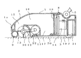
図1から図4はこの発明の実施の形態1を示し、図1は電気掃除機の全体を示す斜視図、図2は電気掃除機本体を示す断面図、図3は電気掃除機本体の内部構造を示す断面図、図4は塵埃を吸引している状態を示す電気掃除機本体の断面図である。
【0011】
図において、1は電気掃除機の本体で、上ケース2と下ケース3により外観を構成している。また、本体1の前端部1aは2枚壁構造になっている。4は本体1の後方に接続された金属または樹脂からなる細長のパイプ、5は本体1に設けられ、本体1に対して上下または左右に回動する連結部で、パイプ4の一端が接続されている。また、パイプ4の他端にはハンドル6が設けられている。7は本体1を走行させるための車輪、8は駆動用の電源スイッチである。9は本体1の底面前方に回動可能に設けられ、起毛等の軟らかい刷子を有する前ブラシで、例えば1mmから5mm程度の起毛で表面が覆われた構成になっている。前ブラシ9は被掃除面、特にフローリングのような硬質素材の床面に当接するように装着されている。
【0012】
10は前ブラシ9の後方に平行して回動可能に設けられ、塵埃を掻き出すための硬い刷子を有する後ブラシで、特に被掃除面が絨毯である場合に当接するように装着されている。後ブラシ10には例えばナイロン素材の毛、またはゴム等の軟質部材で成形されたブレードが設けられている。また、後ブラシ10は回転駆動体11とベルト等の連結手段12を介して連結されている。前ブラシ9と後ブラシ10は、前ブラシ9と後ブラシ10とが当接する接触部13を有するように配置されている。接触部13における回転時の摩擦抵抗は、前ブラシ9と床面との摩擦抵抗より大きくなるように設定されている。
【0013】
14は本体1の後方に内蔵された電動送風機、15は本体1に形成された吸込口で、接触部13の上方に設けられている。また、吸込口15は前ブラシ9と後ブラシ10の接触部13の占める長手方向の長さとほぼ同じ幅で開口している。16は吸込口15と集塵室17とを連結する塵埃を含んだ空気の通路、18は電動送風機14と集塵室17とを仕切るように設けられた通気性のあるフィルター、19は本体1の側面に設けられた排気口、20は本体1の下面に設けられた蓋で、集塵室17に対して開閉可能に支持されている。21は回転駆動体11及び電動送風機14へ電力を送る電池、22は後ブラシ10と平行に、かつ後ブラシ10の後方に設けられたゴム等で形成された遮蔽片である。
【0014】
次に、動作について説明する。
電源スイッチ8をONにすると、回転駆動体11と電動送風機14に通電され、電動送風機14は空気と共に塵埃を吸引し、また、回転駆動体11が連結手段12を介して後ブラシ10を図4に示す矢印A方向(後向き、掃除機本体1の進行方向とは逆の方向)に回転させる。この時、前ブラシ9が後ブラシ10と接触部13で接触しているので、接触による摩擦抵抗により、後ブラシ10の動作に連動して、前ブラシ9が図4に示す矢印B方向(前向き、後ブラシ10と逆方向)に回転する。電動送風機14により吸引された空気は本体1と被清掃面との間、例えば本体1側方(図3に示す矢印C)の隙間から流入し、接触部13の隙間を介して通路16を通って集塵室17へ流れる。そして、フィルター18を通過して電動送風機14に至り、排気口19から本体1外へ排出される。
【0015】
また、被清掃面の塵埃は、前ブラシ9と接触することで前ブラシ9の回転に巻き込まれ、後ブラシ10に弾かれて接触部13へ移動し、遠心力により上部へ放出され、流入した空気の吸引力により、吸込口15から通路16を経て集塵室17に運ばれる。そして、塵埃はフィルター18に阻まれて集塵室17内に集積される。集積された塵埃は蓋20を開けることにより本体1外へ排出される。
【0016】
実施の形態1によれば、前ブラシ9と後ブラシ10とを接触するように装着し、後ブラシ10を進行方向に対して逆方向に回転させ、前ブラシ9を後ブラシ10と反対方向に回転させるようにし、さらに前ブラシ9と被清掃面を当接するように配置したので、後ブラシ13の回転による遠心力によって弾かれた塵埃が外部に押し出されてしまったり、遠心力によって生じた風によって軽い塵埃が、本体1外部に押し出されてしまうことを防止できる。
【0017】
また、前ブラシ9には起毛等の比較的柔らかい刷子を設け、後ブラシ10には前ブラシ9よりも硬い刷子を設けたので、掻き出し効果と、拭き効果を同時に得ることができ、清掃性能が向上する。
【0018】
また、吸込口15を接触部13の上方に設け、前ブラシ9や後ブラシ10の長手方向の長さとほぼ同じ長さで開口しているので、ブラシの遠心力で放出された塵埃を直接、通路16に運ぶことができる。したがって、例えば電動送風機14により発生する吸引力が従来のものと比べて弱くても塵埃を捕獲できる。そのため、電動送風機14の吸引力を抑えることが可能となり、また電動送風機14の回転数を下げることが可能となるので、省エネルギーの効果がある。また電動送風機14の駆動により発生する音も小さくすることができる。さらに、塵埃は後ブラシ10の刷子間を長手方向に移動せず吸込口15に吸引されるので、後ブラシ10に塵埃が絡み付いてしまうことを防ぐことができ、塵埃が吸込口15付近で詰ってしまうことを防止できる。
【0019】
さらに、抵抗の大きい絨毯等を掃除した場合、前ブラシ9の回転数が後ブラシ10の回転数に比べて急速に下がり、接触部13においてスリップする量が増加し、後ブラシ10が前ブラシ9を掻き上げて、前ブラシ9に付着した塵埃や汚れを落とす作用があるため、前ブラシ9の汚染を防ぐことができる。
【0020】
実施の形態2.
図5はこの発明の実施の形態2を示す電気掃除機本体の斜視図、図6は床面に載置した状態を示す要部断面図、図7は絨毯面に載置した状態を示す要部断面図である。図中、実施の形態1と同じ構成には同じ符号を付し説明を省略する。図において、23は前ブラシ9が装着され、回転軸24により本体1に回動可能に設けられたホルダーで、前ブラシ9と後ブラシ10とが接触して実施の形態1同様、接触部13を有する状態で設けられている。そして、本体1が平な床面を掃除する場合は、ホルダー23の自重で、前ブラシ9が被掃除面に接触し、さらに前ブラシ9は後ブラシ10に接触している。そして、前ブラシ9は後ブラシ10の回転に伴ない後ブラシ10の回転方向とは逆向きに回転する。本体1が凹凸のある被掃除面や絨毯を掃除する場合は、凹凸もしくは絨毯の毛によって、前ブラシ9が上方向に押し上げられ、図7に示すように回転軸24を中心にして前ブラシ9がホルダー23ごと上方向に回動する。そして、ホルダー23と前ブラシ9の自重により常に被掃除面へ一定荷重がかかり、前ブラシ9が被清掃面を押している状態となる。また、前ブラシ9が上方向へ押し上げられるので、後ブラシ10とは非接触となり、後ブラシ10への負荷が軽くなる。
【0021】
実施の形態2によれば、絨毯上を掃除する場合、前ブラシ9が上方向へ移動すするので、前ブラシ9または絨毯の摩耗を最小限に抑えることができる。また、前ブラシ9が上方向へ移動すると同時に、後ブラシ10とは非接触となり、前ブラシ9による後ブラシ10への負荷が無くなるため、回転駆動体11への負担が減るので、回転駆動体11が異常な温度上昇を起こしてしまうことを防止できる。また、絨毯から床面へ移動した場合は、再び前ブラシ9が下方へ移動し、後ブラシ10と接触して、後ブラシ10の回転に連動して前ブラシ9が回転する。
【0022】
実施の形態3.
図8はこの発明の実施の形態3を示す電気掃除機本体の斜視図、図9は前ブラシが下がっている状態を示す要部断面図、図10は前ブラシが上がっている状態を示す要部断面図、図11は切替えレバーの動作を示す拡大図である。図中、実施の形態1または2と同一の構成には同じ符号を付し説明を省略する。図において、25は前ブラシ9と後ブラシ10を任意に接触、非接触に切替える切替えレバー、26は切替えレバー25に連動する操作部で、切替えレバー25をスライドさせた時にホルダー23の裏面に突設された突部27と接触するように設けられている。図11(a)(b)に示すとおり、切替えレバー25を矢印D方向へ移動させると、操作部26が切替えレバー25と共に移動し、突部27に接触してホルダー23を矢印E方向へ持ち上げる。この際に、前ブラシ9も連動してE方向へ持上げられて、図10に示すとおり、前ブラシ9と後ブラシ10が非接触となるので、回転駆動体11への負担を和らげることができる。また、前ブラシ9または絨毯の摩耗を最小限に抑えることができる。
【0023】
実施の形態4.
図12はこの発明の実施の形態4を示す電気掃除機本体の要部断面図、図13はブラシの動作を示す拡大図であり、図中、実施の形態1と同一の構成には同じ符号を付し説明を省略する。実施の形態4では、前ブラシ9が本体1の前端部1aの前壁28より前方へはみ出すか、または前ブラシ9の周縁が前壁28とほぼ同じ位置になるように前ブラシ9を設置したものを示す。また、実施の形態1同様、前ブラシ9は後ブラシ10と接するように設けられているので、図13に示すとおり、後ブラシ10が矢印A方向に回転するのと連動して、前ブラシ9は後ブラシ10と逆方向、矢印B方向に回転する。この構成により、前ブラシ9及び後ブラシ10が回転している状態で壁際、家具等に本体1を近づけると、前壁28が壁に接触すると同時か、それより前に前ブラシ9が壁(または家具等)と床面にできる角に溜まった塵埃を掻き出すことができる。また、前ブラシ9が前壁28より前方へはみ出すように設置されている場合は、壁、家具等に当てた時、前ブラシ9の周縁部が壁、家具等に当り、前壁28は壁、家具等に当らないので、壁、家具等の傷付きを防止することもできる。
【0024】
実施の形態5.
図14はこの発明の実施の形態5を示す電気掃除機本体の拡大断面図である。図中、実施の形態1と同一の構成には同じ符号を付し説明を省略する。図において、29は電気掃除機本体1前端部1aの一部である前下部で、前壁30と前ブラシ9の周縁部に沿うように形成された内壁31とを有している。前壁30は前ブラシ9の上半分部分を覆うように設けられ、内壁31は前ブラシ9との隙間が1mm以内となるように設けられている。また、実施の形態1同様、前ブラシ9は後ブラシ10と接するように設けられているので、後ブラシ10が矢印A方向に回転するのと連動して、前ブラシ9は後ブラシ10と逆方向、矢印B方向に回転する。この構成により、前ブラシ9と後ブラシ10の回転により直径1mm以上の塵埃は接触部13を介して吸込口15から吸引され、直径1mm以下の塵埃の一部は前ブラシ9と内壁31との間を通り、下方のF方向へ放出され再度、前ブラシ9によってかき込まれる。したがって、前ブラシ9の上部に前下部29を設けたので、特に細かい固形の塵埃等を前方に弾き出すこともなく、確実に塵埃を捕獲することができ、また、スムーズに前ブラシ9を回転させることができる。
【0025】
なお、前ブラシ9と後ブラシ10とのサイズの関係を、前ブラシ9の径より後ブラシ10の径を大きくして前ブラシ9の起毛と後ブラシ10とが接するように構成してもよい。この構成により、後ブラシ10の回転動作に連動して、前ブラシ9は後ブラシ10とは逆方向に回転する。また、前ブラシ9の径の方が小さいので、後ブラシ10よりも高速に回転する。そして、この状態で被掃除面に載置して掃除すると、被掃除面との摩擦抵抗により、前ブラシ9は減速され、接触部13において後ブラシ10との間でスリップを起こし、後ブラシ10の回転よりも前ブラシ9の回転の方がより減速する。このスリップにより、前ブラシ9に付着した塵埃を後ブラシ10が掻き上げて、前ブラシ9の汚れを落とすことができる。また、前ブラシ9が小径であればある程、壁と床との角に溜まる塵埃へ起毛が届きやすくなるという効果もある。
【0026】
また、前ブラシ9の径より後ブラシ10の径を小さくして前ブラシ9と後ブラシ10と接するように構成してもよい。この構成により、後ブラシ10の回転動作に連動して、前ブラシ9は後ブラシ10とは逆方向に回転する。また、前ブラシ9の径の方が大きいので、後ブラシ10よりも低速に回転する。そして、この状態で被掃除面に載置して掃除をすると、前ブラシ9の減速は後ブラシ10の径を大きくした場合よりも大きくなり、後ブラシ10との間でのスリップが多くなる。したがって、前ブラシ9に付着した塵埃を後ブラシ10の毛やへらが掻き上げて、前ブラシ9の汚れを落とす性能をより向上させることができる。また、前ブラシ9の表面積が大きく、回転数も少ないことから摩耗も少なく、寿命が長くなるという効果がある。
【0027】
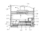
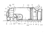
実施の形態6.
図15はこの発明の実施の形態6を示す電気掃除機本体の内部構造を示す断面図、図16は塵埃を吸引している状態を示す電気掃除機本体の断面図である。図中、実施の形態1と同様の構成には同じ符号を付し説明を省略する。図において、32は通路16と遮断された排気風路であり、図15に示すとおり、電動送風機14から排出された空気を回転駆動体11へ導くための開口部33、34が設けられている。35は後ブラシ10の後方で遮蔽片22より前に形成された排出口で、開口部33、34と連通し、排気風路32を形成している。この構成により、電動送風機14で吸引された空気の全てもしくは一部が、排気風路32を通って回転駆動体11を冷却しながら排出口35を通って、後ブラシ10と遮蔽片22の間に吹き付ける。この吹き付け風によって、後ブラシ10では掻き出しきれなかった、後ブラシ10と遮蔽片22の間の塵埃を浮き出させて、後ブラシ10の方へ移動させて吸塵させるので、塵埃が残ることを防ぐことができる。また、排気の量が少なくなるか、全く外部へは出なくなり、被掃除面の塵埃の巻き上げを抑えることができる。
【0028】
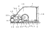
実施の形態7.
図17はこの発明の実施の形態7を示す電気掃除機本体の断面図、図18は図17に示すF−F断面図、図19は塵埃の吸引状態を示す断面図である。36は吸込口15の上方に設けた風路形成部であり、吸込口15に沿って、吸込口15とほぼ同じ幅で設置されている。37は風路形成部36の後方に形成されて集塵室17と連通する絞り口であり、通路16の開口面積より小さい開口面積で開口している。風路形成部36は絞り口37に近づくにつれて高さが高くなるように傾斜天井38を有し、絞り口37に近づくにつれて、開口面積が大きくなるように構成されている。この構成により、図19に示すように、前ブラシ9と後ブラシ10によって上方へ掻き上げられた塵埃のうち、絞り口37の正面に弾き出された塵埃は、絞り口37より吸引されて集塵室17にとり込まれる。また、絞り口37正面に直接弾き上げられない塵埃は、傾斜天井38に当たり、角度を絞り口37側へ変えて落下し、更に前ブラシ9と後ブラシ10によって再度上方へ弾き上げられる。この動作を塵埃が絞り口37へ到達するまで繰り返されて絞り口37から吸引される。これにより、前ブラシ9及び後ブラシ10と傾斜天井38との間の空間を使って、塵埃が絞り口37へ移動するので、紙屑のような大きな塵埃も通ることができる。更に、絞り口37により吸込口15と通路16との間で1度断面積が絞られるので、吸引速度も速めることが可能となり、前ブラシ9と後ブラシ10によって弾き上げられた塵埃を、集塵室17へ移動する力を増加させることができる。したがって、集塵力を向上させることが可能となる。
【0029】
【発明の効果】
この発明は、以上のように構成されているので、次に示すような効果がある。
【0030】
本発明によれば、前後のブラシに挟み込まれた塵埃を、遠心力で直接吸込口へ運ぶことができる。また、後ブラシの回転による遠心力によって弾かれた塵埃が、外部に押し出されてしまったり、遠心力によって生まれた風により、塵埃が外部に押し出されてしまうことを防止できるという効果がある。また、壁や家具等の壁際まできれいに掃除ができるという効果がある。また、前ブラシと後ブラシによって弾き上げられた塵埃を、集塵室へ移動する力を増加させることができ、集塵力を向上させることが可能となる。
【0031】
また、吸込口は、前ブラシと後ブラシの接触部の長手方向の幅に対して同じ幅で開口しているので、接触部により挟み込まれた塵埃をそのまま吸込口へ運ぶことができ、吸塵性能がよい。
【0032】
また、前ブラシには床面を拭くための起毛等の軟らかい刷子を設け、後ブラシには絨毯から塵埃を掻き出すための前ブラシよりも硬い刷子が設けられているので、掻き出し効果と、乾拭き効果を同時に得ることができる。
【0033】
また、前ブラシを回動可能に支持するとともに、掃除機本体に対して上下動可能に支持する支持部材を設け、支持部材は、前ブラシを掃除機本体に対して上下動させると共に、前ブラシの上下動に応じて前ブラシと後ブラシとの非接触、接触を切替えるので、前ブラシの摩耗、被清掃面の摩耗を抑えることができる。また、前ブラシによる後ブラシへの負荷がなくなるため、例えば後ブラシを回転させている回転駆動体への負担が減り、回転駆動体が異常な温度上昇を起こしてしまうことを防止することが可能である。
【図面の簡単な説明】
【図1】 この発明の実施の形態1を示す電気掃除機全体の斜視図である。
【図2】 この発明の実施の形態1を示す電気掃除機本体の断面図である。
【図3】 この発明の実施の形態1を示す電気掃除機本体の内部構造を示す横断面図である。
【図4】 この発明の実施の形態1を示す電気掃除機本体の断面図である。
【図5】 この発明の実施の形態2を示す電気掃除機本体の斜視図である。
【図6】 この発明の実施の形態2を示す電気掃除機を床面に載置した状態を示す要部断面図である。
【図7】 同、絨毯面に載置した状態を示す要部断面図である。
【図8】 この発明の実施の形態3を示す電気掃除機本体の斜視図である。
【図9】 前ブラシが下がっている状態を示す要部断面図である。
【図10】 前ブラシが上がっている状態を示す要部断面図である。
【図11】 切替えレバーの動作を示す拡大図である。
【図12】 この発明の実施の形態4を示す電気掃除機本体の要部断面図である。
【図13】 同、ブラシの動作を示す拡大図である。
【図14】 この発明の実施の形態5を示す電気掃除機本体の拡大断面図である。
【図15】 この発明の実施の形態6を示す電気掃除機本体の内部構造を示す断面図である。
【図16】 同、電気掃除機の塵埃を吸引している状態を示す電気掃除機本体の断面図である。
【図17】 この発明の実施の形態7を示す電気掃除機本体の断面図である。
【図18】 図17に示すF−F断面図である。
【図19】 同、電気掃除機の塵埃の吸引状態を示す断面図である。
【図20】 従来の電気掃除機を示す平面図である。
【図21】 従来の電気掃除機の吸込口室を示す断面図である。
【符号の説明】
1 本体、2 上ケース、3 下ケース、4 パイプ、5 連結部、
6 ハンドル、7 車輪、8 電源スイッチ、9 前ブラシ、10 後ブラシ、
11 回転駆動体、12 連結手段、13 接触部、14 電動送風機、
15 吸込口、16 風路、17 集塵室、18 フィルター、19 排気口、
20 蓋、21 電池、22 遮蔽片、23 ホルダー、24 回転軸、
25 切替レバー、26 操作部、27 突部、28 前壁、29 前下部、
30 前壁、31 内壁、32 排気風路、33 開口部、34 開口部、
35 排気口、36 風路形成部、37 絞り口、38 傾斜天井。[0001]
BACKGROUND OF THE INVENTION
The present invention relates to a vacuum cleaner using a rotating brush.
[0002]
[Prior art]
FIG. 20 is a plan view showing a conventional vacuum cleaner disclosed in, for example, Japanese Utility Model Laid-Open No. 57-181249, and FIG. 21 is a cross-sectional view showing the suction port chamber. The conventional vacuum cleaner is provided with a
[0003]
[Problems to be solved by the invention]
However, in the conventional vacuum cleaner, when the
[0004]
The present invention has been made to solve the above-described problems, and the rear brush is rotated in the direction opposite to the traveling direction of the cleaner body, and is scraped up from above the contact portion between the rear brush and the front brush. An object of the present invention is to provide a vacuum cleaner with good dust absorption performance by sucking dust.
[Means for Solving the Problems]
An electric vacuum cleaner according to the present invention includes a front brush provided in front of a vacuum cleaner main body, a rear brush provided in contact with the front brush behind the front brush, and the front brush and the rear brush. A suction port provided above the contact portion so as to face the contact portion, the rear brush rotates in a direction opposite to a traveling direction of the cleaner body, and the front brush rotates the rear brush. The front brush rotates in the direction opposite to the rear brush, and the front peripheral portion of the front brush is part of the suction port at the front end of the cleaner body with respect to the traveling direction of the cleaner body. It is installed so as to protrude forward from the inside of the wall to be formed, and an air passage forming member is provided above the suction port, and the air passage forming member has an opening having a smaller opening area than the suction port at the rear of the cleaner body. Communicates with the dust collection chamber The air passage forming member has an inclined portion on the ceiling of the air passage forming member so that the area of the passage increases as it approaches the opening, and the opening out of the dust scraped upward by the front brush and the rear brush. Dust ejected from the front of the front is sucked through the opening and taken into the dust collection chamber, dust that cannot be flipped up to the front of the opening is applied to the inclined portion and changed to the opening side, and dropped, and the front brush and The operation of flipping up again by the rear brush is repeated until dust reaches the opening .
[0006]
Moreover, the said suction inlet is opened with the substantially same width | variety with respect to the width | variety of the longitudinal direction of the said contact part of the said front brush and the said back brush.
[0007]
Further, the front brush is provided with a soft brush such as a raised brush for wiping the floor surface, and the rear brush is provided with a brush harder than the front brush for scraping dust from the carpet.
[0008]
In addition, the front brush is rotatably supported, and a support member is provided to support the vacuum cleaner main body so that the front brush can move up and down. The support member has the front brush upward with respect to the vacuum cleaner main body. the non-contact the rear brush and the front brush by moving, but to switch to contact the rear brush and the front brush by moving down against the cleaner body to the front brush.
[0009]
Further, the rear brush is driven by a rotary driving body.
[0010]
DETAILED DESCRIPTION OF THE INVENTION
1 to 4 show a first embodiment of the present invention, FIG. 1 is a perspective view showing the entire vacuum cleaner, FIG. 2 is a cross-sectional view showing the main body of the vacuum cleaner, and FIG. 3 is an internal view of the main body of the vacuum cleaner. Sectional drawing which shows a structure, FIG. 4 is sectional drawing of the vacuum cleaner main body which shows the state which is attracting | sucking dust.
[0011]
In the figure,
[0012]
[0013]
14 is an electric blower built in the back of the
[0014]
Next, the operation will be described.
When the
[0015]
Further, the dust on the surface to be cleaned is caught in the rotation of the
[0016]
According to the first embodiment, the
[0017]
Further, since the
[0018]
Further, the
[0019]
Further, when a carpet having high resistance is cleaned, the rotational speed of the
[0020]
5 is a perspective view of a main body of a vacuum
[0021]
According to the second embodiment, when cleaning the carpet, the
[0022]
8 is a perspective view of an electric vacuum cleaner main
[0023]
12 is a cross-sectional view of the main part of the electric vacuum cleaner main body showing the fourth embodiment of the present invention, and FIG. 13 is an enlarged view showing the operation of the brush. In the figure, the same reference numerals are used for the same components as in the first embodiment. The description is omitted. In the fourth embodiment, the
[0024]
FIG. 14 is an enlarged cross-sectional view of a vacuum cleaner
[0025]
The size relationship between the
[0026]
Further, the diameter of the
[0027]
15 is a cross-sectional view showing the internal structure of a vacuum cleaner body according to
[0028]
FIG. 17 is a cross-sectional view of an electric vacuum cleaner main
[0029]
【The invention's effect】
Since the present invention is configured as described above, the following effects can be obtained.
[0030]
According to the present invention, dust sandwiched between the front and rear brushes can be directly conveyed to the suction port by centrifugal force. In addition, there is an effect that dust repelled by the centrifugal force generated by the rotation of the rear brush can be prevented from being pushed out and the dust can be prevented from being pushed out by the wind generated by the centrifugal force. In addition, there is an effect that the wall and furniture can be cleaned cleanly. Moreover, the force which moves the dust flipped up by the front brush and the rear brush to the dust collecting chamber can be increased, and the dust collecting force can be improved.
[0031]
In addition, since the suction port opens with the same width as the longitudinal width of the contact portion of the front brush and the rear brush, the dust sandwiched by the contact portion can be directly carried to the suction port, and the dust absorption performance Is good.
[0032]
In addition, the front brush is provided with soft brushes such as raising brushes for wiping the floor surface, and the rear brush is provided with a harder brush than the front brush for scraping dust from the carpet. Can be obtained at the same time.
[0033]
In addition, a support member that supports the front brush so as to be rotatable and is supported so as to be movable up and down with respect to the cleaner body is provided. The support member moves the front brush up and down relative to the cleaner body, and the front brush noncontact between the front brush and rear brush according to the vertical movement, so switches the contact, it can be pre-brush wear, obtaining suppress the wear of the surface to be cleaned. In addition, since the load on the rear brush by the front brush is eliminated, for example, the burden on the rotary drive that rotates the rear brush is reduced, and it is possible to prevent the rotary drive from causing an abnormal temperature increase. It is.
[Brief description of the drawings]
FIG. 1 is a perspective view of an entire electric vacuum cleaner showing a first embodiment of the present invention.
FIG. 2 is a cross-sectional view of the electric vacuum cleaner main
FIG. 3 is a transverse sectional view showing the internal structure of the electric vacuum cleaner main
FIG. 4 is a cross-sectional view of the electric vacuum cleaner main
FIG. 5 is a perspective view of an electric vacuum cleaner main
FIG. 6 is a cross-sectional view of a main part showing a state where a vacuum cleaner according to
FIG. 7 is a cross-sectional view of the main part showing the state of being placed on the carpet surface.
FIG. 8 is a perspective view of a vacuum cleaner main
FIG. 9 is a cross-sectional view of a main part showing a state where a front brush is lowered.
FIG. 10 is a cross-sectional view of a main part showing a state where a front brush is raised.
FIG. 11 is an enlarged view showing the operation of the switching lever.
FIG. 12 is a cross-sectional view of a main part of a vacuum cleaner main
FIG. 13 is an enlarged view showing the operation of the brush.
FIG. 14 is an enlarged cross-sectional view of a vacuum cleaner body showing a fifth embodiment of the present invention.
FIG. 15 is a cross-sectional view showing an internal structure of a vacuum cleaner body according to
FIG. 16 is a cross-sectional view of the main body of the vacuum cleaner showing a state in which dust is sucked from the vacuum cleaner.
FIG. 17 is a cross-sectional view of a main body of a vacuum
18 is a cross-sectional view taken along line FF shown in FIG.
FIG. 19 is a cross-sectional view showing a dust suction state of the electric vacuum cleaner.
FIG. 20 is a plan view showing a conventional electric vacuum cleaner.
FIG. 21 is a cross-sectional view showing a suction port chamber of a conventional electric vacuum cleaner.
[Explanation of symbols]
1 body, 2 upper case, 3 lower case, 4 pipe, 5 connecting part,
6 handle, 7 wheels, 8 power switch, 9 front brush, 10 rear brush,
11 rotation drive body, 12 connection means, 13 contact part, 14 electric blower,
15 suction port, 16 air passages, 17 dust collection chamber, 18 filter, 19 exhaust port,
20 lid, 21 battery, 22 shielding piece, 23 holder, 24 rotation axis,
25 switching lever, 26 operation part, 27 protrusion, 28 front wall, 29 front lower part,
30 front wall, 31 inner wall, 32 exhaust air duct, 33 opening, 34 opening,
35 Exhaust port, 36 Air channel formation part, 37 Restriction port, 38 Inclined ceiling.
Claims (5)
前記吸込口の上方に風路形成部材を設け、前記風路形成部材は、前記吸込口より開口面積が小さい開口を前記掃除機本体の後方に設けた集塵室と連通するように形成し、前記風路形成部材の天井には前記開口に近づくにつれて通路面積が大きくなるように傾斜部を有し、前記前ブラシと前記後ブラシによって上方へ掻き上げた塵埃のうち、前記開口の正面に弾き出した塵埃を前記開口より吸引して集塵室にとり込み、前記開口正面に弾き上げられない塵埃を前記傾斜部に当てて角度を前記開口側へ変えて落下させ、前記前ブラシと前記後ブラシによって再度上方へ弾き上げる動作を、塵埃が前記開口へ到達するまで繰り返させることを特徴とする電気掃除機。A front brush provided in front of the cleaner body, a rear brush provided in contact with the front brush behind the front brush, and the contact portion above the contact portion of the front brush and the rear brush. The rear brush rotates in a direction opposite to the direction of travel of the cleaner body, and the front brush is interlocked with the rotation of the rear brush. The front brush rotates in the opposite direction, and the front peripheral portion protrudes forward from the inside of the wall forming a part of the suction port at the front end of the cleaner body with respect to the traveling direction of the cleaner body. is installed so that,
An air passage forming member is provided above the suction port, and the air passage forming member is formed to communicate with a dust collection chamber provided at the rear of the cleaner body with an opening area smaller than the suction port. The ceiling of the air passage forming member has an inclined portion so that the passage area increases as it approaches the opening, and of the dust scraped upward by the front brush and the rear brush, it projects to the front of the opening. The dust collected from the opening is sucked into the dust collection chamber, and the dust that cannot be flipped up to the front of the opening is applied to the inclined portion to change the angle toward the opening, and is dropped by the front brush and the rear brush. An electric vacuum cleaner characterized by repeating the operation of flipping up again until dust reaches the opening .
Priority Applications (1)
| Application Number | Priority Date | Filing Date | Title |
|---|---|---|---|
| JP2000362881A JP3858217B2 (en) | 2000-11-29 | 2000-11-29 | Vacuum cleaner |
Applications Claiming Priority (1)
| Application Number | Priority Date | Filing Date | Title |
|---|---|---|---|
| JP2000362881A JP3858217B2 (en) | 2000-11-29 | 2000-11-29 | Vacuum cleaner |
Related Child Applications (1)
| Application Number | Title | Priority Date | Filing Date |
|---|---|---|---|
| JP2006190293A Division JP2006312066A (en) | 2006-07-11 | 2006-07-11 | Vacuum cleaner |
Publications (3)
| Publication Number | Publication Date |
|---|---|
| JP2002165731A JP2002165731A (en) | 2002-06-11 |
| JP2002165731A5 JP2002165731A5 (en) | 2004-08-19 |
| JP3858217B2 true JP3858217B2 (en) | 2006-12-13 |
Family
ID=18834080
Family Applications (1)
| Application Number | Title | Priority Date | Filing Date |
|---|---|---|---|
| JP2000362881A Expired - Lifetime JP3858217B2 (en) | 2000-11-29 | 2000-11-29 | Vacuum cleaner |
Country Status (1)
| Country | Link |
|---|---|
| JP (1) | JP3858217B2 (en) |
Families Citing this family (23)
| Publication number | Priority date | Publication date | Assignee | Title |
|---|---|---|---|---|
| US6956348B2 (en) | 2004-01-28 | 2005-10-18 | Irobot Corporation | Debris sensor for cleaning apparatus |
| JP4621544B2 (en) * | 2005-06-08 | 2011-01-26 | 株式会社東芝 | Suction port and vacuum cleaner provided with the same |
| JP4585387B2 (en) * | 2005-06-17 | 2010-11-24 | 花王株式会社 | Cleaning tool |
| KR100757383B1 (en) | 2006-10-11 | 2007-09-11 | 삼성광주전자 주식회사 | Nozzle assembly for vacuum cleaner |
| JP4958572B2 (en) * | 2007-02-07 | 2012-06-20 | パナソニック株式会社 | Vacuum cleaner suction and vacuum cleaner |
| CN103549921B (en) | 2008-03-17 | 2017-01-11 | 伊莱克斯家用产品有限公司 | Agitator with Cleaning Features |
| US10117553B2 (en) | 2008-03-17 | 2018-11-06 | Aktiebolaget Electrolux | Cleaning nozzle for a vacuum cleaner |
| US9820626B2 (en) | 2008-03-17 | 2017-11-21 | Aktiebolaget Electrolux | Actuator mechanism for a brushroll cleaner |
| KR101473793B1 (en) * | 2008-03-19 | 2014-12-17 | 삼성전자주식회사 | Brush assembly and vacuum cleaner having the same |
| KR101525597B1 (en) | 2008-11-03 | 2015-06-02 | 삼성전자주식회사 | Suction nozzle apparatus and vacuum cleaner having the same |
| JP5054168B2 (en) * | 2010-08-02 | 2012-10-24 | 株式会社東芝 | Suction port body and electric vacuum cleaner provided with the same |
| JP2014534016A (en) | 2011-10-26 | 2014-12-18 | アクティエボラゲット エレクトロラックス | Cleaning the vacuum cleaner nozzle |
| US9993847B2 (en) | 2012-02-02 | 2018-06-12 | Aktiebolaget Electrolux | Cleaning arrangement for a nozzle of a vacuum cleaner |
| JP5457485B2 (en) * | 2012-03-02 | 2014-04-02 | アイロボット コーポレイション | Cleaning device with debris sensor |
| JP5881495B2 (en) * | 2012-03-26 | 2016-03-09 | 株式会社東芝 | Vacuum cleaner and its suction port |
| US10045672B2 (en) | 2012-12-21 | 2018-08-14 | Aktiebolaget Electrolux | Cleaning arrangement for a rotatable member of a vacuum cleaner, cleaner nozzle, vacuum cleaner and cleaning unit |
| WO2014129806A1 (en) * | 2013-02-22 | 2014-08-28 | Lee Chun-Woo | Suction body |
| KR101435600B1 (en) | 2013-03-07 | 2014-08-28 | 주식회사 칼라카나 | floor suction fitting |
| KR101516944B1 (en) * | 2013-02-26 | 2015-05-15 | 주식회사 스프링 | cleaning apparatus |
| US9072416B2 (en) | 2013-03-15 | 2015-07-07 | Aktiebolaget Electrolux | Vacuum cleaner agitator cleaner with brushroll lifting mechanism |
| JP2014212846A (en) * | 2013-04-23 | 2014-11-17 | 日立アプライアンス株式会社 | Vacuum cleaner and suction tool |
| EP3289946B1 (en) | 2013-05-02 | 2021-03-31 | Aktiebolaget Electrolux | Cleaning nozzle for vacuum cleaner |
| KR101514201B1 (en) * | 2013-11-28 | 2015-04-23 | (주)동부로봇 | Robot cleaner having triple rotating part |
-
2000
- 2000-11-29 JP JP2000362881A patent/JP3858217B2/en not_active Expired - Lifetime
Also Published As
| Publication number | Publication date |
|---|---|
| JP2002165731A (en) | 2002-06-11 |
Similar Documents
| Publication | Publication Date | Title |
|---|---|---|
| JP3858217B2 (en) | Vacuum cleaner | |
| JP2006312066A (en) | Vacuum cleaner | |
| JP4672553B2 (en) | Suction port and vacuum cleaner | |
| GB2251178A (en) | Vacuum cleaner | |
| JP3937405B2 (en) | Vacuum cleaner suction tool and vacuum cleaner provided with the same | |
| JP2000166826A (en) | Vacuum cleaner | |
| KR20200007832A (en) | Cleaner with coaming unit to remove rubbish from cleaning rollers | |
| JP3813811B2 (en) | Suction port and vacuum cleaner | |
| KR100747137B1 (en) | Vaccum clear | |
| JP3830961B2 (en) | Suction port and vacuum cleaner | |
| KR20070016420A (en) | Suction Unit for Cleaner | |
| JP3815595B2 (en) | Vacuum cleaner and its suction port | |
| JP3749056B2 (en) | Suction port and vacuum cleaner | |
| JP2000126097A (en) | Vacuum cleaner and suction port body therefor | |
| KR101108047B1 (en) | Robot Cleaner | |
| JP2004065915A (en) | Suction port body and vacuum cleaner | |
| JPH02114Y2 (en) | ||
| JP2000037327A (en) | Floor nozzle for vacuum cleaner | |
| JP3815610B2 (en) | Vacuum cleaner and its suction port | |
| JP3603994B2 (en) | Upright type vacuum cleaner | |
| JPS6151886B2 (en) | ||
| JP3501958B2 (en) | Suction port body and vacuum cleaner | |
| JP3558202B2 (en) | Vacuum cleaner and its suction body | |
| JP4028784B2 (en) | Suction port and vacuum cleaner | |
| JPH0873173A (en) | Oil pan cleaning device for passenger conveyor |
Legal Events
| Date | Code | Title | Description |
|---|---|---|---|
| RD01 | Notification of change of attorney |
Free format text: JAPANESE INTERMEDIATE CODE: A7421 Effective date: 20040806 |
|
| RD03 | Notification of appointment of power of attorney |
Free format text: JAPANESE INTERMEDIATE CODE: A7423 Effective date: 20041224 |
|
| RD04 | Notification of resignation of power of attorney |
Free format text: JAPANESE INTERMEDIATE CODE: A7424 Effective date: 20050308 |
|
| A977 | Report on retrieval |
Free format text: JAPANESE INTERMEDIATE CODE: A971007 Effective date: 20050318 |
|
| A131 | Notification of reasons for refusal |
Free format text: JAPANESE INTERMEDIATE CODE: A131 Effective date: 20051206 |
|
| A521 | Written amendment |
Free format text: JAPANESE INTERMEDIATE CODE: A523 Effective date: 20060106 |
|
| RD04 | Notification of resignation of power of attorney |
Free format text: JAPANESE INTERMEDIATE CODE: A7424 Effective date: 20060202 |
|
| A131 | Notification of reasons for refusal |
Free format text: JAPANESE INTERMEDIATE CODE: A131 Effective date: 20060516 |
|
| A521 | Written amendment |
Free format text: JAPANESE INTERMEDIATE CODE: A523 Effective date: 20060711 |
|
| TRDD | Decision of grant or rejection written | ||
| A01 | Written decision to grant a patent or to grant a registration (utility model) |
Free format text: JAPANESE INTERMEDIATE CODE: A01 Effective date: 20060829 |
|
| A61 | First payment of annual fees (during grant procedure) |
Free format text: JAPANESE INTERMEDIATE CODE: A61 Effective date: 20060907 |
|
| R150 | Certificate of patent or registration of utility model |
Ref document number: 3858217 Country of ref document: JP Free format text: JAPANESE INTERMEDIATE CODE: R150 Free format text: JAPANESE INTERMEDIATE CODE: R150 |
|
| FPAY | Renewal fee payment (event date is renewal date of database) |
Free format text: PAYMENT UNTIL: 20090929 Year of fee payment: 3 |
|
| FPAY | Renewal fee payment (event date is renewal date of database) |
Free format text: PAYMENT UNTIL: 20100929 Year of fee payment: 4 |
|
| FPAY | Renewal fee payment (event date is renewal date of database) |
Free format text: PAYMENT UNTIL: 20110929 Year of fee payment: 5 |
|
| FPAY | Renewal fee payment (event date is renewal date of database) |
Free format text: PAYMENT UNTIL: 20110929 Year of fee payment: 5 |
|
| FPAY | Renewal fee payment (event date is renewal date of database) |
Free format text: PAYMENT UNTIL: 20120929 Year of fee payment: 6 |
|
| FPAY | Renewal fee payment (event date is renewal date of database) |
Free format text: PAYMENT UNTIL: 20130929 Year of fee payment: 7 |
|
| R250 | Receipt of annual fees |
Free format text: JAPANESE INTERMEDIATE CODE: R250 |
|
| R250 | Receipt of annual fees |
Free format text: JAPANESE INTERMEDIATE CODE: R250 |
|
| R250 | Receipt of annual fees |
Free format text: JAPANESE INTERMEDIATE CODE: R250 |
|
| R250 | Receipt of annual fees |
Free format text: JAPANESE INTERMEDIATE CODE: R250 |
|
| R250 | Receipt of annual fees |
Free format text: JAPANESE INTERMEDIATE CODE: R250 |
|
| R250 | Receipt of annual fees |
Free format text: JAPANESE INTERMEDIATE CODE: R250 |
|
| EXPY | Cancellation because of completion of term |