JP3848540B2 - Parapet waterproof structure - Google Patents
Parapet waterproof structure Download PDFInfo
- Publication number
- JP3848540B2 JP3848540B2 JP2001028668A JP2001028668A JP3848540B2 JP 3848540 B2 JP3848540 B2 JP 3848540B2 JP 2001028668 A JP2001028668 A JP 2001028668A JP 2001028668 A JP2001028668 A JP 2001028668A JP 3848540 B2 JP3848540 B2 JP 3848540B2
- Authority
- JP
- Japan
- Prior art keywords
- wall panel
- waterproof
- parapet
- heat insulating
- insulating material
- Prior art date
- Legal status (The legal status is an assumption and is not a legal conclusion. Google has not performed a legal analysis and makes no representation as to the accuracy of the status listed.)
- Expired - Fee Related
Links
Images
Description
【0001】
【発明の属する技術分野】
本発明は、鉄骨系住宅におけるパラペットの防水構造に関するものである。
【0002】
【従来の技術】
従来、複数個の中空部が上下方向に貫通して形成されるとともに、裏面側の所定位置にナット金具が予め配設された押出成形セメント板からなる外壁パネルが知られている。このような外壁パネルを用いて鉄骨系住宅の外壁を形成する場合、下階の鉄骨梁に下部取付部材を固定するとともに、上階の鉄骨梁に上部取付部材を固定し、外壁パネルを下部取付部材および上部取付部材にわたって固定するようにしている(例えば、出願人の出願に係る特開2000−87483号公報参照)。
【0003】
【発明が解決しようとする課題】
ところで、最上階の外壁パネルについては、最上階の鉄骨梁の上方に延設されてパラペットに形成されている。この場合、屋上を防水するため、防水シートを屋上の床下地材と外壁パネルにわたって貼着するともに、外壁パネルの上端面にパラペット笠木を取り付けて防水するようにしている。このため、パラペット笠木および該パラペット笠木を取り付けるための部品やその前作業が必要となり、作業が複雑になるとともに、コストがかさむという問題があった。
【0004】
本発明は、このような問題点に鑑みてなされたものであり、パラペットを含む屋上の防水施工を簡単かつ安価に行うことのできるパラペットの防水構造を提供するものである。
【0005】
【課題を解決するための手段】
本発明は、最上階の鉄骨梁を越えて上方に延設された外壁パネルと、外壁パネルの上端面および裏面上端縁部を覆って固定されたパラペット防水下地レールと、外壁パネルの表面上端縁部およびパラペット防水下地レールにおける外壁パネルの上端面側を覆って固定された笠木鋼板と、屋上の床下地材上に敷設されて側端面が外壁パネルの裏面に突き合わされた断熱材と、外壁パネルと断熱材との隅角部もしくは外壁パネルと断熱材上に敷設されて側端面が外壁パネルの裏面に突き合わされた不燃ボードとの隅角部に配設された補強鋼板と、断熱材もしくは不燃ボード上に敷設され、断熱材もしくは不燃ボードの側端縁を越えた延長部を有する防水シートと、から構成され、防水シートが補強鋼板に溶着されてその延長部が外壁パネルの裏面に沿って立ち上げられるとともに、防水下地レールおよび笠木鋼板における外壁パネルの上端面側を覆って笠木鋼板に溶着されていることを特徴とするものである。
【0006】
本発明によれば、外壁パネルの上端部にパラペット防水下地レールおよび笠木鋼板を固定するとともに、屋上の床下地材上に断熱材を敷設し、外壁パネルと断熱材との隅角部または外壁パネルと断熱材上に敷設された不燃ボードとの隅角部に補強鋼板を配設し、防水シートを断熱材もしくは不燃ボード上に敷設して補強鋼板に溶着し、防水シートの延長部を外壁パネルの裏面に沿って立ち上げるとともに、パラペット防水下地レールおよび笠木鋼板まで巻き回して笠木鋼板に溶着するという簡単な作業により、パラペット笠木などを用いることなくパラペットを含む屋上の防水施工を行うことができる。
【0007】
【発明の実施の形態】
以下、本発明のパラペットの防水構造の実施の形態について図面に基づいて説明する。
【0008】
図1には、本発明のパラペットの防水構造の一実施形態が示されている。
【0009】
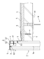
このパラペットの防水構造は、最上階の鉄骨梁Hを越えて上方に一定長さ延設された外壁パネル1と、外壁パネル1の上端面および裏面側上端縁部を覆って固定されたパラペット防水下地レール2と、外壁パネル1の表面側上端縁部およびパラペット防水下地レール2における外壁パネル1の上端面側を覆って固定された笠木鋼板3と、最上階の鉄骨梁Hに設けられる床下地材Y、例えば、ALC床材上に敷設された断熱材4と、断熱材4上に敷設された不燃ボード5と、不燃ボード5上に敷設され、不燃ボード5の側端縁を越えた延長部を有する防水シート6と、から構成されている。
【0010】
ここで、最上階の鉄骨梁Hは、小屋梁であって、断面H字状の形鋼が採用されている。
【0011】
また、床下地材Yは、屋上の床下地を構成するものであり、最上階の鉄骨梁Hの上フランジh1の上面にわたって載置され、適宜固定されている。
【0012】
外壁パネル1は、押出成形セメント板であって、上下方向に貫通する複数個の中空部1aが形成されている。そして、外壁パネル1の表面には、詳細には図示しないが、加飾模様、例えば、縦方向および横方向にそれぞれ設定間隔をおいた複数本の横溝と縦溝からなる目地パターンが形成されている。
【0013】
パラペット防水下地レール2は、断面L字状の鋼板製下地レール本体21と、下地レール本体21の水平部の裏面に設定間隔をおいて溶接された断面コ字状の複数個の取付板22と、からなり、下地レール本体21をその垂直部が外壁パネル1の裏面側上端部に沿うように水平部を外壁パネル1の上端面に載置した際、取付板22が外壁パネル1の各中空部1aに差し込まれるように、大きさと取付位置が設定されている。そして、外壁パネル1の中空部1aに差し込まれたパラペット防水下地レール2の取付板22に向けて外壁パネル1の裏面側からビスb1を打ち込むことにより、外壁パネル1の上端面に載置されたパラペット防水下地レール2を固定することができる。
【0014】
なお、外壁パネル1の裏面側上端面には、外壁パネル1の上端面の不陸を吸収するため、発泡体などの緩衝材cが貼着されている。
【0015】
笠木鋼板3は、断面L字状に形成され、その垂直部を外壁パネル1の表面側上端部に沿うように水平部を前述したパラペット防水下地レール2の下地レール本体21の水平部に載置され、該下地レール本体21の水平部にビスb2を打ち込むことにより固定されている。そして、笠木鋼板3の垂直部下端縁は、設定角度立ち上げられて水切りに形成されている。
【0016】
なお、外壁パネル1の表面側上端面には、水密材Sが配設されており、外壁パネル1の表面に沿って吹き上げられた雨水が笠木鋼板3との隙間から浸入して外壁パネル1の裏面側に回り込むことが防止されている。
【0017】
断熱材4は、床下地材Y上に敷設されており、その一側端面は、外壁パネル1の裏面に突き合わされている。そして、断熱材4は、外壁パネル1に突き合わされる一側端面側に向かって下り勾配の傾斜面に形成されている。
【0018】
不燃ボード5は、耐火性を確保するため、断熱材4上に敷設されており、その一側端面は、断熱材4と同様に、外壁パネル1の裏面に突き合わされている。
【0019】
防水シート6は、例えば、塩ビシートが採用され、外壁パネル1に突き合わされる不燃ボード5の一側端縁を越えて一定長さ延長されており、この延長部の長さは、外壁パネル1と不燃ボード5との突き合わせ部から外壁パネル1の裏面側およびその上端面を覆うことができるように設定されている。
【0020】
なお、不燃ボード5の上面には、図示しない塩ビ鋼板などの鋼板が適宜間隔をおいて島状に固定されており、また、外壁パネル1および該外壁パネル1に突き合わされる不燃ボード5によって形成される隅角部には、断面L字状に折曲された補強鋼板7、例えば、塩ビ鋼板が固定されている。そして、前述した防水シート6は、これらの鋼板(図示せず)および補強鋼板7に溶着されている。
【0021】
次に、パラペット部を含む屋上を防水施工する手順について説明する。
【0022】
まず、外壁パネル1を最上階の鉄骨梁Hとその下階の鉄骨梁Hとの間に適宜に固定する。次いで、最上階の鉄骨梁Hに床下地材Yを載置して固定した後、床下地材Yの上面に断熱材4および不燃ボード5を順に敷設する。この際、床下地材Y、断熱材4および不燃ボード5の各側端面をそれぞれ外壁パネル1の裏面に突き合わせる。この後、外壁パネル1および不燃ボード5によって形成される隅角部に補強鋼板7を配置し、スクリューネジnを不燃ボード5を通して床下地材Yに打ち込むとともに、コンクリートビスb3を外壁パネル1に打ち込み、補強鋼板7を外壁パネル1および床下地材Yに固定する。また、不燃ボード5上に鋼板(図示せず)を縦横方向に適宜間隔をおいて固定する。
【0023】
一方、パラペット防水下地レール2の取付板22を対応する外壁パネル1の中空部1aに差し込み、下地レール本体21の垂直部を外壁パネル1の裏面側上端縁部に沿わせるとともに、その水平部を外壁パネル1の上端面に載置した後、外壁パネル1の裏面側から取付板22にビスb1を打ち込み、パラペット防水下地レール2を外壁パネル1に固定する。
【0024】
パラペット防水下地レール2が固定されたならば、笠木鋼板3を持ち込み、その垂直部を外壁パネル1の表面側上端縁部に沿わせるとともに、その水平部をパラペット防水下地レール2の下地レール本体21の水平部に載置し、笠木鋼板3の水平部側からパラペット防水下地レール2の下地レール本体21の水平部にビスb2を打ち込み、笠木鋼板3をパラペット防水下地レール2に固定する。
【0025】
次いで、不燃ボード5上に防水シート6を敷設し、防水シート6を補強鋼板7および図示しない鋼板に溶着した後、防水シート6の延長部を、外壁パネル1の裏面およびパラペット防水下地レール2の下地レール本体21の垂直部に沿って立ち上げるとともに、パラペット防水下地レール2の下地レール本体21の水平部および笠木鋼板3の水平部の先端まで巻き回して笠木鋼板3の水平部に溶着する。そして、防水シート6の端縁部を笠木鋼板3に対して密封するため、防水シート6の端縁部と笠木鋼板3との角隅部にシール材を配設する。
【0026】
この結果、外壁パネル1の上端部にパラペット防水下地レール2および笠木鋼板3を固定するとともに、屋上の床下地材Yに断熱材4および不燃ボード5を敷設し、不燃ボード5上に敷設された防水シート6を補強鋼板7および鋼板に溶着し、防水シート6の延長部を外壁パネル1の裏面に沿って立ち上げ、さらに、パラペット防水下地レール2および笠木鋼板3まで巻き回して笠木鋼板3に溶着するという簡単な作業により、パラペットを含む屋上を防水することができる。また、パラペット笠木や取付下地材などが不要となることから、コストを削減することができる。
【0027】
なお、前述した実施形態においては、断熱材4の上面に耐火性を確保するため、不燃ボード5を敷設した場合を例示したが、不燃ボード5は必ずしも設ける必要はなく、断熱材4に直接防水シート6を敷設してもよい。
【0028】
また、詳細には図示しないが、笠木鋼板3を覆う見切り材を取り付け、パラペットの外観を化粧してもよい。
【0029】
【発明の効果】
以上のように本発明によれば、外壁パネルの上端部にパラペット防水下地レールおよび笠木鋼板を固定するとともに、屋上の床下地材上に断熱材を敷設し、外壁パネルと断熱材との隅角部または外壁パネルと断熱材上に敷設された不燃ボードとの隅角部に補強鋼板を配設し、防水シートを断熱材もしくは不燃ボード上に敷設して補強鋼板に溶着し、防水シートの延長部を外壁パネルの裏面に沿って立ち上げるとともに、パラペット防水下地レールおよび笠木鋼板まで巻き回して笠木鋼板に溶着するという簡単な作業により、パラペット笠木などを用いることなくパラペットを含む屋上の防水施工を行うことができる。
【図面の簡単な説明】
【図1】本発明のパラペットの防水構造を示す縦断面図である。
【符号の説明】
1 外壁パネル
2 パラペット防水下地レール
3 笠木鋼板
4 断熱材
5 不燃ボード
6 防水シート
7 補強鋼板
H 鉄骨梁
Y 床下地材[0001]
BACKGROUND OF THE INVENTION
The present invention relates to a waterproof structure for a parapet in a steel-frame house.
[0002]
[Prior art]
2. Description of the Related Art Conventionally, there is known an outer wall panel made of an extruded cement board in which a plurality of hollow portions are formed penetrating in the vertical direction and nut fittings are previously arranged at predetermined positions on the back side. When forming the outer wall of a steel-framed house using such an outer wall panel, the lower mounting member is fixed to the lower level steel beam, the upper mounting member is fixed to the upper level steel beam, and the outer wall panel is fixed to the lower level. It is made to fix over a member and an upper attachment member (for example, refer Unexamined-Japanese-Patent No. 2000-87483 which concerns on an applicant's application).
[0003]
[Problems to be solved by the invention]
By the way, the outermost wall panel on the uppermost floor is formed as a parapet extending over the steel beam on the uppermost floor. In this case, in order to waterproof the roof, a waterproof sheet is attached to the floor base material on the roof and the outer wall panel, and a parapet headboard is attached to the upper end surface of the outer wall panel for waterproofing. For this reason, the parapet headboard, the parts for attaching the parapet headboard, and the work before the parapet headboard are required, which complicates the work and increases the cost.
[0004]
The present invention has been made in view of such a problem, and provides a waterproof structure for a parapet that can easily and inexpensively perform a waterproof construction on a roof including the parapet.
[0005]
[Means for Solving the Problems]
The present invention includes an outer wall panel that extends upward beyond the steel beam on the top floor, a parapet waterproof ground rail that is fixed to cover the upper end surface and the rear upper end edge of the outer wall panel, and the upper end edge of the outer wall panel surface. The caps steel plate that is fixed to cover the upper end surface side of the outer wall panel in the floor and parapet waterproof base rail, the heat insulating material that is laid on the roof base material of the roof and the side end face is abutted against the back surface of the outer wall panel, and the outer wall panel And a reinforcing steel plate placed at the corner of the corner or the outer wall panel and the non-combustible board laid on the outer wall panel and the back of the outer wall panel, and the heat insulating or non-combustible A waterproof sheet laid on the board and having an extension that extends beyond the side edge of the heat insulating material or incombustible board, and the waterproof sheet is welded to the reinforcing steel plate, and the extension is the back surface of the outer wall panel With rises along, and is characterized in that it is welded to coping steel covers the upper surface side of the outer wall panels in a waterproof base rail and coping steel.
[0006]
According to the present invention, the parapet waterproof base rail and the headboard steel plate are fixed to the upper end portion of the outer wall panel, and the heat insulating material is laid on the roof base material of the roof, and the corner portion of the outer wall panel and the heat insulating material or the outer wall panel And a non-combustible board laid on a heat insulating material, a reinforcing steel plate is arranged, a waterproof sheet is laid on the heat insulating material or non-combustible board and welded to the reinforcing steel plate, and the extension of the waterproof sheet is an outer wall panel The roof can be waterproofed without using parapet caps, etc., by the simple work of starting up along the backside of the car and winding up to the parapet waterproof base rail and the capsaki steel plate and welding them to the capsaki steel plate. .
[0007]
DETAILED DESCRIPTION OF THE INVENTION
DESCRIPTION OF EMBODIMENTS Hereinafter, embodiments of a waterproof structure for a parapet according to the present invention will be described with reference to the drawings.
[0008]
FIG. 1 shows an embodiment of a waterproof structure for a parapet according to the present invention.
[0009]
The waterproof structure of the parapet is a parapet waterproof structure that covers the upper wall of the outer wall panel 1 extending beyond the steel beam H on the top floor by a certain length and covers the upper edge of the outer wall panel 1 and the upper edge of the back surface. A floor rail provided on a
[0010]
Here, the steel beam H on the uppermost floor is a shed beam, and a section steel having an H-shaped cross section is adopted.
[0011]
Further, the floor base material Y constitutes a roof base on the roof, and is placed on the upper surface of the upper flange h1 of the steel beam H on the uppermost floor and is appropriately fixed.
[0012]
The outer wall panel 1 is an extrusion-molded cement board, and has a plurality of
[0013]
The parapet
[0014]
In addition, in order to absorb the unevenness of the upper end surface of the outer wall panel 1, a cushioning material c such as a foam is attached to the upper surface on the back surface side of the outer wall panel 1.
[0015]
The
[0016]
A watertight material S is disposed on the upper surface on the front side of the outer wall panel 1, and rainwater blown up along the surface of the outer wall panel 1 enters through a gap between the
[0017]
The
[0018]
The
[0019]
The
[0020]
In addition, on the upper surface of the
[0021]
Next, a procedure for waterproofing the roof including the parapet part will be described.
[0022]
First, the outer wall panel 1 is appropriately fixed between the steel beam H on the uppermost floor and the steel beam H on the lower floor. Next, after placing and fixing the floor base material Y on the steel beam H on the top floor, the
[0023]
On the other hand, the mounting
[0024]
If the parapet
[0025]
Next, the
[0026]
As a result, the parapet
[0027]
In the above-described embodiment, in order to ensure fire resistance on the upper surface of the
[0028]
Although not shown in detail, a parting material covering the
[0029]
【The invention's effect】
As described above, according to the present invention, the parapet waterproof base rail and the coping steel plate are fixed to the upper end portion of the outer wall panel, and the heat insulating material is laid on the roof base material of the roof, and the corner angle between the outer wall panel and the heat insulating material. Reinforced steel sheet is installed at the corner of the wall or outer wall panel and the non-combustible board laid on the heat insulating material, and the waterproof sheet is laid on the heat insulating material or non-combustible board and welded to the reinforced steel sheet, extending the waterproof sheet The roof is constructed along the back side of the outer wall panel, and it is wrapped around the parapet waterproof base rail and the Kasaki steel plate, and welded to the Kashigi steel plate. It can be carried out.
[Brief description of the drawings]
FIG. 1 is a longitudinal sectional view showing a waterproof structure of a parapet according to the present invention.
[Explanation of symbols]
DESCRIPTION OF SYMBOLS 1
Claims (1)
Priority Applications (1)
| Application Number | Priority Date | Filing Date | Title |
|---|---|---|---|
| JP2001028668A JP3848540B2 (en) | 2001-02-05 | 2001-02-05 | Parapet waterproof structure |
Applications Claiming Priority (1)
| Application Number | Priority Date | Filing Date | Title |
|---|---|---|---|
| JP2001028668A JP3848540B2 (en) | 2001-02-05 | 2001-02-05 | Parapet waterproof structure |
Publications (2)
| Publication Number | Publication Date |
|---|---|
| JP2002227364A JP2002227364A (en) | 2002-08-14 |
| JP3848540B2 true JP3848540B2 (en) | 2006-11-22 |
Family
ID=18893128
Family Applications (1)
| Application Number | Title | Priority Date | Filing Date |
|---|---|---|---|
| JP2001028668A Expired - Fee Related JP3848540B2 (en) | 2001-02-05 | 2001-02-05 | Parapet waterproof structure |
Country Status (1)
| Country | Link |
|---|---|
| JP (1) | JP3848540B2 (en) |
Families Citing this family (3)
| Publication number | Priority date | Publication date | Assignee | Title |
|---|---|---|---|---|
| JP6130106B2 (en) * | 2011-07-07 | 2017-05-17 | 旭化成ホームズ株式会社 | Waterproof structure of external floor |
| JP6983465B2 (en) * | 2016-01-22 | 2021-12-17 | ロンシール工業株式会社 | Repair structure of sheet waterproof structure and repair method of sheet waterproof structure |
| CN113550506B (en) * | 2021-07-09 | 2022-04-22 | 南京坤佳防水防腐保温工程有限公司 | Waterproof structure of roof parapet and construction method thereof |
-
2001
- 2001-02-05 JP JP2001028668A patent/JP3848540B2/en not_active Expired - Fee Related
Also Published As
| Publication number | Publication date |
|---|---|
| JP2002227364A (en) | 2002-08-14 |
Similar Documents
| Publication | Publication Date | Title |
|---|---|---|
| EP1279776B1 (en) | Building using external facing material for construction | |
| JP3848540B2 (en) | Parapet waterproof structure | |
| JP3791745B2 (en) | Parapet waterproof structure | |
| CN211548448U (en) | Waterproof construction at concrete wall and various steel roof boarding position of connecting | |
| JP3343513B2 (en) | Structure support structure on outdoor floor | |
| JP7005870B2 (en) | Water stop structure of the building | |
| JP4027703B2 (en) | Roof panel, roof construction method, fireproof roof structure and fireproof building structure | |
| JP3528034B2 (en) | Joint structure of solar cell holding tile | |
| JP3244670B2 (en) | Waterproof structure between the outer wall pillar cover and veranda shade | |
| JP2524782B2 (en) | Flat roof, balcony-floor waterproofing method | |
| JP4215989B2 (en) | Tarpaulin installation structure | |
| JP2018090995A (en) | Water proof structure of outer wall | |
| JP7086485B2 (en) | Joining structure of mating roofing material and mating roofing material | |
| JP2618559B2 (en) | Joint structure of unit with handrail wall | |
| JP2022137426A (en) | Waterproof structure of building, and construction method of waterproof structure | |
| JP2001059315A (en) | Waterproof structure of external floor | |
| JPH0714517Y2 (en) | Waterproof structure for roof panel connections | |
| JPH07229267A (en) | Mounting method for tile | |
| JP3170468U (en) | Unit for building roof ridge | |
| JP3067379U (en) | Lightweight, fire-resistant connected roof | |
| JPH0216257A (en) | Floor board unit | |
| JP4430515B2 (en) | Draining member | |
| JP2923661B2 (en) | Insulated building | |
| JPH10280565A (en) | Structure of outside angle | |
| JP2020197085A (en) | Outer wall installation structure of building |
Legal Events
| Date | Code | Title | Description |
|---|---|---|---|
| A621 | Written request for application examination |
Free format text: JAPANESE INTERMEDIATE CODE: A621 Effective date: 20040930 |
|
| A977 | Report on retrieval |
Free format text: JAPANESE INTERMEDIATE CODE: A971007 Effective date: 20060807 |
|
| TRDD | Decision of grant or rejection written | ||
| A01 | Written decision to grant a patent or to grant a registration (utility model) |
Free format text: JAPANESE INTERMEDIATE CODE: A01 Effective date: 20060822 |
|
| A61 | First payment of annual fees (during grant procedure) |
Free format text: JAPANESE INTERMEDIATE CODE: A61 Effective date: 20060825 |
|
| R150 | Certificate of patent or registration of utility model |
Free format text: JAPANESE INTERMEDIATE CODE: R150 |
|
| FPAY | Renewal fee payment (event date is renewal date of database) |
Free format text: PAYMENT UNTIL: 20090901 Year of fee payment: 3 |
|
| FPAY | Renewal fee payment (event date is renewal date of database) |
Free format text: PAYMENT UNTIL: 20120901 Year of fee payment: 6 |
|
| LAPS | Cancellation because of no payment of annual fees |