JP3833177B2 - Image processing apparatus, image processing method, storage medium, and program - Google Patents
Image processing apparatus, image processing method, storage medium, and program Download PDFInfo
- Publication number
- JP3833177B2 JP3833177B2 JP2002547110A JP2002547110A JP3833177B2 JP 3833177 B2 JP3833177 B2 JP 3833177B2 JP 2002547110 A JP2002547110 A JP 2002547110A JP 2002547110 A JP2002547110 A JP 2002547110A JP 3833177 B2 JP3833177 B2 JP 3833177B2
- Authority
- JP
- Japan
- Prior art keywords
- frequency
- image
- component
- conversion
- frequency component
- Prior art date
- Legal status (The legal status is an assumption and is not a legal conclusion. Google has not performed a legal analysis and makes no representation as to the accuracy of the status listed.)
- Expired - Lifetime
Links
- 238000012545 processing Methods 0.000 title claims abstract description 346
- 238000003672 processing method Methods 0.000 title claims description 40
- 238000006243 chemical reaction Methods 0.000 claims abstract description 623
- 238000000034 method Methods 0.000 claims abstract description 135
- 230000009466 transformation Effects 0.000 claims abstract description 26
- 230000006870 function Effects 0.000 claims description 102
- 230000008569 process Effects 0.000 claims description 58
- 238000000354 decomposition reaction Methods 0.000 claims description 39
- 230000008859 change Effects 0.000 claims description 28
- 230000001965 increasing effect Effects 0.000 claims description 25
- 238000004364 calculation method Methods 0.000 claims description 16
- 238000012805 post-processing Methods 0.000 claims description 7
- 230000002194 synthesizing effect Effects 0.000 claims description 6
- 230000001186 cumulative effect Effects 0.000 claims description 3
- 238000009499 grossing Methods 0.000 claims description 3
- 230000036961 partial effect Effects 0.000 abstract description 4
- 238000010586 diagram Methods 0.000 description 46
- 238000007781 pre-processing Methods 0.000 description 33
- 238000003384 imaging method Methods 0.000 description 31
- 230000000694 effects Effects 0.000 description 28
- 238000012937 correction Methods 0.000 description 11
- 230000001629 suppression Effects 0.000 description 11
- 238000007906 compression Methods 0.000 description 10
- 238000013480 data collection Methods 0.000 description 10
- 230000006835 compression Effects 0.000 description 9
- 230000000877 morphologic effect Effects 0.000 description 9
- 230000003247 decreasing effect Effects 0.000 description 8
- 238000001914 filtration Methods 0.000 description 6
- 230000014509 gene expression Effects 0.000 description 6
- 230000007423 decrease Effects 0.000 description 5
- 238000003745 diagnosis Methods 0.000 description 5
- 238000011426 transformation method Methods 0.000 description 5
- 230000002829 reductive effect Effects 0.000 description 4
- 230000002441 reversible effect Effects 0.000 description 4
- 238000007689 inspection Methods 0.000 description 3
- 238000012986 modification Methods 0.000 description 3
- 230000004048 modification Effects 0.000 description 3
- 238000005070 sampling Methods 0.000 description 3
- 230000002238 attenuated effect Effects 0.000 description 2
- 210000000038 chest Anatomy 0.000 description 2
- 239000002131 composite material Substances 0.000 description 2
- 238000005516 engineering process Methods 0.000 description 2
- 239000004973 liquid crystal related substance Substances 0.000 description 2
- 210000004072 lung Anatomy 0.000 description 2
- 230000009467 reduction Effects 0.000 description 2
- 230000001131 transforming effect Effects 0.000 description 2
- 238000010521 absorption reaction Methods 0.000 description 1
- 229910021417 amorphous silicon Inorganic materials 0.000 description 1
- 238000004458 analytical method Methods 0.000 description 1
- 210000000988 bone and bone Anatomy 0.000 description 1
- 238000004891 communication Methods 0.000 description 1
- 230000007850 degeneration Effects 0.000 description 1
- 238000001514 detection method Methods 0.000 description 1
- 238000011161 development Methods 0.000 description 1
- 229940079593 drug Drugs 0.000 description 1
- 239000003814 drug Substances 0.000 description 1
- 230000002708 enhancing effect Effects 0.000 description 1
- 230000001747 exhibiting effect Effects 0.000 description 1
- 238000012886 linear function Methods 0.000 description 1
- 210000001370 mediastinum Anatomy 0.000 description 1
- 239000002184 metal Substances 0.000 description 1
- 239000000203 mixture Substances 0.000 description 1
- 230000003287 optical effect Effects 0.000 description 1
- 238000007639 printing Methods 0.000 description 1
- 230000005855 radiation Effects 0.000 description 1
- 230000000717 retained effect Effects 0.000 description 1
- 229920006395 saturated elastomer Polymers 0.000 description 1
- 238000009738 saturating Methods 0.000 description 1
- 230000035945 sensitivity Effects 0.000 description 1
- 238000012360 testing method Methods 0.000 description 1
Images


Classifications
-
- G—PHYSICS
- G06—COMPUTING; CALCULATING OR COUNTING
- G06T—IMAGE DATA PROCESSING OR GENERATION, IN GENERAL
- G06T5/00—Image enhancement or restoration
-
- H—ELECTRICITY
- H04—ELECTRIC COMMUNICATION TECHNIQUE
- H04N—PICTORIAL COMMUNICATION, e.g. TELEVISION
- H04N1/00—Scanning, transmission or reproduction of documents or the like, e.g. facsimile transmission; Details thereof
- H04N1/40—Picture signal circuits
- H04N1/409—Edge or detail enhancement; Noise or error suppression
- H04N1/4092—Edge or detail enhancement
-
- G—PHYSICS
- G06—COMPUTING; CALCULATING OR COUNTING
- G06T—IMAGE DATA PROCESSING OR GENERATION, IN GENERAL
- G06T5/00—Image enhancement or restoration
- G06T5/10—Image enhancement or restoration by non-spatial domain filtering
-
- G06T5/92—
-
- H—ELECTRICITY
- H04—ELECTRIC COMMUNICATION TECHNIQUE
- H04N—PICTORIAL COMMUNICATION, e.g. TELEVISION
- H04N1/00—Scanning, transmission or reproduction of documents or the like, e.g. facsimile transmission; Details thereof
- H04N1/40—Picture signal circuits
- H04N1/407—Control or modification of tonal gradation or of extreme levels, e.g. background level
- H04N1/4072—Control or modification of tonal gradation or of extreme levels, e.g. background level dependent on the contents of the original
-
- H—ELECTRICITY
- H04—ELECTRIC COMMUNICATION TECHNIQUE
- H04N—PICTORIAL COMMUNICATION, e.g. TELEVISION
- H04N19/00—Methods or arrangements for coding, decoding, compressing or decompressing digital video signals
- H04N19/10—Methods or arrangements for coding, decoding, compressing or decompressing digital video signals using adaptive coding
- H04N19/169—Methods or arrangements for coding, decoding, compressing or decompressing digital video signals using adaptive coding characterised by the coding unit, i.e. the structural portion or semantic portion of the video signal being the object or the subject of the adaptive coding
- H04N19/1883—Methods or arrangements for coding, decoding, compressing or decompressing digital video signals using adaptive coding characterised by the coding unit, i.e. the structural portion or semantic portion of the video signal being the object or the subject of the adaptive coding the unit relating to sub-band structure, e.g. hierarchical level, directional tree, e.g. low-high [LH], high-low [HL], high-high [HH]
-
- G—PHYSICS
- G06—COMPUTING; CALCULATING OR COUNTING
- G06T—IMAGE DATA PROCESSING OR GENERATION, IN GENERAL
- G06T2207/00—Indexing scheme for image analysis or image enhancement
- G06T2207/10—Image acquisition modality
- G06T2207/10116—X-ray image
-
- G—PHYSICS
- G06—COMPUTING; CALCULATING OR COUNTING
- G06T—IMAGE DATA PROCESSING OR GENERATION, IN GENERAL
- G06T2207/00—Indexing scheme for image analysis or image enhancement
- G06T2207/20—Special algorithmic details
- G06T2207/20016—Hierarchical, coarse-to-fine, multiscale or multiresolution image processing; Pyramid transform
-
- G—PHYSICS
- G06—COMPUTING; CALCULATING OR COUNTING
- G06T—IMAGE DATA PROCESSING OR GENERATION, IN GENERAL
- G06T2207/00—Indexing scheme for image analysis or image enhancement
- G06T2207/20—Special algorithmic details
- G06T2207/20048—Transform domain processing
- G06T2207/20064—Wavelet transform [DWT]
-
- H—ELECTRICITY
- H04—ELECTRIC COMMUNICATION TECHNIQUE
- H04N—PICTORIAL COMMUNICATION, e.g. TELEVISION
- H04N19/00—Methods or arrangements for coding, decoding, compressing or decompressing digital video signals
- H04N19/60—Methods or arrangements for coding, decoding, compressing or decompressing digital video signals using transform coding
- H04N19/63—Methods or arrangements for coding, decoding, compressing or decompressing digital video signals using transform coding using sub-band based transform, e.g. wavelets
Landscapes
- Engineering & Computer Science (AREA)
- Multimedia (AREA)
- Signal Processing (AREA)
- Physics & Mathematics (AREA)
- General Physics & Mathematics (AREA)
- Theoretical Computer Science (AREA)
- Image Processing (AREA)
- Facsimile Image Signal Circuits (AREA)
Abstract
Description
技術分野
本発明は、画像処理装置及び方法に関し、特に、画像データのダイナミックレンジを変更する画像処理装置及び方法、並びに、エッジ構造等を含む画像に対し鮮鋭化等の周波数強調又は抑制処理を施す画像処理装置及び方法に関する。
背景技術
例えば、X線胸部画像は、X線が透過しやすい肺野の画像領域、及びX線が非常に透過しにくい縦隔部の画像領域より構成されるため、画素値の存在するレンジが非常に広い。このため、肺野及び縦隔部の両方を同時に観察することが可能なX線胸部画像を得ることは困難であるとされてきた。
そこで、この問題を回避する方法として、SPIE Vol.626MedicineXIV/PACSIV(1986)に記載された方法がある。この方法は、処理後の画像の画素値をSD、オリジナル画像(入力画像)の画素値(入力画素値)をSorg、オリジナル画像の低周波画像の画素値をSUSとし、定数A,B,C(例えばA=3、B=0.7)を用いて、(1)式で表現されるものである。
SD=A[Sorg−SUS]+B[SUS]+C・・・・・・(1)
この方法は高周波成分(第一項)、低周波成分(第二項)の重み付けを変えることが可能で、例えばA=3、B=0.7では高周波成分を強調し、かつ全体のダイナミックレンジを圧縮する効果が得られるものである。この方法は、5人の放射線医から、処理なし画像と比較して診断に有効であるという評価が得られている。
(1)式においてAの比率を上げれば高周波成分の比率があがり鮮鋭化の効果が得られ、また、Bの比率を変更すれば低周波成分の大きさが変更され画像SDのダイナミックレンジが変更されるものである。
また、日本国特許第2509503号公報には、処理後の画素値をSD、オリジナル画素値(入力画素値)をSorg、オリジナル画像の複数のY方向プロファイルの平均プロファイルをPy、複数のX方向プロファイルの平均プロファイルをPxとして、(2)式で表現される方法が記載されている。
SD=Sorg+F[G(Px、Py)]・・・・・・(2)
ここで、関数F(x)が有する特性について説明すると、まず、「x>Dth」ではF(x)が「0」となり、「0≦x≦Dth」ではF(x)が切片を「E」、傾きを「E/Dth」として単調減少するものであり、(3)式で示される。
F(x)=E−(E/Dth)x,0≦x≦Dthのとき
=0,x>Dthのとき・・・・・・(3)
Py=(■Pyi)/n・・・・・・(4)
Px=(■Pxi)/n・・・・・・(5)
但し、(i=1〜n)、Pyi、Pxiはプロファイル。そして例えばG(Px,Py)は、
G(Px,Py)=max(Px、Py)・・・(6)
で示されるものである。この方法では、原画像の画素値(濃度値)レンジのうち、その低周波画像の画素値がDth以下の画素値(濃度値)レンジが圧縮されるものである。
また、日本国特許第2509503号公報の方法と同様な方法として、「日本放射線技術学会雑誌 第45巻第8号1989年8月1030頁阿南ほか」及び日本国特許第2663189号公報に記載された方法がある。この方法は、処理後の画素値をSD、オリジナル画素値をSorg、オリジナル画像においてマスクサイズM×M画素で移動平均をとった時の平均画素値をSUSとして、単調減少関数f(X)を用いて、(7)式及び(8)式で表現されるものである。
SD=Sorg+f(SUS)・・・・・・(7)
SUS=■Sorg/M2・・・・・・(8)
この方法は、(2)式の方法とは低周波画像の作成方法が異なる。(2)式の方法では1次元データで低周波画像を作成していたのに対し、この方法では2次元データで低周波画像を作成する。この方法も、原画像の画素値(濃度値)レンジのうち、その低周波画像の画素値がDth以下の画素値(濃度値)レンジを圧縮するものである。
上述のダイナミックレンジ圧縮方法は低周波画像を変換する関数f1()をもって(9)式のようにあらわせるものである。尚、本明細書では簡単化のため、このように関数の変数を省略して標記することがある。
SD=f1(SUS)+(Sorg−SUS)・・・・・・(9)
この(9)式では低周波成分を関数f1()で変更することによりダイナミックレンジを変更するものである。(9)式のようにあらわされるダイナミックレンジ圧縮方法を以下に説明する。図1、図2はその原理を説明する図であり、図1において一番上の図は原画像のエッジ部分のプロファイルであり、中断はその原画像の平滑化画像のプロファイルであり、下段は原画像からその平滑化画像を減じることにより作成した高周波画像のプロファイルである。図2において上段は図1の中断の平滑化画像の絶対値を1/2倍にした画像のプロファイルであり、中断は図1の高周波画像のプロファイルと同一の図であり、下段は平滑化画像の値を変換した上段の画像に中断の高周波画像を加算した画像のプロファイルである。この下段に示す画像のようにダイナミックレンジの圧縮された画像を得る処理をダイナミックレンジ圧縮処理と呼ぶ。
図1からわかるように、エッジ部において平滑化画像はエッジ構造を保持することができず、高周波成分はエッジ部で大きな値を示す。ただし、平滑化画像と高周波画像とを加算すると元の原画像にもどる。
しかし、図2に示すように、低周波画像の値を変換したものに高周波画像を加算すると、図2中に矢印で示すようにエッジ構造が崩れる。これをオーバーシュート、アンダーシュートという(以下単にオーバーシュートまたはオーバーシュート等ともいう)。
尚、(10)式は原画像を関数f1()で変更するものであり、一般的な階調変換であるが、原画像全体のダイナミックレンジを変更できるものである。
SD=f1(Sorg)・・・・・・(10)
また、近年、ラプラシアンピラミッド変換やウェーブレット変換を用いた多重周波数処理(以下、多重周波数変換処理ともいう)の開発が進められている。これら多重周波数処理では画像を周波数成分に分解して得たラプラシアン係数やウェーブレット係数(以下周波数係数)の高周波成分を図3や図4に示す非線形関数で変換することが行われている。図3、図4は横軸が入力係数であり、縦軸が出力係数を示す。これは係数が+の場合の変換曲線を示すものであるが、係数が−の場合にも同様に変換するものである。つまり奇関数の第一象限だけを示した図である。尚、本明細書では周波数係数を変換する関数はすべて奇関数とし、いずれも第一象限のみを示すことにする。また、「曲線」を「関数」と同義に用いることがある。図3は単調増加の凹関数(上に凸)を示しており、このような関数形で係数を変換すると、係数の小さい領域では係数を増加させ、係数が大きい領域では係数を飽和させることができる。従って、係数が小さい領域が微細構造などの有効画像成分をあらわしている場合には微細構造を強調する画像処理が行われると共に、係数が大きい領域の係数を飽和させることで、エッジ構造等が強調されるのを抑える効果があるものである。
また、図4の曲線形はウェーブレットの縮退と呼ばれる方法で用いられ、図4に示される所定絶対値(閾値)3001未満の周波数係数が0(ゼロ)に変換され、ノイズが抑制される効果があると言われている。
さらに、多重周波数処理において最も低周波帯の係数を変更することにより、復元処理した画像のダイナミックレンジを変更する方法も知られている。
また、近年のデジタル技術の進歩により、X線画像等の放射線画像をデジタル信号に変換し、かかるデジタル画像に画像処理を施して表示装置(例えば、CRT、液晶ディスプレイ等)に表示し、又は記録装置(プリンタ等)によりフィルム等の記録媒体に記録することが行われている。かかる画像処理は、撮像装置から得られた画像を、撮像装置の特性等に依存して補正する前処理と、前処理を経た画像(原画像)を診断に適した画質の画像に変換する画質保証(QA)処理とに分類され、このうちQA処理は原画像の高周波成分を強調する鮮鋭化処理や高周波成分を抑制するノイズ削減処理等の周波数処理を含む。
鮮鋭化処理は、例えば、図5Aに示す(エッジ部分を含む)原画像から、図5Bに示す原画像の低周波成分であるボケ画像(平滑化画像)を減算することによって、図5Cに示す原画像の高周波成分である高周波画像を作成する。そして、図6を参照するに、この高周波画像を原画像に加算することによって鮮鋭さが増した画像(鮮鋭化画像)を得る処理を基本としている。ここで、図5A,B,Cは鮮鋭化処理を説明するための波形図であって、同図Aはエッジ部分を含む原画像のプロファイルを示す波形図、同図Bは同図Aに示す原画像を平滑化した平滑化画像のプロファイルを示す波形図、同図Cは同図Aに示す原画像から同図Bに示す平滑化画像を減じることにより作成した高周波画像のプロファイルを示す波形図である。図6は、図5Aに示す原画像に図5Cに示す高周波画像を加算した鮮鋭化画像のプロファイルを示す波形図である。
(1)式に示されるダイナミックレンジ圧縮処理では、高周波成分及び低周波成分を、一律に各々異なる定数を掛けて変換している為、ダイナミックレンジ圧縮処理は行えるものの、オーバーシュートが生じてしまうという問題がある。
(2)式に示されるダイナミックレンジ圧縮処理では、高周波成分の調整を行う思想の開示がなく、低周波成分のみを変更してしまう為、ダイナミックレンジ圧縮は行えるものの、やはりオーバーシュートが生じてしまうという問題がある。
また、(9)式に示される、変換された平滑化画像(低周波成分)に高周波成分を加算するダイナミックレンジ圧縮方法では、低周波成分のみが変換され、高周波成分は不変である。よって、やはりオーバーシュートが生じてしまうという問題がある。
例えば、図2において平滑化画像全体を1/2倍に変換する場合、オーバーシュート、アンダーシュートに対応する部分の高周波成分を1/2倍すれば、ダイナミックレンジ圧縮処理の画像において、エッジ構造は保存されるものである。しかし、平滑化画像全体を1/3倍に変換したり、複雑な曲線形で変換した場合に、オーバーシュート、アンダーシュートに対応する部分の高周波成分を1/2倍にしていたのではオーバーシュート、アンダーシュートが生じてしまう。
このようなオーバーシュート、アンダーシュートを抑制する方法として本願出願人により日本国特開2000-316090号公報が出願されている。この方法はオーバーシュー、アンダーシュート部分に対応する高周波成分の値を抑制することでオーバーシュート、アンダーシュートを抑制する方法である。しかし、このような高周波成分の値の大きな部分を抑制する方法ではオーバーシュート、アンダーシュートを抑制することは可能であるが、エッジ構造を完全に保存できないという問題が残っている。したがって、高周波成分を抑制した部分に不自然な感じを覚えることがある。
一方、図1の高周波画像と平滑化画像を加算するともとの原画像になるように、高周波成分と低周波成分を同一の比率で変更すればエッジ構造は完全に保存されるものであるが、これは(10)式に示すような階調変換に他ならない。単なる階調変換ではダイナミックレンジの調整は行えるが周波数成分の調整は行えないため、例えばダイナミックレンジを圧縮した場合、微細構造などがつぶれてしまい、不都合である。また、鮮鋭化処理の効果などは得られないものである。
また、多重周波数処理における周波数係数を図3の変換曲線を用いて変換する場合にも、日本国特開2000-316090号公報と同様の効果からオーバーシュートが抑制されるものであるが、やはり、上述したようにエッジ構造は完全には保存されず、エッジ部分に不自然さが生じる問題がある。
また、最も低周波帯の係数を変更する場合も、上述と同様の原理によりエッジ構造が保存されず、オーバーシュートが生じる問題がある。つまり、エッジ部分を構成する部分的な周波数帯の係数の絶対値を変更すると、エッジ部分の構造が何らかの形で壊れることになり、その結果不自然さ(アーティファクト)が生じることになる。
また、周波数係数全体を同一比率で変更すればエッジ構造は崩れないが、上述のごとく階調変換にすぎない。したがって、周波数処理としての効果は何も奏しない。
また、図4の変換曲線で係数を変換する場合には、逆変換(例えば、逆ウェーブレット変換)した画像においてエッジ構造は保存されるものである。しかし、係数を強調する思想が全くないため、逆変換した画像で鮮鋭化の効果は全く得られないものである。なお、図4の曲線の傾きを1以外にした場合にはエッジ構造が保存されず、またはオーバーシュート等が生じるものである。
一方、従来の鮮鋭化処理は、高品質にエッジ部を含む画像を鮮鋭化することができなかった。例えば、図7に良く示されるように、エッジ部分の高周波成分は他の部分のそれと比較して極端に値が大きいため、それを加算することで得られる鮮鋭化画像にはエッジ部分に極端に突出した領域(図中、丸で示す領域aびb)が出現しまうことがある。ここで、図7は、オーバーシュートがある鮮鋭化画像のプロファイルを示す波形図である。これらの領域a及びbはオーバーシュート(領域bはアンダーシュートと呼ばれる場合もある)と呼ばれるアーティファクトである。このようにエッジ部分がオーバーシュートにより過度に強調された画像は不自然であり、特に診断に供される放射線画像等の医療画像の場合にはこのようなアーティファクトが生じることは好ましくない。その一方、オーバーシュートの抑制のため、高周波画像を所定の比率で減少させて原画像に加算することもできるがエッジ部分以外の領域において鮮鋭化処理本来の効果が減少してしまうため、好ましくない。
尚、以上の説明では画像の低周波成分を保存したまま高周波成分を強調した場合にエッジ構造が崩壊すること(高周波成分を保存したまま低周波成分を抑制しても同様)を示したが、逆に画像の低周波成分を保存したまま高周波成分を抑制した場合もエッジ構造が崩壊すること(高周波成分を保存したまま低周波成分を強調しても同様)になる。但し、この場合はオーバーシュートが発生するのでなく、エッジ部の急峻さが失われ、エッジ部がぼやける形でエッジ構造が崩壊する。
発明の開示
本発明は上記のような課題を解決するためになされたもので、画像のエッジ構造の崩壊またはオーバーシュートの発生を抑制または回避しつつ、ダイナミックレンジまたは部分的画素値範囲の変更された良好な画像を得ることのできる画像処理装置及び方法、並びにコンピュータ可読媒体及びプログラムを提供することを目的とする。
また、本発明は上記のような課題を解決するためになされたもので、対象画像に含まれるエッジ部のエッジ構造の崩壊を抑制または回避しつつ、所望の空間周波数成分が強調又は抑制された良好な画像を得ることのできる画像処理装置及び方法、並びにコンピュータ可読媒体及びプログラムを提供することを目的とする。
本発明の第1の側面によれば、画像を階調変換する階調変換手段と、前記画像又は前記画像が前記階調変換手段により階調変換された後の画像の複数の周波数帯の周波数成分を該周波数成分の値及び前記階調変換手段の階調変換特性に基づいて変換する成分変換手段とを有する画像処理装置が提供される。
本発明の第2の側面によれば、画像を階調変換する階調変換手段と、前記階調変換手段で階調変換された画像を複数の周波数帯の周波数成分に分解する周波数変換手段と、前記周波数変換手段により得た複数の周波数帯の周波数成分を該周波数成分の値及び前記階調変換手段の階調変換特性に基づいて変換する成分変換手段とを有する画像処理装置が提供される。
本発明の第3の側面によれば、画像を第一の複数の周波数帯の周波数成分に分解する第一の周波数変換手段と、前記画像を階調変換する階調変換手段と、前記階調変換手段で階調変換された画像を第二の複数の周波数帯の周波数成分に分解する第二の周波数変換手段と、前記第二の複数の周波数帯の周波数成分に対し、前記第一の複数の周波数帯の周波数成分を該第一の複数の周波数帯の周波数成分の値及び前記階調変換手段の階調変換特性に基づき変換して得た周波数成分を加算することにより、前記第二の複数の周波数帯の周波数成分を変換する成分変換手段とを有する画像処理装置が提供される。
本発明の第4の側面によれば、画像を階調変換する階調変換手段と、前記画像を複数の周波数帯の周波数成分に分解する周波数変換手段と、前記周波数変換手段により得た複数の周波数帯の周波数成分を該周波数成分の値及び前記階調変換手段の階調変換特性に基づいて変換する成分変換手段と、前記成分変換手段で変換された周波数成分を合成して画像を生成する逆周波数変換手段と、前記逆周波数変換手段で生成された画像と前記階調変換手段で階調変換された画像とを加算する加算手段とを有する画増処理装置が提供される。
本発明の第5の側面によれば、画像を複数の周波数帯の周波数成分に分解する周波数変換手段と、前記周波数変換手段により得た複数の周波数帯の周波数成分を該周波数成分の値及び階調変換特性に基づいて変換する成分変換手段と、前記成分変換手段で変換された周波数成分を合成して画像を生成する逆周波数変換手段と、前記逆周波数変換手段で生成された画像を前記階調変換手段で階調変換する階調変換手段とを有する画像処理装置が提供される。
本発明の第6の側面によれば、画像を階調変換する階調変換手段と、前記画像又は前記画像が前記階調変換手段により階調変換された後の画像の高周波成分を該高周波成分の値及び前記階調変換手段の階調変換特性に基づいて変換する成分変換手段とを有する画像処理装置が提供される。
本発明の第7の側面によれば、画像を階調変換する階調変換手段と、前記画像の高周波成分を算出する高周波成分算出手段と、前記高周波成分算出手段により得た高周波成分を該高周波成分の値及び前記階調変換手段の階調変換特性に基づいて変換する成分変換手段と、前記成分変換手段で変換された高周波成分と前記階調変換手段で階調変換された画像とを加算する加算手段とを有する画像処理装置が提供される。
本発明の第8の側面によれば、画像を階調変換する階調変換手段と、前記階調変換手段で階調変換された画像の高周波成分を算出する高周波成分算出手段と、前記高周波成分算出手段により得た高周波成分を該高周波成分の値及び前記階調変換手段の階調変換特性に基づいて変換する成分変換手段と、前記成分変換手段で変換された高周波成分と前記階調変換手段で階調変換された画像とを加算する加算手段とを有する画像処理装置が提供される。
本発明の第9の側面によれば、画像を階調変換する階調変換工程と、前記画像又は前記画像が前記階調変換工程により階調変換された後の画像の複数の周波数帯の周波数成分を該周波数成分の値及び前記階調変換工程の階調変換特性に基づいて変換する成分変換工程とを有する画像処理方法が提供される。
本発明の第10の側面によれば、画像を階調変換する階調変換工程と、前記階調変換工程で階調変換された画像を複数の周波数帯の周波数成分に分解する周波数変換工程と、前記周波数変換工程により得た複数の周波数帯の周波数成分を該周波数成分の値及び前記階調変換手段の階調変換特性に基づいて変換する成分変換工程とを有する画像処理方法が提供される。
本発明の第11の側面によれば、画像を第一の複数の周波数帯の周波数成分に分解する第一の周波数変換工程と、前記画像を階調変換する階調変換工程と、前記階調変換工程で階調変換された画像を第二の複数の周波数帯の周波数成分に分解する第二の周波数変換工程と、前記第二の複数の周波数帯の周波数成分に対し、前記第一の複数の周波数帯の周波数成分を該第一の複数の周波数帯の周波数成分の値及び前記階調変換手段の階調変換特性に基づき変換して得た周波数成分を加算することにより、前記第二の複数の周波数帯の周波数成分を変換する成分変換工程とを有する画像処理方法が提供される。
本発明の第12の側面によれば、画像を階調変換する階調変換工程と、前記画像を複数の周波数帯の周波数成分に分解する周波数変換工程と、前記周波数変換工程により得た複数の周波数帯の周波数成分を該周波数成分の値及び前記階調変換手段の階調変換特性に基づいて変換する成分変換工程と、前記成分変換工程で変換された周波数成分を合成して画像を生成する逆周波数変換工程と、前記逆周波数変換工程で生成された画像と前記階調変換工程で階調変換された画像とを加算する加算工程とを有する画像処理方法が提供される。
本発明の第13の側面によれば、画像を複数の周波数帯の周波数成分に分解する周波数変換工程と、前記周波数変換工程により得た複数の周波数帯の周波数成分を該周波数成分の値及び階調変換特性に基づいて変換する成分変換工程と、前記成分変換工程で変換された周波数成分を合成して画像を生成する逆周波数変換工程と、前記逆周波数変換工程で生成された画像を前記階調変換特性で階調変換する階調変換工程とを有する画像処理方法が提供される。
本発明の第14の側面によれば、画像を階調変換する階調変換工程と、前記画像又は前記画像が前記階調変換工程により階調変換された後の画像の高周波成分を該高周波成分の値及び前記階調変換工程の階調変換特性に基づいて変換する成分変換工程とを有する画像処理方法が提供される。
本発明の第15の側面によれば、画像を階調変換する階調変換工程と、前記画像の高周波成分を算出する高周波成分算出工程と、前記高周波成分算出工程により得た高周波成分を該高周波成分の値及び前記階調変換手段の階調変換特性に基づいて変換する成分変換工程と、前記成分変換工程で変換された高周波成分と前記階調変換工程で階調変換された画像とを加算する加算工程とを有する画像処理方法が提供される。
本発明の第16の側面によれば、画像を階調変換する階調変換工程と、前記階調変換工程で階調変換された画像の高周波成分を算出する高周波成分算出工程と、前記高周波成分算出工程により得た高周波成分を該高周波成分の値及び前記階調変換手段の階調変換特性に基づいて変換する成分変換工程と、前記成分変換工程で変換された高周波成分と前記階調変換工程で階調変換された画像とを加算する加算工程とを有する画像処理方法が提供される。
本発明の第17の側面によれば、対象画像から該対象画像の低周波成分と少なくとも1つの周波数帯の高周波成分とを作成する分解部と、前記分解部により得られた前記低周波成分及び前記少なくとも1つの周波数帯の高周波成分のうち、少なくとも前記少なくとも1つの周波数帯の高周波成分を変換する成分変換部と、前記成分変換部により変換された後の前記少なくとも1つの周波数帯の高周波成分と、前記対象画像又は前記低周波成分とを用いて処理後画像を生成する画像生成部とを有し、前記成分変換部は、前記分解部により得られた前記少なくとも1つの周波数帯の高周波成分における所定の閾値以上の絶対値を有する第1の要素と前記低周波成分とが前記対象画像から前記処理後画像への変化において実質的に同じ比率で変化するように、前記少なくとも1つの周波数帯の高周波成分と前記低周波成分とを変換する第1の変換と、前記少なくとも1つの周波数帯の高周波成分における前記所定の閾値未満の絶対値を有する第2の要素に対する、前記第1の変換とは異なる第2の変換とを行う画像処理装置が提供される。
本発明の第18の側面によれば、対象画像から該対象画像の低周波成分と少なくとも1つの周波数帯の高周波成分とを作成するステップと、前記作成ステップにより得られた前記低周波成分及び前記少なくとも1つの周波数帯の高周波成分のうち、少なくとも前記少なくとも1つの周波数帯の高周波成分を変換するステップと、前記変換ステップにより変換された後の前記少なくとも1つの周波数帯の高周波成分と、前記対象画像又は前記低周波成分とを用いて処理後画像を生成するステップとを有し、前記変換ステップは、前記作成ステップにより得られた前記少なくとも1つの周波数帯の高周波成分における所定の閾値以上の絶対値を有する第1の要素と前記低周波成分とが前記対象画像から前記処理後画像への変化において実質的に同じ比率で変化するように、前記少なくとも1つの周波数帯の高周波成分と前記低周波成分とを変換する第1の変換と、前記少なくとも1つの周波数帯の高周波成分における前記所定の閾値未満の絶対値を有する第2の要素に対する、前記第1の変換とは異なる第2の変換とを行う画像処理方法が提供される。
本発明の第19の側面によれば、対象画像から該対象画像の低周波成分と少なくとも1つの周波数帯の高周波成分とを作成する分解部と、前記分解部により得られた前記低周波成分と前記少なくとも1つの周波数帯の高周波成分とを変換する成分変換部と、前記成分変換部により変換された後の前記低周波成分と前記少なくとも1つの周波数帯の高周波成分とを用いて処理後画像を生成する画像生成部とを有し、前記成分変換部は、前記分解部により得られた前記少なくとも1つの周波数帯の高周波成分における所定の閾値以上の絶対値を有する第1の要素と前記低周波成分とが前記対象画像から前記処理後画像への変化において実質的に同じ比率で変化するように、前記少なくとも1つの周波数帯の高周波成分と前記低周波成分とを変換する画像処理装置が提供される。
本発明の第20の側面によれば、対象画像から該対象画像の低周波成分と少なくとも1つの周波数帯の高周波成分とを作成するステップと、前記作成ステップにより得られた前記低周波成分と前記少なくとも1つの周波数帯の高周波成分とを変換するステップと、前記変換ステップにより変換された後の前記低周波成分と前記少なくとも1つの周波数帯の高周波成分とを用いて処理後画像を生成するステップとを有し、前記変換ステップは、前記作成ステップにより得られた前記少なくとも1つの周波数帯の高周波成分における所定の閾値以上の絶対値を有する第1の要素と前記低周波成分とが前記対象画像から前記処理後画像への変化において実質的に同じ比率で変化するように、前記少なくとも1つの周波数帯の高周波成分と前記低周波成分とを変換する画像処理方法が提供される。
本発明の更なる目的、特徴及び効果は以下添付図面を参照して説明される発明を実施するための最良の形態によって明らかにされるであろう。
【図面の簡単な説明】
図1はオーバーシュートの発生を説明するための図である。
図2はオーバーシュートの発生を説明するための図である。
図3は従来例の周波数係数を変換する曲線である。
図4は従来例の周波数係数を変換する曲線である。
図5A−5Cは従来の鮮鋭化処理を説明するための図である。
図6は鮮鋭化された画像のプロファイルを示す図である。
図7はオーバーシュートがある鮮鋭化画像のプロファイルを示す図である。
図8は実施の形態1の画像処理装置のブロック図である。
図9は実施の形態1の画像処理装置の処理手順を示すフローチャートである。
図10はダイナミックレンジを変更する曲線の一例である。
図11A−11Cは離散ウェーブレット変換およびその逆変換の説明図である。
図12は係数変換曲線を示す図である。
図13は係数変換曲線を示す図である。
図14は実施の形態2の画像処理装置の処理手順を示すフローチャートである。
図15は実施の形態3の画像処理装置の処理手順を示すフローチャートである。
図16は実施の形態4、5の画像処理装置のブロック図である。
図17は実施の形態4の画像処理装置の処理手順を示すフローチャートである。
図18は高周波成分を変更する曲線の一例である。
図19は実施の形態5の画像処理装置の処理手順を示すフローチャートである。
図20は実施の形態6の画像処理装置のブロック図である。
図21はダイナミックレンジを変更するための階調変換曲線である。
図22は実施の形態6の画像処理装置の処理手順を示すフローチャートである。
図23は周波数係数を変換する曲線である。
図24A−24Cはラプラシアンピラミッド変換およびその逆変換の説明図である。
図25は実施の形態7の画像処理装置のブロック図である。
図25は実施の形態7の画像処理装置の処理手順を示すフローチャートである。
図27は周波数係数を変換する曲線である。
図28は実施の形態8の画像処理装置のブロック図である。
図29は実施の形態8の画像処理装置の処理手順を示すフローチャートである。
図30は周波数係数を変換する曲線である。
図31は実施の形態9の画像処理装置を示すブロック図である。
図32は実施の形態9の画像処理方法を示すフローチャートである。
図33は高周波成分加算部で高周波成分を変換するために用いる変換曲線である。
図34は実施の形態9の別の画像処理方法を示すフローチャートである。
図35は高周波成分加算部で高周波成分を変換するために用いる変換曲線である。
図36は実施の形態10の画像処理装置を示すブロック図である。
図37Aは離散ウェーブレット変換処理を施す例示的な回路構成を示した図であり、図37Bはラプラシアンピラミッド変換処理を施す例示的な回路構成を示した図である。
図38Aは逆離散ウェーブレット変換処理を施す例示的な回路構成を示した図であり、図38Bは逆ラプラシアンピラミッド変換処理を施す例示的な回路構成を示した図である。
図39は実施の形態10の画像処理部の処理を示すフローチャートである。
図40は2次元の変換処理により得られる2レベルの変換係数群の構成例を示す。
図41は係数変換関数F3()を示すグラフである。
図42Aは原画像のプロファイル、図42Bはエッジ構造を保存しない鮮鋭化処理後の画像のプロファイル、図42Cはエッジ構造を保存した鮮鋭化処理後の画像のプロファイルを示す図である。
図43は周波数係数を変換する曲線(関数)の例を示すグラフである。
図44は周波数係数を変換する曲線(関数)の例を示すグラフである。
図45は周波数係数を変換する曲線(関数)の例を示すグラフである。
図46は周波数係数を変換する曲線(関数)の例を示すグラフである。
図47は周波数係数を変換する曲線(関数)の例を示すグラフである。
図48は周波数係数を変換する曲線(関数)の例を示すグラフである。
図49は周波数係数を変換する曲線(関数)の例を示すグラフである。
図50は周波数係数を変換する曲線(関数)の例を示すグラフである。
図51は図37B及び図38Bに示されるローパスフィルタの1例を示す図である。
発明を実施するための最良の形態
(実施の形態1)
図8は、実施の形態1にかかるX線撮影装置100を示す。X線撮影装置100は、撮影された画像の周波数帯毎の処理を行う機能を有するX線撮影装置であり、前処理回路106、CPU108、メインメモリ109、操作パネル110、画像表示器111、画像処理回路112を備えており、CPUバス107を介して互いにデータが授受されるように構成されている。
また、X線撮影装置100は、前処理回路106に接続されたデータ収集回路105と、データ収集回路105に接続された2次元X線センサ104及びX線発生回路101とを備えており、これらの各回路はCPUバス107にも接続されている。
上述のようなX線撮影装置100において、まず、メインメモリ109は、CPU108での処理に必要な各種のデータなどを記憶すると共に、CPU108のための作業用ワークメモリとして機能する。
CPU108は、メインメモリ109を用いて、操作パネル110からの操作にしたがった装置全体の動作制御等を行う。これによりX線撮影装置100は、以下のように動作する。
先ず、X線発生回路101は、被検査体103に対してX線ビーム102を放射する。X線発生回路101から放射されたX線ビーム102は、被検査体103を減衰しながら透過して、2次元X線センサ104に到達する。2次元X線センサ104はX線画像を検出する。ここでは、X線画像を、例えば人体画像等とする。
データ収集回路105は、2次元X線センサ104から出力されたX線画像情報(電気信号)を所定の電気信号に変換して前処理回路106に供給する。前処理回路106は、データ収集回路105からの信号(X線画像信号)に対して、オフセット補正処理やゲイン補正処理等の前処理を行う。この前処理回路106で前処理が行われたX線画像信号は原画像として、CPU108の制御により、CPUバス107を介して、メインメモリ109、画像処理回路112に転送される。
112は画像処理回路の構成を示すブロック図であり、112において、113は原画像の階調変換を行う階調変換回路であり、114は階調変換回路113で階調変換された原画像に対して離散ウェーブレット変換(以後DWT変換)を施し、各周波数帯の画像成分(ウェーブレット変換係数)を得るDWT変換回路、115は離散ウェーブレット変換回路114で得られた各周波数帯の画像成分を変換する成分変換回路であり、116は成分変換回路115で変換された画像成分に基づき逆離散ウェーブレット変換(以後逆DWT変換)を行う逆DWT変換回路である。
図9は画像処理回路112での処理の流れを示すフローチャートであり、図10は階調変換回路113で画像データのダイナミックレンジを変更するために用いる階調変換曲線の一例を示す図であり、図11AはDWT変換回路114の構成を示す図であり、図11Bは2次元の変換処理により得られる2レベルの変換係数群の構成例を示し、図11Cは逆DWT変換回路116の構成を示す図である。図12,13は画像成分(DWT変換回路114により得られた変換係数)を変更する関数形の一例である。
図9の処理の流れに従い、実施の形態1における処理を説明する。
前処理回路106で前処理された原画像はCPUバス107を介して画像処理回路112に転送される。
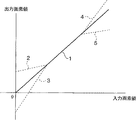
画像処理回路112では、はじめに階調変換回路が原画像Org(x,y)を階調変換曲線f()を用いてf(Org(x、y))に変換する(s201)。ここで、x、yは原画像上の座標である。階調変換曲線f()としては例えば図10の様な曲線形を用いる。例えば、実線1は傾き1の関数である。つまり、入力値と出力値を変更しない(入力値と出力値とが等しい)場合であり、ダイナミックレンジ圧縮の効果はない。次に、破線2の場合は低画素値側のダイナミックレンジを圧縮する関数形であり、破線3は低画素値側のダイナミックレンジを拡大する関数形である。同様に破線4は高画素値側のダイナミックレンジを拡大するものであり、破線5は高画素値側のダイナミックレンジを圧縮する関数形である。
なお、実施する場合には、これらの曲線形は微分連続(微分可能かつ連続な関数)に構成する方が好ましい。微分不連続点(カーブが微分可能又は連続でない点に対応する階調変換後の画像の上の点)で擬輪郭が生じることがあるからである。
次に、DWT変換回路(離散ウェーブレット変換回路)114は階調変換後の画像f(Org(x、y))に対して2次元の離散ウェーブレット変換処理を行い、画像成分(変換係数)を計算して出力するものである。メインメモリ109に記憶された画像データは、DWT変換回路114により順次読み出されて変換処理が行われ、再びメインメモリ109に書きこまれる。本実施の形態におけるDWT変換回路114において、入力された画像信号は遅延素子およびダウンサンプラの組み合わせにより、偶数アドレスおよび奇数アドレスの信号に分離され、2つのフィルタpおよびuによりフィルタ処理が施される。図11Aのsおよびdは、各々1次元の画像信号に対して1レベルの分解を行った際のローパス係数およびハイパス係数を表しており、次式により計算されるものとする。
d(n)=x(2×n+1)−floor((x(2×n)+x(2×n+2))/2)・・・・(11)
s(n)=x(2×n)+floor((d(n−1)+d(n))/4)・・・(12)
ただし、x(n)は変換対象となる画像信号である。
以上の処理により、画像信号に対する1次元の離散ウェーブレット変換処理が行われる。2次元の離散ウェーブレット変換は、1次元の変換を画像の水平・垂直方向に対して順次行うものであり、その詳細は公知であるのでここでは説明を省略する。図11Bは2次元の変換処理により得られる2レベルの変換係数群の構成例であり、画像信号は異なる周波数帯域の画像成分HH1、HL1、LH1、...、LLに分解される(s202)。図11Bにおいて、HH1、HL1、LH1、...、LLの各々(以下サブバンドと呼ぶ)が周波数帯域毎の画像成分を示す。
そして、成分変換回路では(13)式に従いサブバンド毎の画像成分hn(x、y)を変換する。ここで、変換後の画像成分をh2n(x、y)とし、nはサブバンドのカテゴリを示す。
h2n(x、y)=(1/f’(Org(x,y)))×hn(x、y)・・・・・・(13)
この処理により、原画像Org(x,y)の画像成分に対し階調変換処理によりf’()倍(f’()はhn(x、y)に対応するOrg(x,y)における階調変換曲線f()の傾き)となった階調変換処理後の画像の画像成分を、原画像Org(x,y)の画像成分とほぼ同一の値に変換することができる。ここで、もっとも最下層の低周波成分であるLLサブバンドの画像成分は変更しない。これにより、画像全体のダイナミックレンジは変更されるが、高周波成分に対応する画像成分は原画像の画像成分とほぼ同一の値を保つことができる。尚、(13)式の右辺に所定の定数を乗算するようにしてもよく、この場合はダイナミックレンジを変更しつつ、画像の高周波成分の調節(強調または抑制)を行うことができる。(13)式によると、原画像の画素値範囲が圧縮された領域については高周波成分が強調され、原画像の画素値範囲が拡大された領域については高周波成分が抑制される。しかし、例えば上述のように(13)式の右辺に任意の定数を乗算するための調整手段を更に備えてもよい。
ところで、階調変換処理によってダイナミックレンジを変更した画像にはオーバーシュート等のアーティファクトは生じない。しかし、(13)式の処理では高周波成分を変更することで高周波成分の増幅はできるが、同時にオーバーシュート等のアーティファクトが生じる場合がある。
これを防ぐため、(13)式に代えて、(14)式のように高周波成分を変更することが有効である。
h2n(x、y)=hn(x、y)+(1/f’(x、y)−1)×fn(hn(x、y))・・・(14)
ここで、関数fn()は図12又は図13のような曲線形を有する。また、これらの曲線は微分連続(微分可能かつ連続な関数)となっており、擬輪郭等が生じないようになっている。また、エッジ部分で生じる画像成分は通常の成分(エッジ部分以外の成分)に比べ、値が大きくなっており、これらの曲線形はエッジ成分に対応する画像成分を抑制する、または0(ゼロ)にする曲線形となっている。これにより(14)式では画像成分が所定閾値より大きい場合にはfn(hn(x、y))は抑制された値または0となり、h2n(x、y)は抑制された値またはほぼhn(x、y)となる。一方、画像成分が通常の大きさである場合にはh2n(x,y)は(13)式と同様の値となるものである。
これにより、ダイナミックレンジは変更され、高周波成分のうち有効な画像成分(所定値以下の画像成分)は階調変換前の画像の画像成分の大きさと同一となる。また、高周波成分のうちオーバーシュート等が生じる原因となる画像成分(所定値を超える画像成分)は変更されない、あるいは抑えて変更されるので、オーバーシュート等を抑制することができる。また、関数形fn()の傾きを、入力値が所定値以下の範囲で1以上に(1より大きく)することで、高周波成分の強調を、オーバーシュートを抑制しながら行うことができる。よって、ダイナミックレンジの変更と高周波成分の変更とを、オーバーシュート等を抑制しながら行うことができる。
そして、逆DWT変換回路116は成分変換回路115で変換された画像成分(変換係数)に対し逆離散ウェーブレット変換を以下のように行う(s204)。メインメモリ109に記憶された変換された画像成分は逆離散ウェーブレット変換回路116により順次読み出されて変換処理が行われ、再びメインメモリ109に書きこまれる。本実施の形態における逆DWT変換回路116による逆離散ウェーブレット変換処理の構成は図11Cに示すものとする。入力された画像成分はuおよびpの2つのフィルタ処理を施され、アップサンプリングされた後に重ね合わされて画像信号x’が出力される。これらの処理は次式により行われる。
x’(2×n)=s’(n)−floor((d’(n−1)+d’(n))/4)・・・・・・(15)
x’(2×n+1)=d’(n)+floor((x’(2×n)+x’(2×n+2))/2)・・・・(16)
以上の処理により、変換係数に対する1次元の逆離散ウェーブレット変換処理が行われる。2次元の逆離散ウェーブレット変換は、1次元の逆変換を画像の水平・垂直方向に対して順次行うものであり、その詳細は公知であるのでここでは説明を省略する。
以上のように実施の形態1では、画像のダイナミックレンジが変更され、かつオーバーシュート等のアーティファクトを抑制しながら高周波成分の調節された良好な出力画像を得ることができる。さらには、ダイナミックレンジ変更処理と、周波数帯毎の画像成分の変更による周波数帯毎の強調または抑制処理とを有機的に行うように構成することもできる。
(実施の形態2)
実施の形態2について図14の処理の流れに従い説明する。実施の形態1と同様な処理については説明を省略する。
まず、DWT変換回路114で原画像Org(x,y)をDWT変換処理する。ここで得られた画像成分をhorgn(x、y)とする(s701)。次に、階調変換回路113で、原画像Org(x、y)を階調変換曲線f()で階調変換処理する(s702)。そして、階調変換処理された画像f(Org(x、y))をDWT変換回路114でDWT変換処理し、得られた画像成分をhn(x、y)とする(s703)。ここで、実施の形態1と同様にnはサブバンドのカテゴリをしめし、x、yは座標を示す。
次に、成分変換回路115は画像成分hn(x、y)に、式(17)に示すように画像成分horgn(x、y)を変換して加算し、新たな画像成分h2n(x、y)を得る(s704)。
h2n(x、y)=hn(x、y)+(1−f’(Org(x、y)))×horgn(x、y)・・・(17)
ここで、もっとも最下層の低周波成分であるLLサブバンドの画像成分は変更しない。これにより、ダイナミックレンジを変更した後の画像の高周波成分の大きさと原画像の高周波成分の大きさとをほぼ同一に保てるものである。この場合、高周波成分の足しこみを原画像の高周波成分を用いて行うため、より精度よく処理後の高周波成分の大きさを原画像の高周波成分の大きさに近づけることができる。尚、(17)式の右辺第2項に所定の定数を乗算するようにしてもよく、この場合はダイナミックレンジを変更しつつ、画像の高周波成分の調節(強調または抑制)を行うことができる。
また、(17)式に代えて(18)式のようにしても同様の効果が得られる。
h2n(x、y)=horgn(x、y)・・・・・・(18)
ところで、階調変換処理によってダイナミックレンジを変更した画像にはオーバーシュート等のアーティファクトは生じない。しかし、(17)式の処理では、原画像の高周波成分を変換して加算することで高周波成分の増幅はできるが、同時にオーバーシュート等のアーティファクトを生じさせる原因となる原画像の成分をも加算することになり、オーバーシュートが生じる場合がある。
これを防ぐため、(17)式に代えて(19)式のように高周波成分を変更することが有効である。
h2n(x、y)=hn(x、y)+(1−f’(Org(x、y)))×fn(horgn(x、y))
・・・・(19)
ここで、fn()は図12又は図13のような曲線形を有する。エッジ部分で生じる画像成分は通常の成分に比べ、値が大きくなっており、これらの曲線形はエッジ成分に対応する画像成分を抑制された値または0にする曲線形となっている。これにより(19)式では画像成分が大きい場合にはfn(horgn(x、y))は抑制された値または0となり、h2n(x、y)は抑制された値またはほぼhn(x、y)となる。一方、画像成分が通常の大きさである場合にはh2n(x,y)は(17)式と同様の値となるものである。
これにより、ダイナミックレンジは変更され、高周波成分のうち有効な画像成分(所定値以下の画像成分)は階調変換前の画像の画像成分の大きさとほぼ同一となる。また、高周波成分のうちオーバーシュート等が生じる原因となる画像成分(所定値を超える画像成分)は変更されない、あるいは抑えて変更されるので、オーバーシュート等を抑制することができる。また、関数形fn()の傾きを、入力値が所定値以下の範囲で1以上に(1より大きく)することで、高周波成分の強調を、オーバーシュートを抑制しながら行うことができる。よって、ダイナミックレンジの変更と高周波成分の変更とを、オーバーシュート等を抑制しながら行うことができる。
そして、成分変更回路115で変更した画像成分に基づき、逆DWT変換回路116では逆DWT変換処理を行う(S705)。
実施の形態2では、画像のダイナミックレンジが変更され、かつオーバーシュート等のアーティファクトを抑制しながら高周波成分の調節された良好な出力画像を得ることができる。さらには、ダイナミックレンジ変更処理と、周波数帯毎の画像成分の変更による周波数帯毎の強調または抑制処理とを有機的に行うように構成することもできる。また、加える高周波成分として原画像の高周波成分を用いるため、処理後画像の高周波成分をさらに精度よく原画像の高周波成分に近づけることができる。
(実施の形態3)
実施の形態3について図15の処理の流れに従い説明する。実施の形態1と同様な処理については説明を省略する。
まず、階調変換回路113で、原画像Org(x、y)を階調変換曲線f()で階調変換処理し処理後画像f(Org(x、y))を得る(s801)。次にDWT変換回路114で原画像をDWT変換処理し、ここで得られた画像成分をhn(x、y)とする(s802)。ここで、実施の形態1と同様にnはサブバンドのカテゴリをしめし、x、yは座標を示す。
次に、成分変換回路115は画像成分hn(x、y)を式(20)に示すように変換し、新たな画像成分h2n(x、y)を得る(s803)。
h2n(x、y)=(1−f’(Org(x、y)))×hn(x、y)・・・・・・(20)
尚、ここで最下限の低周波成分LLの値は全て0(ゼロ)とする。
これにより、h2n(x、y)を逆DWT変換すると、階調変換曲線の傾きに依存した高周波成分だけの画像Hr(x、y)を得ることができる。尚、(20)式の右辺に任意の定数を乗算するようにしてもよく、この場合は、画像の高周波成分の調節(強調または抑制)を行うことができる。
次に、逆DWT変換回路116は成分変換回路115で変換した成分に基づき、逆DWT変換を行い復元画像を得る(s804)。そして、階調変換回路113で得られた画像f(Org(x,y))と逆DWT回路116で得られた画像Hr(x,y)を(21)式に示すように加算して処理画像Prc(x,y)を得る(s805)。尚、この加算は図8の画像合成回路117によって行われる。
Prc(x、y)=f(Org(x,y))+Hr(x,y)・・・(21)
ところで、階調変換処理によってダイナミックレンジを変更した画像にはオーバーシュート等のアーティファクトは生じない。しかし、(20)式で得られた高周波成分はオーバーシュート等のアーティファクトが生じる原因となる原画像の成分を含有している可能性がある。したがって、この画像成分をそのまま逆変換した画像にはオーバーシュートの原因となる成分が含まれ、これを加算するとオーバーシュートが生じる場合がある。
これを防ぐため、(20)式に代えて(22)式のように高周波成分を変更することが有効である。
h2n(x、y)=(1−f’(Org(x、y)))×fn(hn(x、y))・・・・・・(22)
ここで、fn()は図12又は図13のような曲線形を有する。エッジ部分で生じる画像成分は通常の成分に比べ、値が大きくなっており、これらの曲線形はエッジ成分に対応する画像成分を抑制された値または0にする曲線形となっている。これにより、(22)式では画像成分が大きい場合にはfn(hn(x、y))が抑制された値または0となる結果、h2n(x、y)も抑制された値または0となる。一方、画像成分が通常の大きさである場合には、(22)式のh2n(x,y)は(20)式と同様の値となるものである。
階調変換後の画像に(20)式の画像成分を逆DWT変換した画像を加えることにより、ダイナミックレンジが変更され、かつ高周波成分は原画像の大きさとほぼ同一の画像を得ることができる。
さらに、(22)式のように画像成分の大きさに応じて画像成分を変更することで、高周波成分のうち有効な画像成分(所定値以下の画像成分)を階調変換前の画像の画像成分の大きさとほぼ同一とすることができる。また、高周波成分のうちオーバーシュート等が生じる原因となる画像成分(所定値を超える画像成分)は変更されない、または抑えて変更されるので、オーバーシュート等を抑制することができる。また、関数形fn()の傾きを、入力値が所定値以下の範囲で1以上に(1より大きく)することで高周波成分の強調を、オーバーシュートを抑制しながら行うことができる。よって、ダイナミックレンジの変更と高周波成分の変更とを、オーバーシュート等を抑制しながら行うことができる。
実施の形態3では、画像のダイナミックレンジが変更され、かつオーバーシュート等のアーティファクトを抑制しながら高周波成分の調節された良好な出力画像を得ることができる。さらには、ダイナミックレンジ変更処理と、周波数帯毎の画像成分の変更による周波数帯毎の強調または抑制処理とを有機的に行うように構成することもできる。また、加える高周波成分として原画像の高周波成分を用いるため、処理後画像の高周波成分をさらに精度よく原画像の高周波成分に近づけることができる。また、DWT変換処理を1回しか行わないため、計算時間を短縮することができる。
(実施の形態4)
実施の形態4はエッジ構造を保存した状態でダイナミックレンジを変更する第4の形態の画像処理に関するものである。実施の形態1と同様な処理については説明を省略する。図16は実施の形態4の画像処理回路112の構成を示す図であり、901は原画像から平滑化画像を減じることで高周波成分を作成する高周波成分作成回路であり、902は原画像を階調変換することでダイナミックレンジを変更する階調変換回路であり、903は高周波成分作成回路901で作成された高周波成分を変換し、階調変換回路902で用いた階調変換曲線の傾きに応じて階調変換後画像に加算する高周波成分加算回路である。
図17は実施の形態4の処理の流れを説明する図であり、図17の処理の流れに従い画像処理回路112の処理を説明する。
CPUバス107を介して前処理回路106で処理された原画像f(x、y)をCPU108の制御により受信した画像処理回路112における高周波成分作成回路601は、(23)式から(27)式に従い平滑化画像を作成する(s1001)。ここで、fus(x、y)を平滑化画像、f(x、y)を原画像、d1、d2、d3、d4をマスクサイズとする。

d2=y−d・・・・・・(25)
d3=x+d・・・・・・(26)
d4=x−d・・・・・・(27)
このような移動平均による平滑化画像作成方法を用いると計算時間が短いという効果がある。
尚、平滑化画像fus(x、y)を(28)〜(32)式で示すようなモルフォロジ演算を用いて計算してもよい。
f2(x、y)=min{f(x+x1、y+y1)−D(x1、y1)|x1×x1+y1×y1≦r1×r1}・・・・・・(28)
f3(x、y)=max{f2(x+x1、y+y1)+D(x1、y1)|x1×x1+y1×y1≦r1×r1}・・・・・・(29)
f4(x、y)=max{f3(x+x1、y+y1)+D(x1、y1)|x1×x1+y1×y1≦r1×r1}・・・・・・(30)
fus(x、y)=min{f4(x+x1、y+y1)−D(x1、y1)|x1×x1+y1×y1≦r1×r1}・・・・・・(31)
ここで、D(x、y)は次式で示される円盤状フィルタで、r1は入力画像に応じて選択される任意の定数である。
D(x、y)=0、x×x+y×y≦r1×r1のとき
=−∞、その他のとき ・・・・・・(32)
ここで得られたfus(x、y)は、そのプロファイルがエッジ構造を保存しているものであり、従来の鮮鋭化処理の欠点であるオーバーシュート、アンダーシュートを起こしにくいものである。
また、同様にfus(x、y)をメディアンフィルタを用いて作成してもよい。この場合の平滑化画像も、エッジ構造を比較的保存するため、モルフォロジ演算を用いたときと同様、従来の鮮鋭化処理の欠点であるオーバーシュート、アンダーシュートを起こしにくいものである。
次に、高周波成分作成回路901は(33)式に従い高周波成分fh(x、y)を作成する(s1002)。
fh(x、y)=f(x、y)−fus(x、y)・・・・・・(33)
そして、階調変換回路602は階調変換曲線F1()を用いて(34)式で示すように原画像を階調変換することにより原画像のダイナミックレンジを変更し、階調変換後の出力画像f0(x、y)を得る(s1003)。
f0(x、y)=F1(f(x、y))・・・・・・(34)
(34)式における階調変換では所定の目的にそったダイナミックレンジが得られ、また、オーバーシュート等のアーティファクトは何ら生じない。しかし、単なる階調変換にすぎないため、ダイナミックレンジ(画素値範囲)が圧縮された領域では微細構造を構成する高周波成分も圧縮されるため、微細構造の観察がしにくくなる。
次に高周波成分加算回路903では高周波成分fh(x、y)を(35)式に従って変換した後の高周波成分fh2(x、y)を作成する。
fh2(x、y)=F(fh(x、y))・・・・・・(35)
ここで、変換曲線F()は例えば図18に示すような関数である。この関数の曲線形状によれば、図18に示される所定絶対値(閾値)301以上の高周波成分を0(ゼロ)として、所定絶対値301未満の高周波成分の大きさを不変(曲線の傾きが1)とすることができる。尚、所定絶対値以上の高周波成分を徐々に0まで減少させるような曲線形状や、所定絶対値未満の高周波成分の大きさを線形又は非線形に増大または減少させる曲線形状を採用することもできる。
次に、高周波成分加算回路903は、階調変換曲線の微係数(傾き)に従って(36)、(37)式に示すように高周波成分fh2(x、y)を変換し、階調変換後の画像f0(x、y)に加算することにより、処理後画像fdr(x、y)を得る(s1004)。
fdr(x、y)=f0(x、y)+F3(f(x、y))xc(f(x、y))×fh2(x、y)・・・・・・(36)
![]()
以上により、この処理では、微細構造などの有効情報に対応する高周波成分は復元されるとともに、エッジ部分の高周波成分は0として階調変換後の画像に加算されないため、エッジ形状が保存され、オーバーシュート等に生じない。
一般にオーバーシュートを示す高周波成分の絶対値は所定値(閾値)より大きく、微細構造に対応する高周波成分の絶対値は所定値より小さいという性質がある。また、この絶対値の大きい高周波成分は画像のエッジ部分に生じる。さらに、高周波成分を復元した処理後画像においてオーバーシュートとして感じるのはこの所定値以上の高周波成分の値が特異的に突出している場合である。
そのため、加算される高周波成分の絶対値が所定値よりも大きい場合に0とすることにより、オーバーシュートを抑制し、エッジ構造を保存することができる。
(36)式に従いダイナミックレンジ(画素値範囲)が変更された程度に応じて高周波成分が復元されるため、ダイナミックレンジが変更された後においても微細構造が良く見えるという効果がある。さらに、実施の形態1と同様の効果により、オーバーシュートの原因となる高周波成分を0としているため、処理後の画像のエッジ構造は保持されるものである。
以上のように実施の形態4によれば、階調変換によりダイナミックレンジを変更するとともに、オーバーシュートの元になる高周波成分をカットして高周波成分を復元するため,エッジ構造が保持されるとともに、微細構造が階調変換前の構造に復元された処理後画像を得ることができる。また、さらに微細構造に対応する高周波成分を所定の関数で変換することにより、階調変換前の微細構造に対し所定の強調又は抑制を行うこともできる。よって、ダイナミックレンジまたは所定画素値範囲の変更された良好な処理後画像を得ることができる。
さらに、平滑化画像をモルフォロジ演算で作成すると、本来オーバーシュートが生じにくいものであるが、さらに上述の変換曲線を用いることで、オーバーシュートに対応する高周波成分を抑制することができ、さらに効果的にオーバーシュートを抑制することができる。
同様に、平滑化画像をメディアンフィルタで作成した場合も、本来オーバーシュートが生じにくいものであるが、さらに上述の変換曲線を用いることで、オーバーシュートに対応する高周波成分を抑制することができ、さらに効果的にオーバーシュートを抑制することができる。
(実施の形態5)
実施の形態5はエッジ構造を保存した状態でダイナミックレンジを変更する第5の形態の画像処理に関するものであり、実施の形態1と同様の処理に関しては説明を省略する。実施の形態4の画像処理回路112の構成も図16を用いて説明する。902は原画像を階調変換することでダイナミックレンジを変更する階調変換回路であり、901は階調変換回路902で階調変換された画像からその平滑化画像を減じることで高周波成分を作成する高周波成分作成回路であり、903は高周波成分作成回路901で作成された高周波成分を、階調変換回路902で用いた階調変換曲線の傾きに応じて変換し階調変換後の画像に加算する高周波成分加算回路である。
図19は実施の形態5の処理の流れを説明する図であり、図19の処理の流れに従い画像処理回路112の処理を説明する。
CPUバス107を介して前処理回路106で処理された原画像f(x、y)をCPU108の制御により受信した画像処理回路112における階調変換回路902は階調変換曲線F1()を用いて(38)式で示すように原画像を階調変換することにより原画像のダイナミックレンジを変更し、階調変換後の出力画像f0(x、y)を得る(s1201)。
f0(x、y)=F1(f(x、y))・・・・・・(38)
次に高周波成分作成回路901は、階調変換後画像の平滑化画像を作成する(s1202)。ここで、fus(x、y)を平滑化画像とする。実施の形態4で示したように平滑化画像の作成には移動平均、モルフォロジ演算、メディアンフィルタ等のいずれの方法を用いてもよい。
次に、高周波成分作成回路901では(39)式に従い高周波成分fh(x、y)を作成する(s1203)。
fh(x、y)=f0(x、y)−fus(x、y)・・・・・・(39)
次に高周波成分加算回路903では高周波成分fh(x、y)を(40)式に従い変換した後の高周波成分fh2(x、y)を作成する。
fh2(x、y)=F(fh(x、y))・・・・・・(40)
ここで、変換曲線F()は例えば図18に示すような関数形をしている。
次に、高周波成分加算回路903は階調変換曲線の微係数(傾き)に従い(41)(42)式に示すように高周波成分fh2(x、y)を変換し階調変換後の画像f0(x、y)に加算し処理後画像fdr(x、y)を得る(s1204)。
fdr(x、y)=f0(x、y)+F3(f(x、y))×c(f(x、y))×fh2(x、y)・・・・・・(41)
![]()
(41)、(42)式に従いダイナミックレンジが変更された量に応じて高周波成分を復元するため、ダイナミックレンジが変更された後においても微細構造を実質的に保存することができる。さらに、実施の形態1と同様の効果により、オーバーシュートの原因となる高周波成分の足しこみ量を0としているため、処理後の画像のエッジ構造は保持されるものである。
以上の実施の形態5によれば、階調変換によりダイナミックレンジを変更し、オーバーシュートの原因となる高周波成分をカットして高周波成分を復元するため,処理後の画像においてエッジ構造を保持したまま、微細構造を実質的に保持でき、または微細構造を強調もしくは抑制することができる。
さらに、平滑化画像をモルフォロジ演算で作成した場合には本来オーバーシュートが生じにくいものであるが、さらに上述の変換曲線を用いることでオーバーシュートに対応する高周波成分を抑制することができ、さらに効果的にオーバーシュートを抑制することができる。
同様に、平滑化画像をメディアンフィルタで作成した場合にも本来オーバーシュートが生じにくいものであるが、さらに上述の変換曲線を用いることでオーバーシュートに対応する高周波成分を抑制することができ、さらに効果的にオーバーシュートを抑制することができる。
(実施の形態6)
実施の形態6は階調変換後の画像を複数の周波数帯の周波数係数に分解し、その周波数係数を変換することでエッジ構造を保存したまま,ダイナミックレンジ変更及び周波数処理の効果を得るものである。図20は実施の形態6の構成を示す図であり、実施の形態1と同様の処理については説明を省略する。図20において112は画像処理回路を示し、1301はダイナミックレンジを変更するための階調変換を行う階調変換回路を示し,1302は階調変換回路1301で階調変換された画像を例えばウェーブレット変換、ラプラシアンピラミッド変換等で複数の周波数帯に分解し周波数係数を得る周波数帯分解回路、1303は階調変換回路1301の階調変換曲線の傾き及び、原画像またはその平滑化画像の画素値に依存して周波数係数の値を変換する係数変換回路であり、1304は係数変換回路1303で変換された係数に基き、逆ウェーブレット変換、逆ラプラシアンピラミッド変換等で周波数係数を逆変換することで画像を再構成する逆変換回路である。
図21は階調変換回路1301でダイナミックレンジを変換するための階調変換曲線の一例を示す。ここで横軸は入力画像の画素値、縦軸は出力画像の画素値を示す。図22はこの発明の実施の形態6による画像処理回路112の処理の流れを示すフローチャートである。図23は周波数係数を変換する曲線形の一例を示す。横軸が入力係数であり、縦軸が出力係数である。
図22の処理の流れに従い、実施の形態6について以下に説明する。階調変換回路1301は図21に示す階調変換曲線F()に従い原画像f(x、y)の階調変換を行う(s1501)。この場合、例えば、曲線2では低画素値領域のレンジを圧縮し、逆に曲線3では同レンジを拡大することになる。同様に曲線4は高画素値領域のレンジを拡大し、曲線5は同レンジを圧縮することになる。曲線F()は偽輪郭などの発生を防ぐため微分連続(微分可能かつ連続な関数)であることが望ましい。また、S1501の処理は単なる階調変換であるため、階調変換後の画像においてオーバーシュート等は生じない。
周波数係数分解回路1302は階調変換回路1301で階調変換することによりダイナミックレンジが変更された画像F(f(x、y))に対して2次元の離散ウェーブレット変換処理を行い、周波数係数を出力するものである(s1502)。この周波数分解の方法は例えば実施の形態1で説明したウェーブレット変換を用いればよく、その場合、周波数帯ごとの周波数係数HH1、HL1、LH1、...、LLに分解される。尚、周波数分解は次に示すようなラプラシアンピラミッド変換の方法を用いてもよい。
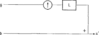
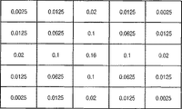
図24Aのgおよびbは各々1レベルの分解を行った際の画像の低解像度近似画像および高周波成分係数を表しており、低解像度近似画像gは画像信号xをローパスフィルタによりフィルタ処理し、ダウンサンプリングして得られる。また、高周波成分係数bは画像信号xと、低解像度近似画像gをアップサンプリングしさらにローパスフィルタによりフィルタ処理した画像との差分をとることにより得られる。ローパスフィルタは例えば図24Bに示すようなフィルタを用いる。ラプラシアンピラミッド変換の方法はこの処理を低解像度近似画像gに対して繰り返し行うことで各周波数帯の周波数係数を得るものであり、その詳細は公知であるのでここでは説明を省略する。
また、図24Cがラプラシアンピラミッドの逆変換である。入力された高周波成分係数bと低解像度近似画像gをアップサンプリングしローパスフィルタによりフィルタ処理をしたものとを重ね合わせることにより画像信号x’が出力される。ローパスフィルタは例えば図24Bに示すようなフィルタを用いる。ラプラシアンピラミッド変換の方法はこの処理を各レベルに対して繰り返し行うことで合成画像を得るものであり、その詳細は公知であるのでここでは説明を省略する。
次に係数変換回路1303は例えば図23に示すよう変換曲線F2()に従い周波数係数を変換する(s1503)。この場合、所定絶対値(閾値)以下の領域1601の係数のみを変換し、所定絶対値を超える係数を不変に保つ。ここで、hn(x、y)はnレベルの周波数係数で所定絶対値以下の領域1601の係数とし、h2n(x、y)は(43)式に従ってhn(x、y)を係数変換した後の係数の値とする。
h2n(x、y)=f4(f(x、y))×(1/F’(x、y))×hn(x、y)・・・・・・(43)
ここでf4()を原画像f(x、y)又はその平滑化画像に依存した曲線形として、例えば所定画素値以下のとき値を小さくし、所定画素値を超えるとき値を大きくするような曲線形とする。所定絶対値(閾値)を超える周波数係数は不変に保つ。この所定絶対値は画像のエッジに対する係数の大きさにより実験的に決められる値であり、所定絶対値を超える係数を不変に保つことでエッジ構造は保存され、再構成画像においてオーバーシュート等のアーティファクト抑制することができる。尚、図23の変換曲線F2()は以上のことを模式的に表現したものであり、領域1601の係数は必ずしもリニアに変換されるのではなく、(43)式に基づいて変換される。
また、所定絶対値(閾値)以下の周波数係数(微細構造などの有効成分に対応)の大きさを階調変換曲線に基づき変換するので、処理後の画像においても、原画像と同様の微細構造のコントラストを維持することができる。さらに、所定絶対値以下の周波数係数を原画像f(x、y)等の値に基き増減させることで、原画像の画素値の大きいところの有効情報(微細構造)を再構成画像上で鮮鋭化すること等が可能となる。また低画素値領域の係数を増加させないことでノイズの強調を抑えることもできる。
尚、以上のことから(43)式は次の(43)’式のように表現することもできる。
h2n(x、y)=f4(f(x、y))×(1/F’(x、y))×hn(x、y)、
hn(x、y)が所定絶対値(閾値)以下のとき
=hn(x、y)、hn(x、y)が所定絶対値(閾値)を超えるとき
・・・・・(43)’
次に逆変換回路1304で、係数変換された画像成分を逆変換することで再構成画像を作成する(s1504)。
以上実施の形態6によればダイナミックレンジを変更するとともに、オーバーシュート等を抑制しながら、ダイナミックレンジ変更前の微細構造の情報を実質的に保持することができる。さらに、原画像やその平滑化画像の画素値に依存して周波数係数を増減することにより、再構成画像においてノイズ抑制や鮮鋭化の効果も得られる。
(実施の形態7)
実施に形態7はエッジ構造を保存したまま,ダイナミックレンジ変更及び周波数処理の効果を得るものである。図25は実施の形態7の構成を示す図であり、実施の形態1と同様の処理については説明を省略する。図25において112は画像処理回路を示し、1801は原画像をウェーブレット変換またはラプラシアンピラミッド変換の方法等で複数の周波数帯に分解し第一の周波数係数を得る第一の周波数帯分解回路、1802はダイナミックレンジを変更するための階調変換を行う階調変換回路を示し、1803は階調変換回路1802で階調変換された画像をウェーブレット変換またはラプラシアンピラミッド変換の方法等で複数の周波数帯に分解し第二の周波数係数を得る第二の周波数帯分解回路、1804は階調変換回路1802の階調変換曲線の傾き及び、原画像またはその平滑化画像の画素値に依存して第一の周波数係数の値を変換する係数変換回路であり、1805は係数変換回路1804で変換された係数を第二の周波数係数に加算する係数加算回路、1806は係数加算回路1805で得られた周波数係数を逆ウェーブレット変換または逆ラプラシアンピラミッド変換の方法等で逆変換することにより画像を再構成する逆変換回路である。
図26はこの発明の実施の形態7による画像処理回路112の処理の流れを示すフローチャートである。図27は係数変換回路1804において用いられる係数変換曲線の一例を示し、横軸が入力係数、縦軸が出力係数を示す。
図26の処理の流れに従い、実施の形態7について以下に説明する。まず、第一の周波数帯分解回路1801で原画像を周波数帯分解処理し、ここで得られた画像成分をhorgn(x、y)とする(s1901)。周波数係数に分解する方法としてはウェーブレット変換、ラプラシアンピラミッド変換の方法等いずれの方法を用いてもよいが、ここでは二次元の離散ウェーブレット変換(DWT)を用いた方法について説明する。
次に、階調変換回路1802で、原画像Org(x、y)を階調変換曲線f()で階調変換する(s1902)。そして、階調変換処理された画像f(Org(x、y))を第二の周波数帯分解回路1803でDWT変換処理し得られた周波数係数をhn(x、y)とする(s1903)。ここで、他の実施の形態と同様にnはサブバンドのカテゴリを示し、x、yは座標を示す。
次に、係数変換回路1804及び係数加算回路1805により、周波数係数hn(x、y)に、(44)式に示すように周波数係数horgn(x、y)を変換して加算し、新たな周波数係数h2n(x、y)を得る(s1904)。
h2n(x、y)=hn(x、y)+(1−f’(Org(x、y)))×horgn(x、y)・・・・・・(44)
ここで、horgn(x、y)は図27で示す変換曲線であらかじめ変換されているものであり、所定絶対値(閾値)を超える(エッジ部分に対応する)係数はあらかじめ0とされている。したがって(44)式においては微細構造に対応する有効成分のみが階調変換曲線の傾きに応じて変換されて階調変換後画像の周波数係数に加算されることになり、復元後の画像において原画像の有効な高周波成分の大きさを実質的に保存することができる。この場合、高周波成分の加算を原画像の高周波成分を用いて行うため、処理後画像の高周波成分の大きさをより精度よく原画像の高周波成分の大きさに近づけることができる。
また、(44)式にかえ(45)式の様にしても同様の効果が得られる。すなわち、エッジ構造が保存されずオーバーシュート等が生じることのないよう、この場合も、horgn(x、y)が図27の変換曲線であらかじめ変換され、当該変換されたhorgn(x、y)が0でないときのみh2n(x、y)を(当該変換された)horgn(x、y)とし、当該変換されたhorgn(x、y)が0であるときはh2n(x、y)をhn(x、y)とする。
h2n(x、y)=horgn(x、y)、変換されたhorgn(x、y)が0でないとき
=hn(x、y)、変換されたhorgn(x、y)が0であるとき
・・・(45)
係数加算回路1805で得た周波数係数に基づき、逆変換回路1806では逆変換処理を行う(s1905)。
以上の実施の形態7によれば原画像の微細構造に対応する有効な係数のみが階調変換曲線の傾きに応じて変換されて階調変換後の画像の周波数係数に加算されることになり、復元後の画像においては原画像の有効な高周波成分の大きさを実質的に保存することができる。この場合、高周波成分の加算を、原画像の高周波成分を用いて行うため、処理後画像の高周波成分の大きさをより精度よく原画像の高周波成分の大きさに近づけることができる。また、ダイナミックレンジを変更するとともに周波数処理を行った画像においても、エッジ構造が保存されるため、オーバーシュート等を抑制することができる。
(実施の形態8)
実施に形態8はエッジ構造を保存したまま,ダイナミックレンジ変更及び周波数処理の効果を得る画像処理に関するものである。図28は実施の形態8の構成を示す図であり、実施の形態1と同様の処理については説明を省略する。図において112は画像処理回路を示し、2101は原画像をウェーブレット変換またはラプラシアンピラミッド変換の方法等で複数の周波数帯に分解し周波数係数を得る周波数帯分解回路、2102は後に行うダイナミックレンジを変更するための階調変換曲線の傾きに基づき係数を変換する係数変換回路、2103は係数変換回路2102で変換して得た係数を逆変換する逆変換回路、2104は逆変換回路2103で逆変換して得た画像のダイナミックレンジを変更するための階調変換回路である。
図29はこの発明の実施の形態8による画像処理回路112の処理の流れを示すフローチャートである。図30は係数変換回路2102において用いられる係数変換曲線の一例を示し、横軸が入力係数、縦軸が出力係数を示す。
図29の処理の流れに従い、実施の形態8について以下に説明する。周波数帯分解回路2101は原画像f(x、y)に対して2次元の離散ウェーブレット変換処理を行い、周波数係数を出力するものである(s2201)。この周波数分解の方法は例えばウェーブレット変換またはラプラシアンピラミッド変換の方法等任意の方法を用いることができるが、ここでは2次元の離散ウェーブレット変換を用いて周波数帯ごとの周波数係数HH1、HL1、LH1、...、LLに分解するものとする。
次に係数変換回路2102は階調変換回路2104で用いる階調変換曲線(例えば図21に示すような変換曲線)F()に従い周波数係数を変換する(s2202)。この場合、図30に示すように所定絶対値(閾値)以下の領域2301の係数のみを変換し、所定絶対値を超える係数を不変に保つ。所定絶対値は画像のエッジ部分に対する係数の大きさにより実験的に決められる値であり、所定絶対値を超える係数を不変に保つことでエッジ構造が保存され、再構成画像においてオーバーシュート等のアーティファクトが生じるのを抑制することができる。
ここで、hn(x、y)はnレベルの周波数係数とし、h2n(x、y)は(46)式に従って、hn(x、y)が所定絶対値(閾値)以下の領域2301に属する係数であるか否かに基づいてhn(x、y)を係数変換した後の係数の値とする。
h2n(x、y)=f5(f(x、y))×(1/F’(x、y))×hn(x、y)、
hn(x、y)が所定閾値以下のとき
=hn(x、y)、hn(x、y)が所定閾値を超えるとき
・・・・・・(46)
ここで関数f5()は例えば原画像f(x、y)又はその平滑化画像の画素値に依存した曲線形を有し、例えば所定画素値以下のとき値を小さくし、所定画素値を超えるとき値を大きくするような曲線形とする。
次に、逆変換回路2103でh2n(x、y)逆変換(逆DWT変換)する(S2203)。そして復元画像f2(x、y)を得る。そして、階調変換回路2104で復元画像f2(x、y)を(47)式に示すように階調変換して、ダイナミックレンジが変更された画像f3(x、y)を得る(s2204)。
f3(x、y)=F(f2(x、y))・・・・・・(47)
以上の実施の形態8によれば、あらかじめダイナミックレンジを変更するための階調変換の曲線形に基づいて周波数係数を変更しているため、ダイナミックレンジ変更後の画像における高周波成分の大きさと原画像の高周波成分の大きさをほぼ同一に保つことができる。また、所定絶対値範囲の係数の値を変更しないため、エッジ構造が保存され、周波数処理及びダイナミックレンジ変更処理の施された画像においてもオーバーシュート等が生じるのを抑制することができる。また、原画像を多重周波数係数に分解しているため、ノイズ抑制、鮮鋭化処理、その他の処理との複合処理も容易に行うことができる。例えば、ノイズ抑制などでは原画像の係数に基づく解析処理などが行われるからである。
以上説明した各実施の形態によれば、画像のエッジ構造の崩壊またはオーバーシュートの発生を抑制または回避しつつ、画像のダイナミックレンジまたは部分的画素値範囲の変更された良好な画像を得ることができる。
(実施の形態9)
以下、添付図面を参照し、本発明の一側面としての画像処理装置4100を説明する。なお、各図において同一の参照符号は同一部材を示し、重複説明は省略する。本発明の画像処理装置4100は、例えば、X線撮影を行うときに用いられるX線撮影装置、又は当該X線撮影装置の一部(例えば、X線撮影装置の画像処理部)として実現される。
図31を参照するに、画像処理装置4100は、CPU4110と、メモリ4120と、操作パネル4130と、表示部4140と、前処理部4150と、データ収集部4160と、画像処理部4170とを有する。画像処理装置4100はCPUバス4105を有し、各要素がCPUバス4105を介し互いにデータまたは情報を授受可能に構成されている。ここで、図31は、本実施例の画像処理装置4100を示すブロック図である。なお、本実施例に示すように、画像処理装置4100はデータ収集部4160に接続された撮像部4190を有し、当該撮像部4190によって撮影されたX線画像の画像処理を一装置において可能な構成としている。しかし、本実施例の画像処理装置4100は他の撮像装置に任意に接続可能に構成されても良く、また、単に後述する画像処理(鮮鋭化等の周波数処理)を達成可能な構成のみであってもよい。
かかる構成において、画像処理装置4100は撮像部4190から得られる画像(生画像)を前処理部4150によって前処理(例えば、オフセット補正、ゲイン補正、Log補正)を施すことで原画像を作成する。原画像とは、生画像に対して前処理が施された画像、例えば撮像部190の特性に依存した補正の行われた、体裁が整えられた画像を意味する。しかしながら、原画像は医師が診断を行うには不十分であるため、更に画像処理部4170によって鮮鋭化処理等を施すことにより最も診断に適した、又は所望の画像を得ることができる。なお、この最適な画像又は所望の画像をQA画像(画質保証画像)と表現する場合もある。
CPU4110はMPUなど名称の如何を問わずいかなるプロセッサであってもよく、CPUバス4105に接続されている。CPU4110はCPUバス4105を介し各部の動作を制御する。また、CPU4110はメモリ4120に格納されたプログラムを用いて、オペレータの操作パネル4110の操作に従った画像処理装置4100全体の動作制御等を行う。
メモリ4120は、例えば、画像処理装置4100の動作プログラムや処理に必要な各種のデータなどを格納するROMなどの不揮発性メモリと、画像及び必要な制御プログラムを一時的に格納するRAMなどの揮発性メモリとを含む。
操作パネル4130は、例えば、キーボード、スイッチ、タッチパネル等より構成され、オペレータの画像処理装置4100の操作を可能とする。また、表示部4140は、例えば、CRT、液晶ディスプレイ等のような表示装置及び/又は印刷装置を含み、QA画像を出力可能に構成されている。
前処理部4150は生画像に対する前処理を実行可能に構成された回路であって、CPUバス4105及びデータ収集部4160に接続されている。なお、本実施例における前処理は、撮像部4190の後述する2次元X線センサ4194の各画素(図示しない)の特性(暗電流、検出感度等)の差によって生じる画像の誤差を補正する処理を含む。より特定的には、前処理とはオフセット補正、ゲイン補正、対数変換(Log変換)等を指し、かかる技術は当業界で周知のいかなる技術も適用可能である。前処理部部4150はデータ収集部4160より授受された生画像(又は、メモリ4120を介しデータ収集部4160より授受された生画像)をメモリ4120に格納されたデータを基に、CPU4110の制御に基づき補正を行う。なお、前処理部4150は画像処理を実行する回路の一部であり、後述する画像処理部4170の一部として構成されてもよい。前処理部4150はかかる処理を施した画像(原画像)を画像処理部4170及び/又はメモリ4120に出力する。
データ収集部4160は撮像部4190、前処理部4150及びCPUバス4105に接続され、撮像部4190より出力された生画像を所定の電気信号に変換し前処理部4150及び/又はメモリ4120に供給する。データ収集部4160は、例えば、14ビットA/D変換器を有し、撮像部4190の出力に比例したデジタル信号を前処理部4150及び/又はメモリ4120に供給する。これにより前処理部4150は上述した前処理、例えば、デジタル信号を対数変換し、X線の線量の対数に比例したデジタル信号に変換することができる。
画像処理部4170は、低周波成分作成部4171と、高周波成分作成部4172と、成分変換部4174と、高周波成分加算部4176とを有し、CPUバス4105を介し各々データを授受可能に構成されている。低周波成分作成部4171は原画像から平滑化画像(即ち、低周波成分又は低周波画像のことであり、本明細書ではいずれも原則同義として使用する)を作成する。高周波成分作成部4172は原画像から平滑化画像を減じることで高周波成分(高周波画像)を作成する。成分変換部4174は高周波成分作成部4172によって作成された高周波成分を所定の関数に従って変換する。なお、かかる所定の関数については、後述する動作において詳細に説明するものとし、ここでの説明を省略する。高周波成分加算部4176は、成分変換部4174によって変換された高周波成分を原画像又は平滑化画像に加算する。本実施例の画像処理部4170は所定の閾値以上の絶対値を有する高周波成分を原画像に足し込まない。または、画像処理部4170は所定の倍率で変換された平滑化画像に対し、所定の閾値以上の絶対値を有する高周波成分を同一の倍率(当該所定の倍率)で変換し、所定の閾値未満の絶対値を有する高周波成分を任意に変換して得た高周波成分を足し込む。これにより、エッジ構造が保存されてオーバーシュート等が抑制されると共に、鮮鋭化等の所望の周波数処理を行うことができる。
なお、図36に示すように、画像処理部4170は画像処理部4170aに置換されてもよい。ここで、図36は、本発明の別の実施例の画像処理装置4100aを示すブロック図である。画像処理部4170aは周波数係数分解部4178と、係数変換部4180と、逆変換部4182とを有し、CPUバス4105を介し各々データを授受可能に構成されている。
周波数係数分解部4178は原画像に対して離散ウェーブレット変換(DWT変換と称する場合もある)又はラプラシアンピラミッド変換の方法による周波数分解処理を施す回路を備える。かかる回路は、例えば、図37A,Bに示すような回路であるが、当業界周知のいかなる技術の適用も制限するものではない。ここで、図37Aは離散ウェーブレット変換処理を施す例示的な回路構成を示した図であり、図37Bはラプラシアンピラミッド変換の方法による周波数分解処理を施す例示的な回路構成を示した図である。かかる構成において、周波数係数分解部4178は各周波数帯毎の周波数係数(ウェーブレット変換係数又はラプラシアンピラミッド変換係数)を得る。
係数変換部4180は周波数係数分解部4178で得られた各周波数帯毎の周波数係数を変換する係数変換回路であり、所定の関数に基づき周波数係数を変換する。なお、かかる所定の関数については、後述する動作において詳細に説明するものとし、ここでの説明を省略する。
逆変換部4182は係数変換部4180で変換された周波数係数に基づき逆離散ウェーブレット変換(逆DWT変換と称する場合もある)又はラプラシアンピラミッド方法における逆変換(逆ラプラシアンピラミッド変換)を行う回路を備える。かかる回路は、例えば、図38A,Bに示すような回路であるが、当業界周知のいかなる技術の適用も制限するものではない。ここで、図38Aは逆離散ウェーブレット変換処理を施す例示的な回路構成を示した図であり、図38Bはラプラシアンピラミッド方法による逆変換処理(逆ラプラシアンピラミッド変換処理)を施す例示的な回路構成を示した図である。かかる構成において、逆変換部4182は変換された周波数係数を逆変換することでQA画像を得ることができる。
なお、画像処理部4170と画像処理部4170aは画像の処理方法において異なるが、各処理方法は後述する動作の説明において容易に理解されるであろう。
撮像部4190は、X線発生部4192と2次元X線センサ4194とを有し、データ収集部4160に接続される。図31に示されるように、撮像部4190は、被検査体Pを介しX線発生部4192と2次元X線センサ4194が対向する位置に配置される。かかる構成において、撮像部4190は、吸収及び散乱等、被検査体Pとの相互作用を経たX線を撮像し、そのX線画像(生画像)をデータ収集部4160に供給する。X線発生部4192はオペレータによって操作可能であって(オペレータが操作パネル4130を操作して、メモリ4120に格納された動作プログラムによってCPU4110が制御することの意味も含む)、例えばX線管球を含む回路より構成される。一方、2次元センサ4194は、例えば、X線の入射側から順に配置された蛍光体とアモルファス・シリコン光センサとから構成される積層構造を有し、データ収集部4160に接続されている。なお、撮像部4190は、上述の構成に限定されず、当業界周知の技術を適用可能であることは言うまでもない。また、撮像部4190は、画像処理装置4100から独立した構成要素であってもよく、本発明の画像処理装置4100は、必ずしも撮像部4190を必要としない。例えば、撮像部4190が独立の装置として画像処理装置100に接続されても良い。
以下、上述の画像処理装置4100の動作を説明する。なお、以下の説明において、画像処理装置4100は、例えば、医療用X線撮影装置として具体化されている。
先ず、操作パネル4130を操作することによってオペレータから撮影の指示がなされると、X線発生部4192は被検査体Pに対してX線ビームを放射する。X線発生部4192から放射されたX線ビームは、被検査体Pを減衰しながら透過して、2次元X線センサ4194に到達する。かかるX線ビームは2次元X線センサ4194により検出されX線画像として出力される。ここでは、2次元X線センサ4194から出力されるX線画像を、例えば、人体部画像等とする。
データ収集部4160は、2次元X線センサ4194から出力されたX線画像をデジタル信号に変換して前処理部4150に供給する。前処理部4150は、データ収集部4160から出力されたデジタル信号に対して、オフセット補正処理やゲイン補正処理等の前処理を行う。この前処理部4150で前処理が行われた信号は、原画像として、CPU4110の制御により、CPUバス4105を介しメモリ4120及び/又は画像処理部4170に転送される。
次に、図32及び図33を参照しながら、画像処理部4170の動作、即ち、本発明の好適な実施例の画像処理方法について説明する。ここで、図32は、本発明の一実施例としての画像処理方法を示すフローチャートである。図33は、成分変換部4174で高周波成分を変換するために用いる変換曲線であり、横軸が入力高周波成分、縦軸が変換後の高周波成分を示す。ここで、図33は入力成分が+の場合の変換曲線を示すものであるが、係数が−の場合にも同様に変換することができる。つまり奇関数の第一象限だけを示した図であることを理解されたい。
画像処理部4170の低周波成分作成部4171は前処理部4150より出力された画像(原画像)をCPUバス4150を介し授受する。まず、低周波成分作成部4171は原画像から以下に示す(48)式に従い平滑化画像を作成する(ステップ5000)。ここで、原画像をf(x、y)、平滑化画像をfus(x、y)、d1、d2、d3及びd4をマスクサイズとする。
なお、ステップ5000によって作成される平滑化画像fus(x、y)は(48)式に示す関数で得られるもののみに限定されない。例えば、以下に示す(49)式乃至(52)式によって表されるモルフォロジカルフィルタ演算を用いて作成してもよい。
また、同様にfus(x、y)をメディアンフィルタ演算を用いて作成してもよい。この場合には平滑化画像のエッジ構造が比較的保存されるため、モルフォロジカルフィルタ演算を用いたときと同様に従来の鮮鋭化処理の欠点であるオーバーシュートを起こしにくいものである。
次に、高周波成分作成部4172は(55)に従い高周波成分fh(x、y)を作成する。
![]()
次に、成分変換部4174は(56)式に従い高周波成分fh(x、y)を変換曲線(関数F1())で変換し、高周波成分fh1(x、y)を作成する(ステップ5010)。
![]()
一般にオーバーシュートを示す高周波成分の絶対値は一定値より大きく、微細構造に対応する高周波成分の絶対値は小さい性質がある。また、この絶対値の大きい高周波成分は画像のエッジ部分に生じる。さらに、QA画像において、オーバーシュートとして感じるのは、エッジ部において一部の画素の画素値がその近傍の画素の画素値に対して特異的に過度に飛び出ている場合である。そのため、高周波成分の絶対値が一定値(閾値)よりも大きい場合、該高周波成分の値を0とする(その結果、該高周波成分は原画像に足し込まれない)ことで、オーバーシュートが抑制され、エッジ構造が保存されるものである。
次に、高周波成分加算部4176はこの変換された高周波成分fh1(x、y)を(57)式に示すように原画像に加算する(ステップ5015)。ここでfprc(x、y)を処理後の画像とする。
![]()
![]()
また、所定閾値未満の高周波成分を種々の線形又は非線形の変換関数で変換することにより、種々の目的に合った周波数処理を行うことができる。例えば、強調したい微細構造の高周波成分の絶対値の分布に応じ、所定絶対値範囲の高周波成分を特に強調する処理、比較的不要な高周波成分の絶対値の分布に応じ、所定絶対値範囲の高周波成分を弱く強調する、強調しない若しくは抑制する処理、又はそれらを複合した強調・抑制処理等を行うことができる。
かかる処理を実行した後の画像fprc(x、y)は画像処理部4170からメモリ4120及び表示部4140に供給される。オペレータ、例えば撮影技師、や医師は、表示部4140に出力される画像によって、撮影された画像の確認や診断を行うことができる。
以上説明したようにかかる画像処理方法は、所定閾値以上の絶対値を有する高周波成分は0とすることで原画像に加算されないので、エッジ形は保存され、またオーバーシュートが生じない。また、所定閾値未満の高周波成分だけをそのまま又は所定の関数で変換した後に原画像に加算することにより、微細構造などの有効情報に対応する高周波成分を強調する鮮鋭化、所定範囲の絶対値を有する有効な又は所望の高周波成分だけを強調する鮮鋭化等、種々の目的に合った周波数処理を行うことができる。例えば、人体に埋め込まれた金属片や骨部等のエッジ部に不自然な影響を与えず自然な強調画像を得ることができる。
なお、平滑化画像を上述のモルフォロジ演算で作成した場合には本来オーバーシュートが生じにくいものであるが、さらに上述のような変換曲線を用いた処理を行うことでオーバーシュートに対応する高周波成分を抑制することができ、さらに効率よくオーバーシュートを抑制できるものである。
同様に、平滑化画像をメディアンフィルタで作成した場合にも本来オーバーシュートが生じにくいものであるが、さらに上述のような変換曲線を用いた処理を行うことでオーバーシュートに対応する高周波成分を抑制することができ、さらに効率よくオーバーシュートを抑制できるものである。
以下、図34及び図35を参照しながら、上記画像処理方法の変形例としての画像処理方法、即ち画像処理部4170で行われる動作の変形例を説明する。ここで、図34は、本発明の別の画像処理方法を示すフローチャートである。図35は、成分変換部4174で高周波成分を変換するために用いる変換曲線であり、横軸が入力高周波成分、縦軸が変換後の高周波成分を示す。なお、図35は入力成分が+の場合の変換曲線を示すものであるが、係数が−の場合にも同様に変換することができる。つまり奇関数の第1象限だけを示した図である。また、画像処理装置4100の全体の動作は上述した通りであって、ここでの重複説明は省略する。
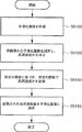
上述した方法と同様、画像処理部4170の低周波成分作成部4171は前処理部4150より出力された画像(原画像)をCPUバス4105を介し授受する。低周波成分作成部4171は原画像から上述した(48)式に従い平滑化画像を作成する(ステップ5100)。ここで、原画像をf(x、y)、平滑化画像をfus(x、y)とする。なお、平滑化画像fus(x、y)の作成には上述の方法と同様、モルフォロジカルフィルタリング等どのような手法を用いてもよい。
次に、高周波成分作成部4172は(55)式に従い高周波成分fh(x、y)を作成する。即ち、ステップ5100で得られた平滑化画像fus(x、y)と原画像f(x、y)との差分を計算し、高周波成分からなる差分画像を抽出する(5105)。
次に、成分変換部4174は(59)式に従い高周波成分fh(x、y)を変換曲線(関数F2())で変換し、高周波成分fh2(x、y)を作成する(ステップ5110)。
![]()
次に、この変換された高周波成分fh2(x、y)を平滑化画像fus(x、y)に加算する(ステップ5115)。ここでfprc(x、y)を処理後の画像とする。
![]()
よって、例えば、エッジ構造を構成する(すなわち、所定閾値以上の絶対値を有する)高周波成分及び全低周波成分を一定比率で変更しつつ、それ以外の高周波成分を不変とすれば、エッジ構造が保存されつつダイナミックレンジが変更されると共に、有効な微細構造が不変に維持された処理後画像を得ることができる。
また、所定閾値未満の高周波成分を種々の線形又は非線形の変換関数で変換することにより、種々の目的に合った周波数処理を行うことができる。例えば、強調したい微細構造の高周波成分の絶対値の分布に応じ、所定絶対値範囲の高周波成分を特に強調する処理、比較的不要な高周波成分の絶対値の分布に応じ、所定絶対値範囲の高周波成分を弱く強調する、強調しない若しくは抑制する処理、又はそれらを複合した強調・抑制処理等を行うことができる。
かかる処理を実行した後の画像fprc(x、y)は画像処理部4170からメモリ4120及び表示部4140に供給される。オペレータ、例えば撮影技師、又は医師は表示部4140に出力される画像によって、撮影された画像の確認又は診断を行うことができる。
上述の画像処理方法では関数F1()で変換された高周波成分を原画像に加算するものであるが、かかる変形例では関数F2()で変換された高周波成分を平滑化画像に加算するものである。かかる変形例であっても、上述の画像処理方法と同様の作用を奏するものである。その結果、微細構造などの有効情報に対応する高周波成分の強調による鮮鋭化、又はノイズなどの不要情報に対応する高周波成分の抑制によるノイズ削減等の効果を奏すると共に、エッジ部分の高周波成分の大きさを低周波成分の大きさに対し相対的に不変とすることでエッジ形が保存されオーバーシュートが生じないという効果がある。
(実施の形態10)
以下、図36乃至図42Cを参照しながら、画像処理装置4100の画像処理部4170を画像処理部4170aに置換した場合の画像処理方法、即ち、画像処理部4170aで行われる動作の変形例を説明する。ここで、図39は、画像処理部4170aによる処理を示すフローチャートである。図40は、2次元の離散ウェーブレット変換処理により得られる2レベルの変換係数群の構成例を示す。図41は、係数変換関数F3()の変換曲線の形状を示すグラフであり、図中の点線より右側は傾き1の直線となっている。図42Aは原画像のプロファイル、図42Bはエッジ構造を保存しない鮮鋭化処理後の画像のプロファイル、図42Cはエッジ構造を保存した場合の鮮鋭化処理後の画像のプロファイルを示す。
まず、画像処理部4170aの周波数係数分解部4178は原画像f((x、y))に対して2次元の離散ウェーブレット変換処理(DWT変換処理)を行い、周波数係数を計算して出力する。より詳細には、周波数係数分解部4178はメモリ4120に記憶された原画像データ(例えば、図42Aに示す)を順次読み出し変換処理を行う。DWT変換された周波数係数は再びメモリ4120に書きこまれる。より詳細には、入力された画像信号は遅延素子およびダウンサンプラの組み合わせにより、偶数アドレスおよび奇数アドレスの信号に分離され、2つのフィルタpおよびuによりフィルタ処理が施される。図37Aに示すように、sおよびdは各々1次元の画像信号に対して1レベルの分解を行った際のローパス係数およびハイパス係数を表しており、(61)式及び(62)式により計算されるものとする。
以上の処理により、画像信号に対する1次元のDWT変換処理が行われる。2次元のDWT変換処理は、1次元の変換を画像の水平・垂直方向に対して順次行うものであり、その詳細は公知であるのでここでは説明を省略する。図40に示すように、画像信号は異なる周波数帯域の周波数係数HH1、HL1、LH1、...、LLに分解される(ステップ1200)。図40において、HH1、HL1、LH1、...、LL等(以下サブバンドと呼ぶ)が周波数帯毎のウェーブレット変換係数(周波数係数)を示す。
次に、係数変換部4180は、例えば、図41に示すような変換曲線F3()に従い周波数係数を変換する(ステップ5205)。図41は、横軸が入力係数であり、縦軸が出力係数を示す。なお、図41は入力係数が+の場合の変換曲線を示すものであるが、入力係数が−の場合にも同様に変換することができる。つまり奇関数の第一象限だけを示した図であることを理解されたい。
この曲線形(関数F3())によれば一定絶対値(閾値)以上の高周波係数を変換せず(例えば、傾き1)、一定閾値未満(a3で示す範囲)の周波数係数(高周波係数)の大きさを増加させるものである。なお、かかる関数形は、後述するように所定の閾値以上の周波数係数と所定の閾値未満の周波数係数を異なる倍率で変換するに足りるものであり、本発明が図41に示した関数形にのみ限定されることを意味するものではない。このような曲線を用いてLLサブバンド係数以外の全ての周波数係数を変換するものである。そして、メモリ4120に変換後の周波数係数を保存しておく。ここで所定閾値は予め実験的に求められている値である。あるいは、例えば、この所定閾値はサブバンド係数の絶対値の累積ヒストグラムを作成し累積頻度が80%となる係数の絶対値を所定閾値の値としてもよい。また、所定閾値は周波数分解が進んだ係数(より低周波に対応する係数)ほど大きくするほうが好ましい。より低周波に対応する係数において、エッジ成分に対応する周波数係数は大きくなるからである。尚、空間周波数の高い上位(例えばレベル1)のサブバンドの所定閾値は0でよい場合もある。
また、一定閾値未満の係数を変換する場合に、原画像の画素値又はLL成分の値に依存して係数を変更する割合を変えてもよい。例えば原画像における低画素値領域に対応する係数は増加率を減じる等する。このことにより、低画素値領域で目立ちやすいノイズが強調されてしまうことを回避できる。
このような係数空間において、微細構造などの有効情報に対応する周波数係数はその絶対値が小さく、エッジ部分に対応する周波数係数はその絶対値が大きいという特性がある。従って、図41のような曲線形(関数F3())で係数を変換すると微細構造などの有効構造に対応する周波数係数は増加し、エッジ構造に対応する周波数係数は不変に保つことになる。
図43乃至図50は同じく、所定の閾値以上の周波数係数と所定の閾値未満の周波数係数を異なる倍率で変換する例を示している。ここで、図43乃至図50は、周波数係数を変換する曲線(関数)の例を示すグラフであり、図中の点線は所定の閾値を通り縦軸に平行な線分であり、該点線を境界として変換特性(傾き等)が異なることを示している。図43は、所定絶対値(閾値)未満(図中a3a)の係数を増加させているものであり、係数0を生じさせないものである。この場合には図41に示す場合と比較して、絶対値の小さな係数ほど強調されると共に、係数のダイナミックレンジは圧縮されるという特徴がある。図44は、所定絶対値(閾値)未満(a3b)の係数を減少させると共に、係数を0から単調増加させているものである。この場合には鮮鋭化の効果はなくノイズ抑制などの効果がある。
図45は、所定絶対値(閾値)未満(a3c)の係数のみならず、所定絶対値以上の係数を増加しているが、a3c以外の範囲の係数の増加の割合を範囲a3cよりも小さくした例である。つまり、範囲a3c以外の変換曲線の傾き1より大きい場合である。この場合、エッジ構造を完全には保存できないものの、エッジ部でのオーバーシュートを抑制しつつ、微細構造等の有効成分を強調することができる。また、エッジ構造の壊れが問題にならない程に範囲a3c以外の傾きを1より大きく又は小さくすることは、範囲a3c以外の傾きを1に保つことと実質的に均等である。
図46は、所定絶対値(閾値)未満(a3d)以外、すなわち所定絶対値以上の範囲の傾きは1としたのだが、全体の曲線形を微分連続(微分可能かつ連続な関数、又は少なくとも傾きが連続)としたものである。これにより係数の変化率が連続となり、処理後の画像に偽輪郭等のアーティファクトを生じさせないために好ましい場合があり得る。尚、DWT変換処理によって得られる高周波サブバンドの場合、上述の高周波画像と異なり係数空間での表現であるため、変換関数が微分不連続(微分不可能又は不連続)であるからといって直ちに処理後の画像に偽輪郭等のアーティファクトが発生するわけではない。
図47及び図48は、所定絶対値(閾値)未満で所定の範囲(図47中a3e、及び図48中a3f)の係数のみを増減したものである。尚、図47及び図48の第2の閾値未満の曲線の傾きは1でなくてもよい。このような曲線形では範囲a3e及びa3fとそれらより係数が小さい範囲とで異なる係数の増減を行えると共に、エッジ構造も保存できるものである。これにより、ノイズ等の不要成分を抑制しながら所望の有効成分だけを強調することが可能である。
図49及び図50はエッジ構造に対応する係数(図中、a3g及びa3h)が増減する(傾きが1でない)曲線形になっている。この場合、エッジ構造に対応する全サブバンドの係数(空間周波数の最も低い成分であるLLサブバンドに関しては全係数)を同じ比率で変更するとよい。そうすれば、エッジ部分に関してはその画素値が単純に増減されるだけであり、オーバーシュートやエッジのボケは生じずエッジ構造が保存される。例えば、全サブバンドの係数を2倍した場合の復元画像は原画像のダイナミックレンジを単純に2倍した画像になり、オーバーシュートやエッジのボケは生じない。これと同様の理屈により、エッジ構造を構成する全サブバンドの係数(LLに関しては全係数)を一定比率で変更しつつ、それ以外の係数を任意に変更すれば、エッジ構造が保存されつつダイナミックレンジが変更されると共に、微細構造が変更(強調又は抑制)された処理後画像を得ることができる。尚、エッジ構造を構成する(すなわち、所定閾値以上の絶対値を有する)全サブバンドの係数(LLに関しては全係数)を一定比率で変更しつつ、それ以外の係数を不変とすれば、エッジ構造が保存されつつダイナミックレンジが変更されると共に、有効な微細構造が不変に維持された処理後画像を得ることができる。上述の図43乃至図50に示す関数形は、上記実施例(高周波画像を平滑化画像に加算する実施例)にも適用可能である。但し、上述したように、高周波画像を用いた場合には変換関数に不連続点や微分不連続点(微分不可能な点)があると偽輪郭等のアーティファクトが出やすいため、微分連続の(微分可能かつ連続な)変換関数を用いた方がよい。その場合、不連続点や折れ点を滑らかな曲線に変更すればよい。
そして、逆変換部4182は係数変換部4180で変換された周波数係数に対し逆離散ウェーブレット変換(逆DWT変換)を行う(ステップ5210)。より詳細には、関数F3()で変換されたメモリ4120に記憶された周波数係数は逆変換部4182により順次読み出され、逆変換処理が行われる。逆変換部4182で逆DWT変換された画像信号は再びメモリ4120に書きこまれる。図38Aに示すように、入力された画像成分(s’及びd’)はu及びpの2つのフィルタ処理を施される。そして、フィルタ処理された出力はアップサンプリングされた後に重ね合わされて画像信号x’が出力される。これらの処理は(63)式及び(64)式に従って行われる。
かかる処理を実行した後の画像は画像処理部4170aからメモリ4120及び表示部4140に供給される。オペレータ、例えば撮影技師、又は医師は表示部4140に出力される画像によって、撮影された画像の確認又は診断を行うことができる。
図42Bは、係数変換部4180において、LLサブバンドを除くすべてのサブバンドの係数全体を2倍に変換したものである。一方、図42Cは、図41において、範囲a3の係数を2倍とし、それ以外の係数は不変(即ち、関数F3()の傾きが1)に保った場合の結果画像である。係数全体を変換した場合には例えば図42Bの矢印で示すようにオーバーシュートが強く現れている。しかし、所定絶対値以上の係数を不変に保った図42Cでは微細構造は強調されているが、エッジ構造は保存されオーバーシュートが生じていないのがわかる。
図41において、変換関数F3()は微分不可能かつ不連続な点を有するが、逆変換後の画像では偽輪郭などのアーティファクトは生じないものである。所定の絶対値を有する係数(変換曲線の微分不可能かつ不連続な点に対応する係数)は係数空間上でランダムに散乱しているため、逆変換した画像上では、ラインなど連続的な境界線として視覚的に認識される構造が現れないためである。ウェーブレット係数はあくまで周波数係数であり、逆ウェーブレット変換処理により、周波数係数の大きさに応じて、所定の画像空間が復元されるものであるからである。尚、係数空間上で画像のエッジ部に対応して所定絶対値の周波数係数が連続的に並ぶ場合もあるが、この場合、変換関数F3()のような不連続関数により係数変換された後に現れる係数空間上での連続的な構造は、復元画像上でもエッジ部に沿って連続的な構造として現れるため、偽輪郭としては認識されない。
上述は離散ウェーブレット変換を用いて説明したが、画像を多重周波数成分に分解する方法ならなんでもよく、例えばラプラシアンピラミッド変換の方法を用いてもよい。図37Bに示す周波数係数分解部4178において、g及びbは各々1レベルの分解を行った際の画像の低解像度近似画像および高周波成分係数を表している。低解像度近似画像gは画像信号xをローパスフィルタによりフィルタ処理し、ダウンサンプリングして得られる。また高周波成分係数bは画像信号xと、低解像度近似画像gをアップサンプリングしさらにローパスフィルタによりフィルタ処理した画像との差分をとることにより得られる。ローパスフィルタは例えば図51に示すようなフィルタを用いる。図51は図37Bに示す周波数係数分解部4178に適用可能なフィルタ形を示した図である。ラプラシアンピラミッド変換の方法はこの処理を低解像度近似画像gに対して繰り返し行うことで各周波数帯の周波数係数を得るものであり、その詳細は公知であるのでここでは説明を省略する。
また、図38Bに示すように、入力された高周波成分係数bと、低解像度近似画像gをアップサンプリングしローバスフィルタによりフィルタ処理をしたものとを重ね合わせることにより画像信号x’が出力される。ローパスフィルタは例えば図51に示すようなフィルタを用いる。ラプラシアンピラミッドの方法(逆ラプラシアンピラミッド変換)はこの処理を各レベルに対して繰り返し行うことで合成画像を得るものであり、その詳細は公知であるのでここでは説明を省略する。
以上の様に、かかる実施形態の画像処理方法は画像を複数の周波数帯の周波数係数に分解し、その周波数係数を変換することでエッジ構造を保存したまま,鮮鋭化等の周波数処理の効果を得るものである。かかる方法は、エッジ構造を保ったまま、周波数帯毎との強調又は抑制の程度をきめ細かく調整できる効果がある。また、エッジ構造を保持したまま周波数処理をしても、処理後画像上に偽輪郭などのアーティファクトが生じない効果もある。また、分解レベルが低周波になるに従い所定絶対値(閾値)を大きくすることで、より効果的にエッジ構造を保存した周波数処理を行うことができる。
以上説明したように、実施の形態9以下の各実施の形態によれば、対象画像に含まれるエッジ部のエッジ構造の崩壊を抑制または回避しつつ、所望の空間周波数成分が強調又は抑制された良好な画像を得ることのできる画像処理装置及び方法、並びに、コンピュータ可読媒体及びプログラムを提供することができる。
実施の形態9による画像処理装置及び方法は、所定の閾値以上の絶対値を有する高周波成分と所定の閾値未満の絶対値を有する高周波成分とを異なる倍率で変換可能である。よって、所定の閾値以上の絶対値を有する高周波成分を強調しないようにすることができる。また、所定の閾値以上の絶対値を有する高周波成分を、平滑化画像に対する変換倍率と同様の倍率で変換することができる。この結果、オーバーシュートが抑制され、又はエッジ構造が保存される。よって、かかる画像処理装置及び方法から得られる処理後の画像は、例えばエッジ部分に不自然さをなくすことができる。また、所定の閾値未満の絶対値を有する高周波成分は任意に変換し得るので、高周波成分を適切に強調(鮮鋭化)又は抑制することができる。
また、実施の形態10による画像処理装置及び方法は、所定の閾値以上の絶対値を有する高周波数係数(高周波数帯の係数)と所定の閾値未満の絶対値を有する高周波数係数とを異なる倍率で変換することができる。この結果、所定の閾値以上の絶対値を有する高周波数係数を、例えば、不変に保ったり、又は低周波係数(低周波数帯の係数)に対する変換倍率と同様の倍率で変換できる。よって、オーバーシュートが抑制され、又はエッジ構造が保存される。更に、かかる画像処理装置及び方法は周波数帯毎の強調又は抑制度をきめ細かく調整できる。また、高周波帯毎に係数値に基づく変換を行う方法を採用したことにより、オーバーシュートを抑制し、又はエッジ構造を保存する周波数処理を実行しても、処理後画像上に他の偽輪郭(例えば、エッジ部に沿って視認され得る帯状のボケ)などが生じないという優れた効果もある。また、所定の閾値未満の絶対値を有する高周波数係数を増加又は減少することで、微細構造の強調(鮮鋭化)又はノイズの低減を図ることができる。更に、かかる画像処理装置及び方法は、前記所定の閾値未満であって、更に小さい第2の閾値未満の絶対値を有する高周波数係数を強く減少させ、又は0にする変換を行ってもよい。この構成は画像中のノイズ成分を抑制しながら画像中の有効成分を適切に変換(強調又は抑制等)することができる。また、高周波数帯の帯域毎に閾値を異ならせる(例えば、高周波数帯の帯域が低周波になるに従い閾値を大きくする)ことにより、より効果的にオーバーシュートを抑制し、又はエッジ構造を保存することができる。
(他の実施の形態)
前述した実施形態の機能の実現又は処理ステップの実行のために各種のデバイスを動作させるべく、該各種デバイスと接続された装置あるいはシステム内のコンピュータに、前記実施形態の機能の実現又は処理ステップの実行のためのソフトウエアのプログラムコードを供給し、その装置あるいはシステム内のコンピュータ(CPUあるいはMPU等)が、格納されたプログラムに従って前記各種デバイスを動作させることによって前記実施形態の機能の実現又は処理ステップの実行をすることも本発明の範疇に含まれる。
またこの場合、前記ソフトウエアのプログラムコード自体が前述した実施形態の機能の実現又は処理ステップの実行をすることになり、そのプログラムコード自体、及びそのプログラムコードをコンピュータに供給するための手段、例えばかかるプログラムコードを格納した記憶媒体は本発明を構成する。
かかるプログラムコードを格納する記憶媒体としては例えばフロッピーディスク、ハードディスク、光ディスク、光磁気ディスク、CD−ROM、磁気テープ、不揮発性のメモリカード、ROM等を用いることが出来る。
また、コンピュータが供給されたプログラムコードを実行することにより、前述の実施形態の機能の実現又は処理ステップの実行がなされるだけではなく、そのプログラムコードがコンピュータにおいて稼働しているOS(オペレーティングシステム)、あるいは他のアプリケーションソフトウェア等と協働して前述の実施形態の機能の実現又は処理ステップの実行がなされる場合にも、かかるプログラムコードが本発明を構成することは言うまでもない。
更に、供給されたプログラムコードが、コンピュータの機能拡張ボードやコンピュータに接続された機能拡張ユニットに備わるメモリに格納された後、そのプログラムコードの指示に基づいてその機能拡張ボードや機能拡張ユニットに備わるCPU等が実際の処理の一部または全部を行い、その処理によって前述した実施形態の機能の実現又は処理ステップの実行がなされる場合にも、かかるプログラムコードが本発明を構成することは言うまでもない。
尚、上述のプログラムは上述のコンピュータ可読記憶媒体に格納される態様で取引対象となるだけでなく、インターネットその他の通信ネットワークを利用してオンライン配信される態様で独立の取引対象となり得ることは言うまでもない。
以上、実施の形態を詳細に説明したが、本発明はその要旨の範囲内で種々の変形及び変更が可能である。Technical field
The present invention relates to an image processing apparatus and method, and more particularly to an image processing apparatus and method for changing the dynamic range of image data, and image processing for performing frequency enhancement or suppression processing such as sharpening on an image including an edge structure or the like. The present invention relates to an apparatus and a method.
Background art
For example, an X-ray chest image is composed of a lung field image region where X-rays are easily transmitted and a mediastinal image region where X-rays are very difficult to transmit. wide. For this reason, it has been considered difficult to obtain an X-ray chest image capable of simultaneously observing both the lung field and the mediastinum.
Therefore, as a method of avoiding this problem, SPI Vol. 626 Medicine XIV / PACSIV (1986). In this method, the pixel value of the processed image is SD, the pixel value (input pixel value) of the original image (input image) is Sorg, the pixel value of the low-frequency image of the original image is SUS, and constants A, B, C (For example, A = 3, B = 0.7), and is expressed by equation (1).
SD = A [Sorg−SUS] + B [SUS] + C (1)
In this method, the weighting of the high frequency component (first term) and the low frequency component (second term) can be changed. For example, when A = 3 and B = 0.7, the high frequency component is emphasized and the entire dynamic range is obtained. The effect of compressing is obtained. This method has been evaluated by five radiologists as being effective for diagnosis compared to unprocessed images.
Increasing the ratio of A in equation (1) increases the ratio of the high frequency component and provides a sharpening effect, and changing the ratio of B changes the size of the low frequency component and changes the dynamic range of the image SD. It is what is done.
Japanese Patent No. 2509503 discloses that the processed pixel value is SD, the original pixel value (input pixel value) is Sorg, the average profile of a plurality of Y direction profiles of the original image is Py, and the plurality of X direction profiles. A method expressed by the equation (2) is described in which the average profile of Px is Px.
SD = Sorg + F [G (Px, Py)] (2)
Here, the characteristics of the function F (x) will be described. First, when “x> Dth”, F (x) becomes “0”, and when “0 ≦ x ≦ Dth”, F (x) defines the intercept “E”. ”, Which decreases monotonously with the inclination being“ E / Dth ”, and is expressed by equation (3).
When F (x) = E− (E / Dth) x, 0 ≦ x ≦ Dth
= 0, x> Dth (3)
Py = (■ Pyi) / n (4)
Px = (■ Pxi) / n (5)
However, (i = 1 to n), Pyi, and Pxi are profiles. For example, G (Px, Py) is
G (Px, Py) = max (Px, Py) (6)
It is shown by. In this method, among the pixel value (density value) range of the original image, the pixel value (density value) range in which the pixel value of the low-frequency image is equal to or less than Dth is compressed.
Moreover, as a method similar to the method of Japanese Patent No. 2509503, it was described in "Journal of Japanese Society of Radiological Technology, Vol. 45, No. 8, Aug. 10, 1989, Anan et al." And Japanese Patent No. 2663189. There is a way. In this method, the monotonically decreasing function f (X) is defined with SD as the pixel value after processing, Sorg as the original pixel value, and SUS as the average pixel value when the moving average is taken with the mask size of M × M pixels in the original image. And expressed by the equations (7) and (8).
SD = Sorg + f (SUS) (7)
SUS = ■ Sorg / M 2 (8)
This method differs from the method (2) in the method of creating a low frequency image. In the method (2), a low-frequency image is created using one-dimensional data, whereas in this method, a low-frequency image is created using two-dimensional data. This method also compresses the pixel value (density value) range in which the pixel value of the low-frequency image is not more than Dth among the pixel value (density value) range of the original image.
The dynamic range compression method described above has a function f1 () for converting a low-frequency image and is expressed as shown in equation (9). In this specification, for the sake of simplification, function variables may be omitted in this way.
SD = f1 (SUS) + (Sorg−SUS) (9)
In this equation (9), the dynamic range is changed by changing the low frequency component with the function f1 (). A dynamic range compression method represented by equation (9) will be described below. FIG. 1 and FIG. 2 are diagrams for explaining the principle. In FIG. 1, the top diagram is the profile of the edge portion of the original image, the interruption is the profile of the smoothed image of the original image, and the bottom row is This is a profile of a high-frequency image created by subtracting the smoothed image from the original image. In FIG. 2, the upper part is an image profile obtained by halving the absolute value of the interrupted smoothed image in FIG. 1, the interrupt is the same as the profile of the high-frequency image in FIG. 1, and the lower part is the smoothed image. This is a profile of an image obtained by adding an interrupted high-frequency image to the upper image obtained by converting the value of. The process of obtaining an image with a dynamic range compressed like the image shown in the lower stage is called a dynamic range compression process.
As can be seen from FIG. 1, the smoothed image cannot hold the edge structure at the edge portion, and the high frequency component shows a large value at the edge portion. However, when the smoothed image and the high frequency image are added, the original image is restored.
However, as shown in FIG. 2, when the high frequency image is added to the converted value of the low frequency image, the edge structure is broken as shown by an arrow in FIG. This is called overshoot or undershoot (hereinafter also simply referred to as overshoot or overshoot).
Note that equation (10) changes the original image with the function f1 () and is a general gradation conversion, but it can change the dynamic range of the entire original image.
SD = f1 (Sorg) (10)
In recent years, development of multi-frequency processing (hereinafter also referred to as multi-frequency conversion processing) using Laplacian pyramid transformation or wavelet transformation has been advanced. In these multi-frequency processes, high-frequency components of Laplacian coefficients and wavelet coefficients (hereinafter referred to as frequency coefficients) obtained by decomposing an image into frequency components are converted by a non-linear function shown in FIGS. 3 and 4, the horizontal axis represents the input coefficient, and the vertical axis represents the output coefficient. This shows a conversion curve when the coefficient is +, but the conversion is similarly performed when the coefficient is-. That is, it is a diagram showing only the first quadrant of the odd function. In the present specification, all functions for converting frequency coefficients are odd functions, and all of them indicate only the first quadrant. “Curve” may be used synonymously with “function”. FIG. 3 shows a monotonically increasing concave function (convex upward). When the coefficient is converted in such a function form, the coefficient is increased in a region where the coefficient is small, and the coefficient is saturated in a region where the coefficient is large. it can. Therefore, when an area with a small coefficient represents an effective image component such as a fine structure, image processing for emphasizing the fine structure is performed, and the edge structure is emphasized by saturating the coefficient of the area with a large coefficient. It has the effect of suppressing the occurrence.
4 is used in a method called wavelet degeneration, and the frequency coefficient less than the predetermined absolute value (threshold value) 3001 shown in FIG. 4 is converted to 0 (zero), and noise is suppressed. It is said that there is.
Furthermore, a method is known in which the dynamic range of a restored image is changed by changing the coefficient of the lowest frequency band in multifrequency processing.
Also, due to recent advances in digital technology, radiation images such as X-ray images are converted into digital signals, image processing is performed on such digital images, and the images are displayed or recorded on a display device (eg, CRT, liquid crystal display). Recording on a recording medium such as a film is performed by an apparatus (such as a printer). Such image processing includes preprocessing for correcting an image obtained from an imaging device depending on characteristics of the imaging device, and image quality for converting an image (original image) that has undergone preprocessing into an image having an image quality suitable for diagnosis. Of these, QA processing includes frequency processing such as sharpening processing for enhancing high-frequency components of the original image and noise reduction processing for suppressing high-frequency components.
For example, the sharpening process is illustrated in FIG. 5C by subtracting a blurred image (smoothed image) that is a low-frequency component of the original image illustrated in FIG. 5B from the original image (including the edge portion) illustrated in FIG. 5A. A high-frequency image that is a high-frequency component of the original image is created. Then, referring to FIG. 6, the process is based on obtaining an image (sharpened image) with increased sharpness by adding this high-frequency image to the original image. 5A, 5B, and 5C are waveform diagrams for explaining the sharpening process. FIG. 5A is a waveform diagram showing a profile of an original image including an edge portion, and FIG. Waveform diagram showing a profile of a smoothed image obtained by smoothing the original image, and FIG. 8C is a waveform diagram showing a profile of a high-frequency image created by subtracting the smoothed image shown in FIG. B from the original image shown in FIG. It is. FIG. 6 is a waveform diagram showing a profile of a sharpened image obtained by adding the high-frequency image shown in FIG. 5C to the original image shown in FIG. 5A.
In the dynamic range compression processing shown in the equation (1), the high frequency component and the low frequency component are uniformly converted by multiplying by different constants, so the dynamic range compression processing can be performed, but overshooting occurs. There's a problem.
In the dynamic range compression processing expressed by the equation (2), there is no disclosure of the idea of adjusting the high frequency component, and only the low frequency component is changed. Therefore, although dynamic range compression can be performed, overshoot still occurs. There is a problem.
Further, in the dynamic range compression method that adds a high frequency component to the converted smoothed image (low frequency component) shown in the equation (9), only the low frequency component is converted, and the high frequency component is unchanged. Therefore, there is still a problem that overshoot occurs.
For example, when converting the entire smoothed image in FIG. 2 to ½ times, if the high-frequency component of the portion corresponding to overshoot and undershoot is halved, the edge structure in the dynamic range compression processing image is It will be preserved. However, if the entire smoothed image is converted to 1/3 times or is converted with a complicated curve shape, if the high-frequency component of the portion corresponding to overshoot and undershoot is set to 1/2 times, overshoot Undershoot will occur.
Japanese Patent Application Laid-Open No. 2000-316090 has been filed by the present applicant as a method for suppressing such overshoot and undershoot. This method is a method of suppressing overshoot and undershoot by suppressing the value of the high frequency component corresponding to the overshoot and undershoot portions. However, although such a method of suppressing a high-frequency component value can suppress overshoot and undershoot, there remains a problem that the edge structure cannot be completely preserved. Therefore, an unnatural feeling may be felt in the portion where the high frequency component is suppressed.
On the other hand, if the high frequency component and the low frequency component are changed at the same ratio so that the original image is obtained by adding the high frequency image and the smoothed image of FIG. 1, the edge structure is completely preserved. This is nothing but gradation conversion as shown in equation (10). A simple gradation conversion can adjust the dynamic range but cannot adjust the frequency component. For example, when the dynamic range is compressed, the fine structure is destroyed, which is inconvenient. In addition, the effect of the sharpening process cannot be obtained.
Also, when the frequency coefficient in the multi-frequency processing is converted using the conversion curve of FIG. 3, overshoot is suppressed from the same effect as in Japanese Patent Laid-Open No. 2000-316090. As described above, the edge structure is not completely preserved, and there is a problem that unnaturalness occurs in the edge portion.
In addition, even when the lowest frequency band coefficient is changed, there is a problem that the edge structure is not preserved by the same principle as described above, and overshoot occurs. That is, if the absolute value of the coefficient of the partial frequency band constituting the edge portion is changed, the structure of the edge portion is broken in some way, resulting in unnaturalness (artifact).
Further, if the entire frequency coefficient is changed at the same ratio, the edge structure is not broken, but it is only gradation conversion as described above. Therefore, there is no effect as frequency processing.
When the coefficients are converted using the conversion curve shown in FIG. 4, the edge structure is preserved in the image subjected to inverse transformation (for example, inverse wavelet transformation). However, since there is no idea of emphasizing the coefficients, no sharpening effect can be obtained with an inversely transformed image. Note that when the slope of the curve in FIG. 4 is other than 1, the edge structure is not preserved or overshoot occurs.
On the other hand, the conventional sharpening process cannot sharpen an image including an edge portion with high quality. For example, as shown well in FIG. 7, the high-frequency component of the edge portion has an extremely large value compared to that of the other portion, so that the sharpened image obtained by adding it has an extremely large portion at the edge portion. Protruding regions (regions a and b indicated by circles in the figure) may appear. Here, FIG. 7 is a waveform diagram showing a profile of a sharpened image with overshoot. These regions a and b are artifacts called overshoots (regions b are sometimes called undershoots). Thus, an image in which the edge portion is excessively emphasized by overshoot is unnatural, and in the case of a medical image such as a radiographic image used for diagnosis, it is not preferable that such an artifact occurs. On the other hand, in order to suppress overshoot, the high-frequency image can be reduced at a predetermined ratio and added to the original image, but this is not preferable because the original effect of the sharpening process is reduced in the region other than the edge portion. .
In the above description, the edge structure collapses when the high frequency component is emphasized while preserving the low frequency component of the image (same as suppressing the low frequency component while preserving the high frequency component). Conversely, when the high frequency component is suppressed while preserving the low frequency component of the image, the edge structure is collapsed (the same is true if the low frequency component is emphasized while preserving the high frequency component). However, in this case, overshoot does not occur, the sharpness of the edge portion is lost, and the edge structure collapses in a form in which the edge portion is blurred.
Disclosure of the invention
The present invention has been made in order to solve the above-described problems, and has improved the dynamic range or the partial pixel value range while suppressing or avoiding the collapse of the edge structure of the image or the occurrence of overshoot. An object is to provide an image processing apparatus and method capable of obtaining an image, and a computer-readable medium and program.
Further, the present invention has been made to solve the above-described problems, and desired spatial frequency components are emphasized or suppressed while suppressing or avoiding the collapse of the edge structure of the edge portion included in the target image. An object of the present invention is to provide an image processing apparatus and method capable of obtaining a good image, a computer-readable medium, and a program.
According to the first aspect of the present invention, gradation conversion means for gradation-converting an image, and frequencies of a plurality of frequency bands of the image or the image after the image is gradation-converted by the gradation conversion means There is provided an image processing apparatus having component conversion means for converting a component based on a value of the frequency component and a gradation conversion characteristic of the gradation conversion means.
According to the second aspect of the present invention, gradation conversion means for gradation-converting an image, and frequency conversion means for decomposing the image gradation-converted by the gradation conversion means into frequency components of a plurality of frequency bands; There is provided an image processing apparatus having component conversion means for converting frequency components of a plurality of frequency bands obtained by the frequency conversion means based on the value of the frequency component and the gradation conversion characteristics of the gradation conversion means. .
According to the third aspect of the present invention, first frequency conversion means for decomposing an image into frequency components of a first plurality of frequency bands, gradation conversion means for gradation-converting the image, and the gradation Second frequency conversion means for decomposing the image subjected to gradation conversion by the conversion means into frequency components of a second plurality of frequency bands, and the first plurality of frequency components for the second plurality of frequency bands. By adding the frequency components obtained by converting the frequency components of the first frequency band based on the values of the frequency components of the first plurality of frequency bands and the tone conversion characteristics of the tone converting means, the second There is provided an image processing apparatus having component conversion means for converting frequency components of a plurality of frequency bands.
According to the fourth aspect of the present invention, gradation conversion means for gradation conversion of an image, frequency conversion means for decomposing the image into frequency components of a plurality of frequency bands, and a plurality of frequency obtained by the frequency conversion means An image is generated by combining the frequency component of the frequency band based on the value of the frequency component and the gradation conversion characteristic of the gradation conversion unit, and the frequency component converted by the component conversion unit. There is provided an image increase processing apparatus having reverse frequency conversion means, and addition means for adding the image generated by the reverse frequency conversion means and the image subjected to gradation conversion by the gradation conversion means.
According to the fifth aspect of the present invention, the frequency conversion means for decomposing an image into frequency components of a plurality of frequency bands, and the frequency components of the plurality of frequency bands obtained by the frequency conversion means are converted into values and levels of the frequency components. Component conversion means for converting based on the tone conversion characteristics, inverse frequency conversion means for generating an image by synthesizing the frequency components converted by the component conversion means, and image generated by the inverse frequency conversion means An image processing apparatus having gradation conversion means for gradation conversion by a tone conversion means is provided.
According to the sixth aspect of the present invention, gradation conversion means for gradation-converting an image, and the high-frequency component of the image or the image after the image has been gradation-converted by the gradation conversion means And a component converting means for converting based on the tone conversion characteristics of the tone converting means.
According to the seventh aspect of the present invention, a gradation converting means for gradation-converting an image, a high-frequency component calculating means for calculating a high-frequency component of the image, and a high-frequency component obtained by the high-frequency component calculating means The component conversion means for converting based on the component value and the gradation conversion characteristic of the gradation conversion means, the high-frequency component converted by the component conversion means and the image subjected to the gradation conversion by the gradation conversion means are added. There is provided an image processing apparatus having an adding means.
According to an eighth aspect of the present invention, gradation conversion means for gradation-converting an image, high-frequency component calculation means for calculating a high-frequency component of an image subjected to gradation conversion by the gradation conversion means, and the high-frequency component Component conversion means for converting the high frequency component obtained by the calculation means based on the value of the high frequency component and the gradation conversion characteristic of the gradation conversion means, the high frequency component converted by the component conversion means, and the gradation conversion means There is provided an image processing apparatus having an adding means for adding the image subjected to the gradation conversion in.
According to the ninth aspect of the present invention, a gradation conversion step for gradation-converting an image, and frequencies of a plurality of frequency bands of the image or the image after the image is subjected to gradation conversion by the gradation conversion step There is provided an image processing method including a component conversion step of converting a component based on a value of the frequency component and a gradation conversion characteristic of the gradation conversion step.
According to a tenth aspect of the present invention, a gradation conversion step for gradation-converting an image, and a frequency conversion step for decomposing the image subjected to gradation conversion in the gradation conversion step into frequency components of a plurality of frequency bands, There is provided an image processing method comprising: a component conversion step for converting frequency components of a plurality of frequency bands obtained by the frequency conversion step based on a value of the frequency component and a gradation conversion characteristic of the gradation conversion means. .
According to an eleventh aspect of the present invention, a first frequency conversion step that decomposes an image into frequency components of a first plurality of frequency bands, a gradation conversion step that performs gradation conversion of the image, and the gradation A second frequency conversion step of decomposing the gradation-converted image in the conversion step into frequency components of a second plurality of frequency bands, and the first plurality of frequency components for the second plurality of frequency bands. By adding the frequency components obtained by converting the frequency components of the first frequency band based on the values of the frequency components of the first plurality of frequency bands and the tone conversion characteristics of the tone converting means, the second There is provided an image processing method including a component conversion step of converting frequency components of a plurality of frequency bands.
According to a twelfth aspect of the present invention, a gradation conversion step for gradation-converting an image, a frequency conversion step for decomposing the image into frequency components of a plurality of frequency bands, and a plurality of the frequency conversion steps obtained by the frequency conversion step An image is generated by synthesizing a component conversion step for converting the frequency component of the frequency band based on the value of the frequency component and the gradation conversion characteristic of the gradation conversion means, and the frequency component converted in the component conversion step. There is provided an image processing method including an inverse frequency conversion step, and an addition step of adding the image generated in the inverse frequency conversion step and the image subjected to gradation conversion in the gradation conversion step.
According to the thirteenth aspect of the present invention, a frequency conversion step of decomposing an image into frequency components of a plurality of frequency bands, and the frequency components of the plurality of frequency bands obtained by the frequency conversion step are converted into values and levels of the frequency components. A component conversion step for converting based on the tone conversion characteristics, a reverse frequency conversion step for generating an image by synthesizing the frequency components converted in the component conversion step, and an image generated in the reverse frequency conversion step. There is provided an image processing method including a gradation conversion step of performing gradation conversion with tone conversion characteristics.
According to a fourteenth aspect of the present invention, a tone conversion step for tone-converting an image, and a high-frequency component of the image or the image after the image has been tone-converted by the tone conversion step. And a component conversion step of converting based on the tone conversion characteristics of the tone conversion characteristics of the tone conversion step.
According to the fifteenth aspect of the present invention, a gradation conversion step for converting a gradation of an image, a high-frequency component calculation step for calculating a high-frequency component of the image, and a high-frequency component obtained by the high-frequency component calculation step The component conversion step for converting based on the component value and the tone conversion characteristics of the tone conversion means, the high frequency component converted in the component conversion step, and the image subjected to the tone conversion in the tone conversion step are added. An image processing method is provided.
According to a sixteenth aspect of the present invention, a gradation conversion step for gradation-converting an image, a high-frequency component calculation step for calculating a high-frequency component of the image subjected to gradation conversion in the gradation conversion step, and the high-frequency component A component conversion step for converting the high-frequency component obtained by the calculation step based on the value of the high-frequency component and the gradation conversion characteristic of the gradation conversion means, the high-frequency component converted by the component conversion step, and the gradation conversion step There is provided an image processing method including an adding step of adding the image subjected to gradation conversion in step (b).
According to a seventeenth aspect of the present invention, a decomposition unit that creates a low-frequency component of the target image and a high-frequency component of at least one frequency band from the target image, the low-frequency component obtained by the decomposition unit, and Of the high frequency components of the at least one frequency band, a component conversion unit that converts at least the high frequency component of the at least one frequency band, and the high frequency component of the at least one frequency band after being converted by the component conversion unit, An image generation unit that generates a processed image using the target image or the low-frequency component, and the component conversion unit in the high-frequency component of the at least one frequency band obtained by the decomposition unit The first element having an absolute value equal to or greater than a predetermined threshold and the low frequency component change at substantially the same ratio in the change from the target image to the processed image. As described above, the first conversion for converting the high frequency component and the low frequency component of the at least one frequency band, and the second value having an absolute value less than the predetermined threshold in the high frequency component of the at least one frequency band An image processing apparatus is provided for performing a second conversion different from the first conversion on an element.
According to an eighteenth aspect of the present invention, a step of creating a low-frequency component of the target image and a high-frequency component of at least one frequency band from the target image, the low-frequency component obtained by the creation step, and the Converting at least one high-frequency component of at least one frequency band out of high-frequency components of at least one frequency band; high-frequency component of the at least one frequency band after the conversion step; and the target image Or generating a processed image using the low-frequency component, and the converting step includes an absolute value equal to or greater than a predetermined threshold in the high-frequency component of the at least one frequency band obtained by the creating step. And the low-frequency component is substantially the same in the change from the target image to the processed image. A first conversion for converting the high-frequency component of the at least one frequency band and the low-frequency component so as to change at a ratio, and an absolute value less than the predetermined threshold in the high-frequency component of the at least one frequency band. There is provided an image processing method for performing a second conversion different from the first conversion on a second element having the second element.
According to a nineteenth aspect of the present invention, a decomposition unit that creates a low-frequency component of the target image and a high-frequency component of at least one frequency band from the target image, and the low-frequency component obtained by the decomposition unit, A component conversion unit that converts the high-frequency component of the at least one frequency band, and the post-process image using the low-frequency component converted by the component conversion unit and the high-frequency component of the at least one frequency band An image generation unit that generates the first component having an absolute value greater than or equal to a predetermined threshold in the high frequency component of the at least one frequency band obtained by the decomposition unit, and the low frequency The high frequency component and the low frequency component of the at least one frequency band are converted so that the component changes at substantially the same ratio in the change from the target image to the processed image. The image processing apparatus is provided.
According to a twentieth aspect of the present invention, a step of creating a low-frequency component of the target image and a high-frequency component of at least one frequency band from the target image, the low-frequency component obtained by the creating step, and the Converting a high-frequency component of at least one frequency band; generating a processed image using the low-frequency component converted by the conversion step and the high-frequency component of the at least one frequency band; And the converting step includes: a first element having an absolute value equal to or greater than a predetermined threshold in the high frequency component of the at least one frequency band obtained by the creating step; and the low frequency component from the target image. The high frequency component of the at least one frequency band and the low frequency so that the change to the post-processing image changes at substantially the same ratio. An image processing method for converting a minute and is provided.
Further objects, features, and advantages of the present invention will become apparent from the best mode for carrying out the invention described below with reference to the accompanying drawings.
[Brief description of the drawings]
FIG. 1 is a diagram for explaining the occurrence of overshoot.
FIG. 2 is a diagram for explaining the occurrence of overshoot.
FIG. 3 is a curve for converting the frequency coefficient of the conventional example.
FIG. 4 is a curve for converting the frequency coefficient of the conventional example.
5A-5C are diagrams for explaining a conventional sharpening process.
FIG. 6 is a diagram showing a profile of a sharpened image.
FIG. 7 is a diagram illustrating a profile of a sharpened image with overshoot.
FIG. 8 is a block diagram of the image processing apparatus according to the first embodiment.
FIG. 9 is a flowchart illustrating a processing procedure of the image processing apparatus according to the first embodiment.
FIG. 10 is an example of a curve for changing the dynamic range.
11A-11C are explanatory diagrams of the discrete wavelet transform and its inverse transform.
FIG. 12 is a diagram showing a coefficient conversion curve.
FIG. 13 shows a coefficient conversion curve.
FIG. 14 is a flowchart illustrating a processing procedure of the image processing apparatus according to the second embodiment.
FIG. 15 is a flowchart illustrating a processing procedure of the image processing apparatus according to the third embodiment.
FIG. 16 is a block diagram of the image processing apparatus according to the fourth and fifth embodiments.
FIG. 17 is a flowchart illustrating a processing procedure of the image processing apparatus according to the fourth embodiment.
FIG. 18 is an example of a curve for changing the high frequency component.
FIG. 19 is a flowchart illustrating a processing procedure of the image processing apparatus according to the fifth embodiment.
FIG. 20 is a block diagram of an image processing apparatus according to the sixth embodiment.
FIG. 21 is a gradation conversion curve for changing the dynamic range.
FIG. 22 is a flowchart illustrating a processing procedure of the image processing apparatus according to the sixth embodiment.
FIG. 23 is a curve for converting the frequency coefficient.
24A-24C are explanatory diagrams of the Laplacian pyramid transformation and its inverse transformation.
FIG. 25 is a block diagram of an image processing apparatus according to the seventh embodiment.
FIG. 25 is a flowchart illustrating a processing procedure of the image processing apparatus according to the seventh embodiment.
FIG. 27 is a curve for converting the frequency coefficient.
FIG. 28 is a block diagram of an image processing apparatus according to the eighth embodiment.
FIG. 29 is a flowchart illustrating a processing procedure of the image processing apparatus according to the eighth embodiment.
FIG. 30 is a curve for converting the frequency coefficient.
FIG. 31 is a block diagram showing an image processing apparatus according to the ninth embodiment.
FIG. 32 is a flowchart showing an image processing method according to the ninth embodiment.
FIG. 33 is a conversion curve used for converting a high-frequency component in the high-frequency component adding unit.
FIG. 34 is a flowchart showing another image processing method according to the ninth embodiment.
FIG. 35 is a conversion curve used for converting a high-frequency component in the high-frequency component adding unit.
FIG. 36 is a block diagram showing an image processing apparatus according to the tenth embodiment.
FIG. 37A is a diagram illustrating an exemplary circuit configuration for performing discrete wavelet transform processing, and FIG. 37B is a diagram illustrating an exemplary circuit configuration for performing Laplacian pyramid transform processing.
FIG. 38A is a diagram illustrating an exemplary circuit configuration for performing inverse discrete wavelet transform processing, and FIG. 38B is a diagram illustrating an exemplary circuit configuration for performing inverse Laplacian pyramid transform processing.
FIG. 39 is a flowchart showing processing of the image processing unit according to the tenth embodiment.
FIG. 40 shows a configuration example of a two-level conversion coefficient group obtained by two-dimensional conversion processing.
FIG. 41 is a graph showing the coefficient conversion function F3 ().
42A is a profile of an original image, FIG. 42B is a profile of an image after sharpening processing that does not preserve the edge structure, and FIG. 42C is a diagram that illustrates a profile of image after sharpening processing that preserves the edge structure.
FIG. 43 is a graph showing an example of a curve (function) for converting a frequency coefficient.
FIG. 44 is a graph showing an example of a curve (function) for converting a frequency coefficient.
FIG. 45 is a graph showing an example of a curve (function) for converting a frequency coefficient.
FIG. 46 is a graph showing an example of a curve (function) for converting a frequency coefficient.
FIG. 47 is a graph showing an example of a curve (function) for converting a frequency coefficient.
FIG. 48 is a graph showing an example of a curve (function) for converting a frequency coefficient.
FIG. 49 is a graph showing an example of a curve (function) for converting a frequency coefficient.
FIG. 50 is a graph showing an example of a curve (function) for converting a frequency coefficient.
FIG. 51 is a diagram showing an example of the low-pass filter shown in FIGS. 37B and 38B.
BEST MODE FOR CARRYING OUT THE INVENTION
(Embodiment 1)
FIG. 8 shows an
The
In the
The
First, the
The
112 is a block diagram showing the configuration of the image processing circuit. In 112, 113 is a gradation conversion circuit that performs gradation conversion of the original image, and 114 is an original image that has undergone gradation conversion by the
FIG. 9 is a flowchart showing the flow of processing in the
The processing in
The original image preprocessed by the
In the
In the case of implementation, it is preferable that these curve shapes are configured to be differentially continuous (differentiable and continuous functions). This is because a pseudo contour may occur at a differential discontinuity point (a point on the image after gradation conversion corresponding to a point where the curve is differentiable or not continuous).
Next, the DWT transform circuit (discrete wavelet transform circuit) 114 performs a two-dimensional discrete wavelet transform process on the image f (Org (x, y)) after the gradation transformation, and calculates an image component (transform coefficient). Output. The image data stored in the
d (n) = x (2 × n + 1) −floor ((x (2 × n) + x (2 × n + 2)) / 2) (11)
s (n) = x (2 × n) + floor ((d (n−1) + d (n)) / 4) (12)
However, x (n) is an image signal to be converted.
Through the above processing, one-dimensional discrete wavelet transform processing is performed on the image signal. The two-dimensional discrete wavelet transform is a one-dimensional transform that is sequentially performed in the horizontal and vertical directions of the image, and the details thereof are publicly known, and thus the description thereof is omitted here. FIG. 11B shows a configuration example of a two-level transform coefficient group obtained by a two-dimensional transform process. The image signal is composed of image components HH1, HL1, LH1,. . . , LL (s202). In FIG. 11B, HH1, HL1, LH1,. . . , LL (hereinafter referred to as subbands) indicate image components for each frequency band.
Then, the component conversion circuit converts the image component hn (x, y) for each subband according to the equation (13). Here, the image component after conversion is h2n (x, y), and n represents a subband category.
h2n (x, y) = (1 / f ′ (Org (x, y))) × hn (x, y) (13)
By this processing, the image component of the original image Org (x, y) is f ′ () times (f ′ () is the level in Org (x, y) corresponding to hn (x, y) by gradation conversion processing. It is possible to convert the image component of the image after the gradation conversion processing having the tone conversion curve f ()) to a value almost the same as the image component of the original image Org (x, y). Here, the image component of the LL subband which is the lowest frequency component in the lowest layer is not changed. As a result, the dynamic range of the entire image is changed, but the image component corresponding to the high-frequency component can maintain substantially the same value as the image component of the original image. Note that the right side of equation (13) may be multiplied by a predetermined constant. In this case, the high-frequency component of the image can be adjusted (emphasized or suppressed) while changing the dynamic range. According to equation (13), the high frequency component is emphasized for the region where the pixel value range of the original image is compressed, and the high frequency component is suppressed for the region where the pixel value range of the original image is expanded. However, for example, as described above, adjustment means for multiplying the right side of the equation (13) by an arbitrary constant may be further provided.
By the way, artifacts such as overshoot do not occur in an image whose dynamic range has been changed by gradation conversion processing. However, in the process of equation (13), the high frequency component can be amplified by changing the high frequency component, but at the same time, artifacts such as overshoot may occur.
In order to prevent this, it is effective to change the high-frequency component as in equation (14) instead of equation (13).
h2n (x, y) = hn (x, y) + (1 / f ′ (x, y) −1) × fn (hn (x, y)) (14)
Here, the function fn () has a curved shape as shown in FIG. In addition, these curves are differentially continuous (differentiable and continuous functions) so that pseudo contours and the like do not occur. Also, the image component generated at the edge portion has a larger value than the normal component (component other than the edge portion), and these curve shapes suppress the image component corresponding to the edge component or 0 (zero). It has a curved shape. Accordingly, in the equation (14), when the image component is larger than the predetermined threshold, fn (hn (x, y)) becomes a suppressed value or 0, and h2n (x, y) becomes a suppressed value or almost hn ( x, y). On the other hand, when the image component has a normal size, h2n (x, y) has a value similar to that in the expression (13).
As a result, the dynamic range is changed, and the effective image component (image component equal to or smaller than a predetermined value) among the high frequency components becomes the same as the size of the image component of the image before gradation conversion. Moreover, since the image component (image component exceeding a predetermined value) that causes overshoot or the like among the high-frequency components is not changed or changed while being suppressed, overshoot or the like can be suppressed. Further, by increasing the slope of the function form fn () to 1 or more (greater than 1) in the range where the input value is equal to or less than a predetermined value, it is possible to emphasize high-frequency components while suppressing overshoot. Therefore, it is possible to change the dynamic range and the high frequency component while suppressing overshoot and the like.
Then, the inverse
x ′ (2 × n) = s ′ (n) −floor ((d ′ (n−1) + d ′ (n)) / 4) (15)
x ′ (2 × n + 1) = d ′ (n) + floor ((x ′ (2 × n) + x ′ (2 × n + 2)) / 2) (16)
Through the above processing, a one-dimensional inverse discrete wavelet transform process is performed on the transform coefficient. The two-dimensional inverse discrete wavelet transform sequentially performs one-dimensional inverse transform in the horizontal and vertical directions of the image, and details thereof are publicly known, and thus description thereof is omitted here.
As described above, in the first embodiment, it is possible to obtain a good output image in which the dynamic range of the image is changed and the high frequency component is adjusted while suppressing artifacts such as overshoot. Furthermore, the dynamic range changing process and the emphasis or suppression process for each frequency band by changing the image component for each frequency band can be organically performed.
(Embodiment 2)
The second embodiment will be described according to the process flow of FIG. The description of the same processing as that of the first embodiment is omitted.
First, the DWT conversion circuit 114 performs DWT conversion processing on the original image Org (x, y). The image component obtained here is defined as hornn (x, y) (s701). Next, the
Next, the
h2n (x, y) = hn (x, y) + (1−f ′ (Org (x, y))) × horn (x, y) (17)
Here, the image component of the LL subband which is the lowest frequency component in the lowest layer is not changed. Thereby, the size of the high frequency component of the image after changing the dynamic range and the size of the high frequency component of the original image can be kept substantially the same. In this case, since the addition of the high frequency component is performed using the high frequency component of the original image, the size of the high frequency component after processing can be made closer to the size of the high frequency component of the original image. Note that the second term on the right side of equation (17) may be multiplied by a predetermined constant. In this case, the high-frequency component of the image can be adjusted (emphasized or suppressed) while changing the dynamic range. .
Further, the same effect can be obtained by using the equation (18) instead of the equation (17).
h2n (x, y) = horgn (x, y) (18)
By the way, artifacts such as overshoot do not occur in an image whose dynamic range has been changed by gradation conversion processing. However, in the processing of equation (17), the high-frequency component can be amplified by converting and adding the high-frequency component of the original image, but at the same time, the component of the original image that causes artifacts such as overshoot is also added. Overshoot may occur.
In order to prevent this, it is effective to change the high-frequency component as in equation (19) instead of equation (17).
h2n (x, y) = hn (x, y) + (1−f ′ (Org (x, y))) × fn (horn (x, y))
.... (19)
Here, fn () has a curved shape as shown in FIG. The image component generated at the edge portion has a value larger than that of a normal component, and these curve shapes are curvilinear shapes that make the image component corresponding to the edge component a suppressed value or zero. Accordingly, in the equation (19), when the image component is large, fn (horn (x, y)) becomes a suppressed value or 0, and h2n (x, y) becomes a suppressed value or almost hn (x, y). ) On the other hand, when the image component has a normal size, h2n (x, y) has a value similar to that in the equation (17).
As a result, the dynamic range is changed, and the effective image component (image component equal to or less than a predetermined value) among the high-frequency components becomes almost the same as the size of the image component of the image before gradation conversion. Moreover, since the image component (image component exceeding a predetermined value) that causes overshoot or the like among the high-frequency components is not changed or changed while being suppressed, overshoot or the like can be suppressed. Further, by increasing the slope of the function form fn () to 1 or more (greater than 1) in the range where the input value is equal to or less than a predetermined value, it is possible to emphasize high-frequency components while suppressing overshoot. Therefore, it is possible to change the dynamic range and the high frequency component while suppressing overshoot and the like.
Based on the image component changed by the
In the second embodiment, it is possible to obtain a good output image in which the dynamic range of the image is changed and the high frequency component is adjusted while suppressing artifacts such as overshoot. Furthermore, the dynamic range changing process and the emphasis or suppression process for each frequency band by changing the image component for each frequency band can be organically performed. Further, since the high frequency component of the original image is used as the high frequency component to be added, the high frequency component of the processed image can be made closer to the high frequency component of the original image with higher accuracy.
(Embodiment 3)
The third embodiment will be described according to the processing flow of FIG. The description of the same processing as that of the first embodiment is omitted.
First, the
Next, the
h2n (x, y) = (1-f ′ (Org (x, y))) × hn (x, y) (20)
Here, the values of the lowest frequency low-frequency component LL are all 0 (zero).
As a result, when h2n (x, y) is subjected to inverse DWT conversion, an image Hr (x, y) having only a high-frequency component depending on the gradient of the gradation conversion curve can be obtained. Note that an arbitrary constant may be multiplied to the right side of the equation (20). In this case, the high-frequency component of the image can be adjusted (emphasized or suppressed).
Next, the inverse
Prc (x, y) = f (Org (x, y)) + Hr (x, y) (21)
By the way, artifacts such as overshoot do not occur in an image whose dynamic range has been changed by gradation conversion processing. However, the high-frequency component obtained by the equation (20) may contain an original image component that causes artifacts such as overshoot. Therefore, an image obtained by inversely transforming this image component as it is includes a component that causes overshoot, and adding this may cause overshoot.
In order to prevent this, it is effective to change the high-frequency component as in equation (22) instead of equation (20).
h2n (x, y) = (1-f ′ (Org (x, y))) × fn (hn (x, y)) (22)
Here, fn () has a curved shape as shown in FIG. The image component generated at the edge portion has a value larger than that of a normal component, and these curve shapes are curvilinear shapes that make the image component corresponding to the edge component a suppressed value or zero. Thereby, in the formula (22), when the image component is large, fn (hn (x, y)) becomes a suppressed value or 0, and as a result, h2n (x, y) also becomes a suppressed value or 0. . On the other hand, when the image component has a normal size, h2n (x, y) in the equation (22) has the same value as that in the equation (20).
By adding an image obtained by performing inverse DWT conversion of the image component of Expression (20) to the image after gradation conversion, the dynamic range is changed, and an image having a high frequency component substantially the same as the size of the original image can be obtained.
Further, by changing the image component according to the size of the image component as shown in the equation (22), an effective image component (image component having a predetermined value or less) among the high-frequency components is converted into an image of the image before the gradation conversion. The size of the component can be approximately the same. Moreover, since the image component (image component exceeding a predetermined value) that causes overshoot or the like among the high-frequency components is not changed or changed while being suppressed, overshoot or the like can be suppressed. Further, by increasing the slope of the function form fn () to 1 or more (greater than 1) within the range where the input value is less than or equal to a predetermined value, it is possible to emphasize high frequency components while suppressing overshoot. Therefore, it is possible to change the dynamic range and the high frequency component while suppressing overshoot and the like.
In the third embodiment, it is possible to obtain a good output image in which the dynamic range of the image is changed and the high frequency component is adjusted while suppressing artifacts such as overshoot. Furthermore, the dynamic range changing process and the emphasis or suppression process for each frequency band by changing the image component for each frequency band can be organically performed. Further, since the high frequency component of the original image is used as the high frequency component to be added, the high frequency component of the processed image can be made closer to the high frequency component of the original image with higher accuracy. Further, since the DWT conversion process is performed only once, the calculation time can be shortened.
(Embodiment 4)
The fourth embodiment relates to image processing according to a fourth embodiment in which the dynamic range is changed while the edge structure is preserved. The description of the same processing as that of the first embodiment is omitted. FIG. 16 is a diagram illustrating the configuration of the
FIG. 17 is a diagram for explaining the processing flow of the fourth embodiment. The processing of the
The high-frequency component creation circuit 601 in the
d2 = y−d (25)
d3 = x + d (26)
d4 = x−d (27)
If such a smoothed image creation method using moving average is used, there is an effect that the calculation time is short.
The smoothed image fus (x, y) may be calculated using a morphological operation as shown by the equations (28) to (32).
f2 (x, y) = min {f (x + x1, y + y1) −D (x1, y1) | x1 × x1 + y1 × y1 ≦ r1 × r1} (28)
f3 (x, y) = max {f2 (x + x1, y + y1) + D (x1, y1) | x1 × x1 + y1 × y1 ≦ r1 × r1} (29)
f4 (x, y) = max {f3 (x + x1, y + y1) + D (x1, y1) | x1 × x1 + y1 × y1 ≦ r1 × r1} (30)
fus (x, y) = min {f4 (x + x1, y + y1) −D (x1, y1) | x1 × x1 + y1 × y1 ≦ r1 × r1} (31)
Here, D (x, y) is a disk-like filter represented by the following equation, and r1 is an arbitrary constant selected according to the input image.
When D (x, y) = 0, x × x + y × y ≦ r1 × r1
= -∞, other cases (32)
Fus (x, y) obtained here preserves the edge structure in the profile, and is less likely to cause overshoot and undershoot, which are disadvantages of the conventional sharpening process.
Similarly, fus (x, y) may be created using a median filter. Since the smoothed image in this case also preserves the edge structure relatively, it does not easily cause overshoot and undershoot, which are disadvantages of the conventional sharpening process, as in the case of using the morphological operation.
Next, the high frequency
fh (x, y) = f (x, y) −fus (x, y) (33)
Then, the gradation conversion circuit 602 changes the dynamic range of the original image by converting the gradation of the original image using the gradation conversion curve F1 () as shown by the equation (34), and outputs the converted image after gradation conversion. An image f0 (x, y) is obtained (s1003).
f0 (x, y) = F1 (f (x, y)) (34)
In the gradation conversion in equation (34), a dynamic range according to a predetermined purpose is obtained, and no artifacts such as overshoot occur. However, since it is merely a tone conversion, the high-frequency component constituting the fine structure is also compressed in the region where the dynamic range (pixel value range) is compressed, and it becomes difficult to observe the fine structure.
Next, the high frequency
fh2 (x, y) = F (fh (x, y)) (35)
Here, the conversion curve F () is a function as shown in FIG. 18, for example. According to the curve shape of this function, the high frequency component equal to or higher than the predetermined absolute value (threshold value) 301 shown in FIG. 18 is set to 0 (zero), and the magnitude of the high frequency component lower than the predetermined
Next, the high frequency
fdr (x, y) = f0 (x, y) + F3 (f (x, y)) xc (f (x, y)) × fh2 (x, y) (36)
![]()
As described above, in this processing, the high frequency component corresponding to the effective information such as the fine structure is restored, and the high frequency component of the edge portion is set to 0 and is not added to the image after the gradation conversion. Does not occur on shoots.
In general, the absolute value of the high-frequency component indicating overshoot is larger than a predetermined value (threshold), and the absolute value of the high-frequency component corresponding to the fine structure is smaller than the predetermined value. Further, the high frequency component having a large absolute value is generated at the edge portion of the image. In addition, what is felt as an overshoot in the processed image in which the high-frequency component is restored is when the value of the high-frequency component equal to or greater than the predetermined value specifically protrudes.
Therefore, when the absolute value of the high-frequency component to be added is larger than a predetermined value, it is possible to suppress overshoot and preserve the edge structure by setting it to 0.
Since the high frequency component is restored according to the degree to which the dynamic range (pixel value range) is changed according to the equation (36), there is an effect that the fine structure can be seen well even after the dynamic range is changed. Furthermore, because of the same effect as in the first embodiment, the high-frequency component causing overshoot is set to 0, so that the edge structure of the processed image is maintained.
As described above, according to the fourth embodiment, the dynamic range is changed by gradation conversion, and the high frequency component that causes overshoot is cut to restore the high frequency component. A post-processing image in which the fine structure is restored to the structure before gradation conversion can be obtained. In addition, by converting the high-frequency component corresponding to the fine structure with a predetermined function, it is possible to perform predetermined emphasis or suppression on the fine structure before gradation conversion. Therefore, it is possible to obtain a good post-process image in which the dynamic range or the predetermined pixel value range is changed.
Furthermore, if a smoothed image is created by morphological operation, overshoot is unlikely to occur. However, by using the above-described conversion curve, a high-frequency component corresponding to overshoot can be suppressed, which is more effective. Overshoot can be suppressed.
Similarly, when a smoothed image is created with a median filter, overshoot is not likely to occur, but by using the above-described conversion curve, high frequency components corresponding to overshoot can be suppressed, Furthermore, overshoot can be effectively suppressed.
(Embodiment 5)
The fifth embodiment relates to the image processing of the fifth embodiment in which the dynamic range is changed with the edge structure preserved, and the description of the same processing as that of the first embodiment is omitted. The configuration of the
FIG. 19 is a diagram for explaining the processing flow of the fifth embodiment. The processing of the
The
f0 (x, y) = F1 (f (x, y)) (38)
Next, the high-frequency
Next, the high frequency
fh (x, y) = f0 (x, y) −fus (x, y) (39)
Next, the high frequency
fh2 (x, y) = F (fh (x, y)) (40)
Here, the conversion curve F () has a function form as shown in FIG. 18, for example.
Next, the high-frequency
fdr (x, y) = f0 (x, y) + F3 (f (x, y)) × c (f (x, y)) × fh2 (x, y) (41)
![]()
Since the high-frequency component is restored according to the amount of the dynamic range changed according to the equations (41) and (42), the fine structure can be substantially preserved even after the dynamic range is changed. Furthermore, because of the same effect as in the first embodiment, the amount of addition of the high-frequency component that causes overshoot is set to 0, so that the edge structure of the processed image is maintained.
According to the fifth embodiment described above, the dynamic range is changed by gradation conversion, and the high frequency component causing overshoot is cut to restore the high frequency component, so that the edge structure is maintained in the processed image. The fine structure can be substantially retained, or the fine structure can be emphasized or suppressed.
Furthermore, when a smoothed image is created by morphological operation, overshoot is not likely to occur. However, by using the above-described conversion curve, high frequency components corresponding to overshoot can be suppressed, and further effects can be obtained. Therefore, overshoot can be suppressed.
Similarly, when a smoothed image is created with a median filter, overshoot is not likely to occur, but by using the above-described conversion curve, a high-frequency component corresponding to overshoot can be suppressed. Overshoot can be effectively suppressed.
(Embodiment 6)
In the sixth embodiment, the image after gradation conversion is decomposed into frequency coefficients of a plurality of frequency bands, and the frequency coefficients are converted to obtain the effects of dynamic range change and frequency processing while preserving the edge structure. is there. FIG. 20 is a diagram showing the configuration of the sixth embodiment, and a description of the same processing as that of the first embodiment will be omitted. In FIG. 20,
FIG. 21 shows an example of a gradation conversion curve for converting the dynamic range by the
The sixth embodiment will be described below in accordance with the processing flow of FIG. The
The frequency
In FIG. 24A, g and b each represent a low-resolution approximate image and a high-frequency component coefficient of the image when one-level decomposition is performed, and the low-resolution approximate image g is obtained by filtering the image signal x with a low-pass filter. Obtained by sampling. Further, the high frequency component coefficient b is obtained by taking a difference between the image signal x and an image obtained by up-sampling the low resolution approximate image g and further performing filter processing using a low pass filter. For example, a filter as shown in FIG. 24B is used as the low-pass filter. In the Laplacian pyramid transformation method, the frequency coefficient of each frequency band is obtained by repeatedly performing this process on the low-resolution approximate image g, and the details thereof are publicly known, so the description thereof is omitted here.
FIG. 24C shows the inverse transformation of the Laplacian pyramid. An image signal x ′ is output by superimposing the input high-frequency component coefficient b and the low-resolution approximate image g that have been up-sampled and filtered by a low-pass filter. For example, a filter as shown in FIG. 24B is used as the low-pass filter. In the Laplacian pyramid conversion method, this process is repeated for each level to obtain a composite image, and the details thereof are publicly known, so the description thereof is omitted here.
Next, the
h2n (x, y) = f4 (f (x, y)) × (1 / F ′ (x, y)) × hn (x, y) (43)
Here, f4 () is a curved shape depending on the original image f (x, y) or its smoothed image, for example, the value is decreased when it is less than a predetermined pixel value, and the value is increased when it exceeds a predetermined pixel value. A curved shape. A frequency coefficient exceeding a predetermined absolute value (threshold value) is kept unchanged. This predetermined absolute value is an experimentally determined value depending on the size of the coefficient with respect to the edge of the image, and the edge structure is preserved by keeping the coefficient exceeding the predetermined absolute value unchanged, and artifacts such as overshoot in the reconstructed image Can be suppressed. Note that the conversion curve F2 () in FIG. 23 schematically represents the above, and the coefficients of the
Further, since the magnitude of the frequency coefficient (corresponding to the effective component such as the fine structure) equal to or smaller than the predetermined absolute value (threshold value) is converted based on the gradation conversion curve, the fine structure similar to the original image is also obtained in the processed image. Contrast can be maintained. Furthermore, by increasing or decreasing the frequency coefficient below a predetermined absolute value based on the value of the original image f (x, y) or the like, effective information (fine structure) where the pixel value of the original image is large is sharpened on the reconstructed image. It becomes possible to make it. Further, noise enhancement can be suppressed by not increasing the coefficient of the low pixel value region.
From the above, the equation (43) can also be expressed as the following equation (43) ′.
h2n (x, y) = f4 (f (x, y)) × (1 / F ′ (x, y)) × hn (x, y),
When hn (x, y) is equal to or less than a predetermined absolute value (threshold)
= When hn (x, y) and hn (x, y) exceed a predetermined absolute value (threshold)
(43) '
Next, the
As described above, according to the sixth embodiment, it is possible to substantially retain the information on the fine structure before the dynamic range change while changing the dynamic range and suppressing overshoot and the like. Further, by increasing or decreasing the frequency coefficient depending on the pixel value of the original image or the smoothed image, noise suppression and sharpening effects can be obtained in the reconstructed image.
(Embodiment 7)
In the seventh embodiment, the effect of dynamic range change and frequency processing is obtained while the edge structure is preserved. FIG. 25 is a diagram showing the configuration of the seventh embodiment, and a description of the same processing as that of the first embodiment will be omitted. In FIG. 25, 112 denotes an image processing circuit, 1801 denotes a first frequency band decomposition circuit that obtains a first frequency coefficient by decomposing an original image into a plurality of frequency bands by a wavelet transform or Laplacian pyramid transformation method, and the like. A gradation conversion circuit for performing gradation conversion for changing the dynamic range is shown. 1803 decomposes the image subjected to gradation conversion by the
FIG. 26 is a flowchart showing the flow of processing of the
The seventh embodiment will be described below in accordance with the processing flow of FIG. First, the first frequency
Next, the
Next, the
h2n (x, y) = hn (x, y) + (1−f ′ (Org (x, y))) × horn (x, y) (44)
Here, hornn (x, y) is previously converted by the conversion curve shown in FIG. 27, and the coefficient exceeding the predetermined absolute value (threshold value) (corresponding to the edge portion) is set to 0 in advance. Therefore, in the equation (44), only the effective component corresponding to the fine structure is converted according to the gradient of the gradation conversion curve and added to the frequency coefficient of the image after gradation conversion. The magnitude of the effective high frequency component of the image can be substantially preserved. In this case, since the addition of the high frequency component is performed using the high frequency component of the original image, the size of the high frequency component of the processed image can be more accurately approximated to the size of the high frequency component of the original image.
Further, the same effect can be obtained by replacing the equation (44) with the equation (45). That is, in this case as well, hornn (x, y) is converted in advance with the conversion curve of FIG. 27 so that the edge structure is not preserved and overshoot or the like occurs, and the converted horn (x, y) is Only when it is not 0, h2n (x, y) is set to (the converted) hornn (x, y), and when the converted hornn (x, y) is 0, h2n (x, y) is set to hn ( x, y).
h2n (x, y) = horgn (x, y), when converted horg (x, y) is not 0
= Hn (x, y), when converted hornn (x, y) is 0
... (45)
Based on the frequency coefficient obtained by the
According to the seventh embodiment described above, only effective coefficients corresponding to the fine structure of the original image are converted according to the gradient of the gradation conversion curve and added to the frequency coefficient of the image after gradation conversion. In the restored image, the size of the effective high frequency component of the original image can be substantially preserved. In this case, since the addition of the high frequency component is performed using the high frequency component of the original image, the size of the high frequency component of the processed image can be more accurately approximated to the size of the high frequency component of the original image. In addition, since an edge structure is preserved even in an image that has been subjected to frequency processing while changing the dynamic range, overshoot and the like can be suppressed.
(Embodiment 8)
Embodiment 8 relates to image processing that obtains the effects of dynamic range change and frequency processing while preserving the edge structure. FIG. 28 is a diagram showing the configuration of the eighth embodiment, and the description of the same processing as that of the first embodiment is omitted. In the figure, 112 denotes an image processing circuit, 2101 denotes a frequency band decomposition circuit that decomposes the original image into a plurality of frequency bands by a wavelet transform or Laplacian pyramid transformation method, etc., and 2102 changes a dynamic range to be performed later. A coefficient conversion circuit for converting a coefficient based on the slope of the gradation conversion curve, 2103 is an inverse conversion circuit for inversely converting the coefficient obtained by conversion by the
FIG. 29 is a flowchart showing the flow of processing of the
The eighth embodiment will be described below in accordance with the processing flow of FIG. The frequency
Next, the
Here, hn (x, y) is an n-level frequency coefficient, and h2n (x, y) is a coefficient belonging to the
h2n (x, y) = f5 (f (x, y)) × (1 / F ′ (x, y)) × hn (x, y),
When hn (x, y) is below a predetermined threshold
= When hn (x, y) and hn (x, y) exceed a predetermined threshold
(46)
Here, the function f5 () has, for example, a curve shape that depends on the pixel value of the original image f (x, y) or the smoothed image thereof. A curved shape that sometimes increases the value.
Next, h2n (x, y) inverse transformation (inverse DWT transformation) is performed by the inverse transformation circuit 2103 (S2203). Then, a restored image f2 (x, y) is obtained. Then, the
f3 (x, y) = F (f2 (x, y)) (47)
According to the above eighth embodiment, since the frequency coefficient is changed in advance based on the curve of gradation conversion for changing the dynamic range, the size of the high frequency component in the image after the dynamic range change and the original image The size of the high frequency component can be kept substantially the same. Further, since the coefficient value in the predetermined absolute value range is not changed, it is possible to suppress the occurrence of overshoot or the like in the image in which the edge structure is preserved and the frequency process and the dynamic range change process are performed. Further, since the original image is decomposed into multiple frequency coefficients, noise suppression, sharpening processing, and combined processing with other processing can be easily performed. This is because, for example, analysis processing based on the coefficient of the original image is performed in noise suppression or the like.
According to each embodiment described above, it is possible to obtain a good image in which the dynamic range of the image or the partial pixel value range is changed while suppressing or avoiding the collapse of the edge structure of the image or the occurrence of overshoot. it can.
(Embodiment 9)
Hereinafter, an
Referring to FIG. 31, the
In such a configuration, the
The
The
The
The
The
The
As shown in FIG. 36, the
The frequency
The
The
Note that the
The
Hereinafter, the operation of the above-described
First, when an imaging instruction is given from the operator by operating the
The
Next, the operation of the
The low frequency
Note that the smoothed image fus (x, y) created in
Similarly, fus (x, y) may be created using a median filter operation. In this case, since the edge structure of the smoothed image is relatively preserved, overshoot, which is a drawback of the conventional sharpening process, is unlikely to occur as in the case of using the morphological filter operation.
Next, the high frequency
![]()
Next, the
![]()
In general, the absolute value of the high frequency component exhibiting overshoot is larger than a certain value, and the absolute value of the high frequency component corresponding to the fine structure is small. Further, the high frequency component having a large absolute value is generated at the edge portion of the image. Furthermore, in the QA image, what is perceived as an overshoot is when the pixel values of some of the pixels in the edge portion are excessively protruding specifically with respect to the pixel values of neighboring pixels. Therefore, when the absolute value of the high frequency component is larger than a certain value (threshold), the value of the high frequency component is set to 0 (as a result, the high frequency component is not added to the original image), thereby suppressing overshoot. The edge structure is preserved.
Next, the high
![]()
![]()
Further, by converting a high frequency component less than a predetermined threshold value with various linear or non-linear conversion functions, frequency processing suitable for various purposes can be performed. For example, processing for particularly emphasizing high-frequency components in a predetermined absolute value range according to the distribution of absolute values of high-frequency components having a fine structure to be emphasized, high-frequency components in a predetermined absolute value range according to distribution of absolute values of relatively unnecessary high-frequency components Processing for emphasizing components weakly, not emphasizing or suppressing, or combining and emphasizing them can be performed.
The image fprc (x, y) after executing such processing is supplied from the
As described above, in the image processing method, since the high frequency component having an absolute value equal to or greater than the predetermined threshold is set to 0 and is not added to the original image, the edge shape is preserved and no overshoot occurs. Also, by adding only high-frequency components below a predetermined threshold as they are or after conversion with a predetermined function to the original image, sharpening that emphasizes high-frequency components corresponding to effective information such as fine structure, and the absolute value of a predetermined range Frequency processing suitable for various purposes, such as sharpening that emphasizes only effective or desired high-frequency components, can be performed. For example, a natural enhanced image can be obtained without unnaturally affecting an edge portion such as a metal piece or a bone portion embedded in a human body.
In addition, when a smoothed image is created by the above-described morphological operation, overshoot is not likely to occur originally, but by performing processing using the above-described conversion curve, a high-frequency component corresponding to overshoot is obtained. The overshoot can be suppressed more efficiently.
Similarly, when a smoothed image is created with a median filter, overshoot is not likely to occur, but high-frequency components corresponding to overshoot are further suppressed by performing processing using the conversion curve as described above. It is possible to suppress overshoot more efficiently.
Hereinafter, an image processing method as a modified example of the image processing method, that is, a modified example of the operation performed by the
Similar to the above-described method, the low frequency
Next, the high frequency
Next, the
![]()
Next, the converted high frequency component fh2 (x, y) is added to the smoothed image fus (x, y) (step 5115). Here, let fprc (x, y) be the processed image.
![]()
Therefore, for example, if the high-frequency component and the entire low-frequency component that constitute the edge structure (that is, having an absolute value greater than or equal to a predetermined threshold) are changed at a constant ratio and the other high-frequency components are unchanged, the edge structure It is possible to obtain a processed image in which the dynamic range is changed while being preserved and the effective fine structure is maintained unchanged.
Further, by converting a high frequency component less than a predetermined threshold value with various linear or non-linear conversion functions, frequency processing suitable for various purposes can be performed. For example, processing for particularly emphasizing high-frequency components in a predetermined absolute value range according to the distribution of absolute values of high-frequency components having a fine structure to be emphasized, high-frequency components in a predetermined absolute value range according to distribution of absolute values of relatively unnecessary high-frequency components Processing for emphasizing components weakly, not emphasizing or suppressing, or combining and emphasizing them can be performed.
The image fprc (x, y) after executing such processing is supplied from the
In the image processing method described above, the high frequency component converted by the function F1 () is added to the original image. In such a modification, the high frequency component converted by the function F2 () is added to the smoothed image. is there. Even in this modification, the same operation as the above-described image processing method is achieved. As a result, sharpening by emphasizing high-frequency components corresponding to effective information such as fine structure, noise reduction by suppressing high-frequency components corresponding to unnecessary information such as noise, etc., and the size of high-frequency components at the edge portion are achieved. By making the thickness relatively invariant with respect to the size of the low frequency component, the edge shape is preserved and an overshoot does not occur.
(Embodiment 10)
Hereinafter, an image processing method when the
First, the frequency
Through the above processing, a one-dimensional DWT conversion process is performed on the image signal. The two-dimensional DWT conversion process sequentially performs one-dimensional conversion in the horizontal and vertical directions of the image, and details thereof are publicly known, and thus description thereof is omitted here. As shown in FIG. 40, the image signal has frequency coefficients HH1, HL1, LH1,. . . , LL (step 1200). In FIG. 40, HH1, HL1, LH1,. . . , LL, etc. (hereinafter referred to as subbands) indicate wavelet transform coefficients (frequency coefficients) for each frequency band.
Next, the
According to this curve shape (function F3 ()), a high frequency coefficient equal to or greater than a certain absolute value (threshold) is not converted (for example, slope 1) and is less than a certain threshold (a Three The range of the frequency coefficient (high frequency coefficient) is increased. Such a function form is sufficient to convert a frequency coefficient greater than or equal to a predetermined threshold and a frequency coefficient less than the predetermined threshold at different magnifications, as will be described later, and the present invention is limited to the function form shown in FIG. It is not meant to be limited. All the frequency coefficients other than the LL subband coefficients are converted using such a curve. Then, the converted frequency coefficient is stored in the
In addition, when converting a coefficient that is less than a certain threshold value, the ratio of changing the coefficient may be changed depending on the pixel value of the original image or the value of the LL component. For example, the coefficient corresponding to the low pixel value region in the original image decreases the increase rate. Thus, it is possible to avoid emphasizing noise that is conspicuous in the low pixel value region.
In such a coefficient space, a frequency coefficient corresponding to effective information such as a fine structure has a small absolute value, and a frequency coefficient corresponding to an edge portion has a large absolute value. Therefore, if the coefficients are converted with a curved line shape (function F3 ()) as shown in FIG. 41, the frequency coefficient corresponding to the effective structure such as the fine structure increases, and the frequency coefficient corresponding to the edge structure is kept unchanged.
Similarly, FIGS. 43 to 50 show an example in which a frequency coefficient equal to or higher than a predetermined threshold and a frequency coefficient lower than the predetermined threshold are converted at different magnifications. Here, FIG. 43 to FIG. 50 are graphs showing examples of curves (functions) for converting the frequency coefficient, and the dotted line in the figure is a line segment that passes through a predetermined threshold and is parallel to the vertical axis. It shows that conversion characteristics (gradient, etc.) are different as boundaries. FIG. 43 is less than a predetermined absolute value (threshold value) (a in FIG. 3a ) Is increased, and the
FIG. 45 is less than a predetermined absolute value (threshold) (a 3c ) As well as a coefficient greater than a predetermined absolute value. 3c The rate of increase of the coefficient in the range other than 3c It is an example made smaller. That is, the range a 3c This is a case where the slope of the conversion curve other than is larger than 1. In this case, although the edge structure cannot be completely preserved, an effective component such as a fine structure can be emphasized while suppressing overshoot at the edge portion. Also, the range a is such that the edge structure is not broken. 3c To make the slope other than 1 larger or smaller than 1 3c It is substantially equivalent to keeping the slope other than 1 at 1.
FIG. 46 is less than a predetermined absolute value (threshold) (a 3d ), That is, the slope in the range of the predetermined absolute value or more is 1, but the entire curve shape is differentially continuous (differentiable and continuous function, or at least the slope is continuous). As a result, the rate of change of the coefficients becomes continuous, which may be preferable in order to prevent artifacts such as false contours from being generated in the processed image. In the case of a high-frequency subband obtained by DWT conversion processing, the expression is expressed in a coefficient space unlike the above-described high-frequency image, so immediately because the conversion function is differentially discontinuous (non-differentiable or discontinuous). Artifacts such as false contours do not occur in the processed image.
47 and 48 show a predetermined range less than a predetermined absolute value (threshold value) (a in FIG. 47). 3e And a in FIG. 3f ) Only the coefficient is increased or decreased. Note that the slope of the curve below the second threshold in FIGS. 47 and 48 may not be 1. For such a curve, the range a 3e And a 3f In addition, it is possible to increase / decrease different coefficients in a range where the coefficient is smaller than those, and also to preserve the edge structure. Thereby, it is possible to emphasize only a desired effective component while suppressing unnecessary components such as noise.
49 and 50 show coefficients corresponding to the edge structure (in the figure, a 3g And a 3h ) Increases or decreases (the slope is not 1). In this case, the coefficients of all subbands corresponding to the edge structure (all coefficients for the LL subband that has the lowest spatial frequency component) may be changed at the same ratio. Then, the pixel value of the edge portion is simply increased or decreased, and the edge structure is preserved without causing overshoot or edge blurring. For example, the restored image when the coefficients of all subbands are doubled is an image obtained by simply doubling the dynamic range of the original image, and no overshoot or edge blur occurs. By the same reasoning, if the coefficients of all subbands constituting the edge structure (all coefficients for LL) are changed at a constant ratio and other coefficients are arbitrarily changed, the edge structure is preserved and dynamic. A post-processing image in which the range is changed and the fine structure is changed (emphasized or suppressed) can be obtained. Note that if the coefficients of all subbands constituting the edge structure (that is, having an absolute value equal to or greater than a predetermined threshold) (all coefficients with respect to LL) are changed at a constant ratio and other coefficients are unchanged, the edge It is possible to obtain a post-processing image in which the dynamic range is changed while the structure is preserved, and the effective fine structure is maintained unchanged. The function forms shown in FIGS. 43 to 50 are applicable to the above-described embodiment (embodiment in which a high-frequency image is added to a smoothed image). However, as described above, when a high-frequency image is used, if there are discontinuous points or differential discontinuous points (non-differentiable points) in the conversion function, artifacts such as false contours are likely to occur. It is better to use a transformation function that is differentiable and continuous. In that case, what is necessary is just to change a discontinuous point and a broken point into a smooth curve.
Then, the
The image after executing this processing is supplied from the
FIG. 42B shows a case where the
In FIG. 41, the transformation function F3 () has non-differentiable and discontinuous points, but artifacts such as false contours do not occur in the image after inverse transformation. Coefficients with a certain absolute value (coefficients corresponding to non-differentiable and discontinuous points in the transformation curve) are randomly scattered in the coefficient space, so continuous boundaries such as lines on the inverse transformed image This is because a structure visually recognized as a line does not appear. This is because the wavelet coefficient is merely a frequency coefficient, and a predetermined image space is restored according to the magnitude of the frequency coefficient by inverse wavelet transform processing. In some cases, frequency coefficients having a predetermined absolute value are continuously arranged corresponding to the edge portion of the image in the coefficient space. In this case, after coefficient conversion is performed by a discontinuous function such as the conversion function F3 (). The continuous structure appearing on the coefficient space appears as a continuous structure along the edge portion on the restored image, and is not recognized as a false contour.
Although the above description has been made using the discrete wavelet transform, any method for decomposing an image into multi-frequency components may be used. For example, a Laplacian pyramid transform method may be used. In the frequency
Also, as shown in FIG. 38B, an image signal x ′ is output by superimposing the input high-frequency component coefficient b and the low-resolution approximate image g that has been upsampled and filtered by a low-pass filter. . For example, a filter as shown in FIG. 51 is used as the low-pass filter. The Laplacian pyramid method (inverse Laplacian pyramid transformation) obtains a composite image by repeatedly performing this processing for each level, and the details thereof are publicly known, so the description thereof is omitted here.
As described above, the image processing method of this embodiment decomposes an image into frequency coefficients of a plurality of frequency bands, and converts the frequency coefficients to achieve the effect of frequency processing such as sharpening while preserving the edge structure. To get. Such a method has an effect that the degree of emphasis or suppression with respect to each frequency band can be finely adjusted while maintaining the edge structure. Further, even if the frequency processing is performed while maintaining the edge structure, there is an effect that artifacts such as false contours do not occur on the processed image. Further, by increasing the predetermined absolute value (threshold value) as the decomposition level becomes lower, it is possible to more effectively perform frequency processing that preserves the edge structure.
As described above, according to each of the embodiments after the ninth embodiment, a desired spatial frequency component is emphasized or suppressed while suppressing or avoiding the collapse of the edge structure of the edge portion included in the target image. An image processing apparatus and method capable of obtaining a good image, and a computer-readable medium and program can be provided.
The image processing apparatus and method according to the ninth embodiment can convert a high frequency component having an absolute value greater than or equal to a predetermined threshold and a high frequency component having an absolute value less than the predetermined threshold at different magnifications. Therefore, it is possible to prevent enhancement of high frequency components having an absolute value equal to or greater than a predetermined threshold. Further, a high frequency component having an absolute value equal to or greater than a predetermined threshold can be converted at the same magnification as the conversion magnification for the smoothed image. As a result, overshoot is suppressed or the edge structure is preserved. Therefore, the processed image obtained from the image processing apparatus and method can eliminate, for example, unnaturalness in the edge portion. In addition, since a high frequency component having an absolute value less than a predetermined threshold can be arbitrarily converted, the high frequency component can be appropriately emphasized (sharpened) or suppressed.
In addition, the image processing apparatus and method according to the tenth embodiment uses different magnifications for a high frequency coefficient (high frequency band coefficient) having an absolute value greater than or equal to a predetermined threshold and a high frequency coefficient having an absolute value less than the predetermined threshold. Can be converted. As a result, a high frequency coefficient having an absolute value equal to or greater than a predetermined threshold value can be kept unchanged, or can be converted at a magnification similar to the conversion magnification for the low frequency coefficient (low frequency band coefficient). Thus, overshoot is suppressed or the edge structure is preserved. Further, such an image processing apparatus and method can finely adjust the enhancement or suppression degree for each frequency band. In addition, by adopting a method for performing conversion based on coefficient values for each high frequency band, even if frequency processing for suppressing overshoot or preserving edge structure is performed, other false contours ( For example, there is an excellent effect that a band-like blur that can be visually recognized along the edge portion does not occur. Further, the fine structure can be enhanced (sharpened) or noise can be reduced by increasing or decreasing the high frequency coefficient having an absolute value less than a predetermined threshold value. Further, such an image processing apparatus and method may perform a conversion to strongly reduce or reduce a high frequency coefficient having an absolute value that is less than the predetermined threshold value and less than the second threshold value to 0. This configuration can appropriately convert (emphasize or suppress) the effective component in the image while suppressing the noise component in the image. Also, by making the threshold value different for each high frequency band (for example, increasing the threshold as the high frequency band becomes lower), the overshoot is more effectively suppressed or the edge structure is preserved. can do.
(Other embodiments)
In order to operate various devices in order to realize the functions of the above-described embodiments or execute the processing steps, an apparatus connected to the various devices or a computer in the system may execute the functions or processing steps of the above-described embodiments. A program code of software for execution is supplied, and a computer (CPU, MPU, or the like) in the apparatus or system operates the various devices according to the stored program, thereby realizing the functions or processing of the embodiment. Performing steps is also included in the scope of the present invention.
In this case, the software program code itself realizes the functions of the above-described embodiments or executes the processing steps, and the program code itself and means for supplying the program code to the computer, for example, A storage medium storing such program code constitutes the present invention.
As a storage medium for storing the program code, for example, a floppy disk, a hard disk, an optical disk, a magneto-optical disk, a CD-ROM, a magnetic tape, a nonvolatile memory card, a ROM, or the like can be used.
Further, by executing the program code supplied by the computer, not only the functions of the above-described embodiments or the execution of the processing steps are performed, but an OS (Operating System) in which the program code is running on the computer. Needless to say, the program code also constitutes the present invention when the functions of the above-described embodiment or the execution of the processing steps are performed in cooperation with other application software or the like.
Further, after the supplied program code is stored in a memory provided in a function expansion board of the computer or a function expansion unit connected to the computer, the function code is provided in the function expansion board or the function expansion unit based on an instruction of the program code. It goes without saying that such a program code constitutes the present invention even when the CPU or the like performs part or all of the actual processing and the processing realizes the functions of the above-described embodiments or executes the processing steps. .
Needless to say, the above-described program is not only a transaction target stored in the above-described computer-readable storage medium, but can also be an independent transaction target distributed online using the Internet or other communication networks. Yes.
Although the embodiment has been described in detail above, the present invention can be variously modified and changed within the scope of the gist.
Claims (97)
前記画像又は前記画像が前記階調変換手段により階調変換された後の画像の複数の周波数帯の周波数成分を該周波数成分の値及び前記階調変換手段の階調変換特性に基づいて変換する成分変換手段とを有することを特徴とする画像処理装置。Gradation conversion means for gradation conversion of an image;
A frequency component of a plurality of frequency bands of the image or after the image has been subjected to gradation conversion by the gradation conversion means is converted based on the value of the frequency component and the gradation conversion characteristics of the gradation conversion means. An image processing apparatus comprising: a component conversion unit.
前記階調変換手段で階調変換された画像を複数の周波数帯の周波数成分に分解する周波数変換手段と、
前記周波数変換手段により得た複数の周波数帯の周波数成分を該周波数成分の値及び前記階調変換手段の階調変換特性に基づいて変換する成分変換手段とを有することを特徴とする画像処理装置。Gradation conversion means for gradation conversion of an image;
Frequency conversion means for decomposing the image subjected to gradation conversion by the gradation conversion means into frequency components of a plurality of frequency bands;
An image processing apparatus comprising: component conversion means for converting the frequency components of a plurality of frequency bands obtained by the frequency conversion means based on the frequency component values and the gradation conversion characteristics of the gradation conversion means. .
前記画像を階調変換する階調変換手段と、
前記階調変換手段で階調変換された画像を第二の複数の周波数帯の周波数成分に分解する第二の周波数変換手段と、
前記第二の複数の周波数帯の周波数成分に対し、前記第一の複数の周波数帯の周波数成分を該第一の複数の周波数帯の周波数成分の値及び前記階調変換手段の階調変換特性に基づき変換して得た周波数成分を加算することにより、前記第二の複数の周波数帯の周波数成分を変換する成分変換手段とを有することを特徴とする画像処理装置。First frequency conversion means for decomposing an image into frequency components of a first plurality of frequency bands;
Gradation conversion means for gradation conversion of the image;
Second frequency conversion means for decomposing the image subjected to gradation conversion by the gradation conversion means into frequency components of a second plurality of frequency bands;
For the frequency components of the second plurality of frequency bands, the frequency components of the first plurality of frequency bands are changed to values of the frequency components of the first plurality of frequency bands and the gradation conversion characteristics of the gradation converting means. An image processing apparatus comprising: component conversion means for converting the frequency components of the second plurality of frequency bands by adding the frequency components obtained by conversion based on the above.
前記画像を複数の周波数帯の周波数成分に分解する周波数変換手段と、
前記周波数変換手段により得た複数の周波数帯の周波数成分を該周波数成分の値及び前記階調変換手段の階調変換特性に基づいて変換する成分変換手段と、
前記成分変換手段で変換された周波数成分を合成して画像を生成する逆周波数変換手段と、
前記逆周波数変換手段で生成された画像と前記階調変換手段で階調変換された画像とを加算する加算手段とを有することを特徴とする画像処理装置。Gradation conversion means for gradation conversion of an image;
Frequency conversion means for decomposing the image into frequency components of a plurality of frequency bands;
Component conversion means for converting the frequency components of a plurality of frequency bands obtained by the frequency conversion means based on the value of the frequency component and the gradation conversion characteristics of the gradation conversion means;
Inverse frequency conversion means for generating an image by combining the frequency components converted by the component conversion means;
An image processing apparatus comprising: an adding unit that adds the image generated by the inverse frequency converting unit and the image subjected to gradation conversion by the gradation converting unit.
前記周波数変換手段により得た複数の周波数帯の周波数成分を該周波数成分の値及び階調変換特性に基づいて変換する成分変換手段と、
前記成分変換手段で変換された周波数成分を合成して画像を生成する逆周波数変換手段と、
前記逆周波数変換手段で生成された画像を前記階調変換特性で階調変換する階調変換手段とを有することを特徴とする画像処理装置。Frequency conversion means for decomposing an image into frequency components of a plurality of frequency bands;
Component conversion means for converting the frequency components of a plurality of frequency bands obtained by the frequency conversion means based on the values of the frequency components and gradation conversion characteristics;
Inverse frequency conversion means for generating an image by combining the frequency components converted by the component conversion means;
An image processing apparatus comprising gradation conversion means for gradation-converting an image generated by the inverse frequency conversion means with the gradation conversion characteristics.
前記画像又は前記画像が前記階調変換手段により階調変換された後の画像の高周波成分を該高周波成分の値及び前記階調変換手段の階調変換特性に基づいて変換する成分変換手段とを有することを特徴とする画像処理装置。Gradation conversion means for gradation conversion of an image;
Component conversion means for converting a high-frequency component of the image or an image after the image has been subjected to gradation conversion by the gradation conversion means based on a value of the high-frequency component and a gradation conversion characteristic of the gradation conversion means; An image processing apparatus comprising:
前記画像の高周波成分を算出する高周波成分算出手段と、
前記高周波成分算出手段により得た高周波成分を該高周波成分の値及び前記階調変換手段の階調変換特性に基づいて変換する成分変換手段と、
前記成分変換手段で変換された高周波成分と前記階調変換手段で階調変換された画像とを加算する加算手段とを有することを特徴とする画像処理装置。Gradation conversion means for gradation conversion of an image;
High-frequency component calculating means for calculating a high-frequency component of the image;
Component conversion means for converting the high frequency component obtained by the high frequency component calculation means based on the value of the high frequency component and the gradation conversion characteristics of the gradation conversion means;
An image processing apparatus comprising: an addition unit that adds the high-frequency component converted by the component conversion unit and the image subjected to gradation conversion by the gradation conversion unit.
前記階調変換手段で階調変換された画像の高周波成分を算出する高周波成分算出手段と、
前記高周波成分算出手段により得た高周波成分を該高周波成分の値及び前記階調変換手段の階調変換特性に基づいて変換する成分変換手段と、
前記成分変換手段で変換された高周波成分と前記階調変換手段で階調変換された画像とを加算する加算手段とを有することを特徴とする画像処理装置。Gradation conversion means for gradation conversion of an image;
High-frequency component calculation means for calculating a high-frequency component of the image subjected to gradation conversion by the gradation conversion means;
Component conversion means for converting the high frequency component obtained by the high frequency component calculation means based on the value of the high frequency component and the gradation conversion characteristics of the gradation conversion means;
An image processing apparatus comprising: an addition unit that adds the high-frequency component converted by the component conversion unit and the image subjected to gradation conversion by the gradation conversion unit.
前記画像又は前記画像が前記階調変換工程により階調変換された後の画像の複数の周波数帯の周波数成分を該周波数成分の値及び前記階調変換工程の階調変換特性に基づいて変換する成分変換工程とを有することを特徴とする画像処理方法。A gradation conversion step for converting the gradation of the image;
The frequency component of the image or a plurality of frequency bands of the image after the image is subjected to gradation conversion by the gradation conversion step is converted based on the value of the frequency component and the gradation conversion characteristic of the gradation conversion step. An image processing method comprising: a component conversion step.
前記階調変換工程で階調変換された画像を複数の周波数帯の周波数成分に分解する周波数変換工程と、
前記周波数変換工程により得た複数の周波数帯の周波数成分を該周波数成分の値及び前記階調変換手段の階調変換特性に基づいて変換する成分変換工程とを有することを特徴とする画像処理方法。A gradation conversion step for converting the gradation of the image;
A frequency conversion step of decomposing the gradation-converted image in the gradation conversion step into frequency components of a plurality of frequency bands;
An image processing method comprising: a component conversion step of converting frequency components of a plurality of frequency bands obtained by the frequency conversion step on the basis of a value of the frequency component and a gradation conversion characteristic of the gradation conversion means. .
前記画像を階調変換する階調変換工程と、
前記階調変換工程で階調変換された画像を第二の複数の周波数帯の周波数成分に分解する第二の周波数変換工程と、
前記第二の複数の周波数帯の周波数成分に対し、前記第一の複数の周波数帯の周波数成分を該第一の複数の周波数帯の周波数成分の値及び前記階調変換手段の階調変換特性に基づき変換して得た周波数成分を加算することにより、前記第二の複数の周波数帯の周波数成分を変換する成分変換工程とを有することを特徴とする画像処理方法。A first frequency conversion step of decomposing the image into frequency components of a first plurality of frequency bands;
A gradation conversion step for gradation-converting the image;
A second frequency conversion step of decomposing the gradation-converted image in the gradation conversion step into frequency components of a second plurality of frequency bands;
The frequency components of the first plurality of frequency bands, the frequency component values of the first plurality of frequency bands, and the tone conversion characteristics of the tone converting means with respect to the frequency components of the second plurality of frequency bands. And a component conversion step of converting the frequency components of the second plurality of frequency bands by adding the frequency components obtained by conversion based on the image processing method.
前記画像を複数の周波数帯の周波数成分に分解する周波数変換工程と、
前記周波数変換工程により得た複数の周波数帯の周波数成分を該周波数成分の値及び前記階調変換手段の階調変換特性に基づいて変換する成分変換工程と、
前記成分変換工程で変換された周波数成分を合成して画像を生成する逆周波数変換工程と、
前記逆周波数変換工程で生成された画像と前記階調変換工程で階調変換された画像とを加算する加算工程とを有することを特徴とする画像処理方法。A gradation conversion step for converting the gradation of the image;
A frequency conversion step of decomposing the image into frequency components of a plurality of frequency bands;
A component conversion step of converting the frequency components of a plurality of frequency bands obtained by the frequency conversion step based on the value of the frequency component and the gradation conversion characteristics of the gradation conversion means;
An inverse frequency conversion step of generating an image by combining the frequency components converted in the component conversion step;
An image processing method comprising: an addition step of adding the image generated in the inverse frequency conversion step and the image subjected to the gradation conversion in the gradation conversion step.
前記成分変換工程で変換された周波数成分を合成した画像を生成する逆周波数変換工程と、
前記逆周波数変換工程で生成された画像を前記階調変換特性で階調変換する階調変換工程とを有することを特徴とする画像処理方法。A frequency conversion step of decomposing an image into frequency components of a plurality of frequency bands, and a component conversion step of converting the frequency components of the plurality of frequency bands obtained by the frequency conversion step based on the values of the frequency components and gradation conversion characteristics When,
An inverse frequency conversion step of generating an image obtained by synthesizing the frequency components converted in the component conversion step;
An image processing method comprising: a gradation conversion step of performing gradation conversion on the image generated in the inverse frequency conversion step with the gradation conversion characteristic.
前記画像又は前記画像が前記階調変換工程により階調変換された後の画像の高周波成分を該高周波成分の値及び前記階調変換工程の階調変換特性に基づいて変換する成分変換工程とを有することを特徴とする画像処理方法。A gradation conversion step for converting the gradation of the image;
A component conversion step of converting the high frequency component of the image or the image after the image has undergone gradation conversion by the gradation conversion step based on the value of the high frequency component and the gradation conversion characteristics of the gradation conversion step; An image processing method comprising:
前記画像の高周波成分を算出する高周波成分算出工程と、
前記高周波成分算出工程により得た高周波成分を該高周波成分の値及び前記階調変換手段の階調変換特性に基づいて変換する成分変換工程と、
前記成分変換工程で変換された高周波成分と前記階調変換工程で階調変換された画像とを加算する加算工程とを有することを特徴とする画像処理方法。A gradation conversion step for converting the gradation of the image;
A high frequency component calculating step for calculating a high frequency component of the image;
A component conversion step of converting the high frequency component obtained by the high frequency component calculation step based on the value of the high frequency component and the gradation conversion characteristics of the gradation conversion means;
An image processing method comprising: an addition step of adding the high-frequency component converted in the component conversion step and the image subjected to gradation conversion in the gradation conversion step.
前記階調変換工程で階調変換された画像の高周波成分を算出する高周波成分算出工程と、
前記高周波成分算出工程により得た高周波成分を該高周波成分の値及び前記階調変換手段の階調変換特性に基づいて変換する成分変換工程と、
前記成分変換工程で変換された高周波成分と前記階調変換工程で階調変換された画像とを加算する加算工程とを有することを特徴とする画像処理方法。A gradation conversion step for converting the gradation of the image;
A high frequency component calculating step for calculating a high frequency component of the image subjected to gradation conversion in the gradation converting step;
A component conversion step of converting the high frequency component obtained by the high frequency component calculation step based on the value of the high frequency component and the gradation conversion characteristics of the gradation conversion means;
An image processing method comprising: an addition step of adding the high-frequency component converted in the component conversion step and the image subjected to gradation conversion in the gradation conversion step.
前記分解部により得られた前記低周波成分及び前記少なくとも1つの周波数帯の高周波成分のうち、少なくとも前記少なくとも1つの周波数帯の高周波成分を変換する成分変換部と、
前記成分変換部により変換された後の前記少なくとも1つの周波数帯の高周波成分と、前記対象画像又は前記低周波成分とを用いて処理後画像を生成する画像生成部とを有し、
前記成分変換部は、前記分解部により得られた前記少なくとも1つの周波数帯の高周波成分における所定の閾値以上の絶対値を有する第1の要素と前記低周波成分とが前記対象画像から前記処理後画像への変化において実質的に同じ比率で変化するように、前記少なくとも1つの周波数帯の高周波成分と前記低周波成分とを変換する第1の変換と、前記少なくとも1つの周波数帯の高周波成分における前記所定の閾値未満の絶対値を有する第2の要素に対する、前記第1の変換とは異なる第2の変換とを行うことを特徴とする画像処理装置。A decomposition unit that creates a low-frequency component of the target image and a high-frequency component of at least one frequency band from the target image;
A component converter that converts at least the high-frequency component of the at least one frequency band among the low-frequency component and the high-frequency component of the at least one frequency band obtained by the decomposition unit;
An image generation unit that generates a processed image using the high frequency component of the at least one frequency band after being converted by the component conversion unit, and the target image or the low frequency component;
The component conversion unit is configured to convert a first element having an absolute value equal to or greater than a predetermined threshold in the high frequency component of the at least one frequency band obtained by the decomposition unit and the low frequency component from the target image after the processing. A first transform that transforms the high frequency component of the at least one frequency band and the low frequency component so that the change to the image changes at substantially the same ratio, and the high frequency component of the at least one frequency band An image processing apparatus that performs a second conversion different from the first conversion on a second element having an absolute value less than the predetermined threshold.
前記対象画像から前記平滑化部により作成された低周波成分を減算して前記高周波成分を作成する減算部とから構成されることを特徴とする請求項63に記載の画像処理装置。The decomposition unit is a smoothing unit that smoothes the target image to create the low-frequency component;
64. The image processing apparatus according to claim 63, further comprising: a subtracting unit that subtracts a low frequency component created by the smoothing unit from the target image to create the high frequency component.
前記作成ステップにより得られた前記低周波成分及び前記少なくとも1つの周波数帯の高周波成分のうち、少なくとも前記少なくとも1つの周波数帯の高周波成分を変換するステップと、
前記変換ステップにより変換された後の前記少なくとも1つの周波数帯の高周波成分と、前記対象画像又は前記低周波成分とを用いて処理後画像を生成するステップとを有し、
前記変換ステップは、前記作成ステップにより得られた前記少なくとも1つの周波数帯の高周波成分における所定の閾値以上の絶対値を有する第1の要素と前記低周波成分とが前記対象画像から前記処理後画像への変化において実質的に同じ比率で変化するように、前記少なくとも1つの周波数帯の高周波成分と前記低周波成分とを変換する第1の変換と、前記少なくとも1つの周波数帯の高周波成分における前記所定の閾値未満の絶対値を有する第2の要素に対する、前記第1の変換とは異なる第2の変換とを行うことを特徴とする画像処理方法。Creating a low frequency component of the target image and a high frequency component of at least one frequency band from the target image;
Converting at least one high frequency component of the at least one frequency band among the low frequency component and the high frequency component of the at least one frequency band obtained by the creating step;
Generating a processed image using the high frequency component of the at least one frequency band after being converted by the converting step, and the target image or the low frequency component;
In the converting step, the first element having an absolute value equal to or greater than a predetermined threshold in the high frequency component of the at least one frequency band obtained in the creating step and the low frequency component are converted from the target image to the post-processing image. A first transform that transforms the high frequency component of the at least one frequency band and the low frequency component such that the high frequency component of the at least one frequency band is changed at substantially the same ratio in the change to An image processing method, wherein a second conversion different from the first conversion is performed on a second element having an absolute value less than a predetermined threshold.
前記分解部により得られた前記低周波成分と前記少なくとも1つの周波数帯の高周波成分とを変換する成分変換部と、
前記成分変換部により変換された後の前記低周波成分と前記少なくとも1つの周波数帯の高周波成分とを用いて処理後画像を生成する画像生成部とを有し、
前記成分変換部は、前記分解部により得られた前記少なくとも1つの周波数帯の高周波成分における所定の閾値以上の絶対値を有する第1の要素と前記低周波成分とが前記対象画像から前記処理後画像への変化において実質的に同じ比率で変化するように、前記少なくとも1つの周波数帯の高周波成分と前記低周波成分とを変換することを特徴とする画像処理装置。A decomposition unit that creates a low-frequency component of the target image and a high-frequency component of at least one frequency band from the target image;
A component conversion unit that converts the low-frequency component obtained by the decomposition unit and the high-frequency component of the at least one frequency band;
An image generation unit that generates a processed image using the low frequency component after being converted by the component conversion unit and the high frequency component of the at least one frequency band;
The component conversion unit is configured to convert a first element having an absolute value equal to or greater than a predetermined threshold in the high frequency component of the at least one frequency band obtained by the decomposition unit and the low frequency component from the target image after the processing. An image processing apparatus that converts the high frequency component and the low frequency component of the at least one frequency band so as to change at substantially the same ratio when changing to an image.
前記作成ステップにより得られた前記低周波成分と前記少なくとも1つの周波数帯の高周波成分とを変換するステップと、
前記変換ステップにより変換された後の前記低周波成分と前記少なくとも1つの周波数帯の高周波成分とを用いて処理後画像を作成するステップとを有し、
前記変換ステップは、前記作成ステップにより得られた前記少なくとも1つの周波数帯の高周波成分における所定の閾値以上の絶対値を有する第1の要素と前記低周波成分とが前記対象画像から前記処理後画像への変化において実質的に同じ比率で変化するように、前記少なくとも1つの周波数帯の高周波成分と前記低周波成分とを変換することを特徴とする画像処理方法。Creating a low frequency component of the target image and a high frequency component of at least one frequency band from the target image;
Converting the low frequency component obtained by the creating step and the high frequency component of the at least one frequency band;
Creating a processed image using the low-frequency component after being converted by the conversion step and the high-frequency component of the at least one frequency band;
In the converting step, the first element having an absolute value equal to or greater than a predetermined threshold in the high frequency component of the at least one frequency band obtained in the creating step and the low frequency component are converted from the target image to the post-processing image. An image processing method comprising: converting the high frequency component and the low frequency component of the at least one frequency band so as to change at substantially the same ratio in changing to.
Applications Claiming Priority (7)
| Application Number | Priority Date | Filing Date | Title |
|---|---|---|---|
| JP2000365328 | 2000-11-30 | ||
| JP2000365328 | 2000-11-30 | ||
| JP2001104754 | 2001-04-03 | ||
| JP2001104754 | 2001-04-03 | ||
| JP2001108984 | 2001-04-06 | ||
| JP2001108984 | 2001-04-06 | ||
| PCT/JP2001/010388 WO2002045020A1 (en) | 2000-11-30 | 2001-11-28 | Image processing device, image processing method, storage medium, and program |
Publications (2)
| Publication Number | Publication Date |
|---|---|
| JPWO2002045020A1 JPWO2002045020A1 (en) | 2004-04-02 |
| JP3833177B2 true JP3833177B2 (en) | 2006-10-11 |
Family
ID=27345324
Family Applications (1)
| Application Number | Title | Priority Date | Filing Date |
|---|---|---|---|
| JP2002547110A Expired - Lifetime JP3833177B2 (en) | 2000-11-30 | 2001-11-28 | Image processing apparatus, image processing method, storage medium, and program |
Country Status (7)
| Country | Link |
|---|---|
| US (3) | US7079700B2 (en) |
| EP (2) | EP1341123B1 (en) |
| JP (1) | JP3833177B2 (en) |
| KR (1) | KR100574536B1 (en) |
| CN (1) | CN1271567C (en) |
| CA (1) | CA2427462C (en) |
| WO (1) | WO2002045020A1 (en) |
Families Citing this family (53)
| Publication number | Priority date | Publication date | Assignee | Title |
|---|---|---|---|---|
| WO2002045019A1 (en) * | 2000-11-30 | 2002-06-06 | Canon Kabushiki Kaisha | Image processing device, image processing method, recording medium and program |
| JP3833177B2 (en) * | 2000-11-30 | 2006-10-11 | キヤノン株式会社 | Image processing apparatus, image processing method, storage medium, and program |
| JP3754933B2 (en) * | 2001-06-19 | 2006-03-15 | キヤノン株式会社 | Image processing apparatus, image processing system, image processing method, program, and storage medium |
| CN1228732C (en) * | 2002-01-23 | 2005-11-23 | 佳能株式会社 | Contour correction device, contour correction method, program and recording medium |
| JP4087620B2 (en) * | 2002-03-01 | 2008-05-21 | 株式会社半導体エネルギー研究所 | Method for manufacturing liquid crystal display device |
| JP4237442B2 (en) * | 2002-03-01 | 2009-03-11 | 株式会社半導体エネルギー研究所 | Transflective liquid crystal display device |
| JP4101533B2 (en) * | 2002-03-01 | 2008-06-18 | 株式会社半導体エネルギー研究所 | Method for manufacturing transflective liquid crystal display device |
| US7512277B2 (en) * | 2002-04-19 | 2009-03-31 | Qinetio Limited | Data compression for colour images using wavelet transform |
| JP2004053584A (en) * | 2002-05-30 | 2004-02-19 | Canon Inc | Image correction apparatus and method |
| US7558441B2 (en) * | 2002-10-24 | 2009-07-07 | Canon Kabushiki Kaisha | Resolution conversion upon hierarchical coding and decoding |
| JP2004171301A (en) | 2002-11-20 | 2004-06-17 | Canon Inc | Image processing method and device |
| US7548656B2 (en) * | 2003-01-16 | 2009-06-16 | Konica Minolta Holdings, Inc. | Method and apparatus for processing image signals by applying a multi-resolution conversion processing for reducing the image size and applying a dyadic wavelet transform |
| US7315656B2 (en) * | 2003-05-22 | 2008-01-01 | The Boeing Company | Methods and apparatus for enhanced viewing of aerial refueling operations |
| JP4579507B2 (en) * | 2003-06-10 | 2010-11-10 | キヤノン株式会社 | Image processing device |
| US7266229B2 (en) * | 2003-07-24 | 2007-09-04 | Carestream Health, Inc. | Method for rendering digital radiographic images for display based on independent control of fundamental image quality parameters |
| US7817731B2 (en) * | 2003-09-22 | 2010-10-19 | Infineon Technologies Ag | Amplitude compression of signals in a multicarrier system |
| CA2539431C (en) * | 2003-09-23 | 2017-07-11 | Amazon.Com, Inc. | Personalized searchable library with highlighting capabilities |
| US7496560B2 (en) * | 2003-09-23 | 2009-02-24 | Amazon Technologies, Inc. | Personalized searchable library with highlighting capabilities |
| JP4626138B2 (en) * | 2003-09-30 | 2011-02-02 | コニカミノルタエムジー株式会社 | Image processing apparatus, image processing method, and program |
| JP4500539B2 (en) * | 2003-12-26 | 2010-07-14 | キヤノン株式会社 | Image processing apparatus, image processing method, program, and storage medium |
| US8218625B2 (en) | 2004-04-23 | 2012-07-10 | Dolby Laboratories Licensing Corporation | Encoding, decoding and representing high dynamic range images |
| CN100361495C (en) * | 2004-06-23 | 2008-01-09 | 夏普株式会社 | Image processing method, image processing apparatus and image forming apparatus |
| JP4546174B2 (en) * | 2004-07-15 | 2010-09-15 | キヤノン株式会社 | Imaging apparatus, control method therefor, and program |
| US8594448B2 (en) * | 2004-08-16 | 2013-11-26 | Hewlett-Packard Development Company, L.P. | Bi-selective filtering in transform domain |
| JP2006072401A (en) * | 2004-08-31 | 2006-03-16 | Fujitsu Ltd | Image compounding device and method |
| EP1820447B1 (en) * | 2004-12-10 | 2012-06-06 | Konica Minolta Medical & Graphic, Inc. | Image processing device, image processing method, and image processing program |
| US7791656B2 (en) * | 2005-08-16 | 2010-09-07 | Konica Minolta Holdings, Inc. | Image sensing apparatus and image processing method |
| JP4700445B2 (en) * | 2005-09-01 | 2011-06-15 | オリンパス株式会社 | Image processing apparatus and image processing program |
| EP1777938A1 (en) * | 2005-10-19 | 2007-04-25 | Thomson Licensing | Method, system and device for colour quality control |
| DE102007061934A1 (en) * | 2007-12-21 | 2009-06-25 | Siemens Aktiengesellschaft | Method for improving the quality of computer tomographic acquisition series by projection data processing and CT system with arithmetic unit |
| US8115967B2 (en) * | 2006-11-28 | 2012-02-14 | Silverbrook Research Pty Ltd | Localized signal data preservation within signal bandwidth |
| JP5259616B2 (en) * | 2007-03-14 | 2013-08-07 | オリンパス株式会社 | Image processing system and image processing program |
| JP4918026B2 (en) * | 2007-12-21 | 2012-04-18 | 株式会社リコー | Image coding apparatus, image coding method, computer program, and information recording medium |
| US8233692B2 (en) * | 2008-02-27 | 2012-07-31 | Siemens Computer Aided Diagnosis Ltd. | Method of suppressing obscuring features in an image |
| WO2009128213A1 (en) * | 2008-04-14 | 2009-10-22 | 株式会社日立メディコ | Medical diagnostic device and method of improving image quality of medical diagnostic device |
| JP2011005050A (en) * | 2009-06-26 | 2011-01-13 | Canon Inc | Image processing method and image processing apparatus |
| US8401265B2 (en) | 2010-05-10 | 2013-03-19 | Canon Kabushiki Kaisha | Processing of medical image data |
| JP5365578B2 (en) | 2010-05-14 | 2013-12-11 | 株式会社島津製作所 | Image processing method and radiation imaging apparatus using the same |
| JP2011255032A (en) * | 2010-06-10 | 2011-12-22 | Shimadzu Corp | Image processing method and radiographic apparatus using the same |
| JP5818475B2 (en) * | 2011-03-24 | 2015-11-18 | 富士フイルム株式会社 | Image processing apparatus, image processing method, and image processing program |
| US8334911B2 (en) | 2011-04-15 | 2012-12-18 | Dolby Laboratories Licensing Corporation | Encoding, decoding, and representing high dynamic range images |
| TWI624182B (en) | 2011-04-15 | 2018-05-11 | 杜比實驗室特許公司 | Encoding, decoding, and representing high dynamic range images |
| US9036042B2 (en) | 2011-04-15 | 2015-05-19 | Dolby Laboratories Licensing Corporation | Encoding, decoding, and representing high dynamic range images |
| JP5638731B1 (en) * | 2011-11-01 | 2014-12-10 | ドルビー ラボラトリーズ ライセンシング コーポレイション | Adaptive false contour generation prevention in hierarchical coding of images with extended dynamic range |
| JP5586031B2 (en) * | 2012-03-21 | 2014-09-10 | オリンパス株式会社 | Image processing system, image processing method, and image processing program |
| JP5777650B2 (en) * | 2013-01-29 | 2015-09-09 | 富士フイルム株式会社 | Ultrasonic diagnostic apparatus and ultrasonic image generation method |
| JP6283875B2 (en) * | 2013-09-05 | 2018-02-28 | キヤノンメディカルシステムズ株式会社 | Medical image processing apparatus, X-ray diagnostic apparatus, and X-ray computed tomography apparatus |
| US9342874B2 (en) * | 2014-01-16 | 2016-05-17 | Megachips Corporation | Noise determination apparatus and method, and noise filter |
| KR102211592B1 (en) * | 2014-03-19 | 2021-02-04 | 삼성전자주식회사 | Electronic device for processing image and method thereof |
| JP6640122B2 (en) * | 2014-06-25 | 2020-02-05 | インターデジタル ヴイシー ホールディングス, インコーポレイテッド | Method and device for image processing |
| US10343774B2 (en) * | 2015-07-14 | 2019-07-09 | Jeremy Duque | Quad rotor aircraft with fixed wing and variable tail surfaces |
| RU2726290C2 (en) * | 2015-07-16 | 2020-07-10 | ИНТЕРДИДЖИТАЛ ВиСи ХОЛДИНГЗ, ИНК. | Method and device for tonal display of an image by using the parametric tone adjustment function |
| JP7352447B2 (en) | 2019-11-12 | 2023-09-28 | 株式会社ニューフレアテクノロジー | Pattern inspection device and pattern inspection method |
Family Cites Families (41)
| Publication number | Priority date | Publication date | Assignee | Title |
|---|---|---|---|---|
| JPS58182957A (en) * | 1982-04-20 | 1983-10-26 | Fuji Photo Film Co Ltd | Sharpness emphasizing system for picture |
| US4618990A (en) | 1984-11-15 | 1986-10-21 | General Electric Company | Edge enhancement filtering for digital fluorography images |
| DE3629409C2 (en) * | 1986-08-29 | 1994-02-17 | Agfa Gevaert Ag | Method and device for contrast evaluation in electronic image processing |
| US5253082A (en) * | 1988-03-10 | 1993-10-12 | Canon Kabushiki Kaisha | Image forming apparatus |
| US5012096A (en) | 1989-05-20 | 1991-04-30 | Fujitsu Limited | Digital X-ray apparatus |
| US5086488A (en) | 1989-08-19 | 1992-02-04 | Mitsubishi Denki Kabushiki Kaisha | Transform coding apparatus |
| JP2663189B2 (en) | 1990-01-29 | 1997-10-15 | 富士写真フイルム株式会社 | Image dynamic range compression processing method |
| JP2574923B2 (en) * | 1990-04-10 | 1997-01-22 | 大日本スクリーン製造株式会社 | Outline enhancement method and image processing device |
| JP3114208B2 (en) * | 1991-01-08 | 2000-12-04 | 日本電気株式会社 | Adaptive image enhancement circuit |
| JPH04284066A (en) * | 1991-03-13 | 1992-10-08 | Mitsubishi Electric Corp | Video printer |
| US5437553A (en) * | 1991-04-08 | 1995-08-01 | Collins; Deborah L. | Method and apparatus for automated learning and performance evaluation |
| DE69214229T2 (en) | 1991-08-14 | 1997-04-30 | Agfa Gevaert Nv | Method and device for improving the contrast of images |
| JP2509503B2 (en) | 1992-09-11 | 1996-06-19 | コニカ株式会社 | Image processing method and apparatus |
| EP0610604A1 (en) | 1993-02-11 | 1994-08-17 | Agfa-Gevaert N.V. | Multiple processing of radiographic images based on a pyramidal image decomposition |
| JP3205417B2 (en) * | 1993-03-18 | 2001-09-04 | 富士写真フイルム株式会社 | Image processing method |
| JPH06274614A (en) * | 1993-03-18 | 1994-09-30 | Fuji Photo Film Co Ltd | Image processing method |
| DE69615994T2 (en) * | 1995-06-23 | 2002-06-06 | Koninkl Philips Electronics Nv | IMAGE PROCESSING METHOD FOR NOISE REDUCTION |
| US6009208A (en) | 1995-08-21 | 1999-12-28 | Lucent Technologies Inc. | System and method for processing space-time images |
| JPH0991423A (en) | 1995-09-28 | 1997-04-04 | Fuji Photo Film Co Ltd | Image processing method and processor |
| KR100206319B1 (en) * | 1995-12-13 | 1999-07-01 | 윤종용 | Local contrast improving method and apparatus of a video signal |
| JPH09212623A (en) * | 1996-01-30 | 1997-08-15 | Fuji Photo Film Co Ltd | Image processing method |
| US5799112A (en) * | 1996-08-30 | 1998-08-25 | Xerox Corporation | Method and apparatus for wavelet-based universal halftone image unscreening |
| JPH10164469A (en) * | 1996-11-29 | 1998-06-19 | Sony Corp | Image enhancing device, image enhancing method and video printer |
| JP3700804B2 (en) | 1996-12-13 | 2005-09-28 | 富士写真フイルム株式会社 | Image processing method and apparatus |
| JPH10302052A (en) * | 1997-04-23 | 1998-11-13 | Ricoh Co Ltd | Image processing system |
| JP3213582B2 (en) * | 1997-05-29 | 2001-10-02 | シャープ株式会社 | Image encoding device and image decoding device |
| JP3746596B2 (en) * | 1997-07-23 | 2006-02-15 | 株式会社リコー | Image processing device |
| JPH1166280A (en) * | 1997-08-25 | 1999-03-09 | Shimadzu Corp | Medical image processor |
| JP3781883B2 (en) * | 1997-12-11 | 2006-05-31 | 株式会社リコー | Image processing device |
| JP3631609B2 (en) * | 1998-03-20 | 2005-03-23 | 株式会社リコー | Image processing apparatus and image processing method |
| JPH11355575A (en) * | 1998-04-09 | 1999-12-24 | Ricoh Co Ltd | Image processor |
| US7050648B1 (en) | 1998-09-18 | 2006-05-23 | Canon Kabushiki Kaisha | Image processing apparatus, image processing method, and recording medium |
| US6434265B1 (en) * | 1998-09-25 | 2002-08-13 | Apple Computers, Inc. | Aligning rectilinear images in 3D through projective registration and calibration |
| DE19849090A1 (en) | 1998-10-24 | 2000-04-27 | Philips Corp Intellectual Pty | Process for processing an input image |
| US6167165A (en) | 1998-11-25 | 2000-12-26 | Eastman Kodak Company | Method for adjusting image detail to compensate for an applied tone scale |
| JP4244094B2 (en) * | 1999-02-17 | 2009-03-25 | 富士フイルム株式会社 | Image processing method and apparatus, and recording medium |
| JP3733260B2 (en) | 1999-04-30 | 2006-01-11 | キヤノン株式会社 | Image processing apparatus and image processing method |
| JP3833177B2 (en) * | 2000-11-30 | 2006-10-11 | キヤノン株式会社 | Image processing apparatus, image processing method, storage medium, and program |
| WO2002045019A1 (en) | 2000-11-30 | 2002-06-06 | Canon Kabushiki Kaisha | Image processing device, image processing method, recording medium and program |
| JP3754933B2 (en) | 2001-06-19 | 2006-03-15 | キヤノン株式会社 | Image processing apparatus, image processing system, image processing method, program, and storage medium |
| JP2004171301A (en) | 2002-11-20 | 2004-06-17 | Canon Inc | Image processing method and device |
-
2001
- 2001-11-28 JP JP2002547110A patent/JP3833177B2/en not_active Expired - Lifetime
- 2001-11-28 EP EP20010998180 patent/EP1341123B1/en not_active Expired - Lifetime
- 2001-11-28 KR KR1020037007214A patent/KR100574536B1/en active IP Right Grant
- 2001-11-28 WO PCT/JP2001/010388 patent/WO2002045020A1/en active IP Right Grant
- 2001-11-28 CA CA 2427462 patent/CA2427462C/en not_active Expired - Fee Related
- 2001-11-28 EP EP20070075246 patent/EP1816603A1/en not_active Withdrawn
- 2001-11-28 CN CNB018198422A patent/CN1271567C/en not_active Expired - Lifetime
-
2002
- 2002-06-12 US US10/166,657 patent/US7079700B2/en not_active Expired - Fee Related
-
2006
- 2006-03-14 US US11/374,214 patent/US7558434B2/en not_active Expired - Fee Related
-
2007
- 2007-04-09 US US11/733,090 patent/US7561750B2/en not_active Expired - Fee Related
Also Published As
| Publication number | Publication date |
|---|---|
| US7558434B2 (en) | 2009-07-07 |
| CN1271567C (en) | 2006-08-23 |
| US20030016855A1 (en) | 2003-01-23 |
| WO2002045020A9 (en) | 2002-11-14 |
| WO2002045020A1 (en) | 2002-06-06 |
| US7079700B2 (en) | 2006-07-18 |
| US20070189391A1 (en) | 2007-08-16 |
| JPWO2002045020A1 (en) | 2004-04-02 |
| EP1341123A1 (en) | 2003-09-03 |
| CN1478251A (en) | 2004-02-25 |
| CA2427462A1 (en) | 2003-04-29 |
| CA2427462C (en) | 2011-03-08 |
| EP1816603A1 (en) | 2007-08-08 |
| US7561750B2 (en) | 2009-07-14 |
| KR100574536B1 (en) | 2006-04-27 |
| EP1341123B1 (en) | 2015-04-22 |
| KR20030066687A (en) | 2003-08-09 |
| US20060171601A1 (en) | 2006-08-03 |
| EP1341123A4 (en) | 2007-07-25 |
Similar Documents
| Publication | Publication Date | Title |
|---|---|---|
| JP3833177B2 (en) | Image processing apparatus, image processing method, storage medium, and program | |
| US7248748B2 (en) | Image processing apparatus, image processing method, storage medium, and program | |
| US6813335B2 (en) | Image processing apparatus, image processing system, image processing method, program, and storage medium | |
| US7627169B2 (en) | Image processing apparatus and method | |
| US7630575B2 (en) | Image processing apparatus, image processing method, program, and computer-readable medium | |
| US7024036B2 (en) | Image processing apparatus, image processing method, storage medium, and program | |
| JP2003337942A (en) | Image processor | |
| JP2005004438A (en) | Image processing method, image processor, program and computer recording medium | |
| JP2004173078A (en) | Image processor |
Legal Events
| Date | Code | Title | Description |
|---|---|---|---|
| TRDD | Decision of grant or rejection written | ||
| A01 | Written decision to grant a patent or to grant a registration (utility model) |
Free format text: JAPANESE INTERMEDIATE CODE: A01 Effective date: 20060626 |
|
| A61 | First payment of annual fees (during grant procedure) |
Free format text: JAPANESE INTERMEDIATE CODE: A61 Effective date: 20060718 |
|
| R150 | Certificate of patent or registration of utility model |
Ref document number: 3833177 Country of ref document: JP Free format text: JAPANESE INTERMEDIATE CODE: R150 Free format text: JAPANESE INTERMEDIATE CODE: R150 |
|
| FPAY | Renewal fee payment (event date is renewal date of database) |
Free format text: PAYMENT UNTIL: 20090728 Year of fee payment: 3 |
|
| FPAY | Renewal fee payment (event date is renewal date of database) |
Free format text: PAYMENT UNTIL: 20100728 Year of fee payment: 4 |
|
| FPAY | Renewal fee payment (event date is renewal date of database) |
Free format text: PAYMENT UNTIL: 20100728 Year of fee payment: 4 |
|
| FPAY | Renewal fee payment (event date is renewal date of database) |
Free format text: PAYMENT UNTIL: 20110728 Year of fee payment: 5 |
|
| FPAY | Renewal fee payment (event date is renewal date of database) |
Free format text: PAYMENT UNTIL: 20120728 Year of fee payment: 6 |
|
| FPAY | Renewal fee payment (event date is renewal date of database) |
Free format text: PAYMENT UNTIL: 20120728 Year of fee payment: 6 |
|
| FPAY | Renewal fee payment (event date is renewal date of database) |
Free format text: PAYMENT UNTIL: 20130728 Year of fee payment: 7 |
|
| S802 | Written request for registration of partial abandonment of right |
Free format text: JAPANESE INTERMEDIATE CODE: R311802 |
|
| R350 | Written notification of registration of transfer |
Free format text: JAPANESE INTERMEDIATE CODE: R350 |
|
| S802 | Written request for registration of partial abandonment of right |
Free format text: JAPANESE INTERMEDIATE CODE: R311802 |
|
| R350 | Written notification of registration of transfer |
Free format text: JAPANESE INTERMEDIATE CODE: R350 |
|
| S802 | Written request for registration of partial abandonment of right |
Free format text: JAPANESE INTERMEDIATE CODE: R311802 |
|
| R350 | Written notification of registration of transfer |
Free format text: JAPANESE INTERMEDIATE CODE: R350 |
|
| EXPY | Cancellation because of completion of term |