JP4244094B2 - Image processing method and apparatus, and recording medium - Google Patents
Image processing method and apparatus, and recording medium Download PDFInfo
- Publication number
- JP4244094B2 JP4244094B2 JP2000022828A JP2000022828A JP4244094B2 JP 4244094 B2 JP4244094 B2 JP 4244094B2 JP 2000022828 A JP2000022828 A JP 2000022828A JP 2000022828 A JP2000022828 A JP 2000022828A JP 4244094 B2 JP4244094 B2 JP 4244094B2
- Authority
- JP
- Japan
- Prior art keywords
- pixel
- band
- image signal
- vector
- limited image
- Prior art date
- Legal status (The legal status is an assumption and is not a legal conclusion. Google has not performed a legal analysis and makes no representation as to the accuracy of the status listed.)
- Expired - Fee Related
Links
Images


Description
【0001】
【発明の属する技術分野】
本発明は、原画像を表す原画像信号に対してノイズを低減する処理や所望の構造物を強調する処理を施す画像処理方法および装置並びに画像処理方法をコンピュータに実行させるためのプログラムを記録したコンピュータ読取り可能な記録媒体に関するものである。
【0002】
【従来の技術】
画像を表す画像信号を得、この画像信号に適切な画像処理を施した後、画像を再生表示することが種々の分野で行なわれている。例えば放射線画像の診断性能を向上させるために、画像信号に対してボケマスク処理等の周波数強調処理を施す方法が本出願人により提案されている(特開昭55-163772 等)。この周波数処理は、原画像を表す画像信号からボケマスク信号を減算したものに強調度を乗じたものを加える処理を施すもので、これにより画像において所定の空間周波数成分を強調するようにしたものである。
【0003】
一方、上述した画像信号を処理するための方法として、画像を複数の周波数帯域毎の多重解像度画像に変換し、各周波数帯域の画像に対して所定の処理を行なって、再度これを逆多重解像度変換することにより、最終的な処理済み画像を得るための多重解像度変換なる方法が提案されている。この多重解像度変換の方法としてはウェーブレット変換、ラプラシアンピラミッド等の方法が知られている。
【0004】
ここで、ウェーブレット変換について説明する。ウェーブレット変換は、周波数解析の方法として近年開発されたものであり、ステレオのパターンマッチング、データ圧縮等に応用がなされているものである(OLIVIER RIOUL and MARTIN VETTERLI;Wavelets and Signal Processing,IEEE SP MAGAZINE,P.14-38,OCTOBER 1991、Stephane Mallat;Zero-Crossings of a Wavelet Transform,IEEE TRANSACTIONS ON INFORMATION THEORY,VOL.37,NO.4,P.1019-1033,JULY 1991 )。
【0005】
一方、ラプラシアンピラミッドなる方法は例えば特開平5-244508号、特開平6-96200 、特開平6-301766号に記載されており、このラプラシアンピラミッドは、原画像に対してガウス関数で近似されたようなマスクによりマスク処理を施した後、画像をサブサンプリングして画素数を間引いて半分にすることにより、原画像の1/4のサイズのボケ画像を得、このボケ画像のサンプリングされた画素に値が0の画素を補間して元の大きさの画像に戻し、この画像に対してさらに上述したマスクによりマスク処理を施してボケ画像を得、このボケ画像を原画像から減算して原画像の所定の周波数帯域を表す細部画像を得るものである。この処理を得られたボケ画像に対して繰り返すことにより原画像の1/22Nの大きさのボケ画像をN個作成するものである。ここで、ガウス関数で近似されたようなマスクによりマスク処理を施した画像に対してサンプリングを行なっているため、実際にはガウシアンフィルタを用いているが、ラプラシアンフィルタをかけた場合と同様の処理済み画像が得られる。そしてこのように原画像サイズの画像から順に1/22Nの大きさの低周波数帯域の画像が得られるため、この処理の結果得られた画像はラプラシアンピラミッドと呼ばれる。
【0006】
なお、このラプラシアンピラミッドについては、Burt P.J.,“Fast Filter Transforms for Image Processing”,Computer Graphics and Image Processing 16巻、20〜51頁、1981年;Crowley J.L.,Stern R.M.,“Fast Computation of the Difference of Low・Pass Transform”IEEETrans.on Pattern Analysis and Machine Intelligence、6巻、2号、1984年3月、Mallat S.G.,“A Theory for Multiresolution Signal Decomposition ;The Wavelet Representation”IEEE Trans.on Pattern Analysis and Machine Intelligence 、11巻、7号、1989年7月;Ebrahimi T.,Kunt M.,“Image compression by Gabor Expansion”,Optical Engineering,30巻、7号、873 〜880 頁、1991年7月、およびPieter Vuylsteke,Emile Schoeters,“Multiscale Image Contrast Amplification ”SPIE Vol.2167 Image Processing(1994),pp551 〜560 に詳細が記載されている。
【0007】
一方、放射線画像においては、放射線量が少なく濃度が低い部分において、放射線の量子ノイズが目立ってしまう。このため、放射線画像を表す画像信号をウェーブレット変換等の手法により多重解像度変換して複数の周波数帯域毎の帯域制限画像信号を得、各帯域制限画像信号に対してノイズを低減する処理を施す方法が種々提案されている(特開平6-274615号、同9-212623号等)。
【0008】
例えば特開平6-274615号には、スムージング関数の2次導関数を基本ウェーブレット関数として、画像信号をウェーブレット変換することにより複数の周波数帯域毎の帯域制限画像信号を得、各帯域制限画像信号に対して画像処理を施す際に、所望とする周波数帯域よりも1段階低周波側の周波数帯域の信号値が0となる点を検出し、検出された0点付近が他の部分よりも大きい値となるような強調係数を設定し、この設定された強調係数により所望とする周波数帯域の帯域制限画像信号を強調し、さらに処理が施された帯域制限画像信号と他の帯域制限画像信号とを逆ウェーブレット変換して最終的な処理済み画像信号を得るようにした方法が提案されている。ここで、放射線画像のうち、主要被写体はウェーブレット変換後の複数の周波数帯域の信号のうち比較的低い周波数帯域に表現され、ノイズ成分は比較的高い周波数帯域に表現されるものである。したがって、複数の周波数帯域の信号のうち、低い周波数帯域の信号の値が0となっている0点は、主要被写体と他の部分の境目である画像信号の変曲点、すなわち主要被写体のエッジ部分に関連した部分であり、高い周波数帯域の信号の値が0となっている0点は、ノイズ成分に関連した部分である可能性が高い。このため、比較的低い周波数帯域の信号の0点付近の値が大きくなるような強調係数を設定し、この強調係数をこの0点を求めた周波数帯域よりも1段階高い周波数帯域の信号に乗算することにより、この1段階高い周波数帯域の信号は、主要被写体のエッジ部分に対応する部分が強調された信号とすることができ、これにより主要被写体のエッジに対応する部分のみが強調された信号を得ることができる。
【0009】
また、特開平9-212623号には、画像信号をウェーブレット変換することにより複数の周波数帯域毎の帯域制限画像信号を得、各帯域制限画像信号において所定の閾値以下の信号値を0とする処理を施し、処理が施された帯域制限画像信号を逆ウェーブレット変換することにより最終的な処理済み画像信号を得るようにした方法が提案されている。この方法によれば、ノイズが目立つ比較的信号値の低濃度部分の信号値が0となるため、画像中のノイズと見なせる低濃度部分を0とすることができ、これにより画像中のノイズ成分を除去することができる。
【0010】
【発明が解決しようとする課題】
上記特開平6-274615号に記載された方法は、所望とする周波数帯域よりも1段低周波側の周波数帯域の信号値に基づいて所望とする帯域制限画像信号の強調を行なっているが、所望とする周波数帯域において微小構造を有する被写体を表す信号は、低周波数帯域側の帯域制限画像信号に反映されないため微小構造は強調されず、最終的に得られる処理済み画像信号において微小構造の被写体が目立たないものとなってしまう。
【0011】
また、上記特開平9-212623号に記載された方法は、所定値以下の帯域制限画像信号を全て0としてしまうため、画像中の構造物であっても信号値が所定値以下となるとノイズと見なされて処理済み画像信号から除去されてしまうこととなる。
【0012】
本発明は上記事情に鑑みなされたものであり、画像中に含まれるノイズ成分を目立たなくし、構造物が目立つように処理を施すことができる画像処理方法および装置並びに画像処理方法をコンピュータに実行させるためのプログラムを記録したコンピュータ読取り可能な記録媒体を提供することを目的とするものである。
【0013】
【課題を解決するための手段】
本発明による第1の画像処理方法は、原画像を表す原画像信号から複数の周波数帯域毎の画像を表す帯域制限画像信号を作成し、
前記各帯域制限画像信号により表される各帯域制限画像の各画素における画素ベクトルを算出し、
該画素ベクトルに基づいて、前記各帯域制限画像のノイズ成分およびエッジ成分を分離し、
前記各帯域制限画像信号に対して、前記ノイズ成分に対する平滑化処理および/または前記エッジ成分に対する強調処理を施して、処理済み帯域制限画像信号を得、
該処理済み帯域制限画像信号に基づいて、処理済み画像信号を得ることを特徴とするものである。
【0014】
ここで「画素ベクトル」は、周波数帯域画像のある画素を注目画素とした場合、注目画素の画素値の傾斜方向および傾斜の大きさを表すものである。「画素ベクトル」を求めるに際しては、例えば、注目画素を中心とする複数の方向に対して、注目画素の画素値とその近傍の画素の画素値(近傍画素をある方向にある複数の画素とした場合はその平均値)との差を求め、その差が最も大きい方向あるいは最も小さい方向を決定し、その方向およびその差に基づいて画素ベクトルを算出するとよい。
【0015】
ここで、差が最も大きい方向を画素ベクトルとした場合はその画素ベクトルは信号勾配の方向を表し、差が最も小さい方向を画素ベクトルとした場合はその画素ベクトルは等信号線の方向を表すものとなる。なお、信号勾配の方向に画素ベクトルを求めた場合、その大きさを注目画素とその近傍画素の画素値の差とすれば、画素ベクトルが大きいほどその画素ベクトルを求めた画素はエッジ成分にあるものとなり、画素ベクトルが小さいほどその画素ベクトルを求めた画素は平坦部にあるものと見なせる。逆に、信号勾配の方向に画素ベクトルを求めた場合に、その大きさを注目画素とその近傍画素の画素値の差の逆数とすれば、画素ベクトルが小さいほどその画素ベクトルを求めた画素はエッジ成分にあるものとなり、画素ベクトルが大きいほどその画素ベクトルを求めた画素は平坦部にあるものと見なせる。
【0016】
さらに、等信号線方向に画素ベクトルを求めた場合、その大きさを注目画素とその近傍画素の画素値の差とすれば、画素ベクトルが小さいほどその画素ベクトルを求めた画素はエッジ成分にあるものとなり、画素ベクトルが大きいほどその画素ベクトルを求めた画素は平坦部にあるものと見なせる。逆に等信号線方向に画素ベクトルを求めた場合に、その大きさを注目画素とその近傍画素の画素値の差の逆数とすれば、画素ベクトルが大きいほどその画素ベクトルを求めた画素はエッジ成分にあるものとなり、画素ベクトルが小さいほどその画素ベクトルを求めた画素は平坦部にあるものと見なせる。
【0017】
なお、画素ベクトルの方向としては差が最も大きい方向と2番目に差が大きい方向、あるいは差が最も小さい方向と2番目に差が小さい方向の2種類のものを求めてもよく、この場合、画素ベクトルは2つのベクトルからなるものとなる。
【0018】
さらに、ある注目画素について画素ベクトルを等信号線の方向に求め、画素ベクトルの大きさを上記差の逆数とした場合、上述したように画素ベクトルが大きいほどその注目画素はエッジにあり、画素ベクトルが小さいほどその注目画素は濃度が平坦な部分にあると見なすことができ、平坦な部分においてはその画素はノイズと見なすことができる。
【0019】
以上のことから、「画素ベクトルに基づいて各帯域制限画像のノイズ成分およびエッジ成分を分離」するに際しては、画素ベクトルの方向および/または大きさに応じて、その画素がエッジにあるか平坦部にあるかを判断し、その判断結果に応じて、帯域制限画像信号からノイズ成分やエッジ成分を分離するとよいということが判る。
【0020】
なお、「ノイズ成分に対する平滑化処理」とは、ノイズ成分に対応する画素の画素値を小さくする処理のことをいい、「エッジ成分に対する強調処理」とは、エッジ成分に対応する画素の画素値を大きくする処理のことをいう。
【0021】
なお、本発明による第1の画像処理方法においては、前記各画素の近傍の画素における画素ベクトルにも基づいて、前記ノイズ成分および前記エッジ成分を分離することが好ましい。
【0022】
また、本発明による第1の画像処理方法においては、一の周波数帯域における帯域制限画像の一の画素における画素ベクトルを、該一の周波数帯域よりも低周波数帯域の画像における前記一の画素に対応する画素の画素ベクトルに基づいて修正し(この修正方法を第1の修正方法という)、
該修正された画素ベクトルに基づいて、前記ノイズ成分および前記エッジ成分を分離することが好ましい。
【0023】
ここで、「画素ベクトルを修正する」とは、一の周波数帯域における一の画素の画素ベクトルの方向を、一の周波数帯域よりも低周波数帯域における一の画素に対応する画素の画素ベクトルの方向と一致させることをいう。なお、「画素ベクトルを修正する」に際しては、周辺画素ベクトルも修正の対象としてもよい。
【0024】
さらに、本発明による第1の画像処理方法においては、一の周波数帯域における帯域制限画像の一の画素を含む所定領域の分散値を算出し、
該分散値に基づいて前記一の画素の画素ベクトルを修正するか否かを判断し、前記一の画素の画素ベクトルを修正すると判断された場合は、該一の画素における画素ベクトルを、前記一の周波数帯域よりも低周波数帯域の画像における前記一の画素に対応する画素の画素ベクトルに基づいて修正し(この修正方法を第2の修正方法という)、
該修正された画素ベクトルに基づいて、前記ノイズ成分および前記エッジ成分を分離することが好ましい。
【0025】
ここで、「分散値」とは、上記所定領域の分散値のみならず、画素ベクトルを算出した際の注目画素とその近傍の画素との差分値であってもよい。また、この差分値としては、例えば注目画素近傍8画素から画素ベクトルを求めた場合は、注目画素と近傍8画素の差の和、あるいはこの差の平均値等としてもよい。
【0026】
また、「分散値に基づいて前記一の画素の画素ベクトルを修正するか否かを判断する」とは、ある画素を含む所定領域の分散値が他の領域における分散値よりも小さい場合にはそこを平坦部と見なして低周波数帯域の画像を参照せず、分散値が大きい場合は低周波数帯域の画像を参照するよう判断することをいう。
【0027】
また、「画素ベクトルを修正する」とは、一の周波数帯域における一の画素の画素ベクトルの方向を、一の周波数帯域よりも低周波数帯域における一の画素に対応する画素の画素ベクトルの方向と一致させることをいう。ここでも「画素ベクトルを修正する」に際しては、周辺画素ベクトルも修正の対象としてもよい。
【0028】
また、本発明による第1の画像処理方法において、帯域制限画像信号を生成する方法としては種々の方法を用いることができ、例えば、帯域制限画像信号を原画サイズで持つこともできる。例えば、原画に対して複数サイズのマスクで平滑化し、原画サイズの複数の帯域制限画像信号を得て、各々ノイズ成分およびエッジ成分を分離した帯域制限画像信号を用いて、ノイズ成分に対する平滑化処理やエッジ成分に対する強調処理などを行なうことができる。
【0029】
また、帯域制限画像信号を生成する方法として、多重解像度変換を利用する、つまり、原画像信号を多重解像度変換することにより帯域制限画像信号を作成し、処理済み帯域制限画像信号に対して逆多重解像度変換処理を施すことにより前記処理済み画像信号を得るようにすることもできる。なお、逆多重解像度変換は、前記多重解像度変換に対応するものであって、この逆多重解像度変換を施すことにより、元の信号を復元(可逆/非可逆のいずれでもよい)することができるものであることはいうまでもない。ここで、「原画像信号を多重解像度変換することにより帯域制限画像信号を作成」するに際しては、ラプラシアンピラミッドの手法によるラプラシアンピラミッド分解により、あるいはウェーブレット変換により原画像信号を複数の周波数帯域毎の周波数応答特性を表す信号に変換する方法などを用いることができる。この場合、「逆多重解像度変換」としては、ラプラシアンピラミッド分解により帯域制限画像信号を得た場合はラプラシアンピラミッド再構成の方法が用いられ、ウェーブレット変換により帯域制限画像信号を得た場合は逆ウェーブレット変換が用いられるのはいうまでもない。
【0030】
このように、多重解像度変換を利用する場合には、各解像度レベルにおける帯域制限画像信号をそれぞれ比べたとき、各帯域制限画像信号が表し得る画像の周波数帯域は、それぞれ、一の解像度レベルよりも低解像度(低画素密度)の画像ほど、低周波のものとなる。したがって、多重解像度変換を利用する場合における、上記「一の周波数帯域よりも低周波数帯域」とは、「一の解像度レベルよりも低解像度」と等価となる。よって、例えば、「画素ベクトルを修正する」に際しては、一の解像度レベルの画像における一の画素の画素ベクトルの方向を、一の解像度レベルよりも低解像度レベルの画像における一の画素に対応する画素の画素ベクトルの方向と一致させるとよい。
【0031】
本発明による第2の画像処理方法は、原画像を表す原画像信号から複数の周波数帯域毎の画像を表す帯域制限画像信号を作成し、
前記各帯域制限画像信号により表される各帯域制限画像の各画素における画素ベクトルを算出し、
該画素ベクトルの方向に基づいて各帯域制限画像信号を平滑化して各平滑化帯域制限画像信号を得、
該各平滑化帯域制限画像信号に基づいて、処理済み画像信号を得ることを特徴とするものである。
【0032】
この場合、一の画素の近傍の画素における周辺画素ベクトルを算出し、該周辺画素ベクトルの方向にも基づいて、前記平滑化を行なうことが好ましい。
【0033】
ここで、「画素ベクトルの方向に基づいて各帯域制限画像信号を平滑化」するとは、画素ベクトルの方向に基づいて、エッジ成分が保存されつつエッジ成分に含まれるノイズ(エッジ上のノイズ)が抑制されるように帯域制限画像信号を平滑化することを意味する。例えば、画素ベクトルが等信号線方向のベクトルの場合、画素ベクトルを求めた注目画素とそのベクトル方向にある画素さらにはベクトル方向とは反対側にある画素とを用いて平滑化するとよい。また「平滑化」に際しては、画素ベクトル方向にある画素の画素値の平均値を求める方法や、平滑化フィルタを用いて平滑化する方法などを用いることができる。
【0034】
また「各平滑化帯域制限画像信号に基づいて、処理済み画像信号を得る」に際しては、平滑化帯域制限画像信号を用いて平滑化前の帯域制限画像信号に含まれるノイズ成分を抑制するものである限りどのような方法を用いてもよい。
【0035】
なお、本発明による第2の画像処理方法においては、一の画素の近傍の画素における周辺画素ベクトルを算出し、該周辺画素ベクトルの方向にも基づいて、前記平滑化を行なうことが好ましい。
【0036】
また、本発明による第2の画像処理方法においては、上記第1あるいは第2の修正方法を用いて画素ベクトルを修正し、該修正された画素ベクトルの方向に基づいて、前記平滑化を行なうことが好ましい。
【0037】
さらに、本発明による第2の画像処理方法においては、画素ベクトルの大きさに基づいて、各平滑化帯域制限画像信号により表される各平滑化帯域制限画像のノイズ成分およびエッジ成分を分離し、
前記各平滑化帯域制限画像信号に対して、前記ノイズ成分に対する平滑化処理および/または前記エッジ成分に対する強調処理を施して、処理済み帯域制限画像信号を得、
前記各平滑化帯域制限画像信号に代えて、該各処理済み帯域制限画像信号に基づいて、前記処理済み画像信号を得るようにすれば、一層好ましい。
【0038】
この場合においても、一の画素の近傍の画素における周辺画素ベクトルを算出し、該周辺画素ベクトルの大きさにも基づいて、ノイズ成分およびエッジ成分を分離することが好ましい。
【0039】
なお第1の方法と同様に「ノイズ成分に対する平滑化処理」はノイズ成分に対応する画素の画素値を小さくする処理であり、「エッジ成分に対する強調処理」はエッジ成分に対応する画素の画素値を大きくする処理である。
【0040】
また、この場合、上記第1あるいは第2の修正方法を用いて画素ベクトルを修正し、該修正された画素ベクトルの大きさに基づいて、ノイズ成分およびエッジ成分を分離することが好ましい。
【0041】
また、本発明による第2の画像処理方法において、帯域制限画像信号を生成する方法としては、第1の方法と同様に、種々の方法を用いることができ、例えば、原画像信号を多重解像度変換することにより帯域制限画像信号を作成し、その後所定の処理を施した後に、各平滑化帯域制限画像信号に対して逆多重解像度変換処理を施すことにより、あるいは各平滑化帯域制限画像のノイズ成分およびエッジ成分を分離する場合には、処理済み帯域制限画像信号に対して逆多重解像度変換処理を施すことにより、それぞれ処理済み画像信号を得ることもできる。
【0042】
本発明による第1の画像処理装置は、本発明による第1の画像処理方法を実施するためのものであり、原画像を表す原画像信号から複数の周波数帯域毎の画像を表す帯域制限画像信号を作成する帯域制限画像信号作成手段と、
前記各帯域制限画像信号により表される各帯域制限画像の各画素における画素ベクトルを算出する画素ベクトル算出手段と、
該画素ベクトルに基づいて、前記各帯域制限画像のノイズ成分およびエッジ成分を分離する分離手段と、
前記各帯域制限画像信号に対して、前記ノイズ成分に対する平滑化処理および/または前記エッジ成分に対する強調処理を施して、処理済み帯域制限画像信号を得る処理手段と、
該各処理済み帯域制限画像信号に基づいて、処理済み画像信号を得る画像信号生成手段とを備えたことを特徴とするものである。
【0043】
なお、本発明による第1の画像処理装置においては、前記分離手段は、前記各画素の近傍の画素における画素ベクトルにも基づいて、前記ノイズ成分および前記エッジ成分を分離する手段であることが好ましい。
【0044】
また、一の周波数帯域における帯域制限画像の一の画素における画素ベクトルを、該一の周波数帯域よりも低周波数帯域の画像における前記一の画素に対応する画素の画素ベクトルに基づいて修正する修正手段をさらに備え、
前記分離手段は、前記画素ベクトルに代えて、該修正された画素ベクトルに基づいて、前記ノイズ成分および前記エッジ成分を分離する手段であることが好ましい。
【0045】
さらに、一の周波数帯域における帯域制限画像の一の画素を含む所定領域の分散値を算出する分散値算出手段と、
該分散値に基づいて前記一の画素の画素ベクトルを修正するか否かを判断する判断手段と、
前記一の画素の画素ベクトルを修正すると判断された場合は、該一の画素における画素ベクトルを、前記一の周波数帯域よりも低周波数帯域の画像における前記一の画素に対応する画素の画素ベクトルに基づいて修正する修正手段とをさらに備え、
前記分離手段は、前記画素ベクトルに代えて、該修正された画素ベクトルに基づいて、前記ノイズ成分および前記エッジ成分を分離する手段であることが好ましい。
【0046】
また、本発明による第1の画像処理装置においては、帯域制限画像信号作成手段を、原画像信号を多重解像度変換することにより帯域制限画像信号を作成する多重解像度変換処理手段を有するものとすると共に、画像信号生成手段を、処理済み帯域制限画像信号に対して逆多重解像度変換処理を施すことにより処理済み画像信号を得る逆多重解像度変換処理手段を有するものとすることができる。
【0047】
本発明による第2の画像処理装置は、本発明による第2の画像処理方法を実施するためのものであり、原画像を表す原画像信号から複数の周波数帯域毎の画像を表す帯域制限画像信号を作成する帯域制限画像信号作成手段と、
前記各帯域制限画像信号により表される各帯域制限画像の各画素における画素ベクトルを算出する画素ベクトル算出手段と、
該画素ベクトルの方向に基づいて前記各帯域制限画像信号を平滑化して平滑化帯域制限画像信号を得る平滑化手段と、
該各平滑化帯域制限画像信号に基づいて、処理済み画像信号を得る画像信号生成手段とを備えたことを特徴とするものである。
【0048】
なお、本発明による第2の画像処理装置においては、平滑化手段は、一の画素の近傍の画素における周辺画素ベクトルを求め、該周辺画素ベクトルの方向にも基づいて、前記平滑化を行なう手段であることが好ましい。
【0049】
また、一の周波数帯域における帯域制限画像の一の画素における画素ベクトルを、該一の周波数帯域よりも低周波数帯域の画像における前記一の画素に対応する画素の画素ベクトルに基づいて修正する修正手段をさらに備え、
前記平滑化手段は、前記画素ベクトルの方向に代えて、該修正された画素ベクトルの方向に基づいて、前記平滑化を行なう手段であることが好ましい。
【0050】
さらに、一の周波数帯域における帯域制限画像の一の画素を含む所定領域の分散値を算出する分散値算出手段と、
該分散値に基づいて前記一の画素の画素ベクトルを修正するか否かを判断する判断手段と、
前記一の画素の画素ベクトルを修正すると判断された場合は、該一の画素における画素ベクトルを、前記一の周波数帯域よりも低周波数帯域の画像における前記一の画素に対応する画素の画素ベクトルに基づいて修正する修正手段とをさらに備え、
前記平滑化手段は、前記画素ベクトルの方向に代えて、該修正された画素ベクトルの方向に基づいて、前記平滑化を行なう手段であることが好ましい。
【0051】
また本発明による第2の画像処理装置においては、画素ベクトルの大きさに基づいて、各平滑化帯域制限画像信号により表される各平滑化帯域制限画像のノイズ成分およびエッジ成分を分離する分離手段と、
各平滑化帯域制限画像信号に対して、ノイズ成分に対する平滑化処理および/またはエッジ成分に対する強調処理を施して、処理済み帯域制限画像信号を得る処理手段とをさらに備えたものとすると共に、画像信号生成手段を、各平滑化帯域制限画像信号に代えて、該各処理済み帯域制限画像信号に基づいて、処理済み画像信号を得るものとするのが好ましい。
【0052】
この装置の場合、分離手段は、一の画素の近傍の画素における周辺画素ベクトルの大きさにも基づいて、ノイズ成分およびエッジ成分を分離する手段であることが好ましい。
【0053】
また、一の周波数帯域における帯域制限画像の一の画素における画素ベクトルを、該一の周波数帯域よりも低周波数帯域の画像における前記一の画素に対応する画素の画素ベクトルに基づいて修正する修正手段をさらに備えたものとすると共に、分離手段を、画素ベクトルの大きさに代えて、該修正された画素ベクトルの大きさに基づいて、ノイズ成分およびエッジ成分を分離する手段とするのが好ましい。
【0054】
あるいは、一の周波数帯域における帯域制限画像の一の画素を含む所定領域の分散値を算出する分散値算出手段と、該分散値に基づいて前記一の画素の画素ベクトルを修正するか否かを判断する判断手段と、前記一の画素の画素ベクトルを修正すると判断された場合は、該一の画素における画素ベクトルを、前記一の周波数帯域よりも低周波数帯域の画像における前記一の画素に対応する画素の画素ベクトルに基づいて修正する修正手段とをさらに備えたものとすると共に、分離手段を、画素ベクトルの大きさに代えて、該修正された画素ベクトルの大きさに基づいて、ノイズ成分およびエッジ成分を分離する手段とするのが好ましい。
【0055】
また、本発明による第2の画像処理装置においては、帯域制限画像信号作成手段を、原画像信号を多重解像度変換することにより帯域制限画像信号を作成する多重解像度変換処理手段を有するものとすると共に、画像信号生成手段を、各平滑化帯域制限画像信号に対して、あるいは、処理済み帯域制限画像信号に対して、逆多重解像度変換処理を施すことにより処理済み画像信号を得る逆多重解像度変換処理手段を有するものとすることができる。
【0056】
なお、本発明による第1および第2の画像処理方法を、コンピュータに実行させるためのプログラムとして、コンピュータ読取り可能な記録媒体に記録して提供してもよい。
【0057】
【発明の効果】
本発明による第1の画像処理方法および装置によれば、各帯域制限画像の各画素における画素ベクトルが算出され、この画素ベクトルに基づいて各帯域制限画像のノイズ成分およびエッジ成分が分離される。
【0058】
ここで、上述したように、画素ベクトルを等信号線方向に求めるか信号勾配方向に求めるか、さらには上記差として求めるか上記差の逆数として求めるかによって状況が異なるが、例えば画素ベクトルを等信号線方向に求め、画素ベクトルの大きさを上記差の逆数とした場合、エッジ部分においては画素ベクトルは大きく、平坦部すなわちノイズ部分においては画素ベクトルは小さくなる。したがって、画素ベクトルの大きさに応じて各帯域制限画像のノイズ成分およびエッジ成分を分離することができる。そして、分離されたノイズ成分に対する画素の画素値を低減する平滑化処理および/またはエッジ成分に対する画素値を強調する強調処理を施すことにより、各帯域制限画像においてノイズ成分が目立たなくなり、エッジ成分が目立つようになる。したがって、処理済み帯域制限画像信号を逆多重解像度変換処理することにより得られる処理済み画像信号においても、エッジ成分が目立ちノイズ成分が目立たなくなるため、処理済み画像信号に基づいて高画質の画像を再現することができる。
【0059】
ここで、画素ベクトルを等信号線方向に求め、画素ベクトルの大きさを上記差の逆数とした場合において、画素ベクトルの値が比較的小さい場合は、その画素ベクトルを求めた一の画素は平坦部すなわちノイズにあると見なせるが、画像中の微小なエッジにある可能性もある。一方、その画素がエッジにある場合はその近傍の画素における画素ベクトルは同一の方向を向き、ノイズである場合はその近傍の画素における画素ベクトルはランダムな方向を向く。したがって、各画素の近傍画素の画素ベクトルにも基づくことにより、ある画素がエッジを表すものであるかノイズを表すものであるかの確度を向上させることができ、これによりノイズ成分およびエッジ成分をより正確に分離することができる。
【0060】
また、原画像に含まれる比較的大きなエッジは低周波数帯域の画像においても残るが、ノイズについては低周波帯域画像ほど小さくなるものである。このため、一の周波数帯域における帯域制限画像の一の画素における画素ベクトルを、一の周波数帯域よりも低周波数帯域の画像における一の画素に対応する画素の画素ベクトルの方向と同じにすることにより、その画素がエッジ成分にある場合はその画素ベクトルはよりエッジ成分を表すものとなる。一方、その画素がノイズ成分にある場合は低周波帯域画像の方が細かなノイズが小さくなることから画素ベクトルはランダムな方向を向きかつ大きさはさらに小さくなるため、その画素ベクトルはより平坦部すなわちノイズ成分を表すものとなる。したがって、一の周波数帯域における帯域制限画像の一の画素における画素ベクトルを、一の周波数帯域よりも低周波数帯域の画像における一の画素に対応する画素の画素ベクトルに基づいて修正することにより、その画素がエッジであるかノイズであるかの確度を向上させることができ、これによりノイズ成分およびエッジ成分の分離をより正確に行なうことができる。
【0061】
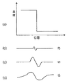
さらに、例えば原画像信号を多重解像度変換した場合の比較的高解像度レベルの画像など比較的高周波数帯域の画像においては詳細なエッジ情報が表現され、中間周波数帯域の画像においては中間周波数帯域のエッジ情報が、低周波数帯域の画像においては低周波数帯域の大きなエッジ情報が表現されることとなる。一般的に各周波数帯域の画像が持っているエネルギは高周波数帯域ほど小さくなるが、ノイズのエネルギは周波数帯域に依存しないという特性があるため、低周波数帯域の画像ほどS/Nが良好なものとなる。ここで、原画像におけるノイズが混入していない部分(図8(a)参照)は、いずれの帯域制限画像においてもエッジ部分にのみ信号を有することとなるため(図8(b)〜(d)参照)、比較的高周波数帯域の画像において、画素ベクトルを求めた画素を含む所定領域における画素値の分散値が小さければ、低周波帯域画像の画素ベクトルを参照しなくてもその画素ベクトルを求めた注目画素は平坦部にあると見なすことができる。
【0062】
一方、原画像におけるノイズが混入した部分(図9(a))は、高周波数帯域の画像においてはノイズの影響により画素ベクトルの方向が乱されて分散値が大きくなるが(図9(b))、低周波数帯域となるほど信号に対するノイズの影響が小さくなって分散値が小さくなる(図9(c)、(d))。したがって、一の帯域制限画像において画素ベクトルを求めた一の画素を含む所定領域における画素値の分散値が大きい場合は、低周波数帯域の画像における対応する画素ベクトルを参照しなければ、その画素ベクトルを求めた画素が平坦部にあるものであるのかエッジ部分にあるものであるのかが分からない。このため、一の帯域制限画像において上記分散値が大きい場合は、低周波数帯域の画像を参照して、画素ベクトルを低周波帯域画像における対応する画素の画素ベクトルと一致させることにより、平坦部の画素ベクトルはより平坦部を表すものとして、エッジ部分の画素ベクトルはよりエッジ部分を表すものとして修正されることとなる。したがって、修正された画素ベクトルに基づけば、ノイズ成分およびエッジ成分を正確に分離することができることとなる。
【0063】
本発明による第2の画像処理方法および装置によれば、第1の画像処理方法および装置と同様に、各帯域制限画像の各画素における画素ベクトルが算出される。また、本発明による第2の画像処理方法および装置によれば、画素ベクトルの方向に基づいて各帯域制限画像を平滑化している。
【0064】
ここで、原画像にノイズが混入している場合、画像中のエッジ成分にもノイズが含まれることとなるが、第2の方法のように、画素ベクトルあるいは前述の各方法を用いて修正された画素ベクトルの方向に基づいて帯域制限画像信号を平滑化して平滑化帯域制限画像信号を得、該平滑化帯域制限画像信号に基づいて処理済み画像信号を得る方法を用いれば、エッジ成分を失うことなくエッジ上のノイズを抑制でき、またエッジ以外の平坦部のノイズも抑制できるので、最終的には、エッジ上のノイズが目立たなくなるとともに、平坦部におけるノイズも目立たなくなる。
【0065】
また、平滑化の後、さらに、画素ベクトルの大きさに基づいて、平滑化帯域制限画像信号のノイズ成分およびエッジ成分を分離し、平滑化帯域制限画像信号に対して、ノイズ成分に対する平滑化処理および/またはエッジ成分に対する強調処理を施して処理済帯域制限画像信号を得るようにすれば、エッジ上のノイズを目立たせることなくエッジ強調を行なうことができ、また平坦部のノイズを一層低減することができるので、一層高画質の画像を再現することができる。
【0066】
【発明の実施の形態】
以下図面を参照して本発明の実施形態について説明する。
【0067】
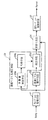
図1は本発明の第1の実施形態による画像処理装置の構成を示す概略ブロック図である。図1に示すように本発明の第1の実施形態による画像処理装置は、放射線画像を表す原画像信号Sorgに対してウェーブレット変換を施すウェーブレット変換手段1と、ウェーブレット変換手段1において得られたウェーブレット変換係数信号から後述するようにして画素ベクトルを算出する画素ベクトル算出手段2と、画素ベクトル算出手段2において算出された画素ベクトルを修正する画素ベクトル修正手段3と、画素ベクトル修正手段3において修正された修正画素ベクトルに基づいてウェーブレット変換係数信号を平滑化して平滑化信号を得る平滑化手段4と、修正された画素ベクトルに基づいて平滑化信号からノイズ成分とエッジ成分とを分離する分離手段5と、分離手段5における分離結果に基づいて平滑化信号のエッジ部分を強調し、ノイズ部分を平滑化する処理を施す処理手段6と、処理手段6において処理が施された平滑化信号に対して逆ウェーブレット変換処理を施して処理済み画像信号Sprocを得る逆ウェーブレット変換手段7とを備える。
【0068】
なお、本実施形態は、例えば特開昭55-12492号や特開昭56-11395号等に記録されている蓄積性蛍光体シートを利用した放射線画像情報記録再生システムにおいて、蓄積性蛍光体シートに記録された人体の放射線画像をレーザビーム走査によりデジタル画像信号として読み取ったものを対象としている。なお、放射線画像の読み取りは、図2に示すように、蓄積性蛍光体シート10に対して主走査方向(横方向)にレーザビームを走査させながらシート10を副走査方向(縦方向)に移動させてシート10を2次元走査することにより行なわれたものである。
【0069】
図3はウェーブレット変換手段1の構成を示す概略ブロック図である。なお、本実施形態においては、ウェーブレット変換の各係数が直交する直交ウェーブレット変換を行なうものであり、ウェーブレット変換手段1は、本発明の帯域制限画像信号作成手段として機能するものである。また、逆ウェーブレット変換手段7は、本発明の画像信号生成手段として機能するものである。
【0070】
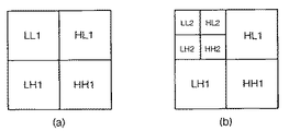
まず、図3に示すように原画像信号Sorgに対してウェーブレット変換部11においてウェーブレット変換が施される。図4はウェーブレット変換部11において行なわれる処理を示すブロック図である。図4に示すように、原画像信号Sorg(信号LLk)の主走査方向に基本ウェーブレット関数H,Gによりフィルタリング処理を行なうとともに、主走査方向の画素を1画素おきに間引き(図中↓2で表す)、主走査方向の画素数を1/2にする。ここで、関数Hはハイパスフィルタであり、関数Gはローパスフィルタである。さらに、この画素が間引かれた信号のそれぞれに対して副走査方向に関数H,Gによりフィルタリング処理を行なうとともに、副走査方向の画素を1画素おきに間引き、副走査方向の画素数を1/2にして、ウェーブレット変換係数信号(以下単に信号とすることもある)HH1,HL1,LH1,LL1(HHk+1,HLk+1,LHk+1,LLk+1)を得る。ここで、信号LL1は原画像の縦横を1/2に縮小した画像を表し、信号HL1、LH1およびHH1はそれぞれ原画像の1/2縮小画像において縦エッジ、横エッジおよび斜めエッジ成分の画像を表すものとなる。
【0071】
次に、信号LL1に対してさらにウェーブレット変換部11においてウェーブレット変換が施されて、信号HH2,HL2,LH2,LL2が得られる。ここで、信号LL2は原画像の縦横を1/4に縮小した画像を表し、信号HL2、LH2およびHH2はそれぞれ原画像の1/4縮小画像において縦エッジ、横エッジおよび斜めエッジ成分の画像を表すものとなる。
【0072】
以下、上記と同様にして、各周波数帯域において得られるウェーブレット変換係数信号LLkに対するウェーブレット変換をn回繰り返すことによりウェーブレット変換係数信号HH1〜HHn,HL1〜HLn,LH1〜LHn,LL1〜LLnを得る。ここで、n回目のウェーブレット変換により得られるウェーブレット変換係数信号HHn,HLn,LHn,LLnは、原画像信号Sorgと比較して主副各方向の画素数が(1/2)n となっているため、各ウェーブレット変換係数信号はnが大きいほど周波数帯域が低く、原画像データの周波数成分のうち低周波数成分を表すデータとなる。したがって、ウェーブレット変換係数信号HHk(k=0〜n、以下同様)は、原画像信号Sorgの主副両方向の周波数の変化を表すものであり、kが大きいほど低周波信号となる。またウェーブレット変換係数信号HLkは原画像信号Sorgの主走査方向の周波数の変化を表すものであり、kが大きいほど低周波信号となる。さらにウェーブレット変換係数信号LHkは原画像信号Sorg の副走査方向の周波数の変化を表すものであり、kが大きいほど低周波信号となる。
【0073】
ここで、図5にウェーブレット変換係数信号を複数の周波数帯域毎に示す。なお、図5においては便宜上2回目のウェーブレット変換を行った状態までを表すものとする。なお、図5において信号LL2は原画像を主副各方向が1/4に縮小した画像を表すものとなっている。
【0074】
なお、ウェーブレット変換係数信号HHk,HLk,LHk,LLk(k=1〜n)のうち、信号HHk,HLk,LHkはその周波数帯域におけるエッジ成分を表すものであり、換言すれば原画像における特定の周波数帯域(帯域制限画像特性)を有する画像を表すもの、すなわち主にその周波数帯域における画像のコントラストを表すものとなっている。また、ある周波数帯域におけるウェーブレット変換係数信号HHk,HLk,LHkの画素の総和は0に近い値となる。また、ウェーブレット変換係数信号LLkは上述したように原画像を縮小した画像を表すものとなっている。なお、本実施形態においては、ウェーブレット変換係数信号HHk,HLk,LHkを帯域制限画像信号と称し、ウェーブレット変換係数信号LLkを解像度信号と称し、帯域制限画像信号および解像度信号を総称してウェーブレット変換係数信号と称するものとする。
【0075】
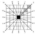
画素ベクトル算出手段2においては以下のようにして画素ベクトルが算出される。図6は画素ベクトルの算出方法を説明するための図である。なお、この画素ベクトルの算出は全周波数帯域のウェーブレット変換係数信号により表される画像における全画素について行なわれる。ある画素を注目画素(図6において黒色で示す)とした場合において、注目画素を中心とした7×7の領域を設定する。そしてこの領域内における注目画素近傍の48画素について、注目画素を中心とした0〜15の16方向における一定長さ分(図6においては3画素分、例えば2の方向における斜線画素)の画素値の平均値を算出し、この平均値と注目画素の画素値との差が最も小さい方向を決定する。なお、図7に示すように注目画素の近傍8画素を用いて、8方向における注目画素と隣接画素との差を求め、この差が最も小さい方向を決定してもよい。このようにして求められた方向は濃度の傾きが最も小さい方向であり、等信号線すなわち信号勾配の法線方向を向くものである。そして、この方向と上述したように求められた差の逆数を大きさに持つベクトルを画素ベクトルとして求める。したがって、この画素ベクトルは、等信号線の方向において濃度差が小さいほど大きいものとなる。なお、上記差が0の場合は画素ベクトルの大きさは無限大となってしまうため、画素ベクトルの大きさに上限値(例えば8ビットの場合は255)を設定することが好ましい。
【0076】
なお、上述した平均値と注目画素の画素値との差(あるいは近傍画素と注目画素との差、以下単に差とする)が最も大きい方向は信号勾配方向となり、この方向に画素ベクトルを求めることもできる。この場合、画素ベクトルの大きさは上記差をそのまま用いることができる。なお、本実施形態においては画素ベクトルは等信号線方向を向き、画素ベクトルの大きさは上記差の逆数として説明する。
【0077】
図1に示すように、画素ベクトル修正手段3は、一の周波数帯域(本例においては一の解像度レベル)における帯域制限画像の注目画素(一の画素)を含む所定領域の分散値を算出する分散値算出手段3aと、該分散値に基づいて注目画素の画素ベクトルを修正するか否かを判断する判断手段3bと、注目画素の画素ベクトルを修正すると判断された場合は、該注目画素における画素ベクトルを、前記一の周波数帯域よりも低周波数帯域の画像(本例においては解像度レベルが低下した低解像度画像)における注目画素に対応する画素の画素ベクトルに基づいて修正する修正手段3cとからなる構成である。
【0078】
この画素ベクトル修正手段3においては以下のようにして分散値が算出された後画素ベクトルが修正される。原画像信号をウェーブレット変換した場合、比較的高周波数帯域の画像においては詳細なエッジ情報が表現され、中間周波数帯域の画像においては中間周波数帯域のエッジ情報が、低周波数帯域の画像においては低周波数帯域の大きなエッジ情報が表現されることとなる。一般的に各周波数帯域の画像が持っているエネルギは高周波数帯域ほど小さくなるが、ノイズのエネルギは周波数帯域に依存しないという特性があるため、低周波数帯域の画像ほどS/Nが良好なものとなる。ここで、原画像におけるノイズが混入していない部分(図8(a)参照)は、いずれの帯域制限画像においてもエッジ部分にのみ信号を有することとなるため(図8(b)〜(d)参照)、比較的高帯域制限画像において、画素ベクトルを求めた画素を含む所定領域における画素値の分散値が小さければ、低周波帯域画像の画素ベクトルを参照しなくてもその画素ベクトルを求めた注目画素は平坦部にあると見なすことができる。
【0079】
一方、原画像におけるノイズが混入した部分(図9(a))は、高帯域制限画像においてはノイズの影響により画素ベクトルの方向が乱されて分散値が大きくなるが(図9(b))、低周波数帯域となるほど信号に対するノイズの影響が小さくなって分散値が小さくなる(図9(c)、(d))。したがって、高帯域制限画像において画素ベクトルを求めた注目画素を含む所定領域における画素値の分散値が大きい場合は、低周波数帯域の画像における対応する画素ベクトルを参照しなければ、その画素ベクトルを求めた注目画素が平坦部にあるものであるのかエッジ部分にあるものであるのかが分からない。
【0080】
このため、分散値算出手段3aは、画素ベクトルを求めた注目画素を中心とする例えば3×3の領域内における画素値の分散値を全画素について求める。判断手段3bは、分散値算出手段3aによって求められた分散値に基づいて、分散値が同一周波数帯域の画像における他の領域と比較して相対的に小さい場合には、そこは平坦部と見なして画素ベクトルの修正を行なう必要がないと判断する一方、分散値が同一周波数帯域の画像における他の領域と比較して相対的に大きい場合には、そこは平坦部であるかエッジ部分であるか分からないため、画素ベクトルの修正を行なう必要があると判断する。修正手段3cは、判断手段3bの判断結果に基づいて、画素ベクトルの修正を行なう必要がないと判断されたとき(分散値が他の領域と比較して相対的に小さいとき)には、画素ベクトル算出手段2において求められた画素ベクトルをそのまま修正画素ベクトルとする一方、修正を行なう必要があると判断されたとき(分散値が他の領域と比較して相対的に大きいとき)には、低周波帯域画像(本例においては解像度レベルが低下した低解像度画像)における対応する画素の画素ベクトルをその注目画素の修正画素ベクトルとする。これにより、平坦部の画素ベクトルはより平坦部を表すものとして、エッジ部分の画素ベクトルはよりエッジ部分を表すものとして修正されることとなり、その画素ベクトルを求めた注目画素が平坦部にあるかエッジ部分にあるかの確度を向上させることができる。
【0081】
なお、画素ベクトル修正手段3においては、画素ベクトルを算出した際の注目画素とその近傍の画素との差分値を分散値として求めてもよい。この差分値としては、例えば注目画素近傍8画素から画素ベクトルを求めた場合は、注目画素と近傍8画素の差の和、あるいはこの差の平均値等としてもよい。
【0082】
平滑化手段4においては修正画素ベクトルに基づいて以下のようにして平滑化処理が行なわれる。なお、平滑化処理は各周波数帯域の帯域制限画像信号HHk,HLk,LHkおよび最低解像度の解像度信号LLnに対して行なわれる。図10は平滑化手段4における平滑化処理を説明するための図である。注目画素を中心とする3×3の領域において各画素の画素値が図10(a)に示す値を有する場合、画素ベクトル(修正画素ベクトル)は図10(b)に示すものとなる。そして、図10(b)に斜線で示すように注目画素と画素ベクトル方向にある画素および画素ベクトル方向と反対方向にある画素を用いて平滑化フィルタによりフィルタリングを行なう。ここで、平滑化フィルタとしては、方向性を持っているフィルタであればどのようなフィルタを用いてもよく、例えば図11(a)に示す平均値フィルタや図11(b)に示す平滑化フィルタを用いることができる。図11(a)に示す平均値フィルタを用いた場合、図10(a)に示す画素値は図12(a)に示すように平滑化されて注目画素の画素値は101となる。また、図11(b)に示す平滑化フィルタを用いた場合、図12(b)に示すように注目画素の画素値は141となるように平滑化される。このように平滑化を行なうことにより、例えばエッジ上にノイズが混入されている場合に、そのノイズを目立たなくすることができる。また、エッジ上でなくとも平坦部において平滑化を行なうことにより、平坦部にあるノイズを目立たなくすることができる。なお、平滑化されたウェーブレット変換係数信号を平滑化信号(平滑化帯域制限画像信号)とする。
【0083】
なお、ここでは画素ベクトル方向にある画素および画素ベクトル方向と反対方向にある画素を用いて平滑化を行なっているが、画素ベクトル方向にある画素のみを用いて平滑化を行なってもよい。この場合、図10(a)に示す注目画素は99(=(101+98)/2)の値を有するように平滑化される。
【0084】
また、注目画素の近傍48画素から画素ベクトルを求めた場合において、画素ベクトルの方向が図13に示す方向であった場合には、図13の斜線に示すように注目画素および画素ベクトル方向の画素(さらには画素ベクトルと反対方向の画素)を用いて平滑化を行えばよい。具体的には、図13に示す斜線で示す全7画素における画素値の平均値を注目画素の画素値とすればよい。
【0085】
分離手段5においては画素ベクトルや修正画素ベクトルの大きさに基づいて、以下のようにしてエッジ成分とノイズ成分とが分離される。すなわち、上記画素ベクトル修正手段3において求められた修正画素ベクトルが大きい画素についてはエッジ成分にあるものと見なし、修正画素ベクトルが小さい画素については平坦部すなわちノイズ成分にあるものと見なし、各周波数帯域の平滑化信号により表される画像の各画素をラベリングすることにより、エッジ成分とノイズ成分とを分離する。
【0086】
なお、画素ベクトルが小さい場合には、注目画素は平坦部すなわちノイズ成分にあるものと見なせるが、微小エッジ部分にある可能性もある。このため、分離手段5においては、画素ベクトルが小さい場合には注目画素の画素ベクトルとその近傍画素の画素ベクトルの方向とを参照し、図14(a)に示すように近傍の画素ベクトルが注目画素の画素ベクトルと同一方向を向いている場合にはその注目画素をエッジ成分にあるものと見なし、図14(b)に示すように近傍の画素ベクトルが注目画素の画素ベクトルと異なる方向を向いている場合には、その注目画素をノイズ成分にあるものと見なすようにすることが好ましい。なお、図14においては各画素の数字は画素ベクトルの方向(図7参照)を示すものである。
【0087】
処理手段6においては分離手段5において求められたラベリングの結果に基づいてエッジ成分にあると見なされた画素については画素値を大きくする強調処理を、ノイズ成分にあると見なされた画素については画素値を小さくする平滑化処理を行なう。なお、この処理は分離手段5において求められたエッジ成分およびノイズ成分に関する情報により、画素そのものを変更する処理すなわち各帯域制限画像における局所的なコントラストを変更するための処理であるため、各周波数帯域における画像のコントラストを表す平滑化された帯域制限画像信号(平滑化信号)HHk,HLk,LHkに対してのみ処理が行なわれ、処理済み帯域制限画像信号HHk′,HLk′,LHk′(k=1〜n)が得られる。なお、解像度信号については平滑化手段4において平滑化処理が施されているため、平滑化処理が施された解像度信号を処理済み解像度信号LLn′とする。なお、これらを総称して処理済み信号HHk′,HLk′,LHk′(k=1〜n),LLn′とする。
【0088】
また、処理手段6においてエッジ成分と見なされた画素を強調する際は、画素値に応じて強調の程度を変更するようにしてもよい。すなわち、画素値が大きい場合にさらに画素値を大きくする強調処理を施すと、エッジが強調されすぎて処理済み画像信号Sprocを再生することにより得られる画像にオーバーシュートあるいはアンダーシュートが発生するおそれがある。したがって、画素値が大きい場合にはその強調の程度を低くすることによりオーバーシュート、アンダーシュートの発生を防止することができる。
【0089】
次いで、上記のようにして得られた処理済み信号HHk′,HLk′,LHk′,LLn′に対して逆ウェーブレット変換手段7において逆ウェーブレット変換が施される。図15は、逆ウェーブレット変換手段7の構成を示す概略ブロック図である。図15に示すように、最低周波数帯域の処理済み信号HHn′,HLn′,LHn′,LLn′に対して逆ウェーブレット変換部12において逆ウェーブレット変換を施して処理済み信号LLn−1′を得る。図16は逆ウェーブレット変換部12において行なわれる処理を示すブロック図である。図16に示すように処理済み信号LLn′(LLk′)および処理済み信号LHn′(LHk′)の副走査方向に対して画素間に1画素分の間隔をあける処理を行なうとともに(図中↑2で表す)、関数G,Hに対応する逆ウェーブレット変換関数G′,H′によりフィルタリング処理を副走査方向に施してこれらを加算し、さらに加算により得られた信号(第1の加算信号とする)の主走査方向に対して画素間に1画素分の間隔をあける処理を行なうとともに、関数G′によりフィルタリング処理を主走査方向に施して第1の信号を得る。一方、信号HLn′(HLk′)および信号HHn′(HHk′)の副走査方向に対して画素間に1画素分の間隔をあける処理を行なうとともに、関数G′,H′によりフィルタリング処理を副走査方向に施してこれらを加算し、さらに加算により得られた信号(第2の加算信号とする)の主走査方向に対して画素間に1画素分の間隔をあける処理を行なうとともに、関数H′によりフィルタリング処理を主走査方向に施して第2の信号を得る。そして第1および第2の信号を加算して処理済み信号LLn−1′(LLk−1′)を得る。
【0090】
次に、処理済み信号HHn−1′,HLn−1′,LHn−1′,LLn−1′に対して上記と同様に逆ウェーブレット変換部12において逆ウェーブレット変換を行なって、処理済み信号LLn−2′を得る。そして、以下上記と同様にして逆ウェーブレット変換を最高周波数帯域まで繰り返すことにより処理済み画像信号Sprocが得られる。
【0091】
次いで、第1の実施形態の動作について説明する。図17は第1の実施形態の動作を示すフローチャートである。まず、原画像信号Sorgに対してウェーブレット変換手段1においてウェーブレット変換が行なわれて各周波数帯域毎のウェーブレット変換係数信号が得られる(ステップS1)。次に、各ウェーブレット変換係数信号に基づいて画素ベクトル算出手段2において上述したように画素ベクトルが算出される(ステップS2)。画素ベクトルの算出の後、画素ベクトル修正手段3において画素ベクトルが修正されて修正画素ベクトルが求められる(ステップS3)。そして、修正画素ベクトルに基づいて、各ウェーブレット変換係数信号に対して平滑化手段4において平滑化処理が施されて平滑化信号が得られる(ステップS4)。
【0092】
次に分離手段5において画素ベクトル修正手段3において求められた修正画素ベクトルに基づいて、平滑化信号に対してノイズ成分とエッジ成分とを分離する処理が施される(ステップS5)。そして、処理手段6において分離手段5における分離の結果に基づいて、平滑化された帯域制限画像信号に対してエッジ成分と見なされた画素の画素値を大きくする強調処理、およびノイズ成分と見なされた画素の画素値を小さくする平滑化処理が行なわれ、処理済み信号HHk′,HLk′,LHk′,LLn′が得られる(ステップS6)。そして、逆ウェーブレット変換手段7において処理済み信号HHk′,HLk′,LHk′,LLn′に対して逆ウェーブレット変換を施して処理済み画像信号Sprocが得られる(ステップS7)。
【0093】
ここで、各周波数帯域において得られる処理済み信号HHk′,HLk′,LHk′,LLn′はノイズ成分が低減され、エッジ成分が強調される処理が施されているため、最終的に得られる処理済み画像信号Sprocにおいても、ノイズ成分が低減され、エッジ成分が強調されたものとなる。したがって、ノイズが目立たなくなるとともにエッジが明瞭となった高画質の画像を再現可能な処理済み画像信号Sprocを得ることができる。
【0094】
また、原画像にノイズが混入している場合、エッジ成分にもノイズが含まれることとなる。この場合、画素ベクトルに基づいてノイズ成分およびエッジ成分を分離してエッジ成分を強調すると、エッジ成分に含まれるノイズをも強調してしまうこととなる。本実施形態においては、画素ベクトルや修正画素ベクトルの方向に基づいて平滑化手段4において平滑化を行なっているため、エッジ成分を失うことなくエッジ上のノイズ成分を抽出でき、またエッジ以外の平坦部のノイズも抽出できるので、最終的には、エッジ上のノイズが目立たなくなるとともに、平坦部におけるノイズも目立たなくなり、高画質の画像を再現できる。
【0095】
また、画素ベクトルの大きさに基づいて、平滑化された帯域制限画像信号(すなわち平滑化信号)のノイズ成分およびエッジ成分を分離した後、平滑化信号に対して、ノイズ成分に対する平滑化処理やエッジ成分に対する強調処理を施して処理済み帯域制限画像信号を得、この処理済み帯域制限画像信号を逆ウェーブレット変換して処理済み画像信号Sprocを得ているので、エッジ上のノイズを目立たせることなくエッジ強調を行なうことができ、また平坦部のノイズを一層低減することができるので、一層高画質の画像を再現することができる。
【0096】
なお、上記第1の実施形態においては、処理手段6においてエッジ成分にあると見なされた画素の強調およびノイズ成分にあると見なされた画素の平滑化の双方の処理を行なっているが、いずれか一方の処理のみを行なうことによっても、ノイズが目立たなくなりエッジが目立つような画像を再現することができる。
【0097】
また、上記第1の実施形態においては、ウェーブレット変換係数信号を平滑化手段4において平滑化しているが、これに限定されるものではなく、図18に示す第2の実施形態のように、第1の実施形態における平滑化手段4を取り除いた構成とすることにより、平滑化することなく、分離手段5においてウェーブレット変換係数信号に対して直接エッジ成分とノイズ成分とを分離する処理を施し、平滑化されていない帯域制限画像信号に対して処理手段6において処理を行なうようにしてもよい。なお、この場合、処理手段6においてエッジ成分にあると見なされた画素に対して強調処理を行なうと、エッジ成分に含まれるノイズを強調するという問題が生じ得るので、第1の実施形態に示した平滑化手段4を備えたものの方が、画質の上で有利である。
【0098】
次いで、本発明の第3の実施形態について説明する。図19は本発明の第3の実施形態による画像処理装置の構成を示す概略ブロック図である。図19に示すように本発明の第3の実施形態による画像処理装置は、放射線画像を表す原画像信号Sorgに対してウェーブレット変換を施すウェーブレット変換手段21と、ウェーブレット変換手段21において得られたウェーブレット変換係数信号から画素ベクトルを算出する画素ベクトル算出手段22と、画素ベクトル算出手段22において算出された画素ベクトルを修正する画素ベクトル修正手段23と、画素ベクトル修正手段23において修正された修正画素ベクトルに基づいてウェーブレット変換係数信号を平滑化して平滑化信号を得る平滑化手段24と、平滑化手段24において得られた平滑化信号に対して逆ウェーブレット変換処理を施して処理済み画像信号Sprocを得る逆ウェーブレット変換手段27とを備える。上記第1の実施形態との違いは、分離手段5を設けておらず、平滑化手段24により得られる平滑化信号を逆ウェーブレット変換手段27において逆ウェーブレット変換して処理済み画像信号Sprocを得る構成とした点である。
【0099】
なお、ウェーブレット変換手段21、画素ベクトル算出手段22、画素ベクトル修正手段23、平滑化手段24および逆ウェーブレット変換手段27において行なわれる処理は上記第1の実施形態におけるウェーブレット変換手段1、画素ベクトル算出手段2、画素ベクトル修正手段3、平滑化手段4および逆ウェーブレット変換手段7において行なわれる処理と同一であるため、ここでは詳細な説明は省略する。
【0100】
図20は第3の実施形態の動作を示すフローチャートである。図20に示すように、まず、原画像信号Sorgに対してウェーブレット変換手段21においてウェーブレット変換が行なわれて各周波数帯域毎のウェーブレット変換係数信号が得られる(ステップS11)。次に、各ウェーブレット変換係数信号に基づいて画素ベクトル算出手段22において上述したように画素ベクトルが算出される(ステップS12)。画素ベクトルの算出の後、画素ベクトル修正手段23において画素ベクトルが修正されて修正画素ベクトルが求められる(ステップS13)。そして、修正画素ベクトルに基づいて、各ウェーブレット変換係数信号に対して平滑化手段4において平滑化処理が施されて平滑化信号が得られる(ステップS14)。そして、平滑化信号を処理済み信号とし、逆ウェーブレット変換手段27において処理済み信号に対して逆ウェーブレット変換を施して処理済み画像信号Sprocが得られる(ステップS15)。
【0101】
ここで、原画像にノイズが混入している場合、画像中のエッジ成分にもノイズが含まれることとなる。このため、画素ベクトルに基づいて平滑化を行なうことにより、エッジ成分に含まれるノイズが目立たなくなるとともに、平坦部におけるノイズも目立たなくなる。したがって、第3の実施形態のように各周波数帯域のウェーブレット変換係数信号に対して平滑化処理を施すことにより、各帯域制限画像においてノイズ成分が目立たなくなり、エッジ成分がより目立つようになる。したがって、平滑化された帯域制限画像信号を逆ウェーブレット変換することにより得られる処理済み画像信号Sprocにおいても、エッジ成分が目立ちノイズ成分が目立たなくなるため、処理済み画像信号Sprocに基づいて高画質の画像を再現することができる。
【0102】
ここで、第3の実施形態においては、第1の実施形態と同様に、画素ベクトルや修正画素ベクトルの方向に基づいて平滑化手段24において平滑化を行なっているため、エッジ成分を失うことがなく、またエッジ以外の平坦部のノイズを抑制することができるので、エッジが保存されたノイズの目立たない、高画質の画像を再現できる。
【0103】
なお、上記第1〜第3の実施形態においては、画素ベクトル算出手段2,22において、注目画素の画素値とその近傍画素の画素値の平均値(あるいは近傍画素の画素値)との差が最も小さい方向を画素ベクトルの方向として求めているが、上記差が2番目に小さい方向を第2の画素ベクトルとして求めてもよい。あるいは信号勾配方向に画素ベクトルを求める場合には、上記差が2番目に大きい方向を第2の画素ベクトルとして求めてもよい。このように第2の画素ベクトルを求めることにより、例えば図21(a)に示すようにエッジ成分が屈曲して存在する場合においては図21(b)に示すように2つの画素ベクトルが求められる。そして、平滑化手段4,24において第1および第2の画素ベクトルの双方を用いて平滑化を行なうことにより、エッジ成分をその方向性を維持してより正確に平滑化することができる。
【0104】
また、画像に含まれる比較的大きなエッジは低周波帯域画像においても残るが、ノイズについては低周波帯域画像ほど小さくなるものである。このため、ある周波数帯域における帯域制限画像の一の画素における画素ベクトルの方向を、低周波数帯域の画像における一の画素に対応する画素の画素ベクトルの方向と同じにすることにより、その画素がエッジ成分にある場合はその画素ベクトルはよりエッジ成分を表すものとなる。一方、その画素がノイズ成分にある場合は低周波帯域画像の方が細かなノイズが小さくなることから、画素ベクトルはランダムな方向を向きかつ大きさはさらに小さくなるため、その画素ベクトルはより平坦部すなわちノイズ成分を表すものとなる。したがって、上記第1〜第3の実施形態においては、画素ベクトル修正手段3,23において、上記分散値に基づく処理に代えてある周波数帯域のある画素における画素ベクトルの方向を、さらに低周波数帯域の画像における上記ある画素に対応する画素の画素ベクトルの方向と同じになるように修正することにより、その画素がエッジ成分にあるかノイズ成分にあるかの確度を向上させることができる。特に第1および第2の実施形態においては、これにより分離手段5におけるノイズ成分およびエッジ成分の分離を正確に行なうことができる。
【0105】
さらに、上記第1〜第3の実施形態においては、画素ベクトル修正手段3,33において画素ベクトルを修正しているが、画素ベクトル算出手段2,22において算出された画素ベクトルをそのまま用いて平滑化およびノイズ成分とエッジ成分との分離を行なってもよい。
【0106】
一方、画像信号の保存形式としては、JPEG、GIF、TIFF等種々の形式が存在するが、近年画像信号を解像度毎に階層的に分解し、各階層毎のデータ(階層データ)を符号化して圧縮保管するファイル形式が提案されている。このファイル形式は、具体的には原画像信号をウェーブレット変換等により複数の解像度毎の階層データに分解し、この分解された各解像度毎の階層データを階層順に符号化して1つのファイルとして圧縮して保管するものである。したがって、このようなファイル形式の画像信号を作成する場合に、本発明による処理を同時に行なうことにより、ノイズが低減されかつエッジが目立つ画像を再現可能なファイル形式の画像データを作成することができる。また、本発明による処理と、画像信号を階層化して圧縮する処理とを同時に行なうことができるため、効率よく画像信号を圧縮することができる。
【0107】
また、例えば人体の胸部のように軟部および骨部から構成された被写体に互いにエネルギの異なる放射線を照射して複数の放射線画像を得、これら複数の放射線画像を読み取ってこれら複数の放射線画像のそれぞれを表す複数の画像信号を得、これら複数の画像信号に基づいてエネルギーサブトラクション処理を行なって被写体の主として軟部が記録された軟部画像を表す軟部画像信号もしくは被写体の主として骨部が記録された骨部画像を表す骨部画像信号を求め、求められた軟部画像もしくは骨部画像を観察の対象とする場合がある。この場合において、軟部画像もしくは骨部画像のノイズ成分を低減するために、骨部画像信号に対して平滑化処理を施して第1の平滑化画像信号を求め、原画像信号から第1の平滑化画像信号を減算することにより軟部画像を表す軟部画像信号を求める第1の処理を行ない、さらに軟部画像信号に対して平滑化処理を施して第2の平滑化画像信号を求め、原画像信号から第2の平滑化画像信号を減算することにより、ノイズが除去された骨部画像信号を求める第2の処理を行ない、上記第1および第2の処理を繰り返すことにより、ノイズ成分を低減するようにしたエネルギーサブトラクション画像生成方法が提案されている(例えば特開平5-236351号)。ここで、このようなエネルギーサブトラクション画像生成方法において、平滑化画像を求める際に、本発明による処理を施すようにしてもよいものである。このように、エネルギーサブトラクション画像生成方法において、本発明による処理を施すことによって平滑化画像信号を求めることにより、ノイズ成分のみが低減されてエッジ成分を目立つものとすることができ、これにより高画質の軟部画像もしくは骨部画像を得ることができる。
【0108】
また、上記第1〜第3の実施形態においては、原画像信号Sorg に対してウェーブレット変換を施すことにより得られる信号に対して、上述したような画素ベクトルに基づく処理を施しているが、ウェーブレット変換のみならずラプラシアンピラミッド等、原画像信号Sorg を多重解像度変換する手法において得られる周波数帯域毎の帯域制限画像信号、あるいは多重解像度変換処理以外の方法を利用して得た帯域制限画像信号に対しても、上記と同様に処理を施すことができる。
【図面の簡単な説明】
【図1】本発明の第1の実施形態による画像処理装置の構成を示す概略ブロック図
【図2】本発明に用いられる原画像信号の読み取り方式を表す図
【図3】ウェーブレット変換手段の構成を示す概略ブロック図
【図4】ウェーブレット変換部において行なわれる処理を示す図
【図5】ウェーブレット変換係数信号を複数の周波数帯域毎に示す図
【図6】画素ベクトルの算出を説明するための図(その1)
【図7】画素ベクトルの算出を説明するための図(その2)
【図8】ウェーブレット変換係数信号を示す図(その1)
【図9】ウェーブレット変換係数信号を示す図(その2)
【図10】平滑化を説明するための図(その1)
【図11】平滑化フィルタを示す図
【図12】平滑化された画素値を示す図
【図13】平滑化を説明するための図(その2)
【図14】分離手段における画素ベクトルの参照結果を示す図
【図15】逆ウェーブレット変換手段の構成を示す概略ブロック図
【図16】逆ウェーブレット変換部において行なわれる処理を示す図
【図17】第1の実施形態の動作を示すフローチャート
【図18】本発明の第2の実施形態による画像処理装置の構成を示す概略ブロック図
【図19】本発明の第3の実施形態による画像処理装置の構成を示す概略ブロック図
【図20】第3の実施形態の動作を示すフローチャート
【図21】平滑化の他の例を説明するための図
【符号の説明】
1,21 ウェーブレット変換手段
2,22 画素ベクトル算出手段
3,23 画素ベクトル修正手段
4,24 平滑化手段
5 分離手段
6 処理手段
7,27 逆ウェーブレット変換手段
11 ウェーブレット変換部
12 逆ウェーブレット変換部[0001]
BACKGROUND OF THE INVENTION
The present invention records an image processing method and apparatus for performing noise reduction processing and processing for emphasizing a desired structure on an original image signal representing an original image, and a program for causing a computer to execute the image processing method. The present invention relates to a computer-readable recording medium.
[0002]
[Prior art]
In various fields, an image signal representing an image is obtained, and after appropriate image processing is performed on the image signal, the image is reproduced and displayed. For example, in order to improve the diagnostic performance of a radiographic image, a method of performing frequency enhancement processing such as blur mask processing on an image signal has been proposed by the present applicant (Japanese Patent Laid-Open No. Sho 55-163772). This frequency processing is a process for adding a signal obtained by subtracting a blur mask signal from an image signal representing an original image and multiplying the degree of enhancement, thereby enhancing a predetermined spatial frequency component in the image. is there.
[0003]
On the other hand, as a method for processing the above-described image signal, the image is converted into a multi-resolution image for each of a plurality of frequency bands, predetermined processing is performed on the image in each frequency band, and this is again processed by inverse multi-resolution. A method of multi-resolution conversion has been proposed for obtaining a final processed image by conversion. As this multi-resolution conversion method, methods such as wavelet conversion and Laplacian pyramid are known.
[0004]
Here, the wavelet transform will be described. The wavelet transform was developed as a frequency analysis method in recent years and has been applied to stereo pattern matching, data compression, etc. (OLIVIER RIOUL and MARTIN VETTERLI; Wavelets and Signal Processing, IEEE SP MAGAZINE, P.14-38, OCTOBER 1991, Stephane Mallat; Zero-Crossings of a Wavelet Transform, IEEE TRANSACTIONS ON INFORMATION THEORY, VOL.37, NO.4, P.1019-1033, JULY 1991).
[0005]
On the other hand, a method called Laplacian pyramid is described in, for example, Japanese Patent Laid-Open Nos. 5-244508, 6-96200, and 6-301766, and this Laplacian pyramid is approximated by a Gaussian function with respect to the original image. After performing mask processing with a simple mask, the image is subsampled and the number of pixels is thinned out to halve to obtain a blurred image that is ¼ the size of the original image. The pixel having the value of 0 is interpolated to return to the original size image, and this image is further subjected to mask processing using the mask described above to obtain a blurred image, and this blurred image is subtracted from the original image to obtain the original image. A detailed image representing a predetermined frequency band is obtained. By repeating this process for the blurred image obtained, 1/2 of the original image is obtained. 2N N blur images of the size of are created. Here, since sampling is performed on an image subjected to mask processing using a mask approximated by a Gaussian function, a Gaussian filter is actually used, but the same processing as when a Laplacian filter is applied A finished image is obtained. And, in this way, from the original image size in order 2N Therefore, the image obtained as a result of this processing is called a Laplacian pyramid.
[0006]
For this Laplacian pyramid, see Burt PJ, “Fast Filter Transforms for Image Processing”, Computer Graphics and Image Processing, 16--20-51, 1981; Crowley JL, Stern RM, “Fast Computation of the Difference of Low・ Pass Transform ”IEEE Trans.on Pattern Analysis and Machine Intelligence, Vol. 6, No. 2, March 1984, Mallat SG,“ A Theory for Multiresolution Signal Decomposition; The Wavelet Representation ”IEEE Trans.on Pattern Analysis and Machine Intelligence, 11 Vol. 7, No. 7, July 1989; Ebrahimi T., Kunt M., “Image compression by Gabor Expansion”, Optical Engineering, Vol. 30, No. 7, pages 873-880, July 1991, and Pieter Vuylsteke, Emile Details are described in Schoeters, “Multiscale Image Contrast Amplification” SPIE Vol. 2167 Image Processing (1994), pp 551-560.
[0007]
On the other hand, in the radiographic image, the quantum noise of the radiation becomes conspicuous in the portion where the radiation dose is low and the density is low. Therefore, a method of performing a multi-resolution conversion on an image signal representing a radiographic image by a method such as wavelet transform to obtain a band limited image signal for each of a plurality of frequency bands, and performing a process for reducing noise on each band limited image signal Have been proposed (Japanese Patent Laid-Open Nos. 6-24615, 9-212623, etc.).
[0008]
For example, in Japanese Patent Laid-Open No. 6-24615, a band-limited image signal for each of a plurality of frequency bands is obtained by wavelet transforming an image signal using a second derivative of a smoothing function as a basic wavelet function, and each band-limited image signal is obtained. When image processing is performed, a point where the signal value in the frequency band on the one-step lower frequency side than the desired frequency band is 0 is detected, and the vicinity of the detected 0 point is larger than the other parts. An enhancement coefficient is set such that the band-limited image signal in the desired frequency band is emphasized by the set enhancement coefficient, and the band-limited image signal and other band-limited image signal that have been further processed are A method has been proposed in which a final processed image signal is obtained by inverse wavelet transform. Here, in the radiographic image, the main subject is expressed in a relatively low frequency band among signals in a plurality of frequency bands after wavelet transform, and the noise component is expressed in a relatively high frequency band. Accordingly, among the signals in the plurality of frequency bands, the zero point where the value of the low frequency band signal is 0 is the inflection point of the image signal that is the boundary between the main subject and other parts, that is, the edge of the main subject. There is a high possibility that the zero point, which is a part related to the part and has a value of 0 in the high frequency band, is a part related to the noise component. For this reason, an enhancement coefficient is set so that the value near the zero point of a signal in a relatively low frequency band is increased, and this enhancement coefficient is multiplied by a signal in a frequency band one step higher than the frequency band for which the zero point is obtained. Thus, the signal in the one-step higher frequency band can be a signal in which the portion corresponding to the edge portion of the main subject is emphasized, and thereby, the signal in which only the portion corresponding to the edge of the main subject is emphasized. Can be obtained.
[0009]
Japanese Patent Application Laid-Open No. 9-212623 obtains a band-limited image signal for each of a plurality of frequency bands by wavelet transforming the image signal, and sets a signal value equal to or less than a predetermined threshold in each band-limited image signal to 0. And a method of obtaining a final processed image signal by performing inverse wavelet transform on the processed band-limited image signal. According to this method, since the signal value of the relatively low-density portion of the signal value where noise is conspicuous is 0, the low-density portion that can be regarded as noise in the image can be set to 0, thereby the noise component in the image Can be removed.
[0010]
[Problems to be solved by the invention]
The method described in the above-mentioned Japanese Patent Application Laid-Open No. 6-274615 performs enhancement of a desired band-limited image signal based on a signal value in a frequency band one step lower than the desired frequency band. The signal representing the subject having the microstructure in the desired frequency band is not reflected in the band-limited image signal on the low frequency band side, so the microstructure is not emphasized, and the subject having the microstructure in the finally obtained processed image signal Becomes inconspicuous.
[0011]
Further, the method described in the above Japanese Patent Laid-Open No. 9-212623 makes all band-limited image signals below a
[0012]
The present invention has been made in view of the above circumstances, and makes a computer execute an image processing method and apparatus capable of performing processing such that noise components included in an image are inconspicuous and structures are conspicuous. An object of the present invention is to provide a computer-readable recording medium on which a program for recording is recorded.
[0013]
[Means for Solving the Problems]
A first image processing method according to the present invention creates a band limited image signal representing an image for each of a plurality of frequency bands from an original image signal representing an original image,
Calculating a pixel vector at each pixel of each band limited image represented by each band limited image signal;
Based on the pixel vector, the noise component and the edge component of each band-limited image are separated,
Applying a smoothing process on the noise component and / or an enhancement process on the edge component to each band limited image signal to obtain a processed band limited image signal,
A processed image signal is obtained based on the processed band-limited image signal.
[0014]
Here, the “pixel vector” represents the inclination direction and the magnitude of the inclination of the pixel value of the target pixel when a pixel in the frequency band image is the target pixel. When calculating the “pixel vector”, for example, with respect to a plurality of directions centered on the target pixel, a pixel value of the target pixel and a pixel value of a pixel in the vicinity thereof (the neighboring pixels are a plurality of pixels in a certain direction). In this case, a difference from the average value) is obtained, a direction in which the difference is the largest or smallest is determined, and a pixel vector is calculated based on the direction and the difference.
[0015]
Here, when the direction with the largest difference is a pixel vector, the pixel vector indicates the direction of the signal gradient, and when the direction with the smallest difference is the pixel vector, the pixel vector indicates the direction of the equal signal line. It becomes. When the pixel vector is obtained in the direction of the signal gradient, if the magnitude is the difference between the pixel value of the target pixel and its neighboring pixels, the pixel for which the pixel vector is obtained is in the edge component as the pixel vector increases. As the pixel vector is smaller, the pixel for which the pixel vector is obtained can be regarded as being in a flat portion. Conversely, when the pixel vector is obtained in the direction of the signal gradient, if the magnitude is the reciprocal of the difference between the pixel values of the pixel of interest and its neighboring pixels, the smaller the pixel vector, the more the pixel for which the pixel vector is obtained. As the pixel vector is larger, the pixel for which the pixel vector is obtained can be regarded as being in the flat part.
[0016]
Furthermore, when the pixel vector is obtained in the direction of the equal signal line, if the size is the difference between the pixel value of the target pixel and its neighboring pixels, the smaller the pixel vector is, the more the pixel for which the pixel vector is obtained is in the edge component. As the pixel vector increases, the pixel for which the pixel vector is obtained can be regarded as being in a flat portion. Conversely, when the pixel vector is obtained in the direction of the equal signal line, if the size is the reciprocal of the difference between the pixel values of the pixel of interest and its neighboring pixels, the larger the pixel vector, the more the pixel from which the pixel vector was obtained As the pixel vector is smaller, the pixel for which the pixel vector is obtained can be regarded as being in the flat part.
[0017]
In addition, as the direction of the pixel vector, two types of directions, that is, a direction having the largest difference and a direction having the second largest difference, or a direction having the smallest difference and a direction having the second smallest difference may be obtained. The pixel vector consists of two vectors.
[0018]
Further, when a pixel vector is obtained in the direction of the iso-signal line for a certain target pixel and the magnitude of the pixel vector is the reciprocal of the difference, as described above, the larger the pixel vector is, the more the target pixel is at the edge. Is smaller, the pixel of interest can be regarded as being in a flat portion, and the pixel can be regarded as noise in the flat portion.
[0019]
From the above, when “separating the noise component and the edge component of each band-limited image based on the pixel vector”, the pixel is located at the edge or the flat portion according to the direction and / or size of the pixel vector. It is understood that the noise component and the edge component should be separated from the band limited image signal according to the determination result.
[0020]
Note that “smoothing processing for noise components” refers to processing for reducing pixel values of pixels corresponding to noise components, and “enhancement processing for edge components” refers to pixel values of pixels corresponding to edge components. This is the process of increasing the size.
[0021]
In the first image processing method according to the present invention, it is preferable that the noise component and the edge component are separated based on a pixel vector in a pixel in the vicinity of each pixel.
[0022]
In the first image processing method according to the present invention, a pixel vector in one pixel of a band-limited image in one frequency band corresponds to the one pixel in an image in a frequency band lower than the one frequency band. Correction based on the pixel vector of the pixel to be performed (this correction method is called the first correction method),
Preferably, the noise component and the edge component are separated based on the corrected pixel vector.
[0023]
Here, “correcting the pixel vector” means that the direction of the pixel vector of one pixel in one frequency band is the direction of the pixel vector of the pixel corresponding to one pixel in a frequency band lower than the one frequency band. To match. When “correcting the pixel vector”, the peripheral pixel vector may be corrected.
[0024]
Furthermore, in the first image processing method according to the present invention, a variance value of a predetermined region including one pixel of the band-limited image in one frequency band is calculated,
It is determined whether or not to correct the pixel vector of the one pixel based on the variance value. When it is determined that the pixel vector of the one pixel is to be corrected, the pixel vector in the one pixel is set to the one pixel. Based on a pixel vector of a pixel corresponding to the one pixel in an image in a frequency band lower than that of the frequency band (this correction method is referred to as a second correction method),
Preferably, the noise component and the edge component are separated based on the corrected pixel vector.
[0025]
Here, the “dispersion value” may be not only the dispersion value of the predetermined area, but also a difference value between the pixel of interest when the pixel vector is calculated and the neighboring pixels. In addition, as the difference value, for example, when a pixel vector is obtained from eight pixels near the target pixel, a sum of differences between the target pixel and the eight neighboring pixels, or an average value of the difference may be used.
[0026]
In addition, “determining whether or not to correct the pixel vector of the one pixel based on the variance value” means that when the variance value of a predetermined area including a certain pixel is smaller than the variance value in another area If the dispersion value is large, it is determined to refer to the low frequency band image without considering the low frequency band image as a flat portion.
[0027]
Further, “correcting the pixel vector” means that the direction of the pixel vector of one pixel in one frequency band is the direction of the pixel vector of a pixel corresponding to one pixel in a frequency band lower than the one frequency band. To match. Here, in the case of “correcting the pixel vector”, the peripheral pixel vector may be the target of correction.
[0028]
In the first image processing method according to the present invention, various methods can be used as a method for generating the band limited image signal. For example, the band limited image signal can have the original image size. For example, the original image is smoothed with a plurality of size masks, a plurality of band-limited image signals of the original image size are obtained, and the noise component is smoothed using the band-limited image signals obtained by separating the noise component and the edge component, respectively. And edge processing can be performed.
[0029]
In addition, as a method of generating a band limited image signal, multi-resolution conversion is used, that is, a band limited image signal is created by multi-resolution conversion of an original image signal, and demultiplexing is performed on the processed band limited image signal. It is also possible to obtain the processed image signal by performing resolution conversion processing. The inverse multi-resolution conversion corresponds to the multi-resolution conversion, and the original signal can be restored (reversible / irreversible) by performing the inverse multi-resolution conversion. Needless to say. Here, when “creating a band-limited image signal by performing multi-resolution conversion of the original image signal”, the frequency of the original image signal for each of a plurality of frequency bands is determined by Laplacian pyramid decomposition using the Laplacian pyramid method or by wavelet transform. For example, a method of converting to a signal representing response characteristics can be used. In this case, as “inverse multi-resolution conversion”, a Laplacian pyramid reconstruction method is used when a band-limited image signal is obtained by Laplacian pyramid decomposition, and an inverse wavelet transform is used when a band-limited image signal is obtained by wavelet conversion. Needless to say, is used.
[0030]
As described above, when multi-resolution conversion is used, when the band-limited image signals at the respective resolution levels are compared, the frequency bands of the images that can be represented by the respective band-limited image signals are more than one resolution level. The lower the resolution (low pixel density) image, the lower the frequency. Therefore, the above-mentioned “frequency band lower than one frequency band” in the case of using multi-resolution conversion is equivalent to “lower resolution than one resolution level”. Thus, for example, when “correcting a pixel vector”, the direction of the pixel vector of one pixel in an image at one resolution level is set to a pixel corresponding to one pixel in an image at a lower resolution level than the one resolution level. It is better to match the direction of the pixel vector.
[0031]
A second image processing method according to the present invention creates a band limited image signal representing an image for each of a plurality of frequency bands from an original image signal representing an original image,
Calculating a pixel vector at each pixel of each band limited image represented by each band limited image signal;
Smoothing each band limited image signal based on the direction of the pixel vector to obtain each smoothed band limited image signal;
A processed image signal is obtained based on each smoothed band limited image signal.
[0032]
In this case, it is preferable to calculate a peripheral pixel vector in a pixel in the vicinity of one pixel and perform the smoothing based on the direction of the peripheral pixel vector.
[0033]
Here, “smoothing each band limited image signal based on the direction of the pixel vector” means that the noise (noise on the edge) contained in the edge component is preserved while the edge component is stored based on the direction of the pixel vector. This means that the band-limited image signal is smoothed so as to be suppressed. For example, when the pixel vector is a vector in the equal signal line direction, smoothing may be performed using the pixel of interest for which the pixel vector has been obtained, a pixel in the vector direction, and a pixel on the opposite side of the vector direction. In “smoothing”, a method of obtaining an average value of pixel values of pixels in the pixel vector direction, a method of smoothing using a smoothing filter, or the like can be used.
[0034]
In addition, in “obtaining a processed image signal based on each smoothed band limited image signal”, the smoothed band limited image signal is used to suppress noise components included in the band limited image signal before smoothing. Any method may be used as long as it exists.
[0035]
In the second image processing method according to the present invention, it is preferable to calculate a peripheral pixel vector in a pixel near one pixel and perform the smoothing based on the direction of the peripheral pixel vector.
[0036]
In the second image processing method according to the present invention, the pixel vector is corrected using the first or second correction method, and the smoothing is performed based on the direction of the corrected pixel vector. Is preferred.
[0037]
Furthermore, in the second image processing method according to the present invention, based on the size of the pixel vector, the noise component and the edge component of each smoothed band limited image represented by each smoothed band limited image signal are separated,
Each smoothed band limited image signal is subjected to a smoothing process on the noise component and / or an enhancement process on the edge component to obtain a processed band limited image signal,
It is more preferable to obtain the processed image signal based on the processed band limited image signals instead of the smoothed band limited image signals.
[0038]
Even in this case, it is preferable to calculate a peripheral pixel vector in a pixel in the vicinity of one pixel and separate a noise component and an edge component based on the size of the peripheral pixel vector.
[0039]
As in the first method, “smoothing processing for noise components” is processing for reducing pixel values of pixels corresponding to noise components, and “enhancement processing for edge components” is pixel values of pixels corresponding to edge components. Is a process of increasing
[0040]
In this case, it is preferable that the pixel vector is corrected using the first or second correction method, and the noise component and the edge component are separated based on the size of the corrected pixel vector.
[0041]
Further, in the second image processing method according to the present invention, various methods can be used as the method for generating the band limited image signal as in the first method. For example, the original image signal is subjected to multi-resolution conversion. To generate a band-limited image signal, and then apply a predetermined process, and then apply inverse multi-resolution conversion processing to each smoothed band-limited image signal, or the noise component of each smoothed band-limited image When separating the edge component and the edge component, each processed image signal can be obtained by performing inverse multi-resolution conversion processing on the processed band limited image signal.
[0042]
A first image processing apparatus according to the present invention is for carrying out the first image processing method according to the present invention, and is a band limited image signal representing an image for each of a plurality of frequency bands from an original image signal representing an original image. Band-limited image signal creating means for creating
Pixel vector calculating means for calculating a pixel vector in each pixel of each band limited image represented by each band limited image signal;
Separating means for separating a noise component and an edge component of each band-limited image based on the pixel vector;
Processing means for performing a smoothing process on the noise component and / or an enhancement process on the edge component to each band-limited image signal to obtain a processed band-limited image signal;
Image signal generating means for obtaining a processed image signal based on each processed band limited image signal is provided.
[0043]
In the first image processing apparatus according to the present invention, it is preferable that the separation unit is a unit that separates the noise component and the edge component based on a pixel vector in a pixel in the vicinity of each pixel. .
[0044]
Correction means for correcting a pixel vector in one pixel of a band-limited image in one frequency band based on a pixel vector of a pixel corresponding to the one pixel in an image in a frequency band lower than the one frequency band Further comprising
The separating means is preferably means for separating the noise component and the edge component based on the modified pixel vector instead of the pixel vector.
[0045]
Furthermore, a variance value calculating means for calculating a variance value of a predetermined area including one pixel of the band limited image in one frequency band;
Determining means for determining whether to correct a pixel vector of the one pixel based on the variance value;
When it is determined that the pixel vector of the one pixel is to be corrected, the pixel vector of the one pixel is changed to a pixel vector of a pixel corresponding to the one pixel in an image in a frequency band lower than the one frequency band. And a correcting means for correcting based on,
The separating means is preferably means for separating the noise component and the edge component based on the corrected pixel vector instead of the pixel vector.
[0046]
In the first image processing apparatus according to the present invention, the band-limited image signal creating means includes a multi-resolution conversion processing means for creating a band-limited image signal by performing multi-resolution conversion on the original image signal. The image signal generation means may include inverse multi-resolution conversion processing means for obtaining a processed image signal by performing inverse multi-resolution conversion processing on the processed band limited image signal.
[0047]
A second image processing apparatus according to the present invention is for carrying out the second image processing method according to the present invention, and is a band limited image signal representing an image for each of a plurality of frequency bands from an original image signal representing the original image. Band-limited image signal creating means for creating
Pixel vector calculating means for calculating a pixel vector in each pixel of each band limited image represented by each band limited image signal;
Smoothing means for smoothing each band limited image signal based on the direction of the pixel vector to obtain a smoothed band limited image signal;
Image signal generating means for obtaining a processed image signal based on each smoothed band limited image signal is provided.
[0048]
In the second image processing apparatus according to the present invention, the smoothing means obtains a peripheral pixel vector in a pixel near one pixel, and performs the smoothing based on the direction of the peripheral pixel vector. It is preferable that
[0049]
Correction means for correcting a pixel vector in one pixel of a band-limited image in one frequency band based on a pixel vector of a pixel corresponding to the one pixel in an image in a frequency band lower than the one frequency band Further comprising
Preferably, the smoothing means is means for performing the smoothing based on the corrected direction of the pixel vector instead of the direction of the pixel vector.
[0050]
Furthermore, a variance value calculating means for calculating a variance value of a predetermined area including one pixel of the band limited image in one frequency band;
Determining means for determining whether to correct a pixel vector of the one pixel based on the variance value;
When it is determined that the pixel vector of the one pixel is to be corrected, the pixel vector of the one pixel is changed to a pixel vector of a pixel corresponding to the one pixel in an image in a frequency band lower than the one frequency band. And a correcting means for correcting based on,
Preferably, the smoothing means is means for performing the smoothing based on the corrected direction of the pixel vector instead of the direction of the pixel vector.
[0051]
In the second image processing apparatus according to the present invention, the separating means for separating the noise component and the edge component of each smoothed band limited image represented by each smoothed band limited image signal based on the size of the pixel vector. When,
Each smoothed band limited image signal is further provided with processing means for performing a smoothing process on the noise component and / or an emphasis process on the edge component to obtain a processed band limited image signal. It is preferable that the signal generation means obtains a processed image signal based on each processed band limited image signal instead of each smoothed band limited image signal.
[0052]
In the case of this apparatus, the separating means is preferably means for separating a noise component and an edge component based on the size of a peripheral pixel vector in a pixel in the vicinity of one pixel.
[0053]
Correction means for correcting a pixel vector in one pixel of a band-limited image in one frequency band based on a pixel vector of a pixel corresponding to the one pixel in an image in a frequency band lower than the one frequency band Preferably, the separating means is a means for separating the noise component and the edge component based on the corrected size of the pixel vector instead of the size of the pixel vector.
[0054]
Alternatively, a variance value calculating means for calculating a variance value of a predetermined region including one pixel of the band-limited image in one frequency band, and whether to correct the pixel vector of the one pixel based on the variance value If it is determined that the pixel vector of the one pixel is to be corrected, the determination unit that determines the pixel vector in the one pixel corresponds to the one pixel in the image in a frequency band lower than the one frequency band. Correction means for correcting based on the pixel vector of the pixel to be processed, and the separation means replaces the size of the pixel vector and replaces the noise component based on the size of the corrected pixel vector. And means for separating the edge components.
[0055]
In the second image processing apparatus according to the present invention, the band-limited image signal creating means includes a multi-resolution conversion processing means for creating a band-limited image signal by multi-resolution converting the original image signal. The inverse multi-resolution conversion process for obtaining a processed image signal by performing an inverse multi-resolution conversion process on each smoothed band limited image signal or on the processed band limited image signal. It can have means.
[0056]
The first and second image processing methods according to the present invention may be provided by being recorded on a computer-readable recording medium as a program for causing a computer to execute the method.
[0057]
【The invention's effect】
According to the first image processing method and apparatus of the present invention, a pixel vector in each pixel of each band limited image is calculated, and a noise component and an edge component of each band limited image are separated based on this pixel vector.
[0058]
Here, as described above, the situation differs depending on whether the pixel vector is obtained in the equal signal line direction or the signal gradient direction, or as the difference or the inverse of the difference. When the pixel vector is obtained in the signal line direction and the magnitude of the pixel vector is the reciprocal of the above difference, the pixel vector is large in the edge portion, and the pixel vector is small in the flat portion, that is, the noise portion. Therefore, the noise component and the edge component of each band limited image can be separated according to the size of the pixel vector. Then, by applying a smoothing process for reducing the pixel value of the pixel with respect to the separated noise component and / or an enhancement process for enhancing the pixel value with respect to the edge component, the noise component becomes inconspicuous in each band-limited image, and the edge component Become prominent. Therefore, even in the processed image signal obtained by performing inverse multi-resolution conversion processing on the processed band-limited image signal, the edge component is conspicuous and the noise component is inconspicuous, so that a high-quality image is reproduced based on the processed image signal. can do.
[0059]
Here, when the pixel vector is obtained in the equal signal line direction and the size of the pixel vector is the reciprocal of the above difference, if the value of the pixel vector is relatively small, the pixel for which the pixel vector is obtained is flat. It can be considered that there is a part, that is, noise, but there is a possibility that it is at a minute edge in the image. On the other hand, when the pixel is at the edge, the pixel vector in the neighboring pixel is directed in the same direction, and when it is noise, the pixel vector in the neighboring pixel is directed in a random direction. Therefore, the accuracy of whether a certain pixel represents an edge or noise can be improved based on the pixel vector of a neighboring pixel of each pixel, thereby reducing the noise component and the edge component. More accurate separation is possible.
[0060]
In addition, relatively large edges included in the original image remain in the low frequency band image, but the noise becomes smaller as the low frequency band image. Therefore, by making the pixel vector in one pixel of the band limited image in one frequency band the same as the pixel vector direction of the pixel corresponding to one pixel in the image in the frequency band lower than the one frequency band. When the pixel is in the edge component, the pixel vector more represents the edge component. On the other hand, when the pixel is in the noise component, the finer noise is reduced in the low frequency band image, so the pixel vector is in a random direction and the size is further reduced. That is, it represents a noise component. Therefore, by correcting the pixel vector in one pixel of the band-limited image in one frequency band based on the pixel vector of the pixel corresponding to one pixel in the image in the lower frequency band than the one frequency band, It is possible to improve the accuracy of whether a pixel is an edge or noise, and thereby it is possible to more accurately separate a noise component and an edge component.
[0061]
Furthermore, detailed edge information is expressed in a relatively high frequency band image such as an image of a relatively high resolution level when the original image signal is subjected to multi-resolution conversion, and an intermediate frequency band edge is expressed in an intermediate frequency band image. In an image with low frequency band information, large edge information in the low frequency band is expressed. Generally, the energy of an image in each frequency band is smaller as the frequency is higher, but the noise energy does not depend on the frequency band, so the image in the lower frequency band has better S / N. It becomes. Here, the portion in which noise is not mixed in the original image (see FIG. 8A) has a signal only in the edge portion in any band limited image (FIGS. 8B to 8D). If the variance of the pixel values in the predetermined area including the pixel for which the pixel vector is obtained is small in the image of the relatively high frequency band, the pixel vector can be selected without referring to the pixel vector of the low frequency band image. The obtained target pixel can be regarded as being in a flat portion.
[0062]
On the other hand, the portion of the original image where noise is mixed (FIG. 9A) has a large dispersion value due to the disturbance of the direction of the pixel vector due to the influence of noise in the high frequency band image (FIG. 9B). ), The lower the frequency band, the smaller the influence of noise on the signal and the smaller the dispersion value (FIGS. 9C and 9D). Accordingly, when the variance of pixel values in a predetermined region including one pixel for which a pixel vector is obtained in one band-limited image is large, the pixel vector must be referred to unless the corresponding pixel vector in the low-frequency band image is referred to. It is not known whether the pixel for which the value is obtained is in the flat part or in the edge part. For this reason, when the variance value is large in one band-limited image, by referring to the low-frequency band image and matching the pixel vector with the pixel vector of the corresponding pixel in the low-frequency band image, The pixel vector is corrected to represent a flat portion, and the pixel vector of the edge portion is corrected to represent the edge portion. Therefore, based on the corrected pixel vector, the noise component and the edge component can be accurately separated.
[0063]
According to the second image processing method and apparatus of the present invention, the pixel vector at each pixel of each band limited image is calculated in the same manner as in the first image processing method and apparatus. Further, according to the second image processing method and apparatus of the present invention, each band limited image is smoothed based on the direction of the pixel vector.
[0064]
Here, when noise is mixed in the original image, the edge component in the image also includes noise. However, as in the second method, it is corrected using the pixel vector or each of the above-described methods. The edge component is lost by using a method of obtaining a smoothed band limited image signal by smoothing the band limited image signal based on the direction of the pixel vector and obtaining a processed image signal based on the smoothed band limited image signal. The noise on the edge can be suppressed without any noise, and the noise on the flat portion other than the edge can also be suppressed. Consequently, the noise on the edge becomes inconspicuous and the noise in the flat portion becomes inconspicuous.
[0065]
In addition, after smoothing, the noise component and edge component of the smoothed band limited image signal are separated based on the size of the pixel vector, and the smoothing processing for the noise component is performed on the smoothed band limited image signal. If the processed band-limited image signal is obtained by performing the enhancement process on the edge component and / or the edge component, the edge enhancement can be performed without conspicuous the noise on the edge, and the noise on the flat portion is further reduced. Therefore, a higher quality image can be reproduced.
[0066]
DETAILED DESCRIPTION OF THE INVENTION
Embodiments of the present invention will be described below with reference to the drawings.
[0067]
FIG. 1 is a schematic block diagram showing the configuration of the image processing apparatus according to the first embodiment of the present invention. As shown in FIG. 1, the image processing apparatus according to the first embodiment of the present invention includes a
[0068]
In this embodiment, for example, in the radiation image information recording / reproducing system using the stimulable phosphor sheet recorded in JP-A-55-12492 and JP-A-56-11395, the stimulable phosphor sheet is used. A radiographic image of the human body recorded in the above is read as a digital image signal by laser beam scanning. As shown in FIG. 2, the radiographic image is read by moving the
[0069]
FIG. 3 is a schematic block diagram showing the configuration of the wavelet transform means 1. In the present embodiment, the orthogonal wavelet transform in which the coefficients of the wavelet transform are orthogonal is performed, and the wavelet transform means 1 functions as the band limited image signal creation means of the present invention. The inverse
[0070]
First, as shown in FIG. 3, the
[0071]
Next, wavelet transformation is further performed on the signal LL1 in the
[0072]
In the same manner as described above, wavelet transform coefficient signals HH1 to HHn, HL1 to HLn, LH1 to LHn, and LL1 to LLn are obtained by repeating wavelet transform for the wavelet transform coefficient signal LLk obtained in each frequency band n times. Here, the wavelet transform coefficient signals HHn, HLn, LHn, and LLn obtained by the n-th wavelet transform have (1/2) the number of pixels in each of the main and sub directions compared to the original image signal Sorg. n Therefore, each wavelet transform coefficient signal has a lower frequency band as n is larger, and becomes data representing a low frequency component among the frequency components of the original image data. Therefore, the wavelet transform coefficient signal HHk (k = 0 to n, hereinafter the same) represents a change in frequency in both the main and sub directions of the original image signal Sorg, and becomes a lower frequency signal as k increases. The wavelet transform coefficient signal HLk represents a change in the frequency in the main scanning direction of the original image signal Sorg, and becomes a lower frequency signal as k is larger. Further, the wavelet transform coefficient signal LHk represents a change in frequency in the sub-scanning direction of the original image signal Sorg, and becomes a lower frequency signal as k is larger.
[0073]
Here, FIG. 5 shows a wavelet transform coefficient signal for each of a plurality of frequency bands. In FIG. 5, for the sake of convenience, the state up to the second wavelet transform is shown. In FIG. 5, the signal LL2 represents an image obtained by reducing the original image to 1/4 in the main and sub directions.
[0074]
Of the wavelet transform coefficient signals HHk, HLk, LHk, and LLk (k = 1 to n), the signals HHk, HLk, and LHk represent edge components in the frequency band, in other words, specific signals in the original image. It represents an image having a frequency band (band-limited image characteristics), that is, mainly represents an image contrast in the frequency band. The sum of the pixels of the wavelet transform coefficient signals HHk, HLk, and LHk in a certain frequency band is a value close to zero. The wavelet transform coefficient signal LLk represents an image obtained by reducing the original image as described above. In the present embodiment, the wavelet transform coefficient signals HHk, HLk, and LHk are referred to as band limited image signals, the wavelet transform coefficient signal LLk is referred to as a resolution signal, and the band limited image signal and the resolution signal are collectively referred to as wavelet transform coefficients. It shall be called a signal.
[0075]
The pixel vector calculation means 2 calculates the pixel vector as follows. FIG. 6 is a diagram for explaining a pixel vector calculation method. This pixel vector is calculated for all the pixels in the image represented by the wavelet transform coefficient signal in all frequency bands. When a certain pixel is a pixel of interest (shown in black in FIG. 6), a 7 × 7 region centered on the pixel of interest is set. Then, for 48 pixels in the vicinity of the target pixel in this region, pixel values of a certain length in 16 directions from 0 to 15 centering on the target pixel (3 pixels in FIG. 6, for example, hatched pixels in the two directions). Is calculated, and the direction in which the difference between the average value and the pixel value of the target pixel is the smallest is determined. Note that, as shown in FIG. 7, the difference between the target pixel and the adjacent pixels in the eight directions may be obtained using eight pixels in the vicinity of the target pixel, and the direction with the smallest difference may be determined. The direction obtained in this way is the direction where the gradient of the density is the smallest, and faces the equal signal line, that is, the normal direction of the signal gradient. Then, a vector having the magnitude of the reciprocal of this direction and the difference obtained as described above is obtained as a pixel vector. Therefore, this pixel vector becomes larger as the density difference is smaller in the direction of the equal signal line. Note that when the difference is 0, the size of the pixel vector becomes infinite, so it is preferable to set an upper limit value (for example, 255 for 8 bits) for the size of the pixel vector.
[0076]
The direction in which the difference between the above average value and the pixel value of the target pixel (or the difference between neighboring pixels and the target pixel, hereinafter simply referred to as “difference”) is the signal gradient direction, and the pixel vector is obtained in this direction. You can also. In this case, the above difference can be used as it is for the size of the pixel vector. In the present embodiment, the pixel vector is directed in the equal signal line direction, and the size of the pixel vector is described as the reciprocal of the difference.
[0077]
As shown in FIG. 1, the pixel
[0078]
In this pixel
[0079]
On the other hand, the portion of the original image mixed with noise (FIG. 9A) has a large dispersion value due to the disturbance of the direction of the pixel vector due to the influence of noise in the high-band limited image (FIG. 9B). The lower the frequency band, the smaller the influence of noise on the signal and the smaller the dispersion value (FIGS. 9C and 9D). Therefore, when the variance of pixel values in a predetermined region including the target pixel for which the pixel vector is obtained in the high-band restricted image is large, the pixel vector is obtained unless the corresponding pixel vector in the low-frequency band image is referred to. It is not known whether the target pixel is in a flat part or an edge part.
[0080]
For this reason, the variance value calculation unit 3a obtains the variance value of the pixel values in, for example, a 3 × 3 region centered on the target pixel for which the pixel vector is obtained for all pixels. Based on the dispersion value obtained by the dispersion value calculation means 3a, the determination means 3b considers that the dispersion value is a flat part when the dispersion value is relatively small compared to other regions in the image of the same frequency band. If it is determined that the pixel vector does not need to be corrected, but the variance value is relatively large compared to other regions in the same frequency band image, it is a flat portion or an edge portion. Therefore, it is determined that it is necessary to correct the pixel vector. When it is determined that the correction of the pixel vector is not necessary based on the determination result of the
[0081]
Note that the pixel
[0082]
The smoothing means 4 performs the smoothing process as follows based on the corrected pixel vector. The smoothing process is performed on the band limited image signals HHk, HLk, LHk and the resolution signal LLn having the lowest resolution in each frequency band. FIG. 10 is a diagram for explaining the smoothing process in the smoothing means 4. When the pixel value of each pixel has the value shown in FIG. 10A in the 3 × 3 region centered on the target pixel, the pixel vector (corrected pixel vector) is as shown in FIG. Then, as indicated by diagonal lines in FIG. 10B, filtering is performed by the smoothing filter using the pixel of interest, the pixel in the pixel vector direction, and the pixel in the opposite direction to the pixel vector direction. Here, as the smoothing filter, any filter having directionality may be used. For example, the average value filter shown in FIG. 11A or the smoothing shown in FIG. A filter can be used. When the average value filter shown in FIG. 11A is used, the pixel value shown in FIG. 10A is smoothed as shown in FIG. When the smoothing filter shown in FIG. 11B is used, the pixel value of the target pixel is smoothed to 141 as shown in FIG. By performing smoothing in this way, for example, when noise is mixed on the edge, the noise can be made inconspicuous. Further, by performing smoothing in the flat portion even if not on the edge, the noise in the flat portion can be made inconspicuous. The smoothed wavelet transform coefficient signal is used as a smoothed signal (smoothed band limited image signal).
[0083]
Here, smoothing is performed using pixels in the pixel vector direction and pixels in the direction opposite to the pixel vector direction, but smoothing may be performed using only pixels in the pixel vector direction. In this case, the target pixel shown in FIG. 10A is smoothed so as to have a value of 99 (= (101 + 98) / 2).
[0084]
Further, when the pixel vector is obtained from 48 pixels in the vicinity of the target pixel, and the direction of the pixel vector is the direction shown in FIG. 13, the target pixel and the pixel in the pixel vector direction are indicated by the hatched lines in FIG. (Furthermore, smoothing may be performed using a pixel in a direction opposite to the pixel vector). Specifically, the average value of the pixel values of all seven pixels indicated by the oblique lines shown in FIG. 13 may be used as the pixel value of the target pixel.
[0085]
In the separating means 5, the edge component and the noise component are separated as follows based on the size of the pixel vector and the corrected pixel vector. That is, a pixel having a large corrected pixel vector obtained by the pixel
[0086]
When the pixel vector is small, the target pixel can be regarded as being in a flat portion, that is, a noise component, but may be in a minute edge portion. Therefore, in the
[0087]
The processing means 6 performs an enhancement process for increasing the pixel value for pixels that are considered to be in the edge component based on the labeling result obtained by the separation means 5, and the pixel for pixels that are considered to be in the noise component. Smoothing processing is performed to reduce the value. This process is a process for changing the pixel itself, that is, a process for changing the local contrast in each band-limited image, based on the information about the edge component and the noise component obtained by the separating means 5, so that each frequency band Only the smoothed band-limited image signals (smoothed signals) HHk, HLk, and LHk representing the contrast of the image are processed, and the processed band-limited image signals HHk ′, HLk ′, and LHk ′ (k = 1-n) are obtained. Since the resolution signal is subjected to the smoothing process in the
[0088]
Further, when emphasizing a pixel regarded as an edge component in the processing means 6, the degree of emphasis may be changed according to the pixel value. That is, if the enhancement process for further increasing the pixel value is performed when the pixel value is large, the edge may be overemphasized and an overshoot or undershoot may occur in an image obtained by reproducing the processed image signal Sproc. is there. Therefore, when the pixel value is large, the occurrence of overshoot and undershoot can be prevented by reducing the degree of enhancement.
[0089]
Next, the inverse
[0090]
Next, inverse wavelet transform is performed on the processed signals HHn-1 ', HLn-1', LHn-1 ', LLn-1' in the inverse
[0091]
Next, the operation of the first embodiment will be described. FIG. 17 is a flowchart showing the operation of the first embodiment. First, the
[0092]
Next, the
[0093]
Here, since the processed signals HHk ′, HLk ′, LHk ′, and LLn ′ obtained in the respective frequency bands are subjected to processing in which noise components are reduced and edge components are emphasized, processing finally obtained Also in the completed image signal Sproc, the noise component is reduced and the edge component is enhanced. Therefore, it is possible to obtain a processed image signal Sproc that can reproduce a high-quality image in which noise is inconspicuous and edges are clear.
[0094]
In addition, when noise is mixed in the original image, the edge component also includes noise. In this case, when the noise component and the edge component are separated based on the pixel vector and the edge component is emphasized, the noise included in the edge component is also enhanced. In the present embodiment, since the smoothing means 4 performs smoothing based on the direction of the pixel vector or the corrected pixel vector, noise components on the edge can be extracted without losing the edge component, and flatness other than the edge can be obtained. Therefore, the noise on the edge becomes inconspicuous, and the noise in the flat part becomes inconspicuous, so that a high-quality image can be reproduced.
[0095]
Further, after separating the noise component and the edge component of the smoothed band-limited image signal (that is, the smoothed signal) based on the size of the pixel vector, the smoothing signal Since the processed band-limited image signal is obtained by performing the enhancement processing on the edge component, and the processed image signal Sproc is obtained by performing inverse wavelet transform on the processed band-limited image signal, noise on the edge is not conspicuous. Edge enhancement can be performed, and noise on the flat portion can be further reduced, so that a higher quality image can be reproduced.
[0096]
In the first embodiment, the processing means 6 performs both processing for emphasizing pixels regarded as being in the edge component and smoothing pixels regarded as being in the noise component. By performing only one of the processes, it is possible to reproduce an image in which noise is inconspicuous and edges are conspicuous.
[0097]
In the first embodiment, the wavelet transform coefficient signal is smoothed by the smoothing means 4, but the present invention is not limited to this. As in the second embodiment shown in FIG. By adopting a configuration in which the
[0098]
Next, a third embodiment of the present invention will be described. FIG. 19 is a schematic block diagram showing the configuration of the image processing apparatus according to the third embodiment of the present invention. As shown in FIG. 19, the image processing apparatus according to the third embodiment of the present invention includes a wavelet transform unit 21 that performs wavelet transform on an original image signal Sorg representing a radiation image, and a wavelet obtained by the wavelet transform unit 21. A pixel vector calculation unit 22 that calculates a pixel vector from the transform coefficient signal, a pixel
[0099]
Note that the processing performed in the wavelet transform unit 21, pixel vector calculation unit 22, pixel
[0100]
FIG. 20 is a flowchart showing the operation of the third embodiment. As shown in FIG. 20, first, wavelet transform is performed on the original image signal Sorg by the wavelet transform means 21 to obtain a wavelet transform coefficient signal for each frequency band (step S11). Next, a pixel vector is calculated in the pixel vector calculation means 22 based on each wavelet transform coefficient signal as described above (step S12). After the calculation of the pixel vector, the pixel vector correction means 23 corrects the pixel vector to obtain a corrected pixel vector (step S13). Based on the corrected pixel vector, each wavelet transform coefficient signal is smoothed by the smoothing means 4 to obtain a smoothed signal (step S14). Then, the smoothed signal is used as a processed signal, and the inverse
[0101]
Here, when noise is mixed in the original image, the edge component in the image also includes noise. For this reason, by performing the smoothing based on the pixel vector, the noise included in the edge component becomes inconspicuous, and the noise in the flat portion becomes inconspicuous. Therefore, by performing the smoothing process on the wavelet transform coefficient signal of each frequency band as in the third embodiment, the noise component becomes inconspicuous and the edge component becomes more conspicuous in each band limited image. Accordingly, even in the processed image signal Sproc obtained by performing inverse wavelet transform on the smoothed band-limited image signal, the edge component is conspicuous and the noise component is inconspicuous, so that a high-quality image is generated based on the processed image signal Sproc. Can be reproduced.
[0102]
Here, in the third embodiment, as in the first embodiment, since the smoothing
[0103]
In the first to third embodiments, in the pixel vector calculation means 2 and 22, the difference between the pixel value of the target pixel and the average value of the pixel values of the neighboring pixels (or the pixel value of the neighboring pixels) is calculated. Although the smallest direction is obtained as the direction of the pixel vector, the direction with the second smallest difference may be obtained as the second pixel vector. Alternatively, when obtaining a pixel vector in the signal gradient direction, the direction in which the difference is the second largest may be obtained as the second pixel vector. Thus, by obtaining the second pixel vector, for example, when the edge component is bent as shown in FIG. 21A, two pixel vectors are obtained as shown in FIG. 21B. . Then, by performing smoothing using both the first and second pixel vectors in the smoothing means 4 and 24, the edge component can be smoothed more accurately while maintaining its directionality.
[0104]
In addition, a relatively large edge included in the image remains in the low-frequency band image, but the noise becomes smaller as the low-frequency band image. Therefore, by making the direction of the pixel vector in one pixel of the band-limited image in a certain frequency band the same as the direction of the pixel vector of the pixel corresponding to one pixel in the image in the low-frequency band, the pixel becomes an edge. In the case of the component, the pixel vector represents the edge component more. On the other hand, when the pixel is in the noise component, the finer noise is reduced in the low frequency band image, so the pixel vector is in a random direction and the size is further reduced, so the pixel vector is flatter Part, that is, a noise component. Therefore, in the first to third embodiments, the pixel vector correction means 3 and 23 change the direction of the pixel vector in a pixel having a certain frequency band in place of the processing based on the dispersion value to the lower frequency band. By correcting so that the direction of the pixel vector of the pixel corresponding to the certain pixel in the image is the same, the accuracy of whether the pixel is in the edge component or the noise component can be improved. In particular, in the first and second embodiments, the noise component and the edge component can be accurately separated by the separating means 5.
[0105]
Further, in the first to third embodiments, the pixel vectors are corrected by the pixel
[0106]
On the other hand, there are various image signal storage formats such as JPEG, GIF, and TIFF. Recently, image signals are hierarchically decomposed for each resolution, and data (hierarchical data) for each layer is encoded. File formats for compression storage have been proposed. More specifically, this file format is obtained by decomposing the original image signal into hierarchical data for each resolution by wavelet transform or the like, encoding the decomposed hierarchical data for each resolution in hierarchical order, and compressing it as a single file. To be stored. Therefore, when creating an image signal of such a file format, it is possible to create image data of a file format capable of reproducing an image with reduced noise and a conspicuous edge by simultaneously performing the processing according to the present invention. . In addition, since the process according to the present invention and the process of layering and compressing the image signal can be performed simultaneously, the image signal can be efficiently compressed.
[0107]
In addition, for example, a plurality of radiation images are obtained by irradiating a subject composed of a soft part and a bone part, such as a human breast, with different energy from each other, and reading the plurality of radiation images to each of the plurality of radiation images. A soft part image signal representing a soft part image in which mainly a soft part of a subject is recorded by performing energy subtraction processing based on the plurality of image signals, or a bone part in which a main part of the subject is recorded There are cases where a bone part image signal representing an image is obtained, and the obtained soft part image or bone part image is used as an observation target. In this case, in order to reduce the noise component of the soft part image or the bone part image, a smoothing process is performed on the bone part image signal to obtain a first smoothed image signal, and the first smoothed image signal is obtained from the original image signal. A first process for obtaining a soft part image signal representing a soft part image by subtracting the softened image signal is performed, and a smoothing process is further performed on the soft part image signal to obtain a second smoothed image signal. The second smoothed image signal is subtracted from the second process to obtain the bone image signal from which noise has been removed, and the first and second processes are repeated to reduce the noise component. An energy subtraction image generation method as described above has been proposed (for example, Japanese Patent Laid-Open No. 5-236351). Here, in such an energy subtraction image generation method, when obtaining a smoothed image, the processing according to the present invention may be performed. As described above, in the energy subtraction image generation method, by obtaining the smoothed image signal by performing the processing according to the present invention, only the noise component can be reduced and the edge component can be made conspicuous. A soft part image or a bone part image can be obtained.
[0108]
In the first to third embodiments, the signal obtained by performing wavelet transform on the original image signal Sorg is subjected to the processing based on the pixel vector as described above. Not only conversion but also band-limited image signals for each frequency band obtained in a method for multi-resolution conversion of an original image signal Sorg such as a Laplacian pyramid, or band-limited image signals obtained using a method other than multi-resolution conversion processing However, the processing can be performed in the same manner as described above.
[Brief description of the drawings]
FIG. 1 is a schematic block diagram showing the configuration of an image processing apparatus according to a first embodiment of the present invention.
FIG. 2 is a diagram showing a reading method of an original image signal used in the present invention.
FIG. 3 is a schematic block diagram showing the configuration of wavelet transform means.
FIG. 4 is a diagram showing processing performed in a wavelet transform unit
FIG. 5 is a diagram illustrating a wavelet transform coefficient signal for each of a plurality of frequency bands.
FIG. 6 is a diagram for explaining calculation of a pixel vector (part 1);
FIG. 7 is a diagram for explaining calculation of a pixel vector (part 2);
FIG. 8 is a diagram showing a wavelet transform coefficient signal (part 1);
FIG. 9 is a diagram showing a wavelet transform coefficient signal (No. 2)
FIG. 10 is a diagram for explaining smoothing (part 1);
FIG. 11 shows a smoothing filter.
FIG. 12 shows a smoothed pixel value
FIG. 13 is a diagram for explaining smoothing (part 2);
FIG. 14 is a diagram illustrating a pixel vector reference result in the separation unit.
FIG. 15 is a schematic block diagram showing the configuration of inverse wavelet transform means
FIG. 16 is a diagram showing processing performed in an inverse wavelet transform unit
FIG. 17 is a flowchart showing the operation of the first embodiment.
FIG. 18 is a schematic block diagram showing the configuration of an image processing apparatus according to a second embodiment of the present invention.
FIG. 19 is a schematic block diagram showing the configuration of an image processing apparatus according to a third embodiment of the present invention.
FIG. 20 is a flowchart showing the operation of the third embodiment.
FIG. 21 is a diagram for explaining another example of smoothing
[Explanation of symbols]
1,21 Wavelet transform means
2,22 pixel vector calculation means
3,23 pixel vector correction means
4,24 Smoothing means
5 Separation means
6 processing means
7,27 Inverse wavelet transform means
11 Wavelet transform unit
12 Inverse wavelet transform unit
Claims (39)
前記各帯域制限画像信号により表される各帯域制限画像の各画素における画素ベクトルを算出し、
一の周波数帯域における帯域制限画像の一の画素における画素ベクトルを、該一の周波数帯域よりも低周波数帯域の画像における前記一の画素に対応する画素の画素ベクトルに基づいて修正し、
該修正された画素ベクトルに基づいて、前記各帯域制限画像のノイズ成分およびエッジ成分を分離し、
前記各帯域制限画像信号に対して、前記ノイズ成分に対する平滑化処理および/または前記エッジ成分に対する強調処理を施して、処理済み帯域制限画像信号を得、
該処理済み帯域制限画像信号に基づいて、処理済み画像信号を得ることを特徴とする画像処理方法。Create a band-limited image signal representing an image for each of a plurality of frequency bands from the original image signal representing the original image,
Calculating a pixel vector at each pixel of each band limited image represented by each band limited image signal;
Correcting a pixel vector in one pixel of a band-limited image in one frequency band based on a pixel vector of a pixel corresponding to the one pixel in an image in a frequency band lower than the one frequency band;
Based on the corrected pixel vector, a noise component and an edge component of each band-limited image are separated,
Applying a smoothing process on the noise component and / or an enhancement process on the edge component to each band limited image signal to obtain a processed band limited image signal,
An image processing method comprising obtaining a processed image signal based on the processed band-limited image signal.
前記各帯域制限画像信号により表される各帯域制限画像の各画素における画素ベクトルと、一の周波数帯域における帯域制限画像の一の画素を含む所定領域の分散値とを算出し、
該分散値に基づいて前記一の画素の画素ベクトルを修正するか否かを判断し、
前記一の画素の画素ベクトルを修正すると判断された場合は、該一の画素における画素ベクトルを、前記一の周波数帯域よりも低周波数帯域の画像における前記一の画素に対応する画素の画素ベクトルに基づいて修正し、
該修正された画素ベクトルに基づいて、前記各帯域制限画像のノイズ成分およびエッジ成分を分離し、
前記各帯域制限画像信号に対して、前記ノイズ成分に対する平滑化処理および/または前記エッジ成分に対する強調処理を施して、処理済み帯域制限画像信号を得、
該処理済み帯域制限画像信号に基づいて、処理済み画像信号を得ることを特徴とする画像処理方法。Create a band-limited image signal representing an image for each of a plurality of frequency bands from the original image signal representing the original image,
Calculating a pixel vector in each pixel of each band limited image represented by each band limited image signal and a variance value of a predetermined region including one pixel of the band limited image in one frequency band;
Determining whether to modify the pixel vector of the one pixel based on the variance value;
When it is determined that the pixel vector of the one pixel is to be corrected, the pixel vector of the one pixel is changed to a pixel vector of a pixel corresponding to the one pixel in an image in a frequency band lower than the one frequency band. Correct based on
Based on the corrected pixel vector, a noise component and an edge component of each band-limited image are separated,
Applying a smoothing process on the noise component and / or an enhancement process on the edge component to each band limited image signal to obtain a processed band limited image signal,
An image processing method comprising obtaining a processed image signal based on the processed band-limited image signal.
前記各帯域制限画像信号により表される各帯域制限画像の各画素における画素ベクトルを算出し、
一の周波数帯域における帯域制限画像の一の画素における画素ベクトルを、該一の周波数帯域よりも低周波数帯域の画像における前記一の画素に対応する画素の画素ベクトルに基づいて修正し、
該修正された画素ベクトルの方向に基づいて、前記各帯域制限画像信号を平滑化して各平滑化帯域制限画像信号を得、
該各平滑化帯域制限画像信号に基づいて、処理済み画像信号を得ることを特徴とする画像処理方法。Create a band-limited image signal representing an image for each of a plurality of frequency bands from the original image signal representing the original image,
Calculating a pixel vector at each pixel of each band limited image represented by each band limited image signal;
Correcting a pixel vector in one pixel of a band-limited image in one frequency band based on a pixel vector of a pixel corresponding to the one pixel in an image in a frequency band lower than the one frequency band;
Based on the corrected direction of the pixel vector, each band-limited image signal is smoothed to obtain each smoothed band-limited image signal;
An image processing method, wherein a processed image signal is obtained based on each smoothed band limited image signal.
前記各帯域制限画像信号により表される各帯域制限画像の各画素における画素ベクトルと、一の周波数帯域における帯域制限画像の一の画素を含む所定領域の分散値とを算出し、
該分散値に基づいて前記一の画素の画素ベクトルを修正するか否かを判断し、
前記一の画素の画素ベクトルを修正すると判断された場合は、該一の画素における画素ベクトルを、前記一の周波数帯域よりも低周波数帯域の画像における前記一の画素に対応する画素の画素ベクトルに基づいて修正し、
該修正された画素ベクトルの方向に基づいて、前記各帯域制限画像信号を平滑化して各平滑化帯域制限画像信号を得、
該各平滑化帯域制限画像信号に基づいて、処理済み画像信号を得ることを特徴とする画像処理方法。Create a band-limited image signal representing an image for each of a plurality of frequency bands from the original image signal representing the original image,
Calculating a pixel vector in each pixel of each band limited image represented by each band limited image signal and a variance value of a predetermined region including one pixel of the band limited image in one frequency band;
Determining whether to modify the pixel vector of the one pixel based on the variance value;
When it is determined that the pixel vector of the one pixel is to be corrected, the pixel vector of the one pixel is changed to a pixel vector of a pixel corresponding to the one pixel in an image in a frequency band lower than the one frequency band. Correct based on
Based on the corrected direction of the pixel vector, each band-limited image signal is smoothed to obtain each smoothed band-limited image signal;
An image processing method, wherein a processed image signal is obtained based on each smoothed band limited image signal.
前記各平滑化帯域制限画像信号に対して、前記ノイズ成分に対する平滑化処理および/または前記エッジ成分に対する強調処理を施して、処理済み帯域制限画像信号を得、
前記各平滑化帯域制限画像信号に代えて、該各処理済み帯域制限画像信号に基づいて、前記処理済み画像信号を得ることを特徴とする請求項5から7のいずれか1項記載の画像処理方法。Based on the size of the pixel vector, the noise component and the edge component of each smoothed band limited image represented by each smoothed band limited image signal are separated,
Each smoothed band limited image signal is subjected to a smoothing process on the noise component and / or an enhancement process on the edge component to obtain a processed band limited image signal,
The image processing according to any one of claims 5 to 7 , wherein the processed image signal is obtained based on each processed band limited image signal instead of each smoothed band limited image signal. Method.
前記画素ベクトルの大きさに代えて、該修正された画素ベクトルの大きさに基づいて、前記ノイズ成分および前記エッジ成分を分離することを特徴とする請求項8または9記載の画像処理方法。Correcting a pixel vector in one pixel of a band-limited image in one frequency band based on a pixel vector of a pixel corresponding to the one pixel in an image in a frequency band lower than the one frequency band;
The image processing method according to claim 8 , wherein the noise component and the edge component are separated based on the corrected size of the pixel vector instead of the size of the pixel vector.
該分散値に基づいて前記一の画素の画素ベクトルを修正するか否かを判断し、
前記一の画素の画素ベクトルを修正すると判断された場合は、該一の画素における画素ベクトルを、前記一の周波数帯域よりも低周波数帯域の画像における前記一の画素に対応する画素の画素ベクトルに基づいて修正し、
前記画素ベクトルの大きさに代えて、該修正された画素ベクトルの大きさに基づいて、前記ノイズ成分および前記エッジ成分を分離することを特徴とする請求項8または9記載の画像処理方法。Calculating a variance value of a predetermined region including one pixel of a band-limited image in one frequency band;
Determining whether to modify the pixel vector of the one pixel based on the variance value;
When it is determined that the pixel vector of the one pixel is to be corrected, the pixel vector of the one pixel is changed to a pixel vector of a pixel corresponding to the one pixel in an image in a frequency band lower than the one frequency band. Correct based on
The image processing method according to claim 8 , wherein the noise component and the edge component are separated based on the corrected size of the pixel vector instead of the size of the pixel vector.
前記各帯域制限画像信号により表される各帯域制限画像の各画素における画素ベクトルを算出する画素ベクトル算出手段と、
一の周波数帯域における帯域制限画像の一の画素における画素ベクトルを、該一の周波数帯域よりも低周波数帯域の画像における前記一の画素に対応する画素の画素ベクトルに基づいて修正する修正手段と、
該修正された画素ベクトルに基づいて、前記各帯域制限画像のノイズ成分およびエッジ成分を分離する分離手段と、
前記各帯域制限画像信号に対して、前記ノイズ成分に対する平滑化処理および/または前記エッジ成分に対する強調処理を施して、処理済み帯域制限画像信号を得る処理手段と、
該各処理済み帯域制限画像信号に基づいて、処理済み画像信号を得る画像信号生成手段と
を備えたことを特徴とする画像処理装置。Band-limited image signal creating means for creating a band-limited image signal representing an image for each of a plurality of frequency bands from an original image signal representing the original image;
Pixel vector calculating means for calculating a pixel vector in each pixel of each band limited image represented by each band limited image signal;
Correcting means for correcting a pixel vector in one pixel of a band-limited image in one frequency band based on a pixel vector of a pixel corresponding to the one pixel in an image in a frequency band lower than the one frequency band;
Separating means for separating a noise component and an edge component of each band-limited image based on the corrected pixel vector ;
Processing means for performing a smoothing process on the noise component and / or an enhancement process on the edge component to each band-limited image signal to obtain a processed band-limited image signal;
An image processing apparatus comprising: an image signal generating unit that obtains a processed image signal based on each processed band-limited image signal.
前記各帯域制限画像信号により表される各帯域制限画像の各画素における画素ベクトルを算出する画素ベクトル算出手段と、
一の周波数帯域における帯域制限画像の一の画素を含む所定領域の分散値を算出する分散値算出手段と、
該分散値に基づいて前記一の画素の画素ベクトルを修正するか否かを判断する判断手段と、
前記一の画素の画素ベクトルを修正すると判断された場合は、該一の画素における画素ベクトルを、前記一の周波数帯域よりも低周波数帯域の画像における前記一の画素に対応する画素の画素ベクトルに基づいて修正する修正手段と、
該修正された画素ベクトルに基づいて、前記各帯域制限画像のノイズ成分およびエッジ成分を分離する分離手段と、
前記各帯域制限画像信号に対して、前記ノイズ成分に対する平滑化処理および/または前記エッジ成分に対する強調処理を施して、処理済み帯域制限画像信号を得る処理手段と、
該各処理済み帯域制限画像信号に基づいて、処理済み画像信号を得る画像信号生成手段と
を備えたことを特徴とする画像処理装置。Band-limited image signal creating means for creating a band-limited image signal representing an image for each of a plurality of frequency bands from an original image signal representing the original image;
Pixel vector calculating means for calculating a pixel vector in each pixel of each band limited image represented by each band limited image signal;
A variance value calculating means for calculating a variance value of a predetermined area including one pixel of a band-limited image in one frequency band;
Determining means for determining whether to correct a pixel vector of the one pixel based on the variance value;
When it is determined that the pixel vector of the one pixel is to be corrected, the pixel vector of the one pixel is changed to a pixel vector of a pixel corresponding to the one pixel in an image in a frequency band lower than the one frequency band. Correction means for correcting based on;
Separating means for separating a noise component and an edge component of each band-limited image based on the corrected pixel vector ;
Processing means for performing a smoothing process on the noise component and / or an enhancement process on the edge component to each band-limited image signal to obtain a processed band-limited image signal;
An image processing apparatus comprising: an image signal generating unit that obtains a processed image signal based on each processed band-limited image signal.
前記各帯域制限画像信号により表される各帯域制限画像の各画素における画素ベクトルを算出する画素ベクトル算出手段と、
一の周波数帯域における帯域制限画像の一の画素における画素ベクトルを、該一の周波数帯域よりも低周波数帯域の画像における前記一の画素に対応する画素の画素ベクトルに基づいて修正する修正手段と、
該修正された画素ベクトルの方向に基づいて、前記各帯域制限画像信号を平滑化して平滑化帯域制限画像信号を得る平滑化手段と、
該各平滑化帯域制限画像信号に基づいて、処理済み画像信号を得る画像信号生成手段とを備えたことを特徴とする画像処理装置。Band-limited image signal creating means for creating a band-limited image signal representing an image for each of a plurality of frequency bands from an original image signal representing the original image;
Pixel vector calculating means for calculating a pixel vector in each pixel of each band limited image represented by each band limited image signal;
Correcting means for correcting a pixel vector in one pixel of a band-limited image in one frequency band based on a pixel vector of a pixel corresponding to the one pixel in an image in a frequency band lower than the one frequency band;
Smoothing means for smoothing each band-limited image signal to obtain a smoothed band-limited image signal based on the direction of the corrected pixel vector ;
An image processing apparatus comprising image signal generation means for obtaining a processed image signal based on each smoothed band limited image signal.
前記各帯域制限画像信号により表される各帯域制限画像の各画素における画素ベクトルを算出する画素ベクトル算出手段と、
一の周波数帯域における帯域制限画像の一の画素を含む所定領域の分散値を算出する分散値算出手段と、
該分散値に基づいて前記一の画素の画素ベクトルを修正するか否かを判断する判断手段と、
前記一の画素の画素ベクトルを修正すると判断された場合は、該一の画素における画素ベクトルを、前記一の周波数帯域よりも低周波数帯域の画像における前記一の画素に対応する画素の画素ベクトルに基づいて修正する修正手段と、
該修正された画素ベクトルの方向に基づいて、前記各帯域制限画像信号を平滑化して平滑化帯域制限画像信号を得る平滑化手段と、
該各平滑化帯域制限画像信号に基づいて、処理済み画像信号を得る画像信号生成手段とを備えたことを特徴とする画像処理装置。Band-limited image signal creating means for creating a band-limited image signal representing an image for each of a plurality of frequency bands from an original image signal representing the original image;
Pixel vector calculating means for calculating a pixel vector in each pixel of each band limited image represented by each band limited image signal;
A variance value calculating means for calculating a variance value of a predetermined area including one pixel of a band-limited image in one frequency band;
Determining means for determining whether to correct a pixel vector of the one pixel based on the variance value;
When it is determined that the pixel vector of the one pixel is to be corrected, the pixel vector of the one pixel is changed to a pixel vector of a pixel corresponding to the one pixel in an image in a frequency band lower than the one frequency band. Correction means for correcting based on;
Smoothing means for smoothing each band-limited image signal to obtain a smoothed band-limited image signal based on the direction of the corrected pixel vector ;
An image processing apparatus comprising image signal generation means for obtaining a processed image signal based on each smoothed band limited image signal.
前記各平滑化帯域制限画像信号に対して、前記ノイズ成分に対する平滑化処理および/または前記エッジ成分に対する強調処理を施して、処理済み帯域制限画像信号を得る処理手段とをさらに備え、
前記画像信号生成手段が、前記各平滑化帯域制限画像信号に代えて、該各処理済み帯域制限画像信号に基づいて、前記処理済み画像信号を得るものであることを特徴とする請求項18から20いずれか1項記載の画像処理装置。Separating means for separating a noise component and an edge component of each smoothed band limited image represented by each smoothed band limited image signal based on the size of the pixel vector;
Processing means for performing a smoothing process on the noise component and / or an enhancement process on the edge component to each smoothed band limited image signal to obtain a processed band limited image signal;
Said image signal generating means, the place of the respective smoothed band-limited image signals, from claim 18 on the basis of the respective processed band-limited image signal, and characterized in that to obtain said processed image signal The image processing apparatus according to any one of 20 .
前記分離手段は、前記画素ベクトルの大きさに代えて、該修正された画素ベクトルの大きさに基づいて、前記ノイズ成分および前記エッジ成分を分離する手段であることを特徴とする請求項21または22記載の画像処理装置。A variance value calculating means for calculating a variance value of a predetermined region including one pixel of a band-limited image in one frequency band, and determining whether or not to correct a pixel vector of the one pixel based on the variance value; If it is determined that the pixel vector of the one pixel is to be corrected by the determination means, the pixel vector corresponding to the one pixel in the image in the frequency band lower than the one frequency band is determined as the pixel vector in the one pixel. Correction means for correcting based on the pixel vector of
It said separating means, instead of the size of the pixel vector, based on the magnitude of the pixel vectors the modified, characterized in that it is a means for separating the noise component and the edge component of claim 21 or 22. An image processing apparatus according to 22 .
前記各帯域制限画像信号により表される各帯域制限画像の各画素における画素ベクトルを算出する手順と、
一の周波数帯域における帯域制限画像の一の画素における画素ベクトルを、該一の周波数帯域よりも低周波数帯域の画像における前記一の画素に対応する画素の画素ベクトルに基づいて修正する手順と、
該修正された画素ベクトルに基づいて、前記各帯域制限画像のノイズ成分およびエッジ成分を分離する手順と、
前記各帯域制限画像信号に対して、前記ノイズ成分に対する平滑化処理および/または前記エッジ成分に対する強調処理を施して、処理済み帯域制限画像信号を得る手順と、
該処理済み帯域制限画像信号に基づいて、処理済み画像信号を得る手順とを有する画像処理方法をコンピュータに実行させるためのプログラムを記録したコンピュータ読取り可能な記録媒体。Creating a band limited image signal representing an image for each of a plurality of frequency bands from an original image signal representing the original image;
Calculating a pixel vector at each pixel of each band limited image represented by each band limited image signal;
Correcting a pixel vector in one pixel of a band-limited image in one frequency band based on a pixel vector of a pixel corresponding to the one pixel in an image in a frequency band lower than the one frequency band;
Separating a noise component and an edge component of each band-limited image based on the corrected pixel vector ;
A procedure of performing a smoothing process on the noise component and / or an emphasis process on the edge component to each band limited image signal to obtain a processed band limited image signal;
A computer-readable recording medium recording a program for causing a computer to execute an image processing method including a procedure for obtaining a processed image signal based on the processed band-limited image signal.
前記各帯域制限画像信号により表される各帯域制限画像の各画素における画素ベクトルと、一の周波数帯域における帯域制限画像の一の画素を含む所定領域の分散値とを算出する手順と、
該分散値に基づいて前記一の画素の画素ベクトルを修正するか否かを判断する手順と、
前記一の画素の画素ベクトルを修正すると判断された場合は、該一の画素における画素ベクトルを、前記一の周波数帯域よりも低周波数帯域の画像における前記一の画素に対応する画素の画素ベクトルに基づいて修正する手順と、
該修正された画素ベクトルに基づいて、前記各帯域制限画像のノイズ成分およびエッジ成分を分離する手順と、
前記各帯域制限画像信号に対して、前記ノイズ成分に対する平滑化処理および/または前記エッジ成分に対する強調処理を施して、処理済み帯域制限画像信号を得る手順と、
該処理済み帯域制限画像信号に基づいて、処理済み画像信号を得る手順とを有する画像処理方法をコンピュータに実行させるためのプログラムを記録したコンピュータ読取り可能な記録媒体。Creating a band limited image signal representing an image for each of a plurality of frequency bands from an original image signal representing the original image;
Calculating a pixel vector in each pixel of each band limited image represented by each band limited image signal and a variance value of a predetermined region including one pixel of the band limited image in one frequency band;
Determining whether to correct a pixel vector of the one pixel based on the variance value;
When it is determined that the pixel vector of the one pixel is to be corrected, the pixel vector of the one pixel is changed to a pixel vector of a pixel corresponding to the one pixel in an image in a frequency band lower than the one frequency band. Based on the corrective steps,
Separating a noise component and an edge component of each band-limited image based on the corrected pixel vector ;
A procedure of performing a smoothing process on the noise component and / or an emphasis process on the edge component to each band limited image signal to obtain a processed band limited image signal;
A computer-readable recording medium recording a program for causing a computer to execute an image processing method including a procedure for obtaining a processed image signal based on the processed band-limited image signal.
前記処理済み画像信号を得る手順が、前記処理済み帯域制限画像信号に対して逆多重解像度変換処理を施すことにより前記処理済み画像信号を得るものであることを特徴とする請求項27から29いずれか1項記載のコンピュータ読取り可能な記録媒体。The step of creating the band limited image signal is to create the band limited image signal by performing multi-resolution conversion on the original image signal,
Procedure for obtaining the processed image signal, one of claims 27 to 29, characterized in that to obtain said processed image signal by performing an inverse multi-resolution transform processing on the processed band-limited image signal A computer-readable recording medium according to claim 1.
前記各帯域制限画像信号により表される各帯域制限画像の各画素における画素ベクトルを算出する手順と、
一の周波数帯域における帯域制限画像の一の画素における画素ベクトルを、該一の周波数帯域よりも低周波数帯域の画像における前記一の画素に対応する画素の画素ベクトルに基づいて修正する手順と、
該修正された画素ベクトルの方向に基づいて、前記各帯域制限画像信号を平滑化して平滑化帯域制限画像信号を得る手順と、
該平滑化帯域制限画像信号に基づいて、処理済み画像信号を得る手順とを有する画像処理方法をコンピュータに実行させるためのプログラムを記録したコンピュータ読取り可能な記録媒体。Creating a band limited image signal representing an image for each of a plurality of frequency bands from an original image signal representing the original image;
Calculating a pixel vector at each pixel of each band limited image represented by each band limited image signal;
Correcting a pixel vector in one pixel of a band-limited image in one frequency band based on a pixel vector of a pixel corresponding to the one pixel in an image in a frequency band lower than the one frequency band;
A step of smoothing each band limited image signal to obtain a smoothed band limited image signal based on the direction of the corrected pixel vector ;
A computer-readable recording medium recording a program for causing a computer to execute an image processing method including a procedure for obtaining a processed image signal based on the smoothed band-limited image signal.
前記各帯域制限画像信号により表される各帯域制限画像の各画素における画素ベクトルと、一の周波数帯域における帯域制限画像の一の画素を含む所定領域の分散値とを算出する手順と、
該分散値に基づいて前記一の画素の画素ベクトルを修正するか否かを判断する手順と、
前記一の画素の画素ベクトルを修正すると判断された場合は、該一の画素における画素ベクトルを、前記一の周波数帯域よりも低周波数帯域の画像における前記一の画素に対応する画素の画素ベクトルに基づいて修正する手順と、
該修正された画素ベクトルの方向に基づいて、前記各帯域制限画像信号を平滑化して平滑化帯域制限画像信号を得る手順と、
該平滑化帯域制限画像信号に基づいて、処理済み画像信号を得る手順とを有する画像処理方法をコンピュータに実行させるためのプログラムを記録したコンピュータ読取り可能な記録媒体。Creating a band limited image signal representing an image for each of a plurality of frequency bands from an original image signal representing the original image;
Calculating a pixel vector in each pixel of each band limited image represented by each band limited image signal and a variance value of a predetermined region including one pixel of the band limited image in one frequency band;
Determining whether to correct a pixel vector of the one pixel based on the variance value;
When it is determined that the pixel vector of the one pixel is to be corrected, the pixel vector of the one pixel is changed to a pixel vector of a pixel corresponding to the one pixel in an image in a frequency band lower than the one frequency band. Based on the corrective steps,
A step of smoothing each band limited image signal to obtain a smoothed band limited image signal based on the direction of the corrected pixel vector ;
A computer-readable recording medium recording a program for causing a computer to execute an image processing method including a procedure for obtaining a processed image signal based on the smoothed band-limited image signal.
前記各平滑化帯域制限画像信号に対して、前記ノイズ成分に対する平滑化処理および/または前記エッジ成分に対する強調処理を施して、処理済み帯域制限画像信号を得る手順とをさらに有し、
前記処理済み画像信号を得る手順は、前記各平滑化帯域制限画像信号に代えて、該各処理済み帯域制限画像信号に対して逆多重解像度変換処理を施すことにより処理済み画像信号を得る手順であることを特徴とする請求項31から33いずれか1項記載のコンピュータ読取り可能な記録媒体。Separating the noise component and the edge component of each smoothed band limited image represented by each smoothed band limited image signal based on the size of the pixel vector;
A step of performing a smoothing process on the noise component and / or an emphasis process on the edge component to each smoothed band limited image signal to obtain a processed band limited image signal;
The procedure for obtaining the processed image signal is a procedure for obtaining a processed image signal by performing inverse multi-resolution conversion processing on each processed band limited image signal instead of each smoothed band limited image signal. 34. The computer-readable recording medium according to any one of claims 31 to 33, wherein:
前記分離する手順は、前記画素ベクトルの大きさに代えて、該修正された画素ベクトルの大きさに基づいて、前記ノイズ成分および前記エッジ成分を分離する手順であることを特徴とする請求項34または35記載のコンピュータ読取り可能な記録媒体。There is further provided a procedure for correcting a pixel vector in one pixel of a band-limited image in one frequency band based on a pixel vector of a pixel corresponding to the one pixel in an image in a frequency band lower than the one frequency band. And
Procedure for the separation, in place of the magnitude of said pixel vector, based on the magnitude of the pixel vectors the modified claim 34, characterized in that the steps of separating the noise component and the edge component 35. The computer-readable recording medium according to 35 .
該分散値に基づいて前記一の画素の画素ベクトルを修正するか否かを判断する手順と、
前記一の画素の画素ベクトルを修正すると判断された場合は、該一の画素における画素ベクトルを、前記一の周波数帯域よりも低周波数帯域の画像における前記一の画素に対応する画素の画素ベクトルに基づいて修正する手順とをさらに有し、
前記分離する手順は、前記画素ベクトルの大きさに代えて、該修正された画素ベクトルの大きさに基づいて、前記ノイズ成分および前記エッジ成分を分離する手順であることを特徴とする請求項34または35記載のコンピュータ読取り可能な記録媒体。A procedure for calculating a variance value of a predetermined region including one pixel of a band-limited image in one frequency band;
Determining whether to modify the pixel vector of the one pixel based on the variance value;
When it is determined that the pixel vector of the one pixel is to be corrected, the pixel vector of the one pixel is changed to a pixel vector of a pixel corresponding to the one pixel in an image in a frequency band lower than the one frequency band. And a correction procedure based on
Procedure for the separation, in place of the magnitude of said pixel vector, based on the magnitude of the pixel vectors the modified claim 34, characterized in that the steps of separating the noise component and the edge component 35. The computer-readable recording medium according to 35 .
前記処理済み画像信号を得る手順が、前記各平滑化帯域制限画像信号に対して逆多重解像度変換処理を施すことにより前記処理済み画像信号を得るものであることを特徴とする請求項31から33いずれか1項記載のコンピュータ読取り可能な記録媒体。The step of creating the band limited image signal is to create the band limited image signal by performing multi-resolution conversion on the original image signal,
34. The procedure for obtaining the processed image signal includes obtaining the processed image signal by subjecting each smoothed band limited image signal to inverse multi-resolution conversion processing. A computer-readable recording medium according to any one of the preceding claims.
前記処理済み画像信号を得る手順が、前記処理済み帯域制限画像信号に対して逆多重解像度変換処理を施すことにより前記処理済み画像信号を得るものであることを特徴とする請求項34から37いずれか1項記載のコンピュータ読取り可能な記録媒体。The step of creating the band limited image signal is to create the band limited image signal by performing multi-resolution conversion on the original image signal,
The procedure for obtaining the processed image signal includes obtaining the processed image signal by subjecting the processed band-limited image signal to inverse multi-resolution conversion processing. A computer-readable recording medium according to claim 1.
Priority Applications (1)
| Application Number | Priority Date | Filing Date | Title |
|---|---|---|---|
| JP2000022828A JP4244094B2 (en) | 1999-02-17 | 2000-01-31 | Image processing method and apparatus, and recording medium |
Applications Claiming Priority (3)
| Application Number | Priority Date | Filing Date | Title |
|---|---|---|---|
| JP3868899 | 1999-02-17 | ||
| JP11-38688 | 1999-02-17 | ||
| JP2000022828A JP4244094B2 (en) | 1999-02-17 | 2000-01-31 | Image processing method and apparatus, and recording medium |
Publications (2)
| Publication Number | Publication Date |
|---|---|
| JP2000306089A JP2000306089A (en) | 2000-11-02 |
| JP4244094B2 true JP4244094B2 (en) | 2009-03-25 |
Family
ID=26377967
Family Applications (1)
| Application Number | Title | Priority Date | Filing Date |
|---|---|---|---|
| JP2000022828A Expired - Fee Related JP4244094B2 (en) | 1999-02-17 | 2000-01-31 | Image processing method and apparatus, and recording medium |
Country Status (1)
| Country | Link |
|---|---|
| JP (1) | JP4244094B2 (en) |
Cited By (1)
| Publication number | Priority date | Publication date | Assignee | Title |
|---|---|---|---|---|
| US10853920B2 (en) | 2016-09-21 | 2020-12-01 | Shimadzu Corporation | Image processing apparatus |
Families Citing this family (16)
| Publication number | Priority date | Publication date | Assignee | Title |
|---|---|---|---|---|
| EP1526480A1 (en) | 2000-10-17 | 2005-04-27 | Fuji Photo Film Co., Ltd | Apparatus for suppressing noise by adapting filter characteristics to input image signal based on characteristics of input image signal |
| KR100547330B1 (en) * | 2000-11-30 | 2006-01-26 | 캐논 가부시끼가이샤 | Image processing device, image processing method and recording medium |
| EP1341123B1 (en) | 2000-11-30 | 2015-04-22 | Canon Kabushiki Kaisha | Image processing device, image processing method, storage medium, and program |
| KR100403601B1 (en) * | 2001-12-21 | 2003-10-30 | 삼성전자주식회사 | Apparatus and method for enhancing edge of image |
| EP1349113A3 (en) | 2002-03-20 | 2006-01-11 | Ricoh Company | Image processor and image processing method |
| JP2005025696A (en) * | 2003-07-04 | 2005-01-27 | Japan Science & Technology Agency | Image processor, image processing method, program, and storage medium |
| JP2007018379A (en) * | 2005-07-08 | 2007-01-25 | Konica Minolta Medical & Graphic Inc | Image processing method and image processing device |
| JP2007149092A (en) * | 2005-11-23 | 2007-06-14 | Sonosite Inc | Multiple resolution adaptive filtering |
| ATE512421T1 (en) * | 2005-11-23 | 2011-06-15 | Cedara Software Corp | METHOD AND SYSTEM FOR IMPROVEMENT OF DIGITAL IMAGES |
| EP1976268A1 (en) | 2005-12-28 | 2008-10-01 | Olympus Corporation | Imaging system and image processing program |
| JP2008293425A (en) * | 2007-05-28 | 2008-12-04 | Olympus Corp | Noise removal device, program, and method |
| JP2008293424A (en) * | 2007-05-28 | 2008-12-04 | Olympus Corp | Noise removal device, program, and method |
| JP5241410B2 (en) * | 2008-09-29 | 2013-07-17 | 株式会社キーエンス | Image processing apparatus, image processing method, and computer program |
| JP5140638B2 (en) * | 2009-06-22 | 2013-02-06 | 日本放送協会 | Spatial downsampling processing device, spatial upsampling processing device, encoding device, decoding device, and program |
| JP5140637B2 (en) * | 2009-06-22 | 2013-02-06 | 日本放送協会 | Spatiotemporal downsampling processing device, spatiotemporal upsampling processing device, encoding device, decoding device, and program |
| JP5757565B2 (en) * | 2011-07-15 | 2015-07-29 | 国立大学法人東京工業大学 | Noise level estimation device, noise level estimation method and program |
-
2000
- 2000-01-31 JP JP2000022828A patent/JP4244094B2/en not_active Expired - Fee Related
Cited By (1)
| Publication number | Priority date | Publication date | Assignee | Title |
|---|---|---|---|---|
| US10853920B2 (en) | 2016-09-21 | 2020-12-01 | Shimadzu Corporation | Image processing apparatus |
Also Published As
| Publication number | Publication date |
|---|---|
| JP2000306089A (en) | 2000-11-02 |
Similar Documents
| Publication | Publication Date | Title |
|---|---|---|
| US6771793B1 (en) | Image processing method and apparatus | |
| JP4244094B2 (en) | Image processing method and apparatus, and recording medium | |
| JP3995854B2 (en) | Image processing method and apparatus, and recording medium | |
| JP3833177B2 (en) | Image processing apparatus, image processing method, storage medium, and program | |
| JP4679710B2 (en) | Noise suppression processing apparatus and recording medium | |
| JP5163489B2 (en) | Image processing method, image processing program, and image processing apparatus | |
| US20100142790A1 (en) | Image processing method capable of enhancing contrast and reducing noise of digital image and image processing device using same | |
| EP2191438B1 (en) | Method of generating a multiscale contrast enhanced image | |
| JP5348145B2 (en) | Image processing apparatus and image processing program | |
| JPH0944657A (en) | Method and device for processing image | |
| JPH09212623A (en) | Image processing method | |
| JP2004242285A (en) | Noise suppression processing method, apparatus and program | |
| JP2000224421A (en) | Image processing method and device and recording medium | |
| JP5256582B2 (en) | Image processing method, image processing program, and image processing apparatus | |
| JP2001167264A (en) | Method and device for image processing and recording medium | |
| JP3999432B2 (en) | Image processing method and apparatus, and recording medium | |
| JPH0944656A (en) | Method and device for processing image | |
| JP4197392B2 (en) | Noise suppression processing apparatus and recording medium | |
| JP4209061B2 (en) | Image processing coding / decoding method, image processing coding / decoding system, image processing coding / decoding device, image processing decoding / decoding device, and recording medium | |
| JP4598115B2 (en) | Image processing method and apparatus, and recording medium | |
| JPH0944651A (en) | Image processing method and device therefor | |
| JP4316106B2 (en) | Image processing method and apparatus, and recording medium | |
| JP4267159B2 (en) | Image processing method and apparatus, and recording medium | |
| JP2001056856A (en) | Method and device for image processing and recording medium | |
| JP3870173B2 (en) | Image processing method, image processing apparatus, program, and computer recording medium |
Legal Events
| Date | Code | Title | Description |
|---|---|---|---|
| A621 | Written request for application examination |
Free format text: JAPANESE INTERMEDIATE CODE: A621 Effective date: 20050912 |
|
| A711 | Notification of change in applicant |
Free format text: JAPANESE INTERMEDIATE CODE: A712 Effective date: 20061201 |
|
| A131 | Notification of reasons for refusal |
Free format text: JAPANESE INTERMEDIATE CODE: A131 Effective date: 20081007 |
|
| A521 | Request for written amendment filed |
Free format text: JAPANESE INTERMEDIATE CODE: A523 Effective date: 20081119 |
|
| TRDD | Decision of grant or rejection written | ||
| A01 | Written decision to grant a patent or to grant a registration (utility model) |
Free format text: JAPANESE INTERMEDIATE CODE: A01 Effective date: 20081224 |
|
| A01 | Written decision to grant a patent or to grant a registration (utility model) |
Free format text: JAPANESE INTERMEDIATE CODE: A01 |
|
| A61 | First payment of annual fees (during grant procedure) |
Free format text: JAPANESE INTERMEDIATE CODE: A61 Effective date: 20081225 |
|
| R150 | Certificate of patent or registration of utility model |
Ref document number: 4244094 Country of ref document: JP Free format text: JAPANESE INTERMEDIATE CODE: R150 Free format text: JAPANESE INTERMEDIATE CODE: R150 |
|
| FPAY | Renewal fee payment (event date is renewal date of database) |
Free format text: PAYMENT UNTIL: 20120116 Year of fee payment: 3 |
|
| FPAY | Renewal fee payment (event date is renewal date of database) |
Free format text: PAYMENT UNTIL: 20120116 Year of fee payment: 3 |
|
| FPAY | Renewal fee payment (event date is renewal date of database) |
Free format text: PAYMENT UNTIL: 20130116 Year of fee payment: 4 |
|
| R250 | Receipt of annual fees |
Free format text: JAPANESE INTERMEDIATE CODE: R250 |
|
| FPAY | Renewal fee payment (event date is renewal date of database) |
Free format text: PAYMENT UNTIL: 20130116 Year of fee payment: 4 |
|
| FPAY | Renewal fee payment (event date is renewal date of database) |
Free format text: PAYMENT UNTIL: 20140116 Year of fee payment: 5 |
|
| R250 | Receipt of annual fees |
Free format text: JAPANESE INTERMEDIATE CODE: R250 |
|
| R250 | Receipt of annual fees |
Free format text: JAPANESE INTERMEDIATE CODE: R250 |
|
| R250 | Receipt of annual fees |
Free format text: JAPANESE INTERMEDIATE CODE: R250 |
|
| R250 | Receipt of annual fees |
Free format text: JAPANESE INTERMEDIATE CODE: R250 |
|
| R250 | Receipt of annual fees |
Free format text: JAPANESE INTERMEDIATE CODE: R250 |
|
| R250 | Receipt of annual fees |
Free format text: JAPANESE INTERMEDIATE CODE: R250 |
|
| R250 | Receipt of annual fees |
Free format text: JAPANESE INTERMEDIATE CODE: R250 |
|
| LAPS | Cancellation because of no payment of annual fees |