JP2007018379A - Image processing method and image processing device - Google Patents
Image processing method and image processing device Download PDFInfo
- Publication number
- JP2007018379A JP2007018379A JP2005200666A JP2005200666A JP2007018379A JP 2007018379 A JP2007018379 A JP 2007018379A JP 2005200666 A JP2005200666 A JP 2005200666A JP 2005200666 A JP2005200666 A JP 2005200666A JP 2007018379 A JP2007018379 A JP 2007018379A
- Authority
- JP
- Japan
- Prior art keywords
- image signal
- edge
- noise
- information
- difference
- Prior art date
- Legal status (The legal status is an assumption and is not a legal conclusion. Google has not performed a legal analysis and makes no representation as to the accuracy of the status listed.)
- Pending
Links
- 238000003672 processing method Methods 0.000 title claims description 11
- 238000009499 grossing Methods 0.000 claims abstract description 108
- 238000012937 correction Methods 0.000 claims abstract description 72
- 230000001419 dependent effect Effects 0.000 claims abstract description 42
- 238000000354 decomposition reaction Methods 0.000 claims abstract description 31
- 238000000034 method Methods 0.000 claims description 139
- 230000008569 process Effects 0.000 claims description 114
- 238000006243 chemical reaction Methods 0.000 claims description 68
- 230000003750 conditioning effect Effects 0.000 abstract 1
- 230000001629 suppression Effects 0.000 description 30
- 230000004044 response Effects 0.000 description 21
- 230000006870 function Effects 0.000 description 17
- 238000010586 diagram Methods 0.000 description 15
- 238000001914 filtration Methods 0.000 description 14
- 230000008859 change Effects 0.000 description 4
- 230000009466 transformation Effects 0.000 description 4
- 230000003321 amplification Effects 0.000 description 2
- 239000006185 dispersion Substances 0.000 description 2
- 238000003199 nucleic acid amplification method Methods 0.000 description 2
- 230000002411 adverse Effects 0.000 description 1
- 230000002238 attenuated effect Effects 0.000 description 1
- 230000006837 decompression Effects 0.000 description 1
- 230000007423 decrease Effects 0.000 description 1
- 230000002708 enhancing effect Effects 0.000 description 1
- 230000005855 radiation Effects 0.000 description 1
- 230000001131 transforming effect Effects 0.000 description 1
- 230000007704 transition Effects 0.000 description 1
Images


Abstract
Description
本発明は、画像信号中のエッジ成分を強調する処理やノイズ成分を抑制する処理を施す画像処理装置、画像処理方法に関する。 The present invention relates to an image processing apparatus and an image processing method for performing processing for enhancing edge components in image signals and processing for suppressing noise components.
従来、画像を多重解像度空間に変換することにより、画像を複数の周波数帯域毎に分解し、複数に分解された各周波数帯域の画像信号成分のうちの少なくとも一つの画像信号成分に対して強調処理を施し、強調処理が施された周波数帯域の画像信号成分および他の周波数帯域の画像信号成分を逆変換することにより強調画像信号を得る画像処理が知られている。 Conventionally, by converting an image into a multi-resolution space, the image is decomposed into a plurality of frequency bands, and enhancement processing is performed on at least one of the image signal components of each frequency band decomposed into a plurality of frequency bands. And image processing for obtaining an enhanced image signal by inversely transforming the image signal component of the frequency band subjected to the enhancement processing and the image signal component of the other frequency band.
例えば、特許文献1には、多重解像度空間への変換により複数の周波数帯域に分解された各周波数帯域の画像のうちの少なくとも一つの周波数帯域に対して強調処理を施す際の強調度を、強調処理が施される周波数帯域画像のうち少なくとも一つを含む、複数の周波数帯域画像の画像信号値に基づいて決定する画像処理方法が記載され、更に、複数の周波数帯域画像について対応する画像信号値の符号が同じ画素に対してのみ強調処理を施すことが記載されている。
For example, in
また、特許文献2には、多重解像度空間への変換により複数の周波数帯域に分解された各周波数帯域の画像のノイズ成分及びエッジ成分を分離し、各周波数帯域画像信号に対してノイズ成分に対する平滑化処理及び/又はエッジ成分に対する強調処理を施して、処理済画像信号を得、処理済み周波数帯域画像信号に基づいて、処理済み画像信号を得る技術が記載されている。
In
また、特許文献3には、原画像信号から作成される複数の周波数帯域の非鮮鋭画像信号に変換処理を施し、非鮮鋭画像信号と変換処理後の画像信号の差分信号によって得られる差分画像信号を加算することで得られる高周波成分信号を原画像信号あるいはその最低周波数画像信号に加算することで処理済み画像を得る技術が記載されている。
しかしながら、特許文献1、3に記載されている方法では、強調処理の対象となる周波数帯域における、輪郭などの必要な信号成分を特定して確実に強調することができず、処理後の画像が不自然となる場合があった。また、特許文献1、2においては、エッジ強調処理及びノイズ平滑化処理により、ノイズやアーティファクトが発生することがあった。
However, in the methods described in
本発明は上記技術的課題に鑑みてなされたものであって、処理によるノイズやアーティファクトの発生を抑制しつつ、画像信号中の構造物の輪郭などのエッジ成分の強調、ノイズ成分の減弱を行うことができるようにすることである。 The present invention has been made in view of the above technical problem, and enhances edge components such as contours of structures in an image signal and attenuates noise components while suppressing generation of noise and artifacts due to processing. Is to be able to.
請求項1に記載の発明は、
入力画像信号を多重解像度変換して互いに異なる複数の周波数帯域の非鮮鋭画像信号を取得する分解処理工程と、前記入力画像信号及び/又は前記複数の周波数帯域の非鮮鋭画像信号の少なくとも一つに変換処理を施して得られる変換画像信号と、その変換画像信号に隣り合う周波数帯域の画像信号又は最高周波数帯域の画像信号との差分をとり差分画像信号を得る変換処理工程と、当該差分画像信号を前記入力画像信号に加算することにより処理済み画像を得る復元処理工程とを含む画像処理方法において、
前記変換処理工程は、
前記入力画像信号のエッジ情報及び/又はノイズ情報を取得する情報取得工程と、
前記取得したエッジ情報及び/又はノイズ情報に基づいて、前記入力画像信号及び/又は前記複数の周波数帯域の非鮮鋭画像信号の少なくとも一つにエッジ平滑化処理又はノイズ平滑化処理のうちの少なくとも一つの処理を施した後、濃度依存補正処理を施して前記変換画像信号を得る工程と、
を含むことを特徴としている。
The invention described in
A resolution processing step of obtaining multi-resolution conversion of the input image signal to obtain non-sharp image signals of a plurality of different frequency bands; and at least one of the input image signal and / or the non-sharp image signals of the plurality of frequency bands A conversion processing step for obtaining a difference image signal by taking a difference between the converted image signal obtained by performing the conversion process and an image signal in the frequency band adjacent to the converted image signal or an image signal in the highest frequency band; and the difference image signal And a restoration processing step of obtaining a processed image by adding to the input image signal,
The conversion process step includes
An information acquisition step of acquiring edge information and / or noise information of the input image signal;
Based on the acquired edge information and / or noise information, at least one of an edge smoothing process or a noise smoothing process is performed on at least one of the input image signal and / or the unsharp image signal of the plurality of frequency bands. After performing two processes, performing a density-dependent correction process to obtain the converted image signal;
It is characterized by including.
請求項2に記載の発明は、請求項1に記載の発明において、
前記変換工程は、
前記取得されたエッジ情報及び/又はノイズ情報に基づいて、前記入力画像信号及び/又は前記複数の周波数帯域の非鮮鋭画像信号の少なくとも一つにノイズ平滑化処理を施し、前記ノイズ平滑化された画像信号に濃度依存補正処理を施して第1の前記変換画像信号を得る工程と、前記第1の変換画像信号とその変換画像信号に隣り合う周波数帯域の画像信号又は最高周波数帯域の画像信号との差分をとって主にエッジ成分からなる差分信号を取得した後、その差分信号に所定のエッジ調整係数をかけてエッジ成分が調整された前記差分画像信号を得る工程とを含むエッジ成分調整工程と、
前記取得されたエッジ情報及び/又はノイズ情報に基づいて、前記入力画像信号及び/又は前記複数の周波数帯域の非鮮鋭画像信号の少なくとも一つにエッジ平滑化処理を施し、前記エッジ平滑化された画像信号に濃度依存補正処理を施して第2の前記変換画像信号を得る工程と、前記第2の変換画像信号とその変換画像信号に隣り合う周波数帯域の画像信号又は最高周波数帯域の画像信号との差分をとって主にノイズ成分からなる差分信号を取得した後、その差分信号に所定のノイズ調整係数をかけてノイズ成分が調整された前記差分画像信号を得る工程とを含むノイズ成分調整工程と、
を含むことを特徴としている。
The invention according to
The conversion step includes
Based on the acquired edge information and / or noise information, at least one of the input image signal and / or the non-sharp image signal of the plurality of frequency bands is subjected to a noise smoothing process, and the noise smoothing is performed. A step of performing density-dependent correction processing on the image signal to obtain the first converted image signal; the first converted image signal and an image signal in a frequency band adjacent to the converted image signal or an image signal in the highest frequency band; And obtaining a differential image signal in which the edge component is adjusted by applying a predetermined edge adjustment coefficient to the differential signal after obtaining a differential signal mainly composed of edge components by taking the difference of When,
Based on the acquired edge information and / or noise information, at least one of the input image signal and / or the non-sharp image signal of the plurality of frequency bands is subjected to an edge smoothing process, and the edge smoothing is performed. A step of performing density-dependent correction processing on the image signal to obtain the second converted image signal; the second converted image signal and an image signal in a frequency band adjacent to the converted image signal or an image signal in the highest frequency band; And obtaining a differential image signal in which the noise component is adjusted by applying a predetermined noise adjustment coefficient to the differential signal after obtaining a differential signal mainly composed of a noise component by taking the difference of When,
It is characterized by including.
請求項3に記載の発明は、請求項1又は2に記載の発明において、
前記エッジ情報とは、エッジ成分の画素位置、信号値の符号、前記エッジ成分の方向、エッジ変局点の画素位置を示す情報のうち少なくとも一つを含み、前記ノイズ情報とは、ノイズ成分の、局所分散値、エントロピー値、画素位置を示す情報のうちの少なくとも一つを含むことを特徴としている。
The invention according to
The edge information includes at least one of information indicating a pixel position of an edge component, a sign of a signal value, a direction of the edge component, and a pixel position of an edge inflection point. The noise information is a noise component. And at least one of information indicating a local dispersion value, an entropy value, and a pixel position.
請求項4に記載の発明は、請求項1〜3の何れか一項に記載の発明において、
前記ノイズ平滑化処理とは、エッジ成分ではない位置の画素については二次元的な平滑化を行い、エッジ成分の画素についてはエッジ勾配方向以外の方向又はエッジ勾配方向と垂直な方向のみに一次元的な平滑化処理を施すことを特徴としている。
The invention according to claim 4 is the invention according to any one of
In the noise smoothing process, two-dimensional smoothing is performed for pixels at positions that are not edge components, and one-dimensional only for directions other than the edge gradient direction or directions perpendicular to the edge gradient direction for pixels of edge components. It is characterized by performing a smoothing process.
請求項5に記載の発明は、請求項1〜4の何れか一項に記載の発明において、
前記エッジ平滑化処理とは、エッジ成分の画素について、エッジ勾配方向のみに一次元的な平滑化処理を施すことを特徴としている。
The invention according to
The edge smoothing process is characterized in that a one-dimensional smoothing process is performed only in the edge gradient direction on the edge component pixels.
請求項6に記載の発明は、請求項1〜5の何れか一項に記載の発明において、
前記多重解像度変換は、ラプラシアンピラミッド法を用いることを特徴としている。
The invention according to claim 6 is the invention according to any one of
The multi-resolution conversion uses a Laplacian pyramid method.
請求項7に記載の発明は、請求項1〜5の何れか一項に記載の発明において、
前記多重解像度変換は、ウェーブレット変換を用いることを特徴としている。
The invention according to claim 7 is the invention according to any one of
The multi-resolution conversion uses a wavelet transform.
請求項8に記載の発明は、
入力画像信号を多重解像度変換して互いに異なる複数の周波数帯域の非鮮鋭画像信号を取得する分解処理手段と、前記入力画像信号及び/又は前記複数の周波数帯域の非鮮鋭画像信号の少なくとも一つに変換処理を施して得られる変換画像信号と、その変換画像信号に隣り合う周波数帯域の画像信号又は最高周波数帯域の画像信号との差分をとり差分画像信号を得る変換処理手段と、当該差分画像信号を前記入力画像信号に加算することにより処理済み画像を得る復元処理手段を備えた画像処理装置において、
前記変換処理手段は、
前記入力画像信号のエッジ情報及び/又はノイズ情報を取得する情報取得手段と、
前記取得したエッジ情報及び/又はノイズ情報に基づいて、前記入力画像信号及び/又は前記複数の周波数帯域の非鮮鋭画像信号の少なくとも一つにエッジ平滑化処理又はノイズ平滑化処理のうちの少なくとも一つの処理を施した後、濃度依存補正処理を施して前記変換画像信号を得る手段と、
を有することを特徴としている。
The invention according to claim 8 provides:
Decomposition processing means for acquiring non-sharp image signals of a plurality of different frequency bands by performing multi-resolution conversion of the input image signal; and at least one of the input image signals and / or the non-sharp image signals of the plurality of frequency bands A conversion processing means for obtaining a difference image signal by taking a difference between the converted image signal obtained by performing the conversion process and an image signal in the frequency band adjacent to the converted image signal or an image signal in the highest frequency band; and the difference image signal In an image processing apparatus comprising restoration processing means for obtaining a processed image by adding to the input image signal,
The conversion processing means includes
Information acquisition means for acquiring edge information and / or noise information of the input image signal;
Based on the acquired edge information and / or noise information, at least one of an edge smoothing process or a noise smoothing process is performed on at least one of the input image signal and / or the unsharp image signal of the plurality of frequency bands. Means for obtaining the converted image signal by performing density-dependent correction processing after performing two processes;
It is characterized by having.
請求項9に記載の発明は、請求項8に記載の発明において、
前記変換手段は、
前記取得されたエッジ情報及び/又はノイズ情報に基づいて、前記入力画像信号及び/又は前記複数の周波数帯域の非鮮鋭画像信号の少なくとも一つにノイズ平滑化処理を施し、前記ノイズ平滑化された画像信号に濃度依存補正処理を施して第1の前記変換画像信号を得る手段と、前記第1の変換画像信号とその変換画像信号に隣り合う周波数帯域の画像信号又は最高周波数帯域の画像信号との差分をとって主にエッジ成分からなる差分信号を取得した後、その差分信号に所定のエッジ調整係数をかけてエッジ成分が調整された前記差分画像信号を得る手段とを有するエッジ成分調整手段と、
前記取得されたエッジ情報及び/又はノイズ情報に基づいて、前記入力画像信号及び/又は前記複数の周波数帯域の非鮮鋭画像信号の少なくとも一つにエッジ平滑化処理を施し、前記エッジ平滑化された画像信号に濃度依存補正処理を施して第2の前記変換画像信号を得る手段と、前記第2の変換画像信号とその変換画像信号に隣り合う周波数帯域の画像信号又は最高周波数帯域の画像信号との差分をとって主にノイズ成分からなる差分信号を取得した後、その差分信号に所定のノイズ調整係数をかけてノイズ成分が調整された前記差分画像信号を得る手段とを有するノイズ成分調整手段と、
を有することを特徴としている。
The invention according to claim 9 is the invention according to claim 8,
The converting means includes
Based on the acquired edge information and / or noise information, at least one of the input image signal and / or the non-sharp image signal of the plurality of frequency bands is subjected to a noise smoothing process, and the noise smoothing is performed. Means for performing a density-dependent correction process on the image signal to obtain the first converted image signal; the first converted image signal and an image signal in a frequency band adjacent to the converted image signal or an image signal in the highest frequency band; And obtaining a difference image signal in which the edge component is adjusted by applying a predetermined edge adjustment coefficient to the difference signal after obtaining a difference signal mainly composed of edge components by taking the difference of When,
Based on the acquired edge information and / or noise information, at least one of the input image signal and / or the non-sharp image signal of the plurality of frequency bands is subjected to an edge smoothing process, and the edge smoothing is performed. Means for performing a density-dependent correction process on the image signal to obtain the second converted image signal; the second converted image signal and an image signal in a frequency band adjacent to the converted image signal or an image signal in the highest frequency band; A noise component adjusting means comprising: obtaining a difference signal mainly composed of noise components by taking a difference between the difference signals and obtaining the difference image signal in which the noise components are adjusted by applying a predetermined noise adjustment coefficient to the difference signal When,
It is characterized by having.
請求項10に記載の発明は、請求項8又は9に記載の発明において、
前記エッジ情報とは、エッジ成分の画素位置、信号値の符号、前記エッジ成分の方向、エッジ変局点の画素位置を示す情報のうち少なくとも一つを含み、前記ノイズ情報とは、ノイズ成分の、局所分散値、エントロピー値、画素位置を示す情報のうちの少なくとも一つを含むことを特徴としている。
The invention according to
The edge information includes at least one of information indicating a pixel position of an edge component, a sign of a signal value, a direction of the edge component, and a pixel position of an edge inflection point. The noise information is a noise component. And at least one of local dispersion value, entropy value, and information indicating the pixel position.
請求項11に記載の発明は、請求項8〜10の何れか一項に記載の発明において、
前記ノイズ平滑化処理とは、エッジ成分ではない位置の画素については二次元的な平滑化を行い、エッジ成分の画素についてはエッジ勾配方向以外の方向又はエッジ勾配方向と垂直な方向のみに一次元的な平滑化処理を施すことを特徴としている。
The invention according to
In the noise smoothing process, two-dimensional smoothing is performed for pixels at positions that are not edge components, and one-dimensional only for directions other than the edge gradient direction or directions perpendicular to the edge gradient direction for pixels of edge components. It is characterized by performing a smoothing process.
請求項12に記載の発明は、請求項8〜11の何れか一項に記載の発明において、
前記エッジ平滑化処理とは、エッジ成分の画素について、エッジ勾配方向のみに一次元的な平滑化処理を施すことを特徴としている。
The invention according to
The edge smoothing process is characterized in that a one-dimensional smoothing process is performed only in the edge gradient direction on the edge component pixels.
請求項13に記載の発明は、請求項8〜12の何れか一項に記載の発明において、
前記多重解像度変換は、ラプラシアンピラミッド法を用いることを特徴としている。
The invention according to
The multi-resolution conversion uses a Laplacian pyramid method.
請求項14に記載の発明は、請求項8〜12の何れか一項に記載の発明において、
前記多重解像度変換は、ウェーブレット変換を用いることを特徴としている。
The invention according to
The multi-resolution conversion uses a wavelet transform.
請求項1〜14に記載の発明によれば、処理によるノイズやアーティファクトの発生を抑制しつつ、画像信号中の構造物の輪郭などのエッジ成分の強調、ノイズ成分の減弱を行うことが可能となる。
According to the inventions described in
請求項2、9に記載の発明によれば、ノイズ平滑化により得られる主にエッジ成分からなる画像信号と、エッジ平滑化により得られる主にノイズ成分からなる画像信号のそれぞれに個別に濃度依存補正処理を施すことができるので、例えば、ノイズが目立ちやすい低濃度部ではノイズ抑制処理が強めにかかるように濃度依存補正処理を行い、処理によるノイズを低減させるためエッジ強調処理が抑えられるように濃度依存補正処理を行うことができる。また、ノイズが目立ちにくい高濃度部ではノイズ抑制処理が弱めにかかるように濃度依存補正処理を行い、エッジ強調処理が強めにかかるように濃度依存補正処理を行うことができる。これにより、より効果的にノイズやアーティファクトの発生を抑制しつつ画像信号中の構造物の輪郭などのエッジ成分の強調、ノイズ成分の減弱を行うことが可能となる。 According to the second and ninth aspects of the present invention, each of the image signal mainly composed of edge components obtained by noise smoothing and the image signal mainly composed of noise components obtained by edge smoothing is density-dependent. Since correction processing can be performed, for example, density-dependent correction processing is performed so that noise suppression processing is strongly applied in low density areas where noise is conspicuous, and edge enhancement processing is suppressed to reduce noise due to processing Density-dependent correction processing can be performed. Further, in a high density portion where noise is not conspicuous, it is possible to perform density dependence correction processing so that noise suppression processing is weakened, and density dependence correction processing so that edge enhancement processing is strong. This makes it possible to enhance edge components such as the contours of structures in the image signal and attenuate noise components while more effectively suppressing the occurrence of noise and artifacts.
<第1の実施の形態>
以下に、本発明の第1の実施について詳細に説明する。
〔画像処理装置の構成〕
まず、本実施の形態における画像処理装置10の構成について説明する。
図1は、本実施の形態における画像処理装置10の機能的構成を示すブロック図である。
<First Embodiment>
The first embodiment of the present invention will be described in detail below.
[Configuration of image processing apparatus]
First, the configuration of the
FIG. 1 is a block diagram showing a functional configuration of an
図1に示すように、画像処理装置10は、外部の機器からの画像(原画像信号Sin)を受ける画像入力部11、入力された原画像信号にエッジ強調・ノイズ抑制(ノイズ減弱)処理を施して処理済み画像信号Soutを取得する分解・変換処理部12及び復元処理部13、復元処理された処理済み画像信号Soutを可視像として出力する画像出力部14から構成されている。
As shown in FIG. 1, an
以下、分解・変換処理部12及び復元処理部13の処理手順、構成及び動作について、詳細に説明する。
Hereinafter, processing procedures, configurations, and operations of the decomposition /
分解・変換処理部12及び復元処理部13は、CPU(Central Processing Unit)、ROM(Read Only Memory)、RAM(Random Access Memory)を備えて構成され、CPUとROMに記憶されているプログラムとの協働によるソフトウエア処理により、原画像信号Sinにエッジ強調・ノイズ抑制処理を施して処理済み画像信号Soutを得るものである。なお、分解・変換処理部12及び復元処理部13は、それぞれ専用のハードウエアやファームウエアで構成されることとしてもよい。分解・変換処理部12により、分解処理手段、変換処理手段が実現され、復元処理部13により復元処理手段が実現される。
The decomposition /
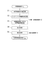
エッジ強調・ノイズ抑制処理の処理手順は、図2に示すとおりである。
まず、分解・変換処理部12において、原画像信号Sinを多重解像度変換することにより複数の空間周波数(以下、単に周波数とする)帯域の非鮮鋭画像信号を得て(ステップS1)、取得された複数の周波数帯域の非鮮鋭画像信号のうち何れかの非鮮鋭画像信号に基づいて原画像信号Sinにおけるエッジ情報及びノイズ情報を取得し(ステップS2)、取得したエッジ情報及び/又はノイズ情報に基づいて、原画像信号Sinと各周波数帯域における非鮮鋭画像信号に画素値変換処理(変換処理)を施し(ステップS3)、隣合う周波数帯域の非鮮鋭画像信号との差分(原画像信号Sinについては最高周波数帯域の非鮮鋭画像信号との差分)をとるとともに、その差分信号に所定の調整係数を掛けて差分画像信号を取得する(ステップS4)。また、復元処理部13において、この差分画像信号を原画像信号Sinに加算することにより、エッジ強調・ノイズ抑制された処理済み画像信号Soutを得る(ステップS5)。
The processing procedure of edge enhancement / noise suppression processing is as shown in FIG.
First, the decomposition /
図3は、分解・変換処理部12(12A)の構成の一例を示すブロック図である。なお、本実施の形態においては、画像入力部11を介して入力された画像(原画像信号Sin)をラプラシアンピラミッド法により多重解像変換して互いに異なる複数の周波数帯域の画像信号成分に分解するものとする。このラプラシアンピラミッド法によれば迅速な処理が可能となるが、ウェーブレット変換等、他の手法を用いることも可能である。
FIG. 3 is a block diagram illustrating an example of the configuration of the decomposition / conversion processing unit 12 (12A). In the present embodiment, the image (original image signal Sin) input via the
〔多重解像度分解処理〕
図3に示すように、入力された画像(原画像)を表すディジタルの原画像信号Sinが分解・変換処理部12に入力されると、まず、ローパスフィルタを構成するフィルタリング手段121によりフィルタリングされる。
[Multi-resolution decomposition processing]
As shown in FIG. 3, when a digital original image signal Sin representing an input image (original image) is input to the decomposition /
このようなローパスフィルタによりフィルタリングされた原画像信号Sinは1画素おきにサンプリング(ダウンサンプリング)されることで、非鮮鋭画像信号g1が生成される。この非鮮鋭画像信号g1は、原画像の1/4の大きさになっている。 The original image signal Sin filtered by such a low-pass filter is sampled (down-sampled) every other pixel, thereby generating a non-sharp image signal g1. The unsharp image signal g1 has a size that is ¼ that of the original image.
ついで、補間手段122において、この非鮮鋭画像信号g1のサンプリングされた間隔に値が0の画素が補間される。この補間は、非鮮鋭画像信号g1の列毎および1行ごとに値が0の行および列を挿入することにより行う。なお、このように補間された非鮮鋭画像信号は、1画素おきに値が0の画素が挿入されているため、信号値の変化が滑らかではない状態になっている。そして、このような補間が行われた後に、補間手段122に含まれるローパスフィルタにおいて、再度フィルタリングを施し、非鮮鋭画像信号g1′を得る。この非鮮鋭画像信号g1′は、前記した補間直後の非鮮鋭画像信号に比べると信号値の変化が滑らかな状態になっている。
Next, the
この非鮮鋭画像信号g1′は、画像を1/4にした後に1画素おきに0の補間とフィルタリングとをすることにより、原画像信号と同じ大きさとなり、また、原画像信号の空間周波数の半分より高い周波数が消えた状態になっている。
This non-sharp image signal g1 'is made the same size as the original image signal by performing interpolation and filtering of 0 every other pixel after making the
さらに、前述した非鮮鋭画像信号g1が、フィルタリング手段121によってフィルタリング処理される。これにより非鮮鋭画像信号g1は、さらに1画素おきにサンプリングされて1/4(もとの1/16)の非鮮鋭画像信号g2に変換される。そして、この非鮮鋭画像信号g2に対し、補間手段122によって同様な処理が施されて非鮮鋭画像信号g2′が生成される。
Further, the above-described unsharp
このような処理を順次繰り返すことで、非鮮鋭画像信号gk (ここで、k=1〜L(Lは1以上の整数、以下同じ))、非鮮鋭画像信号gk′を得ることができる。非鮮鋭画像信号g1′、g2′、g3′、・・・は、周波数特性の異なる複数の周波数帯域(解像度)の非鮮鋭画像信号となっている。 By sequentially repeating such processing, the unsharp image signal gk (where k = 1 to L (L is an integer of 1 or more, the same shall apply hereinafter)) and the unsharp image signal gk ′ can be obtained. The unsharp image signals g1 ′, g2 ′, g3 ′,... Are unsharp image signals in a plurality of frequency bands (resolutions) having different frequency characteristics.
〔エッジ・ノイズ情報取得処理〕
多重解像度分解処理により複数の周波数帯域の非鮮鋭画像信号gk′(ここで、k=1〜L)、が得られると、エッジ・ノイズ情報取得処理が行われる。
[Edge / noise information acquisition processing]
When a non-sharp image signal gk ′ (here, k = 1 to L) in a plurality of frequency bands is obtained by the multiresolution decomposition process, an edge noise information acquisition process is performed.
(エッジ情報の取得)
エッジ情報の取得は、複数の周波数帯域の非鮮鋭画像信号gk′のうち、何れかの基準とする第n周波数帯域の非鮮鋭画像信号gn′において行われる。図3においては、第2周波数帯域においてエッジ情報を取得する場合を例示している。
(Obtaining edge information)
The acquisition of the edge information is performed on the non-sharp image signal gn ′ in the nth frequency band as a reference among the non-sharp image signals gk ′ in a plurality of frequency bands. FIG. 3 illustrates a case where edge information is acquired in the second frequency band.
エッジ情報の取得帯域である第n周波数帯域は、画素サイズ0.5mm〜1.0mmピッチ程度の最高周波数帯域でない周波数帯域が好ましく、例えば、画素サイズ0.175ピッチの画像でダウンサンプリング率が1/2の場合、第3周波数帯域がもっとも好ましい。これは、30step/1〜2mm程度のエッジ信号にGaussianノイズを付加した擬似微小エッジ像に対して0.5mm〜1.0mmピッチの解像度でノイズ・コントラスト比が最も高くなり、エッジが認識しやすいためである。エッジ情報には、エッジ成分情報及びエッジ方向情報が含まれる。 The nth frequency band that is the edge information acquisition band is preferably a frequency band that is not the highest frequency band with a pixel size of about 0.5 mm to 1.0 mm pitch, for example, when the downsampling rate is 1/2 for an image with a pixel size of 0.175 pitch The third frequency band is most preferable. This is because the noise / contrast ratio is the highest at a resolution of 0.5mm to 1.0mm and the edge is easy to recognize with respect to the pseudo minute edge image in which Gaussian noise is added to the edge signal of about 30step / 1 ~ 2mm. is there. The edge information includes edge component information and edge direction information.
・エッジ成分情報取得処理
以下、図3、4を参照して、エッジ成分情報取得処理(図3の符号126)について説明する。
まず、非鮮鋭画像信号gn-1′と非鮮鋭画像信号gn′の差分画像信号Mnが求められる。この差分画像信号Mnに図4に示すエッジ成分情報取得処理(図3の符号126)を施すことにより、エッジ成分情報Evが取得される。
Edge Component Information Acquisition Processing Hereinafter, edge component information acquisition processing (
First, a difference image signal Mn between the unsharp image signal gn-1 'and the unsharp image signal gn' is obtained. The edge component information Ev is acquired by applying the edge component information acquisition process (reference numeral 126 in FIG. 3) shown in FIG. 4 to the difference image signal Mn.
まず、差分画像信号Mnに注目画素が設定される(ステップS11)。次いで、当該注目画素の信号値が予め定められた閾値Bh(Bhは正の信号値)以上であるか否かが判断され、閾値Bh以上であると判断された場合(ステップS12;YES)、当該注目画素が正のエッジ成分であると判別される(ステップS13)。閾値Bh以上ではない場合(ステップS12;NO)、当該注目画素の信号値が予め定められた閾値Bl(Blは負の信号値)以下であるか否かが判断され、閾値Bl以下であると判断された場合(ステップS14;YES)、当該注目画素が負のエッジ成分であると判別される(ステップS15)。 First, the target pixel is set in the difference image signal Mn (step S11). Next, it is determined whether or not the signal value of the target pixel is greater than or equal to a predetermined threshold Bh (Bh is a positive signal value), and if it is determined that the signal value is greater than or equal to the threshold Bh (step S12; YES), It is determined that the target pixel is a positive edge component (step S13). If it is not equal to or greater than the threshold value Bh (step S12; NO), it is determined whether or not the signal value of the pixel of interest is equal to or less than a predetermined threshold value Bl (Bl is a negative signal value). If it is determined (step S14; YES), it is determined that the target pixel is a negative edge component (step S15).
一方、当該注目画素の信号値が予め定められた閾値Bh以上でも閾値Bl以下でもない場合(ステップS14;NO)、当該注目画素が正・負のエッジ成分の画素に共に隣接しているか否かが判断され、隣接している場合(ステップS16;YES)、当該注目画素がエッジ変局点であると判断される(ステップS17)。エッジ変局点とは、エッジ成分の正負の変わり目となる信号値0付近の点であり、エッジの基準となる点である。
On the other hand, if the signal value of the pixel of interest is not greater than or equal to the predetermined threshold value Bh or less than the threshold value Bl (step S14; NO), whether or not the pixel of interest is adjacent to both positive and negative edge component pixels. Is determined to be adjacent (step S16; YES), it is determined that the pixel of interest is an edge inflection point (step S17). The edge inflection point is a point in the vicinity of a
一方、注目画素が正・負のエッジ成分の画素に共に隣接していないと判断された場合(ステップS16;NO)、当該注目画素が非エッジ成分であると判断される(ステップS18)。 On the other hand, when it is determined that the pixel of interest is not adjacent to the pixels of the positive and negative edge components (step S16; NO), it is determined that the pixel of interest is a non-edge component (step S18).
当該注目画素の成分が判別されると、判別結果(正のエッジ、負のエッジ、エッジ変局点、非エッジの何れか)を示す情報と画素位置とが対応付けて図示しないメモリに記憶される(ステップS19)。上述のステップS11〜S19が繰り返し実行され、全ての画素についての成分の判別が終了すると(ステップS20;YES)、本処理は終了する。 When the component of the target pixel is determined, information indicating the determination result (positive edge, negative edge, edge inflection point, or non-edge) and the pixel position are associated with each other and stored in a memory (not shown). (Step S19). When the above-described steps S11 to S19 are repeatedly executed and the determination of the components for all the pixels is completed (step S20; YES), this process ends.
図5(a)は、差分画像信号Mnの或る一列分の画像信号を模式的に示す図である。図5(b)は、図5(a)の差分画像信号Mnに上記エッジ成分情報取得処理を施した場合のエッジ成分及び非エッジ成分の分類を模式的に示す図である。上記処理により正のエッジ、負のエッジ、エッジ変局点と判断された画素がエッジ成分として抽出される。 FIG. 5A is a diagram schematically showing an image signal for a certain column of the difference image signal Mn. FIG. 5B is a diagram schematically illustrating the classification of edge components and non-edge components when the edge component information acquisition process is performed on the difference image signal Mn in FIG. Pixels determined as positive edges, negative edges, and edge inflection points by the above processing are extracted as edge components.
・ エッジ方向情報取得処理(図3の符号127)
エッジ方向情報Edは、非鮮鋭画像信号gn′にソベル(Sobel)フィルタ、プレヴィット(Prewitt)フィルタ等をかけることにより取得される。
Edge direction information acquisition process (reference numeral 127 in FIG. 3)
The edge direction information Ed is obtained by applying a Sobel filter, a Prewitt filter or the like to the unsharp image signal gn ′.
(ノイズ情報の取得)
・ノイズ情報取得処理
ノイズ情報Nsは、例えば、最高周波数帯域(第1周波数帯域)における差分画像信号M1及び中間周波数帯域(例えば、第n周波数帯域とする)における差分画像信号Mnでの局所的な分散値、エントロピー値情報及びその画素位置情報から取得することができる。
画像のエントロピー値Seは、ある画素が画素値z を取る確率 P(z) とその画像の階調数Z を用いて下記の式(数1)により求めることができる(Wiley-Interscience 社刊「Digital Image Processing 3rd Edition」参照)。

Noise information acquisition processing The noise information Ns is, for example, local in the difference image signal M1 in the highest frequency band (first frequency band) and the difference image signal Mn in the intermediate frequency band (for example, the nth frequency band). It can be obtained from the variance value, the entropy value information and the pixel position information.
The entropy value Se of an image can be obtained by the following equation (Equation 1) using the probability P (z) of a pixel taking the pixel value z and the number of gradations Z of the image (“Wiley-Interscience” published “ Digital Image Processing 3rd Edition ").
〔非鮮鋭画像信号に対する画素値変換処理〕
エッジ情報・ノイズ情報が取得されると、取得されたエッジ情報及び/又は情報に基づいて、原画像信号Sin及び各周波数帯域の非鮮鋭画像信号gk(k=1〜k=L-1)に画素値変換処理(図3の符号123)が施される。
画素値変換処理は、エッジ平滑化処理、ノイズ平滑化処理の少なくとも一つを施すものである。また、エッジ平滑化処理、ノイズ平滑化処理の少なくとも一つを施した後、濃度依存補正処理を施すとより好ましい。
[Pixel value conversion processing for unsharp image signals]
When the edge information / noise information is acquired, based on the acquired edge information and / or information, the original image signal Sin and the unsharp image signal gk (k = 1 to k = L-1) of each frequency band are obtained. Pixel value conversion processing (
The pixel value conversion process performs at least one of an edge smoothing process and a noise smoothing process. It is more preferable to perform density-dependent correction processing after performing at least one of edge smoothing processing and noise smoothing processing.
平滑化に用いるフィルタは多重解像度変換処理で用いるダウンサンプリングフィルタかそれに近い周波数応答のローパスフィルタであることが望ましい。図6は、多重解像度分解のダウンサンプリングをバイノミアルフィルタリング(binomial Filtering)を8回行うラプラシアンピラミッド法で行った場合に用いる平滑化フィルタ係数(5tap)の一例である。例えば、タップ数が5tapである場合、フィルタ係数F(x)は、以下の関数(数2)(数3)で表されることが望ましい。
以下、エッジ平滑化処理、ノイズ平滑化処理、濃度依存補正処理についてそれぞれ説明する。 Hereinafter, edge smoothing processing, noise smoothing processing, and density-dependent correction processing will be described.
・エッジ平滑化処理
エッジ平滑化処理においては、原画像信号Sin及び各周波数帯域の非鮮鋭画像信号gk(k=1〜k=L-1)のそれぞれの、上述のエッジ情報取得処理においてエッジ成分と判別された画素について、平滑化フィルタ(例えば、図6(b)参照)によりエッジ勾配方向のみに一次元的な平滑化処理を施す。これにより、主にノイズ成分と1レベル下の周波数帯域の周波数成分からなる画像信号が得られる。
Edge smoothing process In the edge smoothing process, an edge component is obtained in the above-described edge information acquisition process of each of the original image signal Sin and the unsharp image signal gk (k = 1 to k = L-1) in each frequency band. A one-dimensional smoothing process is performed only on the edge gradient direction by a smoothing filter (see, for example, FIG. 6B) for the pixels determined to be. As a result, an image signal mainly including a noise component and a frequency component in a frequency band one level below is obtained.
・ノイズ平滑化処理
ノイズ平滑化処理においては、原画像信号Sin及び各周波数帯域の非鮮鋭画像信号gk(k=1〜k=L-1)のそれぞれの、上述のエッジ情報取得処理において非エッジ成分と判別された画素について、平滑化フィルタ(例えば、図6(a)参照)により二次元的な平滑化処理を行い、エッジ成分と判別された画素については、平滑化フィルタ(例えば、図6(b)参照)によりエッジ勾配方向以外の方向又はエッジ勾配方向と垂直な方向のみに一次元的な平滑化処理を施す。これにより、主にエッジ成分と1レベル下の周波数帯域の周波数成分からなる画像信号のみが得られる。
Noise smoothing process In the noise smoothing process, each of the original image signal Sin and each non-sharp image signal gk (k = 1 to k = L-1) in each frequency band is not edged in the above-described edge information acquisition process. A pixel determined to be a component is subjected to a two-dimensional smoothing process using a smoothing filter (for example, see FIG. 6A), and a pixel determined to be an edge component is subjected to a smoothing filter (for example, FIG. 6). As shown in (b), a one-dimensional smoothing process is performed only in a direction other than the edge gradient direction or in a direction perpendicular to the edge gradient direction. As a result, only an image signal composed mainly of an edge component and a frequency component in a frequency band one level below is obtained.
・濃度依存補正処理
濃度依存補正処理とは、エッジ強調・ノイズ抑制処理において発生するアーティファクト、ノイズの発生を抑制するために、図7に示す補正関数により画像信号の濃度(画像信号値)及びコントラスト(濃度依存補正処理前の隣合う周波数帯域の非鮮鋭画像信号同士の差分画像信号(原画像信号Sinについては最高周波数帯域の非鮮鋭画像信号g1との差分画像信号))に応じて得られる補正成分値を、ノイズ平滑化処理、及び/又はエッジ平滑化処理後の画像信号値から減算する処理である。図7に示す補正関数は、各周波数帯域ごとに定義されている。
Density-dependent correction processing Density-dependent correction processing refers to image signal density (image signal value) and contrast using a correction function shown in FIG. 7 in order to suppress artifacts and noise generated in edge enhancement / noise suppression processing. Correction obtained in accordance with (difference image signal between non-sharp image signals in adjacent frequency bands before density-dependent correction processing (for original image signal Sin, difference image signal from unsharp image signal g1 in the highest frequency band)) This is a process of subtracting the component value from the image signal value after the noise smoothing process and / or the edge smoothing process. The correction function shown in FIG. 7 is defined for each frequency band.
エッジ強調・ノイズ抑制処理では、処理を強くかけるとアーティファクトの発生やノイズの増幅により逆に画質が損なわれてしまうことがある。エッジ強調処理ではノイズ成分の増幅が問題となり、低濃度部で目立ちやすい。また、アーティファクト、ノイズは、低濃度部で目立ちやすい。 In the edge enhancement / noise suppression processing, if the processing is applied strongly, the image quality may be adversely affected due to artifacts or noise amplification. In edge emphasis processing, amplification of noise components becomes a problem, and it tends to stand out in low density areas. Artifacts and noise are conspicuous in the low density portion.
ここで、エッジ強調・ノイズ抑制処理では、上述したように、原画像信号Sinと各周波数帯域における非鮮鋭画像信号に画素値変換処理を施して変換画像信号を生成し、その後、変換画像信号と隣合う周波数帯域の非鮮鋭画像信号との差分画像信号(原画像信号Sinの変換画像信号については最高周波数帯域の非鮮鋭画像信号g1との差分)を原画像信号Sinに加算することにより、エッジ強調・ノイズ抑制された処理済み画像Soutを得るものである。すなわち、図7でいうコントラストの値が原画像信号Sinに加算されることとなる。差分画像信号(コントラスト)は、エッジ平滑化処理を施したものであれば主にノイズ成分からなる画像信号となり、ノイズ平滑化処理を施したものであれば主にエッジ成分からなる画像信号である。この差分画像信号(コントラスト)の値が0に近くなるように図7に示す補正関数での補正量を大きくするにつれて、原画像信号Sinに加算される信号成分が小さくなる、即ち、エッジ強調・ノイズ抑制処理が弱まる。 Here, in the edge enhancement / noise suppression processing, as described above, the original image signal Sin and the unsharp image signal in each frequency band are subjected to pixel value conversion processing to generate a converted image signal, and then the converted image signal and By adding a difference image signal (a difference from the unsharp image signal g1 in the highest frequency band for the converted image signal of the original image signal Sin) to the original image signal Sin from an adjacent non-sharp image signal in the adjacent frequency band, an edge is obtained. A processed image Sout that is enhanced and noise-suppressed is obtained. That is, the contrast value shown in FIG. 7 is added to the original image signal Sin. The difference image signal (contrast) is an image signal mainly composed of a noise component if it is subjected to edge smoothing, and is an image signal mainly composed of an edge component if it is subjected to noise smoothing. . As the correction amount in the correction function shown in FIG. 7 is increased so that the value of the difference image signal (contrast) is close to 0, the signal component added to the original image signal Sin decreases, that is, edge enhancement / Noise suppression processing is weakened.
図8は、図7の補正関数のコントラストに対する応答を表した図である。図8に示すように、図7に示す補正関数は、いずれの周波数帯域においても低コントラスト部より高コントラスト部で強い補正がはたらくことがわかる。図9は、図7の補正関数の濃度に対する応答を表した図である。図9に示すように、図7に示す補正関数は、いずれの周波数帯域においても高濃度部より低濃度部で強い補正がはたらくことがわかる。
このように、濃度依存補正処理により、低濃度部でエッジ強調・ノイズ抑制処理を抑える補正を強くかけておくことにより、エッジ強調及びノイズ抑制処理において発生するアーティファクト、ノイズの発生を抑制することができる。
FIG. 8 is a diagram showing the response of the correction function of FIG. 7 to the contrast. As shown in FIG. 8, it can be seen that the correction function shown in FIG. 7 performs stronger correction in the high contrast portion than in the low contrast portion in any frequency band. FIG. 9 is a diagram showing the response to the density of the correction function of FIG. As shown in FIG. 9, it can be seen that the correction function shown in FIG. 7 performs stronger correction in the low density part than in the high density part in any frequency band.
In this way, by performing correction that suppresses edge enhancement / noise suppression processing in a low density portion by density-dependent correction processing, it is possible to suppress artifacts and noise generated in edge enhancement and noise suppression processing. it can.
〔差分処理〕
原画像信号Sin及び各周波数帯域の非鮮鋭画像信号gk(k=1〜k=L-1)に画素値変換処理が施されると、まず、図3の減算器124により、変換済みの原画像信号S′(変換画像信号)から非鮮鋭画像信号g1′の減算を行って、差分画像信号b0を得る。この減算は、変換済みの原画像信号S′と非鮮鋭画像信号g1′との対応する画素の間で実行される。
[Difference processing]
When pixel value conversion processing is performed on the original image signal Sin and the unsharp image signal gk (k = 1 to k = L−1) in each frequency band, first, the converted original image is processed by the
また、減算器124により、変換処理済みの非鮮鋭画像信号G1(変換画像信号)から非鮮鋭画像信号g2′の減算を行って、差分画像信号b1を得る。
Further, the
このような処理を順次繰り返すことで、差分画像信号bk-1(k=1〜k=L)を得る。そして、得られた差分画像信号bk-1のそれぞれに所定の調整係数であるエッジ強調・ノイズ抑制係数βkをかけ、原画像信号Sinに加算する画像信号成分を調整する。 By sequentially repeating such processing, a difference image signal bk-1 (k = 1 to k = L) is obtained. Then, the obtained difference image signal bk-1 is multiplied by an edge enhancement / noise suppression coefficient βk, which is a predetermined adjustment coefficient, to adjust the image signal component to be added to the original image signal Sin.
図10は、エッジ平滑化及び/又はノイズ平滑化処理を行った後濃度依存補正処理した非鮮鋭画像信号から一つ下の周波数帯域の非鮮鋭画像信号の減算を行った際に得られる差分信号にエッジ強調・ノイズ抑制係数βk(k=1〜k=L)をかけた時の処理応答と濃度との関係を示す図である。図10に示すように、差分画像信号bk-1(k=1〜k=L)にエッジ強調・ノイズ抑制係数βkをかけた時の処理応答は、アーティファクト、ノイズの目立ちやすい低濃度部ほど低くなり、低濃度部ほど処理の強さが抑えられる。 FIG. 10 shows a difference signal obtained when subtracting the non-sharp image signal in the next lower frequency band from the non-sharp image signal that has been subjected to edge smoothing and / or noise smoothing and then subjected to density-dependent correction processing. FIG. 6 is a diagram showing a relationship between processing response and density when an edge enhancement / noise suppression coefficient βk (k = 1 to k = L) is applied to the image. As shown in FIG. 10, the processing response when the edge enhancement / noise suppression coefficient βk is applied to the differential image signal bk-1 (k = 1 to k = L) is lower in the low density portion where artifacts and noise are conspicuous. Thus, the strength of processing is suppressed as the density is low.
〔復元処理〕
図11は、多重解像度分解処理により得られた複数の周波数帯域の非鮮鋭画像信号に画素値変換処理を施して、それぞれ1レベル下の周波数帯域の非鮮鋭画像信号を減算して得られた差分画像信号bk-1(k=1〜L)を原画像信号Sinに加算して逆変換する復元処理部13の構成の一例を示すブロック図である。なお、本実施の形態例においては、ラプラシアンピラミッド法により複数の細部画像から逆変換(復元)するものとする。このラプラシアンピラミッド法によれば迅速な処理が可能となるが、他の手法を用いることも可能である。
[Restore processing]
FIG. 11 shows a difference obtained by subjecting a non-sharp image signal of a plurality of frequency bands obtained by multi-resolution decomposition processing to pixel value conversion processing and subtracting the non-sharp image signal of a frequency band one level below. It is a block diagram which shows an example of a structure of the decompression |
まず、差分画像信号bL-1が補間手段131によって各画素の間が補間されて4倍の大きさの画像信号bL-1′とされる。次に、加算器132で、補間された画像信号bL-1′と、1段階周波数帯域の高い非鮮鋭画像信号bL-2とが対応する画素同士で加算され、加算画像信号(bL-1′+bL-2)が得られる。
First, the difference image signal bL-1 is interpolated between the pixels by the interpolation means 131 to obtain an image signal bL-1 'having a quadruple magnitude. Next, in the
次いで、この加算画像信号(bL-1′+bL-2)が、補間手段131によって各画素の間が補間されてさらに4倍の大きさの画像bL-2′とされる。つぎに、加算器132で、補間された画像bL-2′と、1段周波数帯域の高い非鮮鋭画像信号bL-3とが対応する画素同士で加算され、加算画像信号(bL-2′+bL-3)が得られる。
Next, the added image signal (bL-1 ′ + bL-2) is interpolated between the pixels by the
以上の処理を繰り返す。そしてこの処理をより高周波の差分画像信号に対して順次行い、最終的に加算器132において補間された画像信号b1′と最高解像度の差分画像信号b0とを加算したものを加算器133で原画像信号Sinと加算して処理済み画像信号Soutを得る。
The above processing is repeated. Then, this process is sequentially performed on the higher-frequency difference image signal, and finally the image signal b1 'interpolated by the
〔画像出力処理〕
以上のように、分解・変換処理され、復元処理された処理済み画像信号Soutについて、画像出力部14において可視像として印刷あるいは表示の出力がなされる。また、各種ディスク装置にディジタルデータとして記憶される。
[Image output processing]
As described above, the processed image signal Sout subjected to the decomposition / conversion processing and the restoration processing is printed or displayed as a visible image in the
以上説明したように、画像処理装置10によれば、画像信号を多重解像度分解処理して得られた基準となる周波数帯域において取得されたエッジ情報及び/又はノイズ情報に基づいて、複数の周波数帯域の非鮮鋭画像信号及び原画像信号にノイズ平滑化処理、エッジ平滑化処理の少なくとも一つを施してエッジ成分及び/又はノイズ成分を取得し、この取得したエッジ成分及び/又はノイズ成分に濃度依存補正処理を施して変換画像信号を得る。そして、得られた変換画像信号のそれぞれと隣合う周波数帯域(原画像信号に対しては最高周波数帯域)の非鮮鋭画像信号との差分画像信号を取得し、各差分画像信号に対し所定の調整係数をかけ、それぞれを原画像信号に加算して処理済み画像信号を得る。
As described above, according to the
従って、エッジ強調・ノイズ抑制処理によるノイズやアーティファクトの発生を抑制しつつ、画像信号中の構造物の輪郭などのエッジ成分の強調及び/又はノイズ成分の減弱を行うことが可能となる。 Therefore, it is possible to enhance edge components such as the outline of a structure in an image signal and / or reduce noise components while suppressing the occurrence of noise and artifacts due to edge enhancement / noise suppression processing.
<第2の実施の形態>
以下、本発明の第2の実施の形態について説明する。
第2の実施の形態においては、上述の第1の実施の形態と分解・変換処理部12における処理が異なる。
<Second Embodiment>
Hereinafter, a second embodiment of the present invention will be described.
In the second embodiment, the processing in the decomposition /
図12は、第2の実施の形態における分解・変換処理部12(12B)の構成の一例を示すブロック図である。なお、本実施の形態においては、画像入力部11を介して入力された画像(原画像信号Sin)をラプラシアンピラミッド法により多重解像変換して互いに異なる複数の周波数帯域の画像信号成分に分解するものとする。このラプラシアンピラミッド法によれば迅速な処理が可能となるが、ウェーブレット変換等、他の手法を用いることも可能である。
FIG. 12 is a block diagram illustrating an example of the configuration of the decomposition / conversion processing unit 12 (12B) according to the second embodiment. In the present embodiment, the image (original image signal Sin) input via the
〔多重解像度分解処理〕
図12に示すように、入力された画像(原画像)を表すディジタルの原画像信号Sinが分解・変換処理部12に入力されると、まず、ローパスフィルタを構成するフィルタリング手段121によりフィルタリングされる。
[Multi-resolution decomposition processing]
As shown in FIG. 12, when a digital original image signal Sin representing an input image (original image) is input to the decomposition /
このようなローパスフィルタによりフィルタリングされた原画像信号Sinは1画素おきにサンプリング(ダウンサンプリング)されることで、非鮮鋭画像信号g1が生成される。この非鮮鋭画像信号g1は、原画像の1/4の大きさになっている。 The original image signal Sin filtered by such a low-pass filter is sampled (down-sampled) every other pixel, thereby generating a non-sharp image signal g1. The unsharp image signal g1 has a size that is ¼ that of the original image.
ついで、補間手段122において、この非鮮鋭画像信号g1のサンプリングされた間隔に値が0の画素が補間される。この補間は、非鮮鋭画像信号g1の列毎および1行ごとに値が0の行および列を挿入することにより行う。なお、このように補間された非鮮鋭画像信号は、1画素おきに値が0の画素が挿入されているため、信号値の変化が滑らかではない状態になっている。そして、このような補間が行われた後に、補間手段122に含まれるローパスフィルタにおいて、再度フィルタリングを施し、非鮮鋭画像信号g1′を得る。この非鮮鋭画像信号g1′は、前記した補間直後の非鮮鋭画像信号に比べると信号値の変化が滑らかな状態になっている。
Next, the
この非鮮鋭画像信号g1′は、画像を1/4にした後に1画素おきに0の補間とフィルタリングとをすることにより、原画像信号Sinと原画像信号と同じ大きさとなり、原画像信号Sinの空間周波数の半分より高い周波数が消えた状態になっている。
This non-sharp image signal g1 'becomes the same size as the original image signal Sin and the original image signal by performing interpolation and filtering of 0 every other pixel after making the
さらに、前述した非鮮鋭画像信号g1が、フィルタリング手段121によってフィルタリング処理される。これにより非鮮鋭画像信号g1は、さらに1画素おきにサンプリングされて1/4(もとの1/16)の非鮮鋭画像信号g2に変換される。そして、この非鮮鋭画像信号g2に対し、補間手段122によって同様な処理が施されて非鮮鋭画像信号g2′が生成される。
Further, the above-described unsharp
このような処理を順次繰り返すことで、非鮮鋭画像信号gk (ここで、k=1〜L)、非鮮鋭画像信号gk′を得ることができる。非鮮鋭画像信号g1′、g2′、g3′、・・・は、周波数特性の異なる複数の周波数帯域の非鮮鋭画像信号となっている。 By sequentially repeating such processing, the unsharp image signal gk (here, k = 1 to L) and the unsharp image signal gk ′ can be obtained. The unsharp image signals g1 ', g2', g3 ', ... are unsharp image signals in a plurality of frequency bands having different frequency characteristics.
〔エッジ・ノイズ情報取得処理〕
多重解像度分解処理により複数の周波数帯域の非鮮鋭画像信号gk′(ここで、k=1〜L)、が得られると、複数の周波数帯域の非鮮鋭画像信号gk′のうち、何れかの基準とする第n周波数帯域の非鮮鋭画像信号gn′においてエッジ・ノイズ情報の取得処理が行われる。エッジ/ノイズ情報取得部の機能構成は、図12においては図示しないが、第1の実施の形態で説明したエッジ情報・ノイズ情報取得処理と同様の処理によりエッジ成分情報、エッジ方向情報、ノイズ情報を得る。
[Edge / noise information acquisition processing]
When the non-sharp image signal gk ′ (where k = 1 to L) in a plurality of frequency bands is obtained by the multi-resolution decomposition process, any one of the non-sharp image signals gk ′ in the plurality of frequency bands is obtained. Edge noise information acquisition processing is performed on the unsharp image signal gn ′ in the nth frequency band. Although the functional configuration of the edge / noise information acquisition unit is not shown in FIG. 12, edge component information, edge direction information, and noise information are obtained by processing similar to the edge information / noise information acquisition processing described in the first embodiment. Get.
エッジ成分情報、エッジ方向情報、ノイズ情報が取得されると、取得された情報に基づいて、原画像信号Sin及び各周波数帯域の非鮮鋭画像信号gk(k=1〜k=L-1)に画素値変換処理が施される。第2の実施の形態においては、原画像信号Sin及び各周波数帯域の非鮮鋭画像信号gk(k=1〜k=L-1)に対して、エッジ平滑化処理及び濃度依存補正処理P1、ノイズ平滑化処理及び濃度依存補正処理P2がそれぞれ別個に施される。 When the edge component information, edge direction information, and noise information are acquired, based on the acquired information, the original image signal Sin and the unsharp image signal gk (k = 1 to k = L-1) in each frequency band are obtained. Pixel value conversion processing is performed. In the second embodiment, edge smoothing processing, density-dependent correction processing P1, noise, and the like are performed on the original image signal Sin and the unsharp image signal gk (k = 1 to k = L-1) in each frequency band. Smoothing processing and density-dependent correction processing P2 are performed separately.
エッジ平滑化処理、ノイズ平滑化処理は、上述の第1の実施の形態で説明したのと同様の処理により行われる。エッジ平滑化処理では、主にノイズ成分と1レベル下の周波数帯域の周波数成分からなる画像信号が得られる。ノイズ平滑化処理では、主にエッジ成分と1レベル下の周波数帯域の周波数成分からなる画像信号のみが得られる。 The edge smoothing process and the noise smoothing process are performed by the same process as described in the first embodiment. In the edge smoothing process, an image signal mainly including a noise component and a frequency component in a frequency band one level below is obtained. In the noise smoothing process, only an image signal mainly composed of an edge component and a frequency component in a frequency band one level below is obtained.
エッジ平滑化処理、ノイズ平滑化処理を原画像信号Sin及び各周波数帯域の非鮮鋭画像信号gk(k=1〜k=L-1)のそれぞれに別個にかけてエッジ成分とノイズ成分を別々に抽出することで、エッジ成分、ノイズ成分のそれぞれに個別に濃度依存補正処理等を施すことが可能となる。 Edge smoothing processing and noise smoothing processing are separately performed on the original image signal Sin and the non-sharp image signal gk (k = 1 to k = L-1) of each frequency band, and edge components and noise components are extracted separately. As a result, it is possible to individually perform density-dependent correction processing or the like on each of the edge component and the noise component.
濃度依存補正処理は、上述の第1の実施の形態で説明したのと略同様であるが、ノイズ平滑化処理後の主にエッジ成分からなる非鮮鋭画像信号に濃度補正依存処理を施す際に使用する補正関数と、ノイズ平滑化処理後の主にノイズ成分からなる非鮮鋭画像信号に濃度依存補正処理を施す際に使用する補正関数をそれぞれ用意しておくことで、画像信号の成分に応じて異なる補正をかけることができる。 The density-dependent correction process is substantially the same as that described in the first embodiment, but when the density correction-dependent process is performed on a non-sharp image signal mainly composed of edge components after the noise smoothing process. Prepare a correction function to be used and a correction function to be used when density-dependent correction processing is applied to a non-sharp image signal mainly composed of noise components after noise smoothing. Different corrections can be made.
図13は、ノイズ平滑化処理後の主にエッジ成分からなる非鮮鋭画像信号に使用する補正関数の濃度に対する応答を表した図である。図13に示すように、高濃度部より低濃度部で強い補正がかかっており、エッジ強調処理が高濃度部で強くかかることがわかる。
図14は、エッジ平滑化処理後の主にノイズ成分からなる非鮮鋭画像信号に使用する補正関数の濃度に対する応答を表した図である。図14に示すように、低濃度部より高濃度部で強い補正がかかっており、ノイズ抑制処理が低濃度部で強くかかることがわかる。
FIG. 13 is a diagram showing the response to the density of the correction function used for the non-sharp image signal mainly composed of edge components after the noise smoothing process. As shown in FIG. 13, it can be seen that stronger correction is applied in the low density part than in the high density part, and the edge enhancement processing is applied more strongly in the high density part.
FIG. 14 is a diagram showing the response to the density of the correction function used for the non-sharp image signal mainly composed of noise components after the edge smoothing process. As shown in FIG. 14, it can be seen that stronger correction is applied in the high density part than in the low density part, and that the noise suppression process is applied more strongly in the low density part.
このように、ノイズの目立ちやすい低濃度部では、ノイズ抑制処理を強めにかけエッジ強調処理を弱めるように補正をかけることにより、ノイズを目立ちにくくすることができる。一方、ノイズの目立ちにくい高濃度部ではノイズ抑制処理を弱め、エッジ強調処理を強める補正を行うことにより、ノイズ抑制処理によるノイズ、アーティファクトの発生を弱めることができる。
〔差分処理〕
原画像信号Sin及び各周波数帯域の非鮮鋭画像信号gk(k=1〜k=L-1)にエッジ平滑化処理及び濃度依存補正処理が施されると、まず、図12に示す減算器128において、エッジ平滑化処理及び濃度依存補正処理済みの原画像信号SN′(第1の変換画像信号)から非鮮鋭画像信号g1′の減算を行う。この減算は、原画像信号SN′と非鮮鋭画像信号g1′との対応する画素の間で実行される。そして、減算により得られた主にノイズ成分からなる差分信号に所定のノイズ調整係数(ノイズコントロール係数)βN1(0>βNk>−1)が掛けられ、ノイズ成分が減弱調整された差分画像信号N0が得られる。
As described above, in the low density portion where noise is conspicuous, the noise can be made inconspicuous by performing correction so as to weaken the edge emphasis processing by applying the noise suppression processing stronger. On the other hand, noise and artifacts due to the noise suppression process can be reduced by performing a correction that weakens the noise suppression process and strengthens the edge enhancement process in the high density portion where the noise is not noticeable.
[Difference processing]
When edge smoothing processing and density-dependent correction processing are performed on the original image signal Sin and the unsharp image signal gk (k = 1 to k = L-1) in each frequency band, first, a
同様に、減算器129により、ノイズ平滑化処理及び濃度依存補正処理済みの原画像信号SE′(第2の変換画像信号)から非鮮鋭画像信号g1′の減算を行う。この減算は、ノイズ平滑化処理及び濃度依存補正処理済みの原画像信号SE′と非鮮鋭画像信号g1′との対応する画素の間で実行される。そして、減算により得られた主にエッジ成分からなる差分信号に、所定のエッジ調整係数(エッジコントロール係数)βE1(βEk>1)が掛けられ、エッジ成分が強調調整された差分画像信号E0が得られる。この差分画像信号N0と差分画像画像信号E0を加算器130により加算することにより、差分画像信号B0が得られる。
Similarly, the
また、減算器128により、エッジ平滑化処理及び濃度依存補正処理済みの非鮮鋭画像信号gN1′(第1の変換画像信号)から非鮮鋭画像信号g2′の減算を行う。この減算は、非鮮鋭画像信号gN1′と非鮮鋭画像信号g2′との対応する画素の間で実行される。そして、減算により得られた主にノイズ成分からなる差分信号に、所定のノイズコントロール係数βN2が掛けられ、ノイズ成分が減弱調整された差分画像信号N1が得られる。
Further, the
同様に、減算器129により、ノイズ平滑化処理及び濃度依存補正処理済みの非鮮鋭画像信号gE1′(第2の変換画像信号)から非鮮鋭画像信号g2′の減算を行う。この減算は、非鮮鋭画像信号gE1′と非鮮鋭画像信号g2′との対応する画素の間で実行される。そして、減算により得られた主にエッジ成分からなる差分信号に、所定のエッジコントロール係数βE1が掛けられ、エッジ成分が強調調整された差分画像信号E1が得られる。この差分画像信号N1と差分画像信号E1を加算器130により加算することにより、差分画像信号B1が得られる。
Similarly, the
このような処理を順次繰り返すことで、差分画像信号Bk-1(k=1〜k=L)を得る。得られた差分画像信号Bk-1は、図示しない画像メモリに格納される。 By sequentially repeating such processing, a difference image signal Bk-1 (k = 1 to k = L) is obtained. The obtained difference image signal Bk-1 is stored in an image memory (not shown).
図15は、ノイズ平滑化処理及び濃度依存補正処理済みの非鮮鋭画像信号から一つ下の周波数帯域の非鮮鋭画像信号の減算を行った際に得られる主にエッジ成分からなる差分信号にエッジコントロール係数βEkをかけた時の処理応答(図15のエッジ成分処理応答)と濃度との関係を示す図、及びエッジ平滑化処理及び濃度依存補正処理済みの非鮮鋭画像信号から一つ下の周波数帯域の非鮮鋭画像信号の減算を行った際に得られる主にノイズ成分からなる差分信号にノイズコントロールβNkをかけたときの処理応答(図15のノイズ成分処理応答)と濃度との関係を示す図である。図15に示すように、濃度依存補正処理をノイズ成分、エッジ成分に個別に施した結果、低濃度部ではノイズ抑制処理が強めにかかり、エッジ強調処理が抑えられる。これにより、低濃度部でノイズを目立ちにくくすることができる。また、ノイズの目立ちにくい高濃度部では、ノイズ抑制処理が弱めにかかり、エッジ強調処理が強めにかかる。これにより、高濃度部ではノイズ抑制処理を弱めてノイズ処理により生じるアーティファクトを抑えつつ、エッジ強調を強くかけることが可能となる。 FIG. 15 shows a difference signal mainly composed of edge components obtained by subtracting a non-sharp image signal in the next lower frequency band from a non-sharp image signal that has been subjected to noise smoothing processing and density-dependent correction processing. The figure which shows the relationship between the processing response (edge component processing response in FIG. 15) and the density when the control coefficient βEk is applied, and the frequency one level lower than the non-sharp image signal which has been subjected to the edge smoothing process and the density dependent correction process 15 shows the relationship between the processing response (noise component processing response in FIG. 15) and density when the noise control βNk is applied to the difference signal mainly composed of noise components obtained when subtracting the non-sharp image signal in the band. FIG. As shown in FIG. 15, as a result of performing the density-dependent correction processing separately for the noise component and the edge component, the noise suppression processing is strengthened in the low density portion, and the edge enhancement processing is suppressed. Thereby, noise can be made inconspicuous in the low density portion. In a high density portion where noise is not noticeable, the noise suppression processing is weakened and the edge enhancement processing is strong. Thereby, in the high density part, it is possible to weaken the noise suppression process and suppress the artifacts caused by the noise process, and to apply the edge enhancement strongly.
エッジ成分はどの周波数帯域でも存在するが、ノイズ成分は主に高周波成分であるので、低周波帯域からノイズ抑制処理を強くかけると画像がぼけてしまう。そこで、エッジ平滑化処理により取得された画像信号に掛けるノイズコントロール係数βNk、ノイズ平滑化処理により取得された画像信号に掛けるエッジコントロール係数βEkをそれぞれ個別に設定し、エッジコントロール係数βEkを低周波帯域から高周波帯域のそれぞれのエッジ成分にかけてエッジ強調を低周波帯域から高周波帯域にかけて行い、ノイズコントロール係数βNkを高周波数帯域のみのノイズ成分にかけて高周波数帯域のみにノイズ抑制を行うことで、図16に示すようにエッジ成分及びノイズ成分に対して異なった周波数応答を得ることができ、低周波数帯でのノイズ抑制処理を抑えて画像のぼけを抑制することが可能となる。 Although the edge component exists in any frequency band, the noise component is mainly a high-frequency component, so that if the noise suppression process is strongly applied from the low-frequency band, the image is blurred. Therefore, the noise control coefficient βNk to be applied to the image signal acquired by the edge smoothing process and the edge control coefficient βEk to be applied to the image signal acquired by the noise smoothing process are individually set, and the edge control coefficient βEk is set to the low frequency band. 16 is performed by performing edge enhancement from the low frequency band to the high frequency band from the low frequency band to the high frequency band and performing noise suppression only on the high frequency band by applying the noise control coefficient βNk to the noise component of only the high frequency band. Thus, different frequency responses can be obtained for the edge component and the noise component, and it is possible to suppress blurring of the image by suppressing noise suppression processing in the low frequency band.
〔復元処理〕
復元処理部13においては、分解・変換処理部12で取得された差分画像信号Bk-1(k=1〜k=L)を原画像信号Sinに加算して逆変換し、画像信号Soutを出力する。復元処理部13の構成は、入力信号が異なる他は、図11で説明したのと同様であるので説明を省略する。
[Restore processing]
In the
復元処理された画像信号Soutは、画像出力部14において可視像として印刷あるいは表示の出力がなされる。また、各種ディスク装置にディジタルデータとして記憶される。
The restored image signal Sout is printed or displayed as a visible image in the
以上説明したように、画像処理装置10によれば、画像信号を多重解像度分解処理して得られた基準となる周波数帯域において取得されたエッジ情報及び/又はノイズ情報に基づいて、複数の周波数帯域の非鮮鋭画像信号及び原画像信号にノイズ平滑化処理及び濃度依存補正処理を施して、主にエッジ成分からなる第1の変換画像信号を取得し、この第1の変換画像信号のそれぞれと隣合う周波数帯域(原画像信号に対しては最高周波数帯域)の非鮮鋭画像信号との差分画像信号を取得し、各差分画像信号に対しエッジコントロール係数を掛けてエッジ成分の強調を行う。また、画像信号を多重解像度分解処理して得られた基準となる周波数帯域において取得されたエッジ情報及び/又はノイズ情報に基づいて、複数の周波数帯域の非鮮鋭画像信号及び原画像信号にエッジ平滑化処理及び濃度依存補正処理を施して、主にノイズ成分からなる第2の変換画像信号を取得し、この第2の変換画像信号のそれぞれと隣合う周波数帯域(原画像信号に対しては最高周波数帯域)の非鮮鋭画像信号との差分画像信号を取得し、各差分画像信号に対しノイズコントロール係数を掛けてノイズ成分の抑制を行う。そして、得られたエッジ強調差分画像信号及びノイズ抑制差分画像信号を原画像信号に加算して処理済み画像を得る。
As described above, according to the
従って、エッジ強調・ノイズ抑制処理によるノイズやアーティファクトの発生を抑制しつつ、画像信号中の構造物の輪郭などのエッジ成分の強調、ノイズ成分の減弱を行うことが可能となる。 Therefore, it is possible to enhance edge components such as contours of structures in the image signal and attenuate noise components while suppressing the generation of noise and artifacts due to edge enhancement / noise suppression processing.
なお、以上の実施の形態例においては、ラプラシアンピラミッド法を用いて多重解像度空間への変換と多重解像度空間からの逆変換を行うようにしていた。この変換と逆変換とを、ウェーブレット変換により行うことで、任意の方向(縦方向,横方向,斜め方向)についての強調処理を行うことが可能になる。 In the above embodiment, the Laplacian pyramid method is used to perform the conversion to the multi-resolution space and the inverse conversion from the multi-resolution space. By performing this transformation and inverse transformation by wavelet transformation, it is possible to perform enhancement processing in any direction (vertical direction, horizontal direction, diagonal direction).
また、上記第1及び第2の実施の形態においては、全ての周波数帯域において差分画像信号を取得し、これを原画像信号に加算することとしたが、これに限定されず、少なくとも一つの周波数帯域において差分画像信号を得てエッジ強調及び/又はノイズ抑制処理を行うことで、エッジ強調、ノイズ抑制を行うことができる。 In the first and second embodiments, the difference image signal is acquired in all frequency bands and added to the original image signal. However, the present invention is not limited to this, and at least one frequency is used. Edge enhancement and noise suppression can be performed by obtaining a differential image signal in the band and performing edge enhancement and / or noise suppression processing.
また、以上の実施の形態例の画像処理方法および画像処理装置は、放射線画像、MRIによる画像、CTによる画像、その他の各種画像において強調処理を行うに適している。 In addition, the image processing method and the image processing apparatus according to the above-described embodiments are suitable for performing enhancement processing on a radiation image, an MRI image, an CT image, and other various images.
その他、画像処理装置10を構成する各装置の細部構成及び細部動作に関しても、本発明の趣旨を逸脱することのない範囲で適宜変更可能である。
In addition, the detailed configuration and detailed operation of each device constituting the
10 画像処理装置
11 画像入力部
12 分解・変換処理部
13 復元処理部
14 画像出力部
DESCRIPTION OF
Claims (14)
前記変換処理工程は、
前記入力画像信号のエッジ情報及び/又はノイズ情報を取得する情報取得工程と、
前記取得したエッジ情報及び/又はノイズ情報に基づいて、前記入力画像信号及び/又は前記複数の周波数帯域の非鮮鋭画像信号の少なくとも一つにエッジ平滑化処理又はノイズ平滑化処理のうちの少なくとも一つの処理を施した後、濃度依存補正処理を施して前記変換画像信号を得る工程と、
を含むことを特徴とする画像処理方法。 A resolution processing step of obtaining multi-resolution conversion of the input image signal to obtain non-sharp image signals of a plurality of different frequency bands; and at least one of the input image signal and / or the non-sharp image signals of the plurality of frequency bands A conversion processing step for obtaining a difference image signal by taking a difference between the converted image signal obtained by performing the conversion process and an image signal in the frequency band adjacent to the converted image signal or an image signal in the highest frequency band; and the difference image signal And a restoration processing step of obtaining a processed image by adding to the input image signal,
The conversion process step includes
An information acquisition step of acquiring edge information and / or noise information of the input image signal;
Based on the acquired edge information and / or noise information, at least one of an edge smoothing process or a noise smoothing process is performed on at least one of the input image signal and / or the unsharp image signal of the plurality of frequency bands. After performing two processes, performing a density-dependent correction process to obtain the converted image signal;
An image processing method comprising:
前記取得されたエッジ情報及び/又はノイズ情報に基づいて、前記入力画像信号及び/又は前記複数の周波数帯域の非鮮鋭画像信号の少なくとも一つにノイズ平滑化処理を施し、前記ノイズ平滑化された画像信号に濃度依存補正処理を施して第1の前記変換画像信号を得る工程と、前記第1の変換画像信号とその変換画像信号に隣り合う周波数帯域の画像信号又は最高周波数帯域の画像信号との差分をとって主にエッジ成分からなる差分信号を取得した後、その差分信号に所定のエッジ調整係数をかけてエッジ成分が調整された前記差分画像信号を得る工程とを含むエッジ成分調整工程と、
前記取得されたエッジ情報及び/又はノイズ情報に基づいて、前記入力画像信号及び/又は前記複数の周波数帯域の非鮮鋭画像信号の少なくとも一つにエッジ平滑化処理を施し、前記エッジ平滑化された画像信号に濃度依存補正処理を施して第2の前記変換画像信号を得る工程と、前記第2の変換画像信号とその変換画像信号に隣り合う周波数帯域の画像信号又は最高周波数帯域の画像信号との差分をとって主にノイズ成分からなる差分信号を取得した後、その差分信号に所定のノイズ調整係数をかけてノイズ成分が調整された前記差分画像信号を得る工程とを含むノイズ成分調整工程と、
を含むことを特徴とする請求項1に記載の画像処理方法。 The conversion step includes
Based on the acquired edge information and / or noise information, at least one of the input image signal and / or the non-sharp image signal of the plurality of frequency bands is subjected to a noise smoothing process, and the noise smoothing is performed. A step of performing density-dependent correction processing on the image signal to obtain the first converted image signal; the first converted image signal and an image signal in a frequency band adjacent to the converted image signal or an image signal in the highest frequency band; And obtaining a differential image signal in which the edge component is adjusted by applying a predetermined edge adjustment coefficient to the differential signal after obtaining a differential signal mainly composed of edge components by taking the difference of When,
Based on the acquired edge information and / or noise information, at least one of the input image signal and / or the non-sharp image signal of the plurality of frequency bands is subjected to an edge smoothing process, and the edge smoothing is performed. A step of performing density-dependent correction processing on the image signal to obtain the second converted image signal; the second converted image signal and an image signal in a frequency band adjacent to the converted image signal or an image signal in the highest frequency band; And obtaining a differential image signal in which the noise component is adjusted by applying a predetermined noise adjustment coefficient to the differential signal after obtaining a differential signal mainly composed of a noise component by taking the difference of When,
The image processing method according to claim 1, further comprising:
前記変換処理手段は、
前記入力画像信号のエッジ情報及び/又はノイズ情報を取得する情報取得手段と、
前記取得したエッジ情報及び/又はノイズ情報に基づいて、前記入力画像信号及び/又は前記複数の周波数帯域の非鮮鋭画像信号の少なくとも一つにエッジ平滑化処理又はノイズ平滑化処理のうちの少なくとも一つの処理を施した後、濃度依存補正処理を施して前記変換画像信号を得る手段と、
を有することを特徴とする画像処理装置。 Decomposition processing means for acquiring non-sharp image signals of a plurality of different frequency bands by performing multi-resolution conversion of the input image signal; and at least one of the input image signals and / or the non-sharp image signals of the plurality of frequency bands A conversion processing means for obtaining a difference image signal by taking a difference between the converted image signal obtained by performing the conversion process and an image signal in the frequency band adjacent to the converted image signal or an image signal in the highest frequency band; and the difference image signal In an image processing apparatus comprising restoration processing means for obtaining a processed image by adding to the input image signal,
The conversion processing means includes
Information acquisition means for acquiring edge information and / or noise information of the input image signal;
Based on the acquired edge information and / or noise information, at least one of an edge smoothing process or a noise smoothing process is performed on at least one of the input image signal and / or the unsharp image signal of the plurality of frequency bands. Means for obtaining the converted image signal by performing density-dependent correction processing after performing two processes;
An image processing apparatus comprising:
前記取得されたエッジ情報及び/又はノイズ情報に基づいて、前記入力画像信号及び/又は前記複数の周波数帯域の非鮮鋭画像信号の少なくとも一つにノイズ平滑化処理を施し、前記ノイズ平滑化された画像信号に濃度依存補正処理を施して第1の前記変換画像信号を得る手段と、前記第1の変換画像信号とその変換画像信号に隣り合う周波数帯域の画像信号又は最高周波数帯域の画像信号との差分をとって主にエッジ成分からなる差分信号を取得した後、その差分信号に所定のエッジ調整係数をかけてエッジ成分が調整された前記差分画像信号を得る手段とを有するエッジ成分調整手段と、
前記取得されたエッジ情報及び/又はノイズ情報に基づいて、前記入力画像信号及び/又は前記複数の周波数帯域の非鮮鋭画像信号の少なくとも一つにエッジ平滑化処理を施し、前記エッジ平滑化された画像信号に濃度依存補正処理を施して第2の前記変換画像信号を得る手段と、前記第2の変換画像信号とその変換画像信号に隣り合う周波数帯域の画像信号又は最高周波数帯域の画像信号との差分をとって主にノイズ成分からなる差分信号を取得した後、その差分信号に所定のノイズ調整係数をかけてノイズ成分が調整された前記差分画像信号を得る手段とを有するノイズ成分調整手段と、
を有することを特徴とする請求項8に記載の画像処理装置。 The converting means includes
Based on the acquired edge information and / or noise information, at least one of the input image signal and / or the non-sharp image signal of the plurality of frequency bands is subjected to a noise smoothing process, and the noise smoothing is performed. Means for performing a density-dependent correction process on the image signal to obtain the first converted image signal; the first converted image signal and an image signal in a frequency band adjacent to the converted image signal or an image signal in the highest frequency band; And obtaining a difference image signal in which the edge component is adjusted by applying a predetermined edge adjustment coefficient to the difference signal after obtaining a difference signal mainly composed of edge components by taking the difference of When,
Based on the acquired edge information and / or noise information, at least one of the input image signal and / or the non-sharp image signal of the plurality of frequency bands is subjected to an edge smoothing process, and the edge smoothing is performed. Means for performing a density-dependent correction process on the image signal to obtain the second converted image signal; the second converted image signal and an image signal in a frequency band adjacent to the converted image signal or an image signal in the highest frequency band; A noise component adjusting means comprising: obtaining a difference signal mainly composed of noise components by taking a difference between the difference signals and obtaining the difference image signal in which the noise components are adjusted by applying a predetermined noise adjustment coefficient to the difference signal When,
The image processing apparatus according to claim 8, further comprising:
Priority Applications (1)
| Application Number | Priority Date | Filing Date | Title |
|---|---|---|---|
| JP2005200666A JP2007018379A (en) | 2005-07-08 | 2005-07-08 | Image processing method and image processing device |
Applications Claiming Priority (1)
| Application Number | Priority Date | Filing Date | Title |
|---|---|---|---|
| JP2005200666A JP2007018379A (en) | 2005-07-08 | 2005-07-08 | Image processing method and image processing device |
Publications (1)
| Publication Number | Publication Date |
|---|---|
| JP2007018379A true JP2007018379A (en) | 2007-01-25 |
Family
ID=37755481
Family Applications (1)
| Application Number | Title | Priority Date | Filing Date |
|---|---|---|---|
| JP2005200666A Pending JP2007018379A (en) | 2005-07-08 | 2005-07-08 | Image processing method and image processing device |
Country Status (1)
| Country | Link |
|---|---|
| JP (1) | JP2007018379A (en) |
Cited By (12)
| Publication number | Priority date | Publication date | Assignee | Title |
|---|---|---|---|---|
| WO2009037803A1 (en) * | 2007-09-20 | 2009-03-26 | Panasonic Corporation | Image denoising device, image denoising method, and image denoising program |
| WO2009139206A1 (en) * | 2008-05-14 | 2009-11-19 | コニカミノルタエムジー株式会社 | Dynamic imaging controller and dynamic imaging system |
| JP2010033453A (en) * | 2008-07-30 | 2010-02-12 | Olympus Corp | Component extraction/correction device, component extraction/correction method, component extraction/correction program, or electronic equipment |
| JP2011525009A (en) * | 2008-05-30 | 2011-09-08 | ジーイー・ヘルスケア・バイオサイエンス・コーポレイション | System and method for detecting and removing one or more defocused images or low contrast to noise ratio images |
| WO2012067254A1 (en) * | 2010-11-15 | 2012-05-24 | 独立行政法人科学技術振興機構 | Optical illusion image generating device, medium, image data, optical illusion image generating method, print medium manufacturing method, and program |
| WO2013161840A1 (en) * | 2012-04-26 | 2013-10-31 | 日本電気株式会社 | Image processing method and image processing device |
| WO2013161839A1 (en) * | 2012-04-26 | 2013-10-31 | 日本電気株式会社 | Image processing method and image processing device |
| WO2013161838A1 (en) * | 2012-04-26 | 2013-10-31 | 日本電気株式会社 | Image processing method and image processing device |
| JP2014068330A (en) * | 2012-09-05 | 2014-04-17 | Casio Comput Co Ltd | Image processor, image processing method and program |
| CN104243770A (en) * | 2013-06-19 | 2014-12-24 | 日立产业控制解决方案有限公司 | Image signal processing apparatus, imaging apparatus and image processing program |
| JP2015090678A (en) * | 2013-11-07 | 2015-05-11 | 日本電気株式会社 | Image processing method, image processor, and image processing program |
| KR20190109242A (en) * | 2018-03-15 | 2019-09-25 | 소니 주식회사 | Image-processing apparatus to reduce staircase artifacts from an image signal |
Citations (2)
| Publication number | Priority date | Publication date | Assignee | Title |
|---|---|---|---|---|
| JP2000306089A (en) * | 1999-02-17 | 2000-11-02 | Fuji Photo Film Co Ltd | Image processor, image processing method and recording medium |
| JP2002133410A (en) * | 2000-10-25 | 2002-05-10 | Fuji Photo Film Co Ltd | Noise suppressing processor and recording medium |
-
2005
- 2005-07-08 JP JP2005200666A patent/JP2007018379A/en active Pending
Patent Citations (2)
| Publication number | Priority date | Publication date | Assignee | Title |
|---|---|---|---|---|
| JP2000306089A (en) * | 1999-02-17 | 2000-11-02 | Fuji Photo Film Co Ltd | Image processor, image processing method and recording medium |
| JP2002133410A (en) * | 2000-10-25 | 2002-05-10 | Fuji Photo Film Co Ltd | Noise suppressing processor and recording medium |
Cited By (33)
| Publication number | Priority date | Publication date | Assignee | Title |
|---|---|---|---|---|
| JPWO2009037803A1 (en) * | 2007-09-20 | 2011-01-06 | パナソニック株式会社 | Image noise removing apparatus, image noise removing method, and image noise removing program |
| WO2009037803A1 (en) * | 2007-09-20 | 2009-03-26 | Panasonic Corporation | Image denoising device, image denoising method, and image denoising program |
| JP5195907B2 (en) * | 2008-05-14 | 2013-05-15 | コニカミノルタエムジー株式会社 | Dynamic image photographing control device and dynamic image photographing system |
| WO2009139206A1 (en) * | 2008-05-14 | 2009-11-19 | コニカミノルタエムジー株式会社 | Dynamic imaging controller and dynamic imaging system |
| US8254522B2 (en) | 2008-05-14 | 2012-08-28 | Konica Minolta Medical & Graphic Inc. | Dynamic image capturing control apparatus and dynamic image capturing system |
| JP2011525009A (en) * | 2008-05-30 | 2011-09-08 | ジーイー・ヘルスケア・バイオサイエンス・コーポレイション | System and method for detecting and removing one or more defocused images or low contrast to noise ratio images |
| JP2010033453A (en) * | 2008-07-30 | 2010-02-12 | Olympus Corp | Component extraction/correction device, component extraction/correction method, component extraction/correction program, or electronic equipment |
| US8873879B2 (en) | 2010-11-15 | 2014-10-28 | National Institute Of Japan Science And Technology Agency | Illusion image generating apparatus, medium, image data, illusion image generating method, printing medium manufacturing method, and program |
| CN103210422B (en) * | 2010-11-15 | 2016-01-20 | 独立行政法人科学技术振兴机构 | Optical illusion video generation device, medium, view data, optical illusion image generating method, print media manufacture method and program |
| JP5038547B2 (en) * | 2010-11-15 | 2012-10-03 | 独立行政法人科学技術振興機構 | Optical image generation apparatus, optical image generation method, print medium manufacturing method, and program |
| CN103210422A (en) * | 2010-11-15 | 2013-07-17 | 独立行政法人科学技术振兴机构 | Optical illusion image generating device, medium, image data, optical illusion image generating method, print medium manufacturing method, and program |
| US9418452B2 (en) | 2010-11-15 | 2016-08-16 | National Institute Of Japan Science And Technology Agency | Print medium displaying illusion image and non-transitory computer-readable recording medium holding illusion image data |
| JP2012198923A (en) * | 2010-11-15 | 2012-10-18 | Japan Science & Technology Agency | Medium and image date |
| RU2535430C1 (en) * | 2010-11-15 | 2014-12-10 | Нэшнл Инститьют Оф Джапэн Сайнс Энд Текнолоджи Эйдженси | Illusion image generating apparatus, medium, image data, illusion image generating method, printing medium manufacturing method and programme |
| KR101333781B1 (en) | 2010-11-15 | 2013-11-29 | 도쿠리츠교세이호진 가가쿠기쥬츠신고기코 | Optical illusion image generating device and method |
| WO2012067254A1 (en) * | 2010-11-15 | 2012-05-24 | 独立行政法人科学技術振興機構 | Optical illusion image generating device, medium, image data, optical illusion image generating method, print medium manufacturing method, and program |
| WO2013161840A1 (en) * | 2012-04-26 | 2013-10-31 | 日本電気株式会社 | Image processing method and image processing device |
| JPWO2013161839A1 (en) * | 2012-04-26 | 2015-12-24 | 日本電気株式会社 | Image processing method and image processing apparatus |
| JPWO2013161838A1 (en) * | 2012-04-26 | 2015-12-24 | 日本電気株式会社 | Image processing method and image processing apparatus |
| US9519958B2 (en) | 2012-04-26 | 2016-12-13 | Nec Corporation | Image processing method and image processing device with pixel correction |
| JPWO2013161840A1 (en) * | 2012-04-26 | 2015-12-24 | 日本電気株式会社 | Image processing method and image processing apparatus |
| WO2013161838A1 (en) * | 2012-04-26 | 2013-10-31 | 日本電気株式会社 | Image processing method and image processing device |
| US9135685B2 (en) | 2012-04-26 | 2015-09-15 | Nec Corporation | Image processing method and image processing device |
| WO2013161839A1 (en) * | 2012-04-26 | 2013-10-31 | 日本電気株式会社 | Image processing method and image processing device |
| US9501711B2 (en) | 2012-04-26 | 2016-11-22 | Nec Corporation | Image processing method and image processing device with correction of pixel statistical values to reduce random noise |
| US9058640B2 (en) | 2012-09-05 | 2015-06-16 | Casio Computer Co., Ltd. | Image processing apparatus, image processing method and recording medium |
| JP2014068330A (en) * | 2012-09-05 | 2014-04-17 | Casio Comput Co Ltd | Image processor, image processing method and program |
| US9355327B2 (en) | 2013-06-19 | 2016-05-31 | Hitachi Industry & Control Solutions, Ltd. | Image processing apparatus and imaging apparatus with noise correction function and signal level correction function |
| CN104243770A (en) * | 2013-06-19 | 2014-12-24 | 日立产业控制解决方案有限公司 | Image signal processing apparatus, imaging apparatus and image processing program |
| JP2015005001A (en) * | 2013-06-19 | 2015-01-08 | 株式会社 日立産業制御ソリューションズ | Image signal processor, imaging device and image processing program |
| JP2015090678A (en) * | 2013-11-07 | 2015-05-11 | 日本電気株式会社 | Image processing method, image processor, and image processing program |
| KR20190109242A (en) * | 2018-03-15 | 2019-09-25 | 소니 주식회사 | Image-processing apparatus to reduce staircase artifacts from an image signal |
| KR102183518B1 (en) | 2018-03-15 | 2020-11-26 | 소니 주식회사 | Image-processing apparatus to reduce staircase artifacts from an image signal |
Similar Documents
| Publication | Publication Date | Title |
|---|---|---|
| JP2007018379A (en) | Image processing method and image processing device | |
| JP5342068B2 (en) | Multiple frame approach and image upscaling system | |
| US7978926B2 (en) | Edge ringing artifact suppression methods and apparatuses | |
| US9142009B2 (en) | Patch-based, locally content-adaptive image and video sharpening | |
| US8290292B2 (en) | Method of generating a multiscale contrast enhanced image | |
| JP3700804B2 (en) | Image processing method and apparatus | |
| WO2011033619A1 (en) | Image processing device, image processing method, image processing program, and storage medium | |
| JP2001057677A (en) | Image processing method, system and recording medium | |
| JPH0944657A (en) | Method and device for processing image | |
| US8526753B2 (en) | Method of enhancing the contrast of an image | |
| JP5105286B2 (en) | Image restoration apparatus, image restoration method, and image restoration program | |
| EP3438923B1 (en) | Image processing apparatus and image processing method | |
| US10229479B2 (en) | Image signal processing apparatus, image signal processing method and image signal processing program | |
| KR100565065B1 (en) | Method and apparatus for image detail enhancement using filter bank | |
| JP3700798B2 (en) | Image processing method and apparatus | |
| CN108629740B (en) | Image denoising processing method and device | |
| JPH0944655A (en) | Method and device for processing image | |
| JP2008211840A (en) | Image processing apparatus | |
| JP2002183727A (en) | Image processing device | |
| JP2002074356A (en) | Method and device for processing picture and recording medium | |
| JP2007042124A (en) | Noise removal method, device and program | |
| JPH10105701A (en) | Method and device for radio graph emphasis processing | |
| JP3669452B2 (en) | Image processing method and apparatus | |
| Dasgupta | Comparative analysis of non-blind deblurring methods for noisy blurred images | |
| JPH11345331A (en) | Picture processing method and picture processor |
Legal Events
| Date | Code | Title | Description |
|---|---|---|---|
| A621 | Written request for application examination |
Free format text: JAPANESE INTERMEDIATE CODE: A621 Effective date: 20080313 |
|
| A977 | Report on retrieval |
Free format text: JAPANESE INTERMEDIATE CODE: A971007 Effective date: 20101209 |
|
| A131 | Notification of reasons for refusal |
Free format text: JAPANESE INTERMEDIATE CODE: A131 Effective date: 20101214 |
|
| A521 | Request for written amendment filed |
Free format text: JAPANESE INTERMEDIATE CODE: A523 Effective date: 20110207 |
|
| RD02 | Notification of acceptance of power of attorney |
Free format text: JAPANESE INTERMEDIATE CODE: A7422 Effective date: 20110207 |
|
| A02 | Decision of refusal |
Free format text: JAPANESE INTERMEDIATE CODE: A02 Effective date: 20110315 |