JP3830207B2 - Sewing thread threading device - Google Patents
Sewing thread threading device Download PDFInfo
- Publication number
- JP3830207B2 JP3830207B2 JP15408496A JP15408496A JP3830207B2 JP 3830207 B2 JP3830207 B2 JP 3830207B2 JP 15408496 A JP15408496 A JP 15408496A JP 15408496 A JP15408496 A JP 15408496A JP 3830207 B2 JP3830207 B2 JP 3830207B2
- Authority
- JP
- Japan
- Prior art keywords
- yarn
- thread
- stopper
- spring
- sewing machine
- Prior art date
- Legal status (The legal status is an assumption and is not a legal conclusion. Google has not performed a legal analysis and makes no representation as to the accuracy of the status listed.)
- Expired - Fee Related
Links
Images


Landscapes
- Sewing Machines And Sewing (AREA)
Description
【0001】
【発明の属する技術分野】
本発明はミシンの糸掛け装置に係り、特に、ミシンの糸取りばねへの糸掛けを自動的に行なうミシンの糸掛け装置に関する。
【0002】
【従来の技術】
従来より、ミシンの糸掛けは、例えば図4に示すように、ミシン機枠61の上面に糸駒62をセットし、糸駒62から繰出した糸を駆動ローラ63とこの駆動ローラ63に当接する従動ローラ64とから構成される糸調子器65の前記駆動ローラ63と従動ローラ64との間に通し、上糸ガイドの糸掛け部66に設けられた糸取りばね67へ糸掛けし、さらに上方に位置する天秤68へ糸を掛け、そして最後にミシン針69の針穴に糸を通すという手順で行なわれている。
【0003】
【発明が解決しようとする課題】
従来のミシンの糸掛けは、人手により、前述のような順で糸を上下させて糸掛けを行なうので、操作がとても煩わしかった。
【0004】
その後、糸取りばね67への人手による糸掛け動作を省略すべく、図5に示すように、ミシン機枠61の糸調子器65と糸取りばね67との間に縦方向に平行に配設された2つのプーリ71,71に掛け渡された搬送ベルト72を使って前記糸取りばね67に対する糸掛けを行なう糸掛け装置が開発されたが、この糸掛け装置は糸取りばね67の周辺の機構が複雑となる等の問題点を有している。
【0005】
本発明は前記した点に鑑みなされたもので、ミシンの糸取りばねに対する糸掛けを自動的に行なって、糸掛けの煩雑な手順を省略することを可能とするとともに、機構的に簡単なミシンの糸掛け装置を提供することを目的とするものである。
【0006】
【課題を解決するための手段】
前記目的を達成するため、本発明の請求項1に記載のミシンの糸掛け装置は、上糸供給源から糸調子機構により繰出される糸を保持する移動可能な糸保持部を有しミシンの回転によりほぼ上下方向に移動する天秤機構に当接してその動きに追従可能とされた糸掛けレバーと、前記糸保持部の移動の軌跡に沿って形成された外周縁からなる案内部の下方に糸取りばねを配した溝部を有しミシンの回転により前記天秤機構の動きに追従しつつほぼ上下方向に移動する前記糸掛けレバーの糸保持部に保持されて前記案内部に沿って搬送される上糸を前記溝部に案内して前記糸取りばねに係合させる糸案内体と、前記糸掛けレバーの下面を前記天秤機構に追従する際の当接部から上方に離間させるとともに、糸保持部を前記糸案内体の案内部の上方に位置させて前記糸掛けレバーを保持するストッパと、前記糸取りばねに対する糸掛け時には前記ストッパによる糸掛けレバーの保持を解除し、糸取りばねに対する糸掛け終了時には前記ストッパによる糸掛けレバーの保持の作動を行なうストッパ駆動機構とを有することを特徴とする。
【0007】
また、請求項2に記載のミシンの糸掛け装置は、請求項1に記載のミシンの糸掛け装置において、前記糸調子機構は、モータギアを有する上糸繰出しモータと、前記上糸繰出しモータのモータギアに噛合する駆動ギアと同軸に配設された駆動ローラと、前記駆動ローラに圧接・離間自在とさればねにより駆動ローラに圧接する方向に付勢されている従動ローラと、前記ばねの付勢に抗し前記従動ローラを前記駆動ローラから離間させるローラ圧接解除リンクとからなることを特徴とする。
【0008】
また、請求項3に記載のミシンの糸掛け装置は、請求項2に記載のミシンの糸掛け装置において、前記ストッパ駆動機構は、前記ローラ圧接解除リンクと連接されたリンクと、このリンクおよびストッパにその両端部をそれぞれ連接し従動ローラが前記駆動ローラに対して離間した状態時にのみ前記モータギアと噛合するギア部が形成されたアーム部材とを有し、ミシンの駆動時には前記ストッパが前記糸掛けレバーを係止させるように前記ストッパをばねにより付勢するように構成されていることを特徴とする。
【0009】
本発明のミシンの糸掛け装置によれば、従動ローラの切離し状態時にのみ、糸掛けレバーを天秤機構に追従させて駆動させることにより糸取りばねに糸を掛けることを可能とし、従動ローラの圧接時には前記ストッパにより糸掛けレバーを天秤機構の動きに支障のない位置に保持することができる。
【0010】
【発明の実施の形態】
以下、本発明の実施形態の一例を図1乃至図3を参照して説明する。
【0011】
本実施形態においては、主軸1、釣合錘2、針棒クランク3、針棒クランクロッド4、図示しない針棒から構成される針棒駆動機構と、前記主軸1、釣合錘2、針棒クランク3、天秤体5、天秤支え6から構成される天秤機構については一般的な構成とし、前記天秤体5と天秤支え6とは軸5aにより軸着されており、この軸5aは前記天秤体5と反対側に突出しているものとする。以下、本発明の糸掛け装置にかかる部分のみ詳述する。
【0012】
本実施形態の糸調子機構は、図1(平面図)および図2(正面図)に示すように、図示しないミシン機枠の上部に配設された取付台7の下面には上糸繰出しモータ8が固定されており、この上糸繰出しモータ8のモータ軸9には、モータギア10が固定されている。このモータギア10より上糸Tの供給経路における下流近傍には駆動ローラ11が配設されており、駆動ローラ11に固定された駆動ギア13は、前記モータギア10に噛み合うようになされている。
【0013】
前記駆動ローラ11の近傍には、固定配置されている前記ローラ軸12に拘束されることなく移動し得るようにするための長孔14aを有する従動ローラ取付板14が可動に配置されており、この従動ローラ取付板14の前記長孔14a内には前記ローラ軸12が相対移動可能に挿通されている。前記長孔14aには、図1に1点鎖線で示す上糸セット時の延在方向とほぼ直交する方向とされている。前記従動ローラ取付板14には平行な2本の軸15a,15bが突設されており、各軸15a,15bには従動ローラ16a,16bが軸支されている。そしてこれらの従動ローラ16a,16bは前記従動ローラ取付板14の移動により前記駆動ローラ11に対して接離可能とされており、前記従動ローラ取付板14の一端部にはく字状に形成されたローラ圧接解除リンク17の一端部が軸着して連結されている。このローラ圧接解除リンク17は、その長手方向中間部の屈曲部17aを前記取付台7に突設した軸部18に回転可能に支持されており、前記従動ローラ取付板14が連結された端部と反対側の端部には、他端をミシン機枠に保持されているばね19の一端が支持されている。そして、この引張りばね19の作用により、前記従動ローラ16は前記ローラ圧接解除リンク17と従動ローラ取付板14とを介して前記駆動ローラ11に対して圧接するように付勢されている。
【0014】
また、本実施形態においては、ミシンの回転により上下に移動する天秤体5に追従する糸掛けレバー20が配設されている。
【0015】
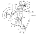
この糸掛けレバー20は、図3に示すように、その先端側に上糸供給源としての図示しない糸駒から前述の糸調子機構により繰出される糸を保持する糸保持部21を有する屈曲しているレバーであり、ミシン機枠に固定された軸22に基端部が回動可能に軸着されている。本実施形態において、前記糸掛けレバー20の本体は、一度その基端部から前記糸保持部21と反対の方向へ伸びた後、上方へ緩く弯曲するようにして折り返し、その先端部付近でクランク状に前記天秤体5の配設側へ突出するようにして形成されており、このクランク部20Aより先端側(以下、先端部材23という)は、クランク部20Aならびに基端部よりも上方に位置するように変位されて形成されている。さらに、前記先端部材23の先端上面には斜め前方に突出する糸保持用突出片24が一体形成されており、この糸保持用突出片24の下面が前記糸保持部21として機能するように構成されている。また、この糸保持用突出片24の先端部は前記天秤体5の配設側に鈎型に屈曲形成されて、後述する糸案内体25の外周縁26をガイドする糸案内体ガイド部27とされている。そして、前記先端部材23の先端面上部には突起状の糸受け部28が形成されており、前記糸保持用突出片24の下面とこの糸受け部28の上面とにより形成される凹部29を糸留りとして機能させるようになされている。
【0016】
そして、この糸掛けレバー20は、一端をミシン機枠に固定されたばね30によりその先端部が下方に付勢されており、ミシンの駆動モータの駆動により上下に移動する天秤体5の動きに追従し、前記天秤体5の軸部5aにその本体の下面20aを載置するように構成されている。
【0017】
前記糸調子機構と天秤体4との間における前記糸掛けレバー20の糸案内体ガイド部27の移動の軌跡の内側には、糸案内体25が配設されている。
【0018】
この糸案内体25は、ミシンの回転により上下に移動する天秤体5に追従する前記糸掛けレバー20の糸案内体ガイド部27の軌跡に沿った円弧状の外周縁26(以下、案内部31という)を有する略長方形状の板体であり、この案内部31の下方で前記糸掛けレバー20の糸案内体ガイド部27の下死点となる部分には、糸案内体ガイド部27が当接する平面を有する溝部33が形成されている。この溝部33は、前記糸案内体ガイド部27の当接部と前記案内部31の下方端部とを開口部34とし、弯曲状の内周面を有する形状に形成されており、この溝部33を構成する内周面のうち前記案内部31の下方端部に連接される部分は、糸案内体の後方に弧を描く曲面に形成され、前記底辺の後方端部に連接する部分は、その面の中間部まで垂設された後、糸案内体25の後方に弧を描くようにして形成されている。そして、糸案内体25の天秤体配設側の溝部30のほぼ中央部には、糸取りばね35が配置されており、この溝部35に案内された糸を保持して、天秤の糸締め、糸弛めに合せて糸のたるみを吸収するように構成されている。
【0019】
この糸案内体25の各部分と前記糸掛けレバー20の各部分との配設位置の関係をさらに詳しく説明すれば、図3に示すように、本実施形態において前記糸かけレバー20がストッパ36に保持された場合における糸掛けレバー20の前記凹部29は、糸案内体25の案内部31の上端部の外側に位置し、前記糸受け部28は、糸案内体25の案内部31の上端部の内側に位置する。一方、前記天秤体5の軸部5aが下死点にある場合における糸掛けレバー20の前記凹部29は、糸案内体25の溝部33に配設された糸取りばね35のやや上方に位置する。このとき、前記糸受け部28は、前記案内体31の溝部33から外れ、前述したように、糸掛けレバー20の糸案内体ガイド部27の先端が溝部33の底面に位置する。このような位置関係を取り得るように前記糸掛けレバー20と前記糸案内体25とが相互に関連配置されている。
【0020】
さらに、前記取付台7の正面上部には、板状の部材からなるストッパ36が横方向に延在し、水平方向に移動可能となるように配設されている。
【0021】
このストッパ36は、図2に示すように、その天秤体側端部36Aの上面がその中央部36Bの上面よりも高い位置となるようにこれらの天秤体側端部36Aと中央部36Bとの間に傾斜部36Cを設けて曲成されており、また、ストッパ36の前記天秤体側端部36Aの上面が前記天秤体5の軸部5aよりも上方に位置するように配設されている。そして、このストッパ36の天秤体側端面は下側が天秤体配設側が突出する上向きの斜面36aに形成されている。
【0022】
前記取付台7の側壁の上部には、前記ストッパ36の長手方向に間隔を隔てた水平方向に延在するガイド孔37a、37bが形成されている。また、前記ストッパ36の中央部36Bおよび前記天秤体側端部36Aと反対側の端部36Dの前記取付台7に対向する面には、前記ガイド孔37a、37bに挿入されるピン38a,38bが突設されている。さらに、前記ストッパ36の前記天秤体側端部36Aと反対側の端部36D付近の上面には、前記取付台7の正面上部から上方に突出する側壁39aと、この突出壁39aの上辺から取付台7の上面に沿うように屈曲し水平方向に延在する上壁39bとを有する突出片39が連設されており、この突出片39の上壁39bには、後述するアーム部材40に形成された長孔41に挿入されるピン42が上向きに突設されている。また、前記ストッパ36の中央部36Bの下面には、コイルばね43を係止する係止部44が形成されており、一方、前記取付台7の天秤体配設側端部にも前記コイルばね43を係止する係止部45が形成されている。そして、これらの両係止部44,45間に前記コイルばね43が張設されている。
【0023】
そして、通常時において、ストッパ36はこのコイルばね43により、前記天秤体側端部36Aを前記糸案内体25の方に突出させるように付勢されており、天秤体側端部の上面に前記糸掛けレバー20の先端部材23の下面23aを載置させることによって、ほぼ上下方向に移動するミシンの天秤機構の当接部、つまり、本実施形態においては図3に示すように、天秤体5の軸部5aより上方で保持するようになされている。
【0024】
また、取付台7に形成された前記軸18には前記ローラ圧接解除リンク17と同軸的にリンク46の中間部が軸支されており、そのリンク46の前記取付台7の正面側に位置する端部にはアーム部材40の基端部がピン32を介して回動可能に軸着されている。このアーム部材40の取付台7の上方で前記モータギア10と対向する側には、扇形をなすギア部47が前記ピン32と同心上に形成されており、そのギア部47の一方の側縁には板状のアーム本体48が前記ピン32からギア部47の径方向に延在するように一体形成されている。このアーム本体48の先端部には、その長手方向に延在する長孔41が形成されており、この長孔41には、前記ストッパ36の突出片39の上壁39bに形成されたピン42が摺動可能に挿入されている。一方、前記リンク46の後方端部にはばね49を係止するための係止部50が立設されており、この係止部50と前記取付台7の後方に形成した係止部51との間にコイルばね49を介在させることで、リンク46の前記係止部50の側辺を前記ローラ圧接解除リンク17に当接させるように付勢されている。
【0025】
なお、本実施形態においては、ミシン機枠には図示しない糸掛けスイッチが配設されており、このスイッチのON動作で前述した構成の糸掛け装置が駆動するように構成されている。
【0026】
次に、本実施形態の作用について説明する。
【0027】
本実施形態の糸掛け装置を駆動させる前に、まず最初に操作者が上糸Tのセットを行なう。
【0028】
通常、上糸Tのセットは、図示しないミシンの押え金を上昇させた状態で行なう。本実施形態においては、この押え金を上昇させる操作と連動して前記ローラ圧接解除リンク17が図1において矢印Aに示す方向に回転するように図示しないリンクが接続されており、押え金上昇時は、その状態が保たれるように構成されているものとする。
【0029】
ローラ圧接解除リンク17が、前述のように矢印A方向に回転すると、このローラ圧接解除リンク17に連接された従動ローラ取付板14はミシン機枠の後方へ摺動移動することとなり、従動ローラ取付板14に取付けられた従動ローラ16a,16bは駆動ローラ11に対する圧接を解除され、その結果、従動ローラ16a,16bと駆動ローラ11との間に間隙が発生する。
【0030】
そこで、操作者は、ミシン機枠の所定位置に、上糸Tの供給源としての糸駒をセットし、糸駒から上糸Tを引き出して、従動ローラ16a,16bと駆動ローラ11との間隙に糸を通した後、図3に示すように、糸掛けレバー20の前記糸保持部21に上糸Tを掛ける。続いて、図1乃至図3に示すように、糸掛けレバー20の左側に配設され、そのストロークの上死点付近に位置する天秤体5の天秤糸道5bに上糸Tを掛け通す。
【0031】
このように、本実施形態における糸掛け装置のセッティングは、操作者が上糸Tを手にして糸を上側へ引いたり、下側へ引いたりすることをせずに、簡単に行なうことができる。
【0032】
次に、図示しない前記糸掛けスイッチをONにする。すると、前記上糸繰出しモータ8およびモータギア10が図1の矢印B方向に回転駆動する。
【0033】
このとき、前述したミシンの押え金の上昇に伴ってローラ圧接解除リンク17が矢印A方向に回転することにより、従動ローラ取付板14の移動を介して前記モータギア10に対する従動ローラ16a,16bの駆動ギア13の噛合は解除され、逆に、前記ローラ圧接解除リンク17に連接されたリンク46がコイルばね49の付勢力によりローラ解除リンク17との連接を維持するように回動して、前記モータギア10とアーム部材40のギア部47とが噛合し、アーム部材40も図1の矢印B方向に回動することとなる。前述のように、アーム部材40のアーム本体48に形成された長孔41には、ストッパ36の突出片39の上面39bに形成されたピン42が挿入されており、前記アーム部材40のアーム本体48が矢印B方向に回動することによって、配設されたコイルばね43の付勢に抵抗しつつ、前記ストッパ36もピン42によって矢印B方向に移動する。このとき、ストッパ36は、その取付台7に対向する面に形成されたピン38a,38bを取付台7に形成されたガイド孔37に沿わせて水平方向に正確に移動する。
【0034】
ストッパ36が矢印B方向に移動することにより、ストッパ36による糸掛けレバー20の保持が解除されることとなる。保持が解除された糸掛けレバー20は、糸掛けレバー20を下方に付勢するばね30により、前記軸22を中心に回転され、その糸掛けレバー20の本体下面20aを上死点に位置している天秤体5の軸部5aに当接させて係止させる。
【0035】
次に、この状態で、ミシン本体の駆動モータを低速で回転させる。この回転により前記天秤体5がその上死点から下方に向かって回動を開始する。すると、前記糸掛けレバー20も天秤体5の動きに追従して降下を始める。なお、糸掛けレバー20の糸案内体ガイド部27が、糸案内体25の案内部31をに沿って移動することは前述の通りである。
【0036】
このとき、上糸Tは糸掛けレバー20の糸保持部21により糸案内体25の案内部31に沿って下方に運ばれ、前記天秤体5が下死点に到達して糸掛けレバー20の糸案内体ガイド部27が前記溝部33の底面32に当接すると、上糸Tは糸保持用突出片24の下面である糸保持部21に沿って、前記溝部33に導入される。
【0037】
その後、前記駆動モータの駆動により、前記天秤体5がその下死点から上方に向かって回動を開始すると、糸掛けレバー20も前記軸部5aに当接しながら前記天秤体5の上方に向かう回動にともなってばね28の付勢力に抵抗しつつ上昇を始める。
【0038】
そのとき、溝部33内に導入された上糸Tは、その天秤糸道5bに上糸Tを通した天秤体5の上昇によって、溝部33内で上方に引かれ、その溝部33の糸取りばね35に係合することとなる。
【0039】
前述のミシン本体の駆動モータは、図示しない制御手段により、前記天秤体5を1ストロークさせるのみでその回転を停止するように制御されており、さらに、前記上糸繰出しモータ8およびモータギア10を、この駆動モータの停止を待って矢印Bと反対方向へ回転して停止するように制御する。よって、天秤体5の軸5aがその上死点に位置したときに、この軸5aに当接させている糸掛けレバー20の本体下面より上方に変位している先端部材23の下方近傍に、前記ストッパ36がその天秤配設側に形成された上向きの斜面36aの先端部から差込まれる。つまり、前記上糸繰出しモータ8およびモータギア10の逆回転により図1の矢印B方向への移動が解除された前記ストッパ36は、ばね43の付勢力により、再び、その天秤配設側に形成された上向きの斜面36aの先端部を突出させて位置することとなる。このとき、まず、前記斜面36aが糸掛けレバー20の先端部材23の下面に当接する。そして、前記上糸繰出しモータ8およびモータギア10が逆回転するにつれてさらに大きく天秤体配設側に突出する際に、前記糸掛けレバー20を前記斜面36aに沿ってすべらせるようにしてストッパ36の上面に押上げる。そして、最終的には、前記糸掛けレバー20を当接していた軸5aから離間させ、そのストッパ36の上面に保持する。
【0040】
そして、その後、図示しない針棒の針穴に上糸Tを通し、通常のミシンの駆動を開始して、縫製を行なう。
【0041】
以上、説明したように、本発明の実施形態によれば、糸取りばね35への糸掛けを人手によって行なわずに済み、図示しない糸掛けスイッチのON動作で簡単に行なうことができる。また、糸取りばね35への糸掛けを行なう糸掛けレバー20は、通常のミシンの駆動時においては移動する天秤体5の上方に保持されており、また、糸取りばね35が配設された糸案内体25も薄い板上の部材であるので、糸取りばね35の周辺の構造を簡略化することを可能とする。
【0042】
また、前記糸掛けレバー20の駆動は、配設されたばね30とミシン本体のモータの回転による天秤体5の動きに依存し、前記ストッパ36の駆動は、上糸繰出しモータ8を兼用することとしたので、別段、新規なモータを搭載する必要もなく、安価に糸掛け装置を構成することができる。
【0043】
なお、本発明は前記実施形態のものに限定されるものではなく、必要に応じて種々変更することが可能である。例えば、ストッパ36の駆動は、上糸繰出しモータ8以外のアクチュエータとの兼用でも可能であるし、経費を考えなければ、専用のアクチュエータを搭載してもよい。また、前述の実施形態において、糸掛けレバー20は、天秤体5の軸部5aに追従する構成としたが、天秤支え6や天秤体5の他の部分に追従する構成でもよいことはいうまでもない。
【0044】
【発明の効果】
以上述べたように本発明に係るミシンの糸掛け装置によれば、糸取りばねへの糸掛けを人手によって行なわずに簡単に行なうことができ、糸掛け装置を構成する各部材も通常の動作に支障のないところに配設、保持することとし、糸取りばねの周辺の構造を簡略化することができるとともに、既存の部材を兼用することで安価に糸掛け装置を構成することができる等の効果を奏する。
【図面の簡単な説明】
【図1】本発明に係るミシンの糸掛け装置の一実施形態を示す平面図
【図2】本発明に係るミシンの糸掛け装置の一実施形態を示す正面図
【図3】本発明に係るミシンの糸掛け装置の一実施形態の要部構造を示す断面図
【図4】従来のミシンの糸掛け手順を示す正面図
【図5】従来のミシンの糸掛け装置の一実施形態の要部構造を示す説明図
【符号の説明】
1 主軸
2 釣合錘
3 針棒クランク
4 針棒クランクロッド
5 天秤体
6 天秤支え
7 取付台
8 上糸繰出しモータ
9 モータ軸
10 モータギア
11 駆動ローラ
12 ローラ軸
13 駆動ギア
14 従動ローラ取付板
15 軸
16 従動ローラ
17 ローラ圧接解除リンク
17a 屈曲部
18 軸部
19 引張りばね
20 糸掛けレバー
20A クランク部
21 糸保持部
22 軸
23 先端部材
24 糸保持用突出片
25 糸案内体
26 外周縁
27 糸案内体ガイド部
28 糸受け部
30 ばね
31 案内部
32 ピン
33 溝部
34 開口部
35 糸取りばね
36 ストッパ
37 ガイド孔
38 ピン
39 突出片
39a 側壁
39b 上壁
40 アーム部材
41 長孔
42 ピン
43 コイルばね
44 係止部
45 係止部
46 リンク
47 ギア部
48 アーム本体
49 コイルばね
50 係止部
51 係止部
T 上糸[0001]
BACKGROUND OF THE INVENTION
The present invention relates to a threading device for a sewing machine, and more particularly to a threading device for a sewing machine that automatically performs threading of a sewing machine to a thread take-up spring.
[0002]
[Prior art]
Conventionally, as shown in FIG. 4, for example, as shown in FIG. 4, a
[0003]
[Problems to be solved by the invention]
The conventional threading of the sewing machine is very troublesome because the threading is performed manually by moving the thread up and down in the order described above.
[0004]
Thereafter, in order to omit manual threading operation to the thread take-
[0005]
The present invention has been made in view of the above-described points, and automatically performs threading of the sewing machine with respect to the thread take-up spring, thereby making it possible to omit a complicated procedure of threading and making a mechanically simple sewing machine. An object of the present invention is to provide a yarn hooking device.
[0006]
[Means for Solving the Problems]
In order to achieve the above object, a threading device for a sewing machine according to claim 1 of the present invention has a movable thread holding portion that holds a thread fed from an upper thread supply source by a thread tension mechanism. A yarn hooking lever that abuts on a balance mechanism that moves substantially in the vertical direction by rotation and can follow the movement, and below the guide portion that is formed along the outer periphery of the yarn holding portion along the locus of movement. It is held by a thread holding part of the threading lever that moves in the vertical direction while following the movement of the balance mechanism by the rotation of the sewing machine, and is conveyed along the guide part. A thread guide that guides the thread into the groove and engages with the thread take-up spring; and a lower surface of the thread hooking lever that is spaced apart from a contact part that follows the balance mechanism; Above the guide part of the thread guide A stopper that holds the threading lever, and releases the holding of the threading lever by the stopper when threading the threading spring, and operates the holding of the threading lever by the stopper at the end of threading the threading spring. And a stopper driving mechanism.
[0007]
According to a second aspect of the present invention, there is provided the threading device for the sewing machine according to the first aspect, wherein the thread tension mechanism includes an upper thread feeding motor having a motor gear and a motor gear of the upper thread feeding motor. A driving roller that is coaxially disposed with a driving gear meshing with the driving roller, a driven roller that is press-contactable / separable to the driving roller and biased in a direction to press-contact the driving roller by a spring, and a biasing force of the spring The roller pressure contact release link separates the driven roller from the drive roller.
[0008]
According to a third aspect of the present invention, there is provided the sewing machine threading device according to the second aspect, wherein the stopper driving mechanism includes a link connected to the roller pressure release release link, the link and the stopper. And an arm member formed with a gear portion that meshes with the motor gear only when the driven roller is separated from the drive roller, and the stopper engages the thread hook when the sewing machine is driven. The stopper is biased by a spring so as to lock the lever.
[0009]
According to the threading device of the sewing machine of the present invention, it is possible to thread the thread take-up spring by driving the threading lever following the balance mechanism only when the driven roller is separated, and when the driven roller is pressed. The stopper can hold the yarn hooking lever at a position that does not hinder the movement of the balance mechanism.
[0010]
DETAILED DESCRIPTION OF THE INVENTION
Hereinafter, an exemplary embodiment of the present invention will be described with reference to FIGS. 1 to 3.
[0011]
In this embodiment, a main shaft 1, a
[0012]
As shown in FIG. 1 (plan view) and FIG. 2 (front view), the thread tension mechanism of the present embodiment has an upper thread feeding motor on the lower surface of a
[0013]
A driven
[0014]
In the present embodiment, a
[0015]
As shown in FIG. 3, the
[0016]
The
[0017]
A
[0018]
The
[0019]
If the relationship between the arrangement positions of each part of the
[0020]
Further, a
[0021]
As shown in FIG. 2, the
[0022]
In the upper part of the side wall of the mounting
[0023]
In a normal state, the
[0024]
An intermediate portion of the
[0025]
In this embodiment, a threading switch (not shown) is provided in the sewing machine frame, and the threading device having the above-described configuration is driven by the ON operation of this switch.
[0026]
Next, the operation of this embodiment will be described.
[0027]
Before driving the yarn hooking device of this embodiment, the operator first sets the upper thread T.
[0028]
Usually, the upper thread T is set in a state where a presser foot of a sewing machine (not shown) is raised. In this embodiment, a link (not shown) is connected so that the roller pressure
[0029]
When the roller
[0030]
Therefore, the operator sets a yarn spool as a supply source of the upper thread T at a predetermined position of the sewing machine frame, pulls the upper thread T out of the thread spool, and the gap between the driven rollers 16a and 16b and the driving
[0031]
As described above, the setting of the yarn hooking device in this embodiment can be easily performed without the operator pulling the yarn upward or pulling the yarn upward with the upper thread T in hand. .
[0032]
Next, the threading switch (not shown) is turned on. Then, the upper
[0033]
At this time, the roller
[0034]
When the
[0035]
Next, in this state, the drive motor of the sewing machine body is rotated at a low speed. By this rotation, the
[0036]
At this time, the upper thread T is conveyed downward along the
[0037]
Thereafter, when the
[0038]
At this time, the upper thread T introduced into the
[0039]
The drive motor of the above-described sewing machine body is controlled by a control means (not shown) to stop the rotation of the
[0040]
Thereafter, the upper thread T is passed through a needle hole of a needle bar (not shown), and a normal sewing machine is started to perform sewing.
[0041]
As described above, according to the embodiment of the present invention, it is not necessary to manually thread the thread take-up
[0042]
Further, the driving of the
[0043]
In addition, this invention is not limited to the thing of the said embodiment, A various change is possible as needed. For example, the
[0044]
【The invention's effect】
As described above, according to the threading device for a sewing machine according to the present invention, it is possible to easily perform threading on the thread take-up spring without manual operation, and each member constituting the threading device also performs normal operation. It is possible to arrange and hold it in a place where there is no hindrance, simplify the structure around the thread take-up spring, and at the same time use the existing member to construct a yarn hooking device at low cost. Play.
[Brief description of the drawings]
FIG. 1 is a plan view showing an embodiment of a threading device for a sewing machine according to the present invention. FIG. 2 is a front view showing an embodiment of a threading device for a sewing machine according to the present invention. FIG. 4 is a front view showing a conventional threading procedure of a sewing machine. FIG. 5 is a cross-sectional view showing the main part structure of an embodiment of a threading device for a sewing machine. Explanatory drawing showing the structure
DESCRIPTION OF SYMBOLS 1
Claims (3)
前記糸保持部の移動の軌跡に沿って形成された外周縁からなる案内部の下方に糸取りばねを配した溝部を有しミシンの回転により前記天秤機構の動きに追従しつつほぼ上下方向に移動する前記糸掛けレバーの糸保持部に保持されて前記案内部に沿って搬送される上糸を前記溝部に案内して前記糸取りばねに係合させる糸案内体と、
前記糸掛けレバーの下面を前記天秤機構に追従する際の当接部から上方に離間させるとともに、糸保持部を前記糸案内体の案内部の上方に位置させて前記糸掛けレバーを保持するストッパと、
前記糸取りばねに対する糸掛け時には前記ストッパによる糸掛けレバーの保持を解除し、糸取りばねに対する糸掛け終了時には前記ストッパによる糸掛けレバーの保持の作動を行なうストッパ駆動機構と
を有することを特徴とするミシンの糸掛け装置。A yarn having a movable yarn holding portion for holding a yarn fed from an upper yarn supply source by a yarn tensioning mechanism and abutting on a balance mechanism that moves substantially in the vertical direction by the rotation of the sewing machine, and can follow the movement. A hanging lever,
It has a groove part with a thread take-up spring below the guide part consisting of the outer peripheral edge formed along the locus of movement of the thread holding part, and moves substantially vertically while following the movement of the balance mechanism as the sewing machine rotates. A yarn guide body that guides the upper yarn held by the yarn holding portion of the yarn hooking lever and conveyed along the guide portion to the groove portion and engages with the thread take-up spring;
A stopper that holds the yarn hooking lever by separating the lower surface of the yarn hooking lever upward from the contact portion when following the balance mechanism and positioning the yarn holding portion above the guide portion of the yarn guide body. When,
A sewing machine comprising: a stopper driving mechanism that releases the holding of the yarn hooking lever by the stopper when threading the yarn take-up spring, and that holds the yarn hooking lever by the stopper when the yarn hooking spring is finished. Threading device.
Priority Applications (1)
| Application Number | Priority Date | Filing Date | Title |
|---|---|---|---|
| JP15408496A JP3830207B2 (en) | 1996-06-14 | 1996-06-14 | Sewing thread threading device |
Applications Claiming Priority (1)
| Application Number | Priority Date | Filing Date | Title |
|---|---|---|---|
| JP15408496A JP3830207B2 (en) | 1996-06-14 | 1996-06-14 | Sewing thread threading device |
Publications (2)
| Publication Number | Publication Date |
|---|---|
| JPH10288A JPH10288A (en) | 1998-01-06 |
| JP3830207B2 true JP3830207B2 (en) | 2006-10-04 |
Family
ID=15576549
Family Applications (1)
| Application Number | Title | Priority Date | Filing Date |
|---|---|---|---|
| JP15408496A Expired - Fee Related JP3830207B2 (en) | 1996-06-14 | 1996-06-14 | Sewing thread threading device |
Country Status (1)
| Country | Link |
|---|---|
| JP (1) | JP3830207B2 (en) |
-
1996
- 1996-06-14 JP JP15408496A patent/JP3830207B2/en not_active Expired - Fee Related
Also Published As
| Publication number | Publication date |
|---|---|
| JPH10288A (en) | 1998-01-06 |
Similar Documents
| Publication | Publication Date | Title |
|---|---|---|
| JPH11333182A (en) | Thread drawing device for sewing machine | |
| US20130152838A1 (en) | Sewing Machine | |
| JP4029643B2 (en) | sewing machine | |
| US8215249B2 (en) | Sewing machine | |
| JPH02152495A (en) | Upper thread drawing device of sewing machine | |
| JP3830207B2 (en) | Sewing thread threading device | |
| JP2010088760A (en) | Needle threader for sewing machine | |
| JPH08173677A (en) | Threading unit for sewing machine | |
| US7314013B2 (en) | Sewing machine | |
| US5086718A (en) | Sewing machine with automatic thread take-up and threading | |
| JP6216556B2 (en) | Sewing machine threader and sewing machine | |
| JP2969685B2 (en) | Automatic threading threader | |
| JP3737584B2 (en) | Sewing machine threading device | |
| JP2004223005A (en) | Attachment of sewing machine | |
| US20110048302A1 (en) | Sewing machine provided with auxiliary table | |
| JP2000271372A (en) | Threading device for sewing machine | |
| US6860212B2 (en) | Threading apparatus for sewing machine | |
| JP3691918B2 (en) | Sewing machine threading device | |
| JP3382898B2 (en) | Sewing machine with threader | |
| JP3730300B2 (en) | Sewing machine threading device | |
| JP3986142B2 (en) | Embroidery sewing machine | |
| CN113005661B (en) | Method for controlling length stability of thread end in sewing machine needle | |
| JP3797292B2 (en) | Yarn hooking device for yarn guide and sewing machine equipped with this yarn hooking device | |
| JP4608989B2 (en) | Sewing needle thread guide | |
| JPH04317691A (en) | Cloth feeding device of sewing machine |
Legal Events
| Date | Code | Title | Description |
|---|---|---|---|
| A977 | Report on retrieval |
Free format text: JAPANESE INTERMEDIATE CODE: A971007 Effective date: 20060531 |
|
| TRDD | Decision of grant or rejection written | ||
| A01 | Written decision to grant a patent or to grant a registration (utility model) |
Free format text: JAPANESE INTERMEDIATE CODE: A01 Effective date: 20060620 |
|
| A61 | First payment of annual fees (during grant procedure) |
Free format text: JAPANESE INTERMEDIATE CODE: A61 Effective date: 20060711 |
|
| R150 | Certificate of patent or registration of utility model |
Free format text: JAPANESE INTERMEDIATE CODE: R150 |
|
| LAPS | Cancellation because of no payment of annual fees |