JP3827552B2 - Seamless belt with guide - Google Patents
Seamless belt with guide Download PDFInfo
- Publication number
- JP3827552B2 JP3827552B2 JP2001326504A JP2001326504A JP3827552B2 JP 3827552 B2 JP3827552 B2 JP 3827552B2 JP 2001326504 A JP2001326504 A JP 2001326504A JP 2001326504 A JP2001326504 A JP 2001326504A JP 3827552 B2 JP3827552 B2 JP 3827552B2
- Authority
- JP
- Japan
- Prior art keywords
- guide
- seamless belt
- bonded
- adhesive layer
- peripheral surface
- Prior art date
- Legal status (The legal status is an assumption and is not a legal conclusion. Google has not performed a legal analysis and makes no representation as to the accuracy of the status listed.)
- Expired - Fee Related
Links
- 239000012790 adhesive layer Substances 0.000 claims description 24
- 230000002093 peripheral effect Effects 0.000 claims description 18
- 229920005989 resin Polymers 0.000 claims description 11
- 239000011347 resin Substances 0.000 claims description 11
- 230000003014 reinforcing effect Effects 0.000 claims description 5
- 238000004519 manufacturing process Methods 0.000 description 5
- 239000002390 adhesive tape Substances 0.000 description 4
- 230000000694 effects Effects 0.000 description 4
- 238000010008 shearing Methods 0.000 description 4
- 238000012360 testing method Methods 0.000 description 4
- 229920005992 thermoplastic resin Polymers 0.000 description 3
- 229920001187 thermosetting polymer Polymers 0.000 description 3
- 239000004962 Polyamide-imide Substances 0.000 description 2
- 239000003522 acrylic cement Substances 0.000 description 2
- 230000000052 comparative effect Effects 0.000 description 2
- 238000009499 grossing Methods 0.000 description 2
- 238000000465 moulding Methods 0.000 description 2
- 229920002312 polyamide-imide Polymers 0.000 description 2
- 239000000843 powder Substances 0.000 description 2
- 229920002803 thermoplastic polyurethane Polymers 0.000 description 2
- 238000012546 transfer Methods 0.000 description 2
- 239000004925 Acrylic resin Substances 0.000 description 1
- 229920000178 Acrylic resin Polymers 0.000 description 1
- OKTJSMMVPCPJKN-UHFFFAOYSA-N Carbon Chemical compound [C] OKTJSMMVPCPJKN-UHFFFAOYSA-N 0.000 description 1
- 229920000459 Nitrile rubber Polymers 0.000 description 1
- 239000004642 Polyimide Substances 0.000 description 1
- 239000004820 Pressure-sensitive adhesive Substances 0.000 description 1
- 230000005856 abnormality Effects 0.000 description 1
- 238000005299 abrasion Methods 0.000 description 1
- NIXOWILDQLNWCW-UHFFFAOYSA-N acrylic acid group Chemical group C(C=C)(=O)O NIXOWILDQLNWCW-UHFFFAOYSA-N 0.000 description 1
- 239000000853 adhesive Substances 0.000 description 1
- 230000001070 adhesive effect Effects 0.000 description 1
- 239000002313 adhesive film Substances 0.000 description 1
- 230000002411 adverse Effects 0.000 description 1
- 229910052782 aluminium Inorganic materials 0.000 description 1
- XAGFODPZIPBFFR-UHFFFAOYSA-N aluminium Chemical compound [Al] XAGFODPZIPBFFR-UHFFFAOYSA-N 0.000 description 1
- 239000002216 antistatic agent Substances 0.000 description 1
- 239000006229 carbon black Substances 0.000 description 1
- 239000000919 ceramic Substances 0.000 description 1
- 238000011161 development Methods 0.000 description 1
- 239000003822 epoxy resin Substances 0.000 description 1
- 238000011156 evaluation Methods 0.000 description 1
- 239000010439 graphite Substances 0.000 description 1
- 229910002804 graphite Inorganic materials 0.000 description 1
- 239000010410 layer Substances 0.000 description 1
- 239000002184 metal Substances 0.000 description 1
- 229910052751 metal Inorganic materials 0.000 description 1
- 238000000034 method Methods 0.000 description 1
- 108091008695 photoreceptors Proteins 0.000 description 1
- 229920000515 polycarbonate Polymers 0.000 description 1
- 239000004417 polycarbonate Substances 0.000 description 1
- 229920000647 polyepoxide Polymers 0.000 description 1
- 229920001721 polyimide Polymers 0.000 description 1
- 229920000642 polymer Polymers 0.000 description 1
- 230000002787 reinforcement Effects 0.000 description 1
- 239000000758 substrate Substances 0.000 description 1
- 229920002725 thermoplastic elastomer Polymers 0.000 description 1
- 229920006337 unsaturated polyester resin Polymers 0.000 description 1
Images

Landscapes
- Electrophotography Configuration And Component (AREA)
- Electrostatic Charge, Transfer And Separation In Electrography (AREA)
- Structure Of Belt Conveyors (AREA)
- Belt Conveyors (AREA)
Description
【0001】
【発明の属する技術分野】
本発明は、電子写真複写機、レーザープリンタ、ファクシミリ、あるいはこれらを複合したOA機器に使用されるガイド付きシームレスベルトに関するものである。
【0002】
【従来の技術】
従来のガイド付きシームレスベルトは、図3に示すように、シームレスベルト1と、このシームレスベルト1の内周面一側部に周方向に向けて貼着されるガイド2とを備え、複数のロール10間に巻架して中間転写ベルト等として利用される。
シームレスベルト1は屈曲可能な可撓性のエンドレスに成形される。また、ガイド2は、細長い線条に形成され、両端部が隙間を介し近接対向して継目を形成しており、各ロール10の一側部にエンドレスに形成された嵌合溝11に嵌合する。
【0003】
以上のように構成されたガイド付きシームレスベルトは、複数のロール10の回転に伴い循環する。この際、ガイド2には、嵌合溝11の内外周差等によりせん断力等が否応なく作用するが、ガイド2の非端部に関しては作用と反作用の相殺により特に悪影響を受けることがない。したがって、ガイド2は、シームレスベルト1の蛇行を有効に規制する。
【0004】
【発明が解決しようとする課題】
従来のガイド付きシームレスベルトは、以上のように構成され、例えガイド2にせん断力等が作用しても、ガイド2の非端部に関しては特に大きな問題の生じることはない。
しかしながら、ガイド2の端部はなんら連続しないので、ここにせん断力が作用すると、ガイド2の端部が隅から徐々に剥がれることとなる。これをそのまま放置すると、剥離が拡大してガイド2が短期間のうちにロール10の嵌合溝11から外れたり、シームレスベルト1とロール10の間にガイド2の端部が挟まれてシームレスベルト1が破損したり、あるいは装置が停止してしまうという問題がある。
【0005】
本発明は上記に鑑みなされたもので、例えガイドの端部が剥がれても、ガイドがロール等から外れたり、シームレスベルトとロール等の間にガイドの端部が挟まれてシームレスベルトが破損等するのを有効に抑制防止することのできるガイド付きシームレスベルトを提供することを目的としている。
【0006】
【課題を解決するための手段】
本発明においては上記課題を解決するため、エンドレスに成形されて複数のロール間に巻き掛け渡される可撓性のシームレスベルトと、このシームレスベルトの少なくとも内周面一側部に接着され、ロールの一側部に形成されたエンドレスの嵌合溝に嵌め合わされる略線条のガイドとを備え、このガイドを、シームレスベルトの内周面に粘接着層を介して接着される樹脂フィルムと、この樹脂フィルムに接着されるガイド本体とから構成してシームレスベルトの周方向に向けて接着し、このガイドの両端部間を隙間を介して対向させたものであって、
ガイドの両端部間に、シームレスベルトの内周面に隙間を介して対向する可撓性の片面当て板を架設して当て板継ぎし、この片面当て板を、ガイド本体の両端部間に橋架して接着され、シームレスベルトの内周面に隙間を介して対向する粘接着層と、この粘接着層に積層して接着される補強フィルムとから構成したことを特徴としている。
【0007】
ここで、特許請求の範囲におけるガイドは、シームレスベルトの内周面一側部に接着されるものでも良いし、シームレスベルトの内周面両側部にそれぞれ接着されるものでも良い。この接着には粘着が含まれる。また、本発明に係るガイド付きシームレスベルトは、OA機器の中間転写ベルトとして主に利用されるが、感光体基体用、用紙搬送用、現像用、定着用等の用途でも良い。
【0008】
【発明の実施の形態】
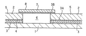
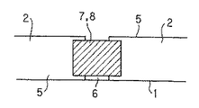
以下、図面を参照して本発明の好ましい実施形態を説明すると、本実施形態におけるガイド付きシームレスベルトは、図1、図2に示すように、シームレスベルト1の内周面一側部に、ガイド2を接着層である粘接着層3により周方向に接着してその両端部を隙間を介して突き合わせ、このガイド2の両端部間に、可撓性・柔軟性の片面当て板7を架設して当て板継ぎするようにしている。
【0009】
シームレスベルト1は、所定の熱硬化性樹脂や熱可塑性樹脂を材料とする遠心成形法により可撓性を有するエンドレスの円筒形に成形され、複数のロール10間に屈曲して巻架される。熱硬化性樹脂としては、エポキシ樹脂、アクリル樹脂、不飽和ポリエステル樹脂等があげられる。また、熱可塑性樹脂としては、ポリイミド、ポリアミドイミド、ポリカーボネート等があげられる。これら熱硬化性樹脂や熱可塑性樹脂には、カーボンブラック、グラファイト、金属粉、導電性セラミック粉、ポリマー型帯電防止剤が分散混合され、静電付着に必要な半導電性が付与された樹脂が適宜使用される。
【0010】
ガイド2は、シームレスベルト1の内周面に両面粘着テープ等からなる粘接着層3を介して接着されるPET等の樹脂フィルム4と、この樹脂フィルム4に両面粘着テープからなる粘接着層3Aを介して接着される弾性のガイド本体5とから断面略矩形の細長い帯形、線条に形成され、両端部が隙間を介し近接対向して継目6を形成しており、各ロール10の一側部にエンドレスに形成された嵌合溝11に嵌合してシームレスベルト1の蛇行を規制する。ガイド本体5は、機械的強度や耐磨耗性に優れるウレタン樹脂、NBR、熱可塑性エラストマー等を使用して硬度(JIS A)50〜80°に形成される。
【0011】
さらに、片面当て板7は、ガイド本体5の両端部間に橋架して接着される両面粘着テープからなる粘接着層3Bと、この粘接着層3Bに積層して接着される補強フィルム8とから断面略矩形の長方形に形成される。補強フィルム8としては、例えば寸法安定性、引張り強さ、機械特性、耐磨耗性等に優れるPET等が好適に使用される。
【0012】
上記構成によれば、例えロール10の回転によりせん断力が作用してガイド2の端部が剥がれても、ガイド2の端部を橋かけ構造の片面当て板7で補強してガイド2の端部が自由に揺れ動くのを規制するので、簡易な構成でガイド2がロール10の嵌合溝11から外れるおそれをきわめて有効に抑制することができる。また、片面当て板7が剥離するガイド2の両端部を接続して押さえ付けるので、シームレスベルト1とロール10との間にガイド2が挟まれ、シームレスベルト1が破損したり、装置が停止するのを有効に抑制防止することができる。また、粘接着層3によりシームレスベルト1の内周面にガイド2を接着するので、製造作業の円滑化、簡素化、迅速化、容易化が大いに期待できる。同様に、粘接着層3Bによりガイド本体5に片面当て板7を接着するので、製造作業の円滑化、簡素化、迅速化、容易化が大いに期待できる。
【0013】
なお、片面当て板7は、正方形、台形、楕円形、小判形等の形状でも良い。また、ガイド2の端部の剥離を減少させるため、ガイド2の端部の面積を広くしたり、剛性を増したり、あるいは端部を薄くしても良い。
【0014】
【実施例】
以下、本発明に係るガイド付きシームレスベルトの実施例を比較例と共に説明する。
ガイド付きシームレスベルトの作製
先ず、ポリアミドイミドを使用した遠心成形法によりシームレスベルトをL230mm、φ250mm、t0.10mmの大きさに成形し、このシームレスベルトの内周面一側部に線条のガイドをアクリル系粘着剤からなる粘接着層により周方向に接着し、L782mm、幅5mmにカットした。
ガイドについては、粘接着層により接着されるPET(t75μm)からなる樹脂フィルムと、この樹脂フィルムに両面粘着テープからなる粘接着層を介して接着されるガイド本体とから形成した。ガイド本体としては、ウレタン樹脂(t1.0mm、JIS A硬度75)を使用し、アクリル系粘着剤はt15μmとした。
【0015】
シームレスベルトの内周面にガイドを接着したら、ガイドの両端部を隙間を介して突き合わせ、このガイドの内周面両端部間に、幅4mm×長さ5mmの片面当て板を架設して当て板継ぎし、その後、この片面当て板を幅方向、長手方向共、略対称になるよう位置合わせしてガイド付きシームレスベルトを作製した。
片面当て板については、ガイド本体の両端部間に橋架して接着されるアクリル系粘着剤からなる粘接着層(t15μm)と、この粘接着層に接着されるPET(t75μm)からなる補強フィルムとから形成した。
【0016】
耐久性試験
ガイド付きシームレスベルトを作製したら、従来のガイド付きシームレスベルトと共に耐久性試験を実施し、実施例と従来の比較例の効果を検討評価した。この耐久性試験の具体的な内容としては、一対のロール間にガイド付きシームレスベルトを懸架して5kgfの荷重を加え、ガイド付きシームレスベルトを回転速度15回転/分で循環させた。各ロールはφ25mmのアルミニウム製とした。このロールの嵌合溝は、ロールの端部から15mmの個所を中心に、幅5.2mm、深さ1.1mmに形成した。
効果の検討に際しては、1万回転までは1000回転毎に、1万回転からは1万回転毎にそれぞれ状態を確認し、異常があれば、前回確認した回転数をもって評価結果とした。
【0017】
耐久性試験の結果、実施例のガイド付きシームレスベルトの場合には、60万回転でガイドの端部に微小な剥離が生じ、80万回転でガイドの端部が2cm程度まで剥離した。しかしながら、100万回転まではガイドがロールの嵌合溝から外れることがなく、シームレスベルトとロールとの間にガイドが挟まれ、シームレスベルトが破損したり、装置の停止を招くことがなかった。
これに対し、片面当て板を有しない従来のガイド付きシームレスベルトの場合、3万回転でガイドの端部に剥離が生じ、4万回転で剥離したガイドの端部がロールの嵌合溝から外れ、シームレスベルトとロールとの間にガイドが挟まれてシームレスベルトが破損した。
【0018】
【発明の効果】
以上のように本発明によれば、例えガイドの端部が剥がれても、ガイドがロール等から外れたり、シームレスベルトとロール等の間にガイドの端部が挟まれてシームレスベルトが破損等するのを有効に抑制防止することができるという効果がある。具体的には、片面当て板が剥離するガイドの両端部を接続して押さえ付けるので、シームレスベルトとロールとの間にガイドが挟まれ、シームレスベルトが破損したり、装置が停止するのを有効に抑制することができる。また、粘接着層によりシームレスベルトの内周面にガイドを接着するので、製造作業の円滑化、簡素化、迅速化、容易化を図ることができる。同様に、粘接着層によりガイド本体に片面当て板を接着するので、製造作業の円滑化、簡素化、迅速化、容易化が期待できる。
【図面の簡単な説明】
【図1】本発明に係るガイド付きシームレスベルトの実施形態を示す要部断面側面図である。
【図2】本発明に係るガイド付きシームレスベルトの実施形態を示す平面図である。
【図3】ガイド付きシームレスベルトの使用状態を示す斜視説明図である。
【符号の説明】
1 シームレスベルト
2 ガイド
3 粘接着層
3A 粘接着層
3B 粘接着層
4 樹脂フィルム
5 ガイド本体
7 片面当て板
8 補強フィルム
10 ロール
11 嵌合溝[0001]
BACKGROUND OF THE INVENTION
The present invention relates to a seamless belt with a guide for use in an electrophotographic copying machine, a laser printer, a facsimile, or an OA device combining these.
[0002]
[Prior art]
As shown in FIG. 3, a conventional seamless belt with a guide includes a seamless belt 1 and a
The seamless belt 1 is formed into a flexible endless bendable. Further, the
[0003]
The guided seamless belt configured as described above circulates as the plurality of
[0004]
[Problems to be solved by the invention]
A conventional seamless belt with a guide is configured as described above, and even if a shearing force or the like is applied to the
However, since the end portion of the
[0005]
The present invention has been made in view of the above. Even if the end portion of the guide is peeled off, the guide is detached from the roll or the like, or the end portion of the guide is sandwiched between the seamless belt and the roll or the like, and the seamless belt is damaged. It is an object of the present invention to provide a seamless belt with a guide that can effectively suppress and prevent the operation.
[0006]
[Means for Solving the Problems]
In the present invention, in order to solve the above-mentioned problem, a flexible seamless belt formed endlessly and wound around a plurality of rolls is bonded to at least one side of the inner peripheral surface of the seamless belt. A substantially linear guide fitted in an endless fitting groove formed on one side, and this guide is bonded to the inner peripheral surface of the seamless belt via an adhesive layer; It is composed of a guide body that is bonded to this resin film, and is bonded toward the circumferential direction of the seamless belt, and is opposed to both ends of the guide via a gap,
A flexible single-sided contact plate facing the inner peripheral surface of the seamless belt through a gap is installed between both ends of the guide and joined, and this single-sided contact plate is bridged between both ends of the guide body. The adhesive layer is composed of an adhesive layer that is bonded to the inner peripheral surface of the seamless belt via a gap, and a reinforcing film that is laminated and adhered to the adhesive layer .
[0007]
Here, the guide in the claims may be bonded to one side of the inner peripheral surface of the seamless belt, or may be bonded to both sides of the inner peripheral surface of the seamless belt. This adhesion includes adhesion. Further, the seamless belt with guide according to the present invention is mainly used as an intermediate transfer belt for OA equipment, but may be used for a photoreceptor substrate, paper transport, development, fixing, and the like.
[0008]
DETAILED DESCRIPTION OF THE INVENTION
Hereinafter, a preferred embodiment of the present invention will be described with reference to the drawings. A seamless belt with a guide according to the present embodiment is provided with a guide on one side of the inner peripheral surface of the seamless belt 1 as shown in FIGS. 2 is adhered in the circumferential direction by an
[0009]
The seamless belt 1 is formed into a flexible endless cylindrical shape by a centrifugal molding method using a predetermined thermosetting resin or thermoplastic resin, and is bent and wound between a plurality of
[0010]
The
[0011]
Further, the single-sided contact plate 7 includes an adhesive layer 3B made of a double-sided adhesive tape that is bridged and bonded between both ends of the guide body 5, and a reinforcing film 8 that is laminated and adhered to the adhesive layer 3B. Are formed in a rectangular shape having a substantially rectangular cross section. As the reinforcing film 8, for example, PET having excellent dimensional stability, tensile strength, mechanical properties, abrasion resistance, and the like is preferably used.
[0012]
According to the above configuration, even if a shearing force is applied by the rotation of the
[0013]
The single-sided contact plate 7 may have a square shape, a trapezoidal shape, an elliptical shape, an oval shape, or the like. Further, in order to reduce peeling of the end portion of the
[0014]
【Example】
Hereinafter, examples of the seamless belt with guide according to the present invention will be described together with comparative examples.
Fabrication of seamless belt with guide First, a seamless belt is formed into a size of L230mm, φ250mm, t0.10mm by centrifugal molding using polyamideimide, and a guide of filament is placed on one side of the inner peripheral surface of this seamless belt. It adhered in the circumferential direction with the adhesive layer which consists of an acrylic adhesive, and cut to L782mm and width 5mm.
About a guide, it formed from the resin film which consists of PET (t75micrometer) adhere | attached by an adhesive layer, and the guide main body adhere | attached on this resin film through the adhesive layer which consists of a double-sided adhesive tape. As the guide body, urethane resin (t1.0 mm, JIS A hardness 75) was used, and the acrylic adhesive was t15 μm.
[0015]
Once the guide is bonded to the inner peripheral surface of the seamless belt, both ends of the guide are abutted through a gap, and a single-sided contact plate having a width of 4 mm and a length of 5 mm is installed between both ends of the inner peripheral surface of the guide. After that, the single-sided contact plate was aligned so as to be substantially symmetrical in both the width direction and the longitudinal direction to produce a seamless belt with guide.
For the single-sided backing plate, a reinforcing adhesive consisting of an adhesive layer (t15 μm) made of an acrylic pressure-sensitive adhesive that is bridged and bonded between both ends of the guide body, and PET (t75 μm) bonded to the adhesive layer Formed from film.
[0016]
After producing a seamless belt with a durability test guide, a durability test was performed together with a conventional seamless belt with a guide, and the effects of the example and the conventional comparative example were examined and evaluated. As specific contents of this durability test, a seamless belt with guide was suspended between a pair of rolls, a load of 5 kgf was applied, and the seamless belt with guide was circulated at a rotation speed of 15 rotations / minute. Each roll was made of aluminum having a diameter of 25 mm. The fitting groove of this roll was formed with a width of 5.2 mm and a depth of 1.1 mm centering on a 15 mm portion from the end of the roll.
In examining the effect, the state was confirmed every 1000 revolutions up to 10,000 revolutions and every 10,000 revolutions from 10,000 revolutions, and if there was an abnormality, the number of revolutions confirmed last time was used as the evaluation result.
[0017]
As a result of the durability test, in the case of the seamless belt with a guide of the example, minute peeling occurred at the end of the guide at 600,000 rotations, and the end of the guide was peeled off to about 2 cm at 800,000 rotations. However, the guide is not detached from the fitting groove of the roll until 1 million revolutions, and the guide is sandwiched between the seamless belt and the roll, so that the seamless belt is not damaged and the apparatus is not stopped.
In contrast, in the case of a conventional seamless belt with a guide that does not have a single-sided contact plate, the end of the guide peels off at 30,000 revolutions, and the end of the guide that peels off at 40,000 revolutions comes off the fitting groove of the roll. The guide was sandwiched between the seamless belt and the roll, and the seamless belt was damaged.
[0018]
【The invention's effect】
As described above, according to the present invention, even if the end portion of the guide is peeled off, the guide is detached from the roll or the like, or the end portion of the guide is sandwiched between the seamless belt and the roll and the seamless belt is damaged. There is an effect that can be effectively suppressed and prevented. Specifically, since both ends of the guide where the single-sided backing plate peels off is connected and pressed, the guide is sandwiched between the seamless belt and the roll, and it is effective that the seamless belt breaks or the device stops. Can be suppressed. In addition, since the guide is bonded to the inner peripheral surface of the seamless belt by the adhesive layer, the manufacturing operation can be smoothed, simplified, speeded up, and facilitated. Similarly, since the single-sided contact plate is bonded to the guide body by the adhesive layer, it is possible to expect smoothing, simplification, speed-up, and ease of manufacturing operations.
[Brief description of the drawings]
FIG. 1 is a cross-sectional side view of an essential part showing an embodiment of a seamless belt with guide according to the present invention.
FIG. 2 is a plan view showing an embodiment of a seamless belt with guide according to the present invention.
FIG. 3 is an explanatory perspective view showing a usage state of the seamless belt with guide.
[Explanation of symbols]
DESCRIPTION OF SYMBOLS 1
Claims (1)
ガイドの両端部間に、シームレスベルトの内周面に隙間を介して対向する可撓性の片面当て板を架設して当て板継ぎし、この片面当て板を、ガイド本体の両端部間に橋架して接着され、シームレスベルトの内周面に隙間を介して対向する粘接着層と、この粘接着層に積層して接着される補強フィルムとから構成したことを特徴とするガイド付きシームレスベルト。 A flexible seamless belt that is molded into an endless shape and wound around a plurality of rolls, and an endless fit formed on one side of the roll, bonded to at least one side of the inner peripheral surface of the seamless belt A guide having a substantially linear shape fitted in the groove, and the guide is bonded to the inner peripheral surface of the seamless belt via an adhesive layer, and a guide body bonded to the resin film. A seamless belt with a guide constructed and bonded in the circumferential direction of the seamless belt, with both ends of this guide opposed via a gap,
A flexible single-sided contact plate facing the inner peripheral surface of the seamless belt through a gap is installed between both ends of the guide and joined, and this single-sided contact plate is bridged between both ends of the guide body. And a seamless film with a guide, which is composed of an adhesive layer facing the inner peripheral surface of the seamless belt through a gap and a reinforcing film laminated and adhered to the adhesive layer. belt.
Priority Applications (1)
| Application Number | Priority Date | Filing Date | Title |
|---|---|---|---|
| JP2001326504A JP3827552B2 (en) | 2001-10-24 | 2001-10-24 | Seamless belt with guide |
Applications Claiming Priority (1)
| Application Number | Priority Date | Filing Date | Title |
|---|---|---|---|
| JP2001326504A JP3827552B2 (en) | 2001-10-24 | 2001-10-24 | Seamless belt with guide |
Publications (2)
| Publication Number | Publication Date |
|---|---|
| JP2003131458A JP2003131458A (en) | 2003-05-09 |
| JP3827552B2 true JP3827552B2 (en) | 2006-09-27 |
Family
ID=19142872
Family Applications (1)
| Application Number | Title | Priority Date | Filing Date |
|---|---|---|---|
| JP2001326504A Expired - Fee Related JP3827552B2 (en) | 2001-10-24 | 2001-10-24 | Seamless belt with guide |
Country Status (1)
| Country | Link |
|---|---|
| JP (1) | JP3827552B2 (en) |
Families Citing this family (3)
| Publication number | Priority date | Publication date | Assignee | Title |
|---|---|---|---|---|
| JP5067920B2 (en) * | 2006-05-26 | 2012-11-07 | 信越ポリマー株式会社 | Endless belt with guide member, manufacturing method thereof, and image forming apparatus |
| JP5129030B2 (en) * | 2007-06-11 | 2013-01-23 | 京セラドキュメントソリューションズ株式会社 | Belt body, belt conveying device, and image forming apparatus |
| JP6169824B2 (en) * | 2012-06-06 | 2017-07-26 | 新日鉄住金マテリアルズ株式会社 | Butt bonded joint structure, method for reinforcing structure, and structure having reinforcing structure |
-
2001
- 2001-10-24 JP JP2001326504A patent/JP3827552B2/en not_active Expired - Fee Related
Also Published As
| Publication number | Publication date |
|---|---|
| JP2003131458A (en) | 2003-05-09 |
Similar Documents
| Publication | Publication Date | Title |
|---|---|---|
| JP5088567B2 (en) | Web winding core and web winding method | |
| JP2007502730A (en) | Blanket for printing with metal backing | |
| JP3827552B2 (en) | Seamless belt with guide | |
| JP3740887B2 (en) | Meander prevention guide and endless belt | |
| JP2008170715A (en) | Endless belt and method of manufacturing the same, belt-holding device, and image forming apparatus | |
| JP2848224B2 (en) | Meandering prevention guide | |
| JP3544192B2 (en) | Guided seamless belt | |
| JP3953296B2 (en) | Seamless belt with guide | |
| JP2910304B2 (en) | End treatment seamless belt | |
| JP3768403B2 (en) | Belt drive device and image forming apparatus using the same | |
| JP2002145429A (en) | Seamless belt with guide | |
| EP2065764A1 (en) | Endless belt with meandering preventive guide | |
| JP2005010220A (en) | Endless belt for electrophotographic apparatus | |
| JP2000289822A (en) | Meandering prevention guide and endless belt | |
| JP5120095B2 (en) | Image forming apparatus belt, belt stretching apparatus, and image forming apparatus | |
| JP3104547B2 (en) | Meandering prevention guide | |
| JP2005234445A (en) | Endless belt with meander prevention guide | |
| JPH04362980A (en) | Conveying belt for transfer | |
| WO2006087800A1 (en) | Conveyance belt with guide | |
| JP5201772B2 (en) | Conveying apparatus and image forming apparatus | |
| JP2006267807A (en) | Endless belt with meander prevention guide | |
| JP2699159B2 (en) | Rubber roller | |
| JP2005084182A (en) | Endless belt with meander prevention guide | |
| JP2003201038A (en) | Endless belt | |
| JP5477797B2 (en) | Endless belt with meander prevention guide |
Legal Events
| Date | Code | Title | Description |
|---|---|---|---|
| A621 | Written request for application examination |
Free format text: JAPANESE INTERMEDIATE CODE: A621 Effective date: 20040708 |
|
| A977 | Report on retrieval |
Free format text: JAPANESE INTERMEDIATE CODE: A971007 Effective date: 20060227 |
|
| A131 | Notification of reasons for refusal |
Free format text: JAPANESE INTERMEDIATE CODE: A131 Effective date: 20060307 |
|
| A521 | Written amendment |
Free format text: JAPANESE INTERMEDIATE CODE: A523 Effective date: 20060418 |
|
| TRDD | Decision of grant or rejection written | ||
| A01 | Written decision to grant a patent or to grant a registration (utility model) |
Free format text: JAPANESE INTERMEDIATE CODE: A01 Effective date: 20060704 |
|
| A61 | First payment of annual fees (during grant procedure) |
Free format text: JAPANESE INTERMEDIATE CODE: A61 Effective date: 20060704 |
|
| R150 | Certificate of patent or registration of utility model |
Free format text: JAPANESE INTERMEDIATE CODE: R150 |
|
| FPAY | Renewal fee payment (event date is renewal date of database) |
Free format text: PAYMENT UNTIL: 20120714 Year of fee payment: 6 |
|
| S531 | Written request for registration of change of domicile |
Free format text: JAPANESE INTERMEDIATE CODE: R313531 |
|
| FPAY | Renewal fee payment (event date is renewal date of database) |
Free format text: PAYMENT UNTIL: 20120714 Year of fee payment: 6 |
|
| R350 | Written notification of registration of transfer |
Free format text: JAPANESE INTERMEDIATE CODE: R350 |
|
| FPAY | Renewal fee payment (event date is renewal date of database) |
Free format text: PAYMENT UNTIL: 20120714 Year of fee payment: 6 |
|
| FPAY | Renewal fee payment (event date is renewal date of database) |
Free format text: PAYMENT UNTIL: 20150714 Year of fee payment: 9 |
|
| LAPS | Cancellation because of no payment of annual fees |