JP5201772B2 - Conveying apparatus and image forming apparatus - Google Patents
Conveying apparatus and image forming apparatusInfo
- Publication number
- JP5201772B2 JP5201772B2 JP2001155611A JP2001155611A JP5201772B2 JP 5201772 B2 JP5201772 B2 JP 5201772B2 JP 2001155611 A JP2001155611 A JP 2001155611A JP 2001155611 A JP2001155611 A JP 2001155611A JP 5201772 B2 JP5201772 B2 JP 5201772B2
- Authority
- JP
- Japan
- Prior art keywords
- rib member
- belt
- transfer belt
- roller
- endless belt
- Prior art date
- Legal status (The legal status is an assumption and is not a legal conclusion. Google has not performed a legal analysis and makes no representation as to the accuracy of the status listed.)
- Expired - Fee Related
Links
Images


Description
【0001】
【発明の属する技術分野】
本発明は、画像形成装置の機能部品としての用途にある無端ベルトを用いた搬送装置および画像形成装置に関する。
【0002】
【従来の技術】
従来、電子写真方式を用いた画像形成装置は、感光体を一方向に定速で走行(回転/移動)させ、光学情報を露光することで感光体の表面に光学情報静電潜像を形成する。感光体としては、円筒状のドラムを回転させるタイプが一般的であるが、無端ベルトを走行させるタイプもある。
【0003】
また、特に電子写真方式を用いた画像形成装置でもカラーの画像を潜像する場合、Y(イエロー)、C(シアン)、M(マジェンタ)、K(黒)の4色の潜像画像を記録媒体に混色するための転写材搬送体、中間転写体、連続用紙搬送体等に無端ベルト搬送装置を用いる方式がある。
【0004】
また従来、記録媒体上のトナー潜像を定着・固化する定着方式としては熱ローラと加圧ローラとで記録媒体を挟持搬送する熱ローラ定着方式が普及しているが、ウォームアップ時間を短縮するため、薄膜の無端エンドレスベルトを用いた定着装置が特開昭63−313182号公報で開示されている。
【0005】
これらのように無端ベルトを用いた画像形成装置は近年数多くなっている。上記各部材において円筒状のドラムを使用する場合は、ドラムの中心軸を回転軸としてドラムを回転駆動することで問題にならなかったが、無端ベルトを走行させる場合には、ローラ間に張架した無端ベルトの、駆動方向に対する蛇行の問題が生じ、蛇行をそのままにしておけば所望の画像が形成(潜像、転写、定着)できなくなり画像乱れ等の問題を発生する場合があった。
【0006】
これらの無端ベルトの蛇行を防止する方法として大きく分けて2種類考えられる。
【0007】
(1)無端ベルトの寄り、あるいは、蛇行を何らかの手段で検知し、ベルトの張力あるいは求心力により強制的にベルトを元の走行位置に戻す方法がある。これにはベルトを駆動するローラあるいは張架している従動ローラ等をベルトが移動した方向と逆側に移動するように傾斜させる方法や、ベルトを駆動ローラおよび従動ローラ間に張架し、このベルトのほぼ中間部分にベルト内面に接する揺動可能な揺動ローラを設け、ベルト両側端に配置したベルトの片寄りを検出する検知手段からの信号に応じて揺動ローラをいずれかの方向へ揺動させる方法等が特開昭54−69442号公報に開示されている。
【0008】
しかしながら上記各方法は、検知手段を用いる必要があり、また、ローラを傾斜させるための機械上の工夫や、画像形成装置には実質上不必要な振動ローラ等の余分な部材等が必要となり、コスト的には高価な構成になってしまう。
【0009】
これに対し、安価に無端ベルトの蛇行を防止する方法として
(2)無端ベルトの表面あるいは裏面の片端あるいは両端部に、輪ゴム状で端部のないエンドレス形状、あるいは、端部があるライン形状のリブ部材を装着し、そのリブ部材を駆動、従動ローラの一部に設けられたガイド部に当接させることで蛇行を規制する方法が考えられている。無端ベルトの内面にリブ部材を装着する方法としては特開平4−159911号公報等が、無端ベルトの外側にリブ部材を装着する方法としては特開平3−25477号公報(特願平1−160277号)等で既に提案されている。
【0010】
【発明が解決しようとする課題】
しかしながら、上記(2)の無端ベルト端部の少なくとも1ヶ所にゴム等のリブ部材を装着し、それをガイド部材で規制することで蛇行を制御する方法においては、近年、後に説明するカラー画像形成時の色ずれ等の問題が発生するため、非常に高精度にリブを装着しなければならなくなっており、それに伴いリブ部材自体の真直度、直線性等の形状精度も非常に高精度を要求されている。このため使用するリブ部材としてエンドレス形状の輪ゴム状のリブ部材よりも形状を高精度に制御しやすいライン形状のリブ部材を用いる場合が増加している。
【0011】
しかしながら、エンドレス形状のリブ部材を用いている場合には特に問題にならなかったが、ライン形状のリブ部材を用いる場合には、リブ部材の両端部により形成される繋ぎ目部分に僅かな間隙が形成されてしまい、この状態で無端ベルトをローラに張架させて駆動すると、ローラ部を間隙が通過する度にリブ部材の不連続性から生ずる応力がリブ部材の間隙に位置するベルト部にかかり、他の部分より繰り返し負荷を受けることになる。そのため、この繋ぎ目部分からベルトが破壊・破断する不良が発生しやすい。
【0012】
これを防ぐ手段として、繋ぎ目のリブ部材の端面の形状を斜めにカットしたり、リブ端面の形状を鍵形に工夫したりして、応力の集中を分散させたりする方法が考案されている。しかし、斜めや鍵形にカットするための装置上の工夫や、貼り合わせ精度など課題も多いのが現状である。
【0013】
そこで本発明は、耐久性が高く、蛇行の抑制された、無端ベルトを用いた搬送装置および画像形成装置を提供することを目的とする。
【0014】
【課題を解決するための手段】
本発明に係る無端ベルトは、1本のライン形状のリブ部材が裏面の片端に周方向に沿って接着固定されている無端ベルトであって、該リブ部材は、その繋ぎ目に間隙を有して接着固定されており、かつ、該無端ベルトの幅方向の2つの端面のうちの該リブ部材に近い側の端面と、該リブ部材との間の距離が、該間隙の間隔よりも長くなるような位置に接着固定されている。
【0015】
上記の通り構成された本発明の無端ベルトは、リブ部材の間隙部で無端ベルトに生じた応力集中の影響が無端ベルトの幅方向端面に及ばない位置にリブ部材が形成されているため、間隙部で無端ベルトに生じた応力集中によって、無端ベルトが間隙部近傍の幅方向端面から破断してしまうことを長時間抑制することができる。
【0016】
無端ベルトの幅方向の2つの端面のうちの該リブ部材に近い側の端面と、該リブ部材との間の距離は、前記間隔部の間隔よりも長い、特に好ましくは、2倍以上長いものである。
【0017】
リブ部材の断面形状は矩形であってもよいし、リブ部材の硬度が無端ベルトの硬度より小さいものであってもよい。
【0022】
本発明の搬送装置は、少なくとも2本のローラ間に張架された搬送ベルトと、該ローラのうち、少なくとも1本を駆動する駆動手段とを有するシート材を搬送する搬送装置において、該搬送ベルトが、上記の無端ベルトであり、かつ、該搬送ベルトはリブ部材の内側面が該ローラの側面に接触するように張架されていることを特徴とする。
【0023】
上記の通り構成された本発明の搬送装置は、搬送ベルトに本発明の無端ベルトを使用しているため、搬送ベルトが間隙部で搬送ベルトに生じた応力集中によって間隙部近傍の幅方向端面から破断してしまうことが、長時間防止される。
【0024】
本発明の管状フィルムは、両端面が対向する少なくとも1本のリブ部材が内周面に設けられ、外部の規制部材に前記リブ部材を接触させながら、回転駆動される管状フィルムにおいて、
前記リブ部材の設けられた側に近い、前記管状フィルムの幅方向の端面である幅方向端面から、前記幅方向端面に近い側の前記リブ部材の側面までの距離である第1の距離は、前記リブ部材の各端面が対向することで形成される間隙部の間隔である第2の距離よりも長いことを特徴とする。
【0025】
上記の通り構成された本発明の管状フィルムは、リブ部材の間隙部で管状フィルムに生じた応力集中の影響が管状フィルムの幅方向端面に及ばない位置にリブ部材が形成されているため、間隙部で管状フィルムに生じた応力集中によって、管状フィルムが間隙部近傍の幅方向端面から破断してしまうことを長時間抑制することができる。
【0026】
第1の距離は、間隔部の間隔である第2の距離よりも長い、特に好ましくは2倍以上長いものである。また、リブ部材の断面形状は矩形であってもよいし、リブ部材の硬度が管状フィルムの硬度より小さいものであってもよい。
【0029】
本発明の画像形成装置は、帯電された感光ドラムの表面に潜像を形成し、該潜像にトナーを付着させた後、少なくとも2本のローラ間に張架された搬送ベルトによって搬送されている転写材に前記トナーを転写し、定着装置により定着させる電子写真方式の画像形成装置において、該搬送ベルトが、上記の無端ベルトであり、かつ、該搬送ベルトはリブ部材の内側面が該ローラの側面に接触するように張架されていることを特徴とする。
また、本発明の画像形成装置は、帯電された感光ドラムの表面に潜像を形成し、該潜像にトナーを付着させた後、該トナーを、少なくとも2本のローラ間に張架された中間転写ベルトに1次転写し、該中間転写ベルトに1次転写されたトナーを転写材に2次転写する画像形成装置において、該中間転写ベルトが、上記の無端ベルトであり、かつ、該中間転写ベルトはリブ部材の内側面が該ローラの側面と接触するように張架されていることを特徴とする。
【0030】
上記の通り構成された本発明の画像形成装置は、搬送ベルトに本発明の無端ベルトを使用しているため、搬送ベルトが間隙部で搬送ベルトに生じた応力集中によって間隙部近傍の幅方向端面から破断してしまうことが、長時間防止される。
【0032】
【発明の実施の形態】
両端面が対向する少なくとも1本のリブ部材が内周面に設けられた、少なくとも2本のローラ間に張架され、前記リブ部材を前記ローラの側面に接触させながら駆動される無端ベルトにおいて、前記リブ部材の設けられた側に近い、前記無端ベルトの幅方向の端面である幅方向端面から、前記幅方向端面に近い側の前記リブ部材の側面までの距離である第1の距離は、10mm以下が好適である。即ち第1の距離は画像形成上は無意味なスペースとなるため、装置構成上は小さい方が好ましいからである。
【0033】
また、リブ部材の各端面が対向することで形成される間隙部の間隔である第2の距離は、1〜5mmが好適である。即ち、リブ部材の端面の対向間隔にある無端ベルト部には、ローラ張架位置で応力が集中する。この応力の大きさは、対向間隔が小さくなる程大きくなり、大きくなるとそのベルト部で亀裂が生ずる可能性が大きくなるので、第2の距離は1mm以上が好適である。また、第1の距離を好適な10mm以下に設定する上で、第2の距離は5mm以下が好適である。
【0034】
次に、本発明の実施の形態について図面を参照して説明する。
【0035】
(第1の実施形態)
図1に本発明の第1の実施形態の画像形成装置の模式図を示す。
【0036】
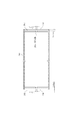
また、図2に本発明の第1の実施形態の無端ベルトの斜視透視図を、図3に、図2に示した無端ベルトの縦断面図をそれぞれ示す。なお、図2においてリブ部材2は閉ループ状の無端ベルトである転写ベルト9の内面9aに設けられているが、理解を容易にするため、実線で示しており、また、リブ部材2が接着固定される溝9a(図3参照)は省略している。また、図3においても、転写ベルト9のみを縦断面で描いている。
【0037】
画像形成装置1は、感光ドラム10と、感光ドラム10の表面を帯電させる帯電チャージ11と、感光ドラム10上に静電潜像を形成する露光装置である光書込装置12と、感光ドラム10の表面に供給されるトナー14を内部に保持する現像器13と、画像が形成される転写紙19を搬送する、ローラ15、16、17、18に張架された転写ベルト9と、シート材である転写紙19を転写ベルト9に吸着させる紙吸着帯電器20と、転写紙19上にトナー14を転写する転写帯電器と、転写紙19上に転写されたトナー14を定着させる定着ローラ22を含む定着装置22とを有する。
【0038】
転写ベルト9は、図3に示すにようにその内面9aに、幅方向端部30から距離Aの位置に、転写ベルト9の周方向に沿って溝9bが形成されており、この溝9bには、リブ部材2が接着固定されている。すなわち、距離Aは、リブ部材2の幅方向端部30側の端面であるリブ端面2dから転写ベルト9の幅方向端部30までの距離、換言すれば、溝9bの幅方向端部30側の溝壁9cまでの距離ということになる。このリブ部材2は、切れ目のないリング形状ではなく、断面形状が矩形である、1本の弾性部材を溝9bに接着固定したものであり、転写ベルト9の溝9bの周長と概ね同じ長さであるが、若干短いため溝9bに接着固定された状態でリブ部材2の第1の端部2bと第2の端部2cとの間には、間隔Xの間隙部2aが形成されることとなる。なお、上述の距離Aは、間隔Xの間隙部2aが形成されたリブ部材2を用いることによる転写ベルト9の間隙部2aの応力集中が転写ベルト9の幅方向端部30にかかることで、転写ベルト9が所望の耐用時間を達成する前に破断することのないような距離である。
【0039】
また、図4は、ローラ15、16、17、18に対して張架されている転写ベルト9を図1に示す矢印Fの方向から見た透視平面図である。ただし、帯電チャージャ11、感光ドラム10、および転写紙19は省略されている。ローラ15、17、18は互いの軸に対して平行に配置されているが、ローラ16は、ローラ15、17、18の軸に対して角度αだけ傾斜して設けられている。このようにローラ16を傾斜して配置することにより、図中上側の転写ベルト9の長さGは、下側の長さHよりも長くなり、転写ベルト9のG側の速度の方がH側よりも速くなり、よって、転写ベルト9は矢印Iの方向に寄せられていく。これによりリブ部材2がローラ15、17、18の側面に接触、すなわち、引っかかり、蛇行が抑制される。なお、傾斜して設けられるローラはローラ16に限定されるものではなく、何れのローラが傾斜されているものであってもよい。
【0040】
ローラ15、16、17、18に張架された転写ベルト9は、一定速度Vfで矢印bの方向に回転駆動される。
【0041】
以下に各部構成の機能および画像形成装置1による画像形成に関する概略を説明する。
【0042】
感光ドラム10は、不図示の駆動手段により矢印aの方向に一定速度Vfで回転駆動される。その表面は、まず、帯電チャージャ11により一様に帯電させられ、レーザ光を用いた光書込装置12により、静電潜像が形成される。この光書込装置12に反射光を使用しても差し支えない。現像器13中にはトナー14が収容されており、光書込装置12により形成された静電潜像部分に、電荷付与されたトナー14が付着し、トナー像として顕像化される。
【0043】
一方、転写紙19は、転写ベルト9上に給紙され、紙吸着帯電器20によって転写ベルト9に吸着させられ、矢印cで示す方向に搬送される。この時、転写紙19は転写ベルト9と同速度Vfで搬送される。転写紙19が転写領域31に達すると、感光ドラム10上に顕像化されたトナー14は、紙吸着帯電器20により転写紙19上に転写される。転写後、転写紙19は、さらに定着装置21にまで搬送される。この定着装置21は、加熱用回転体である定着ローラ22を加圧用回転体としての加圧ローラ23によって不図示のヒータ(加熱体)に密着させて摺動搬送し、この定着ローラ22と加圧ローラ23との間に構成される定着ニップ部にて、未定着トナー像を担持した転写紙19を定着ローラ22ともに挟持搬送し、定着ローラ22を介して付与されるヒータからの熱と定着ニップ部の加圧力とによって未定着トナー像を転写紙19の表面に永久画像として定着させる装置である。転写紙19は、このようにして定着装置22によりトナー14の定着がなされた後、外部に排出される。
【0044】
次に、転写ベルト9上にライン形状のリブ部材2を接着する詳細工程を図5を用いて説明する。なお、以下に説明する接着の工程の前に、転写ベルト9には、すでに幅方向端面30から転写ベルト9の内側方向に向けて距離Aの位置に溝壁9cが位置するように溝9bが形成されており、また、リブ部材2は矩形断面に成型されている。
【0045】
まず、転写ベルト9を図5(a)に示すような3軸のローラ3、4、5に張架する。ローラ3は駆動ローラであり、10mm/secの速度で転写ベルト9を回転移動させることができる。なお、このローラ3の回転速度は、10mm/secに限定されるものではない。各々のローラ3、4、5には、凹型の溝3’、4’、5’がローラ3、4、5の片端側に形成されている。溝3’、4’、5’は作成するベルトの形状に応じて任意にその位置、形状を設定することができる。
【0046】
次に、図5(a)をB方向からみた図である図5(b)に示すように、全長に渡って矩形断面形状を有し、この矩形断面の長辺方向、短辺方向共に所望の加工精度で作成されているリブ部材2を、転写ベルト9の端面から距離Aに、リブ部材2の外面を合わせるように取り付ける。またリブ部材2を取り付ける略直前に転写ベルト9の溝9bにエポキシ系の接着剤6を塗布しておく(図5(a)参照)。なお、リブ部材2の長辺方向、短辺方向の加工精度は±0.1mm以内であってもよいし、リブ部材2の取り付けの際の位置精度は全周にわたり±0.1mmになるように設定してもよいし、距離Aは2.0mmであってもよい。
【0047】
以上のように、接着剤6を溝9bに塗布してリブ部材2を取り付ける工程をベルト全周に渡り実施した後、余分なリブ部材2をカットする。カットする断面はリブ部材2の長手方向に対し略直角とした。図5(c)に示す、リブ部材2の取り付け始めの端部である第1の端部2bと、取り付け終了の端部である第2の端部2cとの間隔Xは、1.5mmであってもよい。なお、接着剤6が常温硬化型接着剤であってもよいし、時間短縮のため、加熱硬化型、紫外線硬化型等任意に用いるとさらに最適である。
【0048】
次に本実施形態に適用できるシート状フィルム材料について示す。
【0049】
本実施形態の転写ベルト9に使用可能な材料は、非熱可塑性樹脂、熱硬化性樹脂、熱可塑性樹脂材料、金属材料、無機材料、如何なる材料でも使用に好適であり、特に、樹脂を用いる場合には、各種非熱可塑性、熱硬化性ポリイミド、ポリエチレン、ポリプロピレン、ポリメチルペンテン−1、ポリスチレン、ポリアミド、ポリカーボネート、ポリサルフォン、ポリアリレート、ポリエチレンテレフタレート、ポリブチレンテレフタレート、ポリフェニレンサルファイド、ポエーテルサルフォン、ポリエーテルニトリル、熱可塑性ポリイミド系材料、ポリエーテルエーテルケトン、サーモトロピック液晶ポリマ、ポリアミド酸、各種フッ素樹脂等の全ての樹脂材料およびそのブレンド樹脂、また上記ブレンドで形成した熱可塑性エラストマーも使用にさらに好適である。
【0050】
また、上記樹脂材料に耐熱補強、導電性、熱伝導性付与等の目的で、有機、無機の微粉末の少なくとも1種を配合したフィルム、あるいはあらゆる倍率で延伸強化したフィルム等も使用しうる。
【0051】
ここで、有機の微粉末として、例えば縮合型ポリイミド粉末など、また無機微粉末としては、カーボンブラック粉末、酸化マグネシウム粉末、フッ化マグネシウム粉末、酸化ケイ素粉末、酸化アルミニウム粉末、窒化ホウ素粉末、窒化アルミニウム粉末、酸化チタン粉末等の無機球状微粒子、炭素繊維、ガラス繊維等の繊維状粒子や、チタン酸カリウム、炭化ケイ素、窒化ケイ素等のウィスカー状粉末等あらゆる形状、大きさの微粉末が使用しうる。
【0052】
また、これらの微粉末の配合量は、総合量でベース樹脂に対して、5〜70wt%にすることが好ましい。
【0053】
また本実施形態に適用できるリブ部材2の材料としては、例えばスチレンブタジエンゴム、ニトリルゴム、クロロプレンゴムエチレンプロピレンターポリマ、ブチルゴム、イソプレンゴム、シリコーンゴム等のゴム系やスチレン系、オレフィン系、ポリ塩化ビニル系、ウレタン系、ポリエステル系、ポリアミド系、ふっ素系、塩素化ポリエチレン系等の熱可塑性エラストマーが好適である。
【0054】
接着剤としてはネオプレン、クロロプレン等のゴム系接着剤、メラミン樹脂系、フェノール樹脂系、エポキシ系、酢ビ系、エチレンビニルアセテート系、シアノアクリレート系、ポリウレタン系等が好適である。
【0055】
なお、リブ部材2の硬度は、転写ベルト9の硬度よりも小さいほうが好適である。
【0056】
以上の工程により作成した、無端ベルトの片端部に蛇行防止用のリブを装着した転写ベルト9を、転写ベルト9として使用し、さらに転写ベルト9を張架しているローラ15、16、17、18のうち少なくとも1本を傾斜させ、本ベルト9のリブ部材2が必ずローラ15、16、17、18の端面に当接するように設定した。
【0057】
このようにリブ部材2を常にローラ15、16、17、18の側面に接触させることで、回転駆動時における転写ベルト9の蛇行が抑制されて、位置精度が高められ、非常に高精細の画像が得られることとなる。
【0058】
また、本実施形態の転写ベルト9の場合、リブ部材2を幅方向端部30から間隙部の距離Xよりも大きい距離Aだけ離してリブ部材2を取り付けているためリブ部材2の間隙部2aの応力集中が幅方向端部30にかからず内面9aにかかる。これにより、転写ベルト9を端部から引き裂くような力がかからず、転写ベルト9の耐久性を向上させることができる。
【0059】
(第2の実施形態)
次に、本発明の第2の実施形態の転写ベルトの斜視透視図を図6に示す。
【0060】
転写ベルト159は、両端側に、計2本のリブ部材152が取り付けられている。画像形成装置のローラに取り付ける場合、各リブ部材152の内側面をローラの側面に接触するように張架することで、回転駆動時における転写ベルト159の蛇行が抑制されることとなるため、張架するローラを傾斜させる必要はない。
【0061】
また、図6に示すような2本のリブ部材152を転写ベルト159に接着するには、図7に示すような、両端側に溝3a’、4a’、5a’が形成されているローラ3a、4a、5aを用いて行われるものであってもよい。
【0062】
以上説明した以外は、基本的に第1の実施形態と同様であるため詳細の説明は省略する。
【0063】
本実施形態も第1の実施形態と同様に、リブ部材152がローラの側面に接触することによって転写ベルト159の蛇行が抑制されて、位置精度が高められ、非常に高精細の画像が得られるとともに、リブ部材152の間隙部152aの応力集中が幅方向端部180にかからず内面159aにかかることで、転写ベルト159を端部から引き裂くような力がかからず、転写ベルト159の耐久性を向上させることができる。
【0064】
(第3の実施形態)
次に、図8に本発明の第3の実施形態の画像形成装置の模式図を示す。
【0065】
本実施形態の画像形成装置は、第1の像担持体として感光ドラム601を有し、この感光ドラム601は、図示しない駆動手段によって矢印方向に回転駆動され、その回転過程で感光ドラム601に当接した一次帯電ローラ611により表面が一様に帯電される。ついで、露光装置603により、マゼンタの画像模様に従ったレーザ光Lが感光ドラム601の表面に照射され、感光ドラム601の表面に静電潜像が形成される。
【0066】
回転支持体614に4個の現像器604a、604b、604c、604dが支持されており、回転支持体614の回転により、マゼンタトナーを収容した現像器604aが感光ドラム601と対向した位置(現像位置)に移動し、このように選択された現像器604aにより感光ドラム601上の潜像が現像される。
潜像は現像によりマゼンタトナー像として可視化される。
【0067】
第2の像担持体としてリブ部材602が取り付けられた中間転写ベルト605が設置されている。この中間転写ベルト605は、ローラ605a、605bおよび605cに張架されており、ローラ605a、605c間の1次転写ローラ606によって感光ドラム1と接触し、ローラ605aの駆動により感光ドラム601と略同速度で矢印方向に回転する。なお、中間転写ベルト605に対するリブ部材602は、基本的に第1の実施形態と同様にリブ部材602の端面間に形成される不図示の間隙部における応力集中が中間転写ベルト605の幅方向端面にかからないような位置に取り付けられている。
【0068】
なお、第1の実施形態と同様にローラ605a、605b、605cのいずれかを傾斜させて、リブ部材602がローラ605a、605b、605cの端面に接触、すなわち、引っかかるようにして、中間転写ベルト605の蛇行を抑制するものであってもよいし、第2の実施形態で示したように2本のリブ部材602を取り付けて蛇行を抑制するものであってもよい。
【0069】
感光ドラム601上に形成されたマゼンタトナー像は、1次転写ローラ606に印加した1次転写バイアスにより、中間転写ベルト605の表面に1次転写される。
【0070】
以上の行程をシアン、イエロー、ブラックの他の3色についても行うことにより、中間転写ベルト5上に4色のトナー像を重ね合わせて転写したカラー画像が形成される。
【0071】
転写紙609が所定のタイミングで中間転写ベルト5に供給される。これと同時に2次転写ローラ608に2次転写バイアスを印加するとともに、2次転写ローラ608により転写紙609を挟んで中間転写ベルト605に当接することにより、中間転写ベルト605上の4色のトナー像が転写紙609の表面に一括して2次転写される。
【0072】
このようにして4色のトナー像を転写された転写紙609は、搬送ベルト613によって定着装置609まで搬送され、そこで加熱および加圧によりトナーが転写紙609に溶融固定されてフルカラーの定着画像とされた後、画像形成装置本体外の排紙トレイに排出される。なお、定着装置609は定着ローラを備えたものであってもよい。
【0073】
4色のトナー像の転写が終了して、中間転写ベルト605の表面に残留した2次転写残りのトナーは、クリーニングローラ610により清掃される。一方、感光ドラム601上の1次転写残りのトナーは、ブレード手段を有する公知のクリーニング装置607により清掃される。
【0074】
本実施形態も第1および第2の実施形態と同様に、リブ部材602によって中間転写ベルト605の蛇行が抑制されて、位置精度が高められ、非常に高精細の画像が得られるとともに、リブ部材602の間隙部の応力集中が幅方向端部にかからず中間転写ベルト605の内面にかかることで、中間転写ベルト605を端部から引き裂くような力がかからず、中間転写ベルト605の耐久性を向上させることができる。
【0075】
(第4の実施形態)
次に、本発明の第4の実施形態の画像形成装置における定着装置の概略側面図を図9(a)に、また、図9(a)のJ−J線における定着ローラの一部拡大断面図を図9(b)にそれぞれ示す。なお、図9(b)では、ヒータは省略されている。
【0076】
定着装置721の定着フィルム722の内周には、リブ部材702が取り付けられている。リブ部材702の内側側面に、画像形成装置の側壁731から延びたフック730が接触、すなわち、引っかかるように構成されており、これによって、図9(b)中の矢印M方向への定着フィルム722が規制、すなわち、蛇行が抑制されるようになっている。このような定着フィルム722と加圧ローラ723とにより形成されたニップ部724にて、未定着トナー像を担持した転写紙719を定着フィルム722ともに挟持搬送し、定着フィルム722を介して付与されるヒータ710からの熱とニップ部724の加圧力とによって未定着トナー像を転写紙719の表面に永久画像として定着させるものとなっている。
【0077】
なお、定着フィルム722に対するリブ部材702の取り付け位置、リブ部材702の形状、及び素材等は、第1ないし第3の実施形態で説明したものと同様であるため、詳細の説明は省略する。また、本実施形態の画像形成装置の基本的構成は、第1および第2の実施形態で説明した画像形成装置と基本的に同様の構成となるため、詳細の説明は省略する。
【0078】
本実施形態も第1ないし第3の実施形態と同様に、リブ部材702によって定着フィルム722の蛇行が抑制されるとともに、リブ部材702の間隙部の応力集中が幅方向端部にかからず定着フィルム722の内面にかかることで、定着フィルム722を端部から引き裂くような力がかからず、定着フィルム722の耐久性を向上させることができる。
【0079】
なお、上述した各実施形態は組み合わせて用いられるものであってもよい。
【0080】
【実施例】
以下に図1に示した画像形成装置を用いての、本発明の無端ベルトの実施例を説明する。なお、本発明はこれらの例によって限定されるものではない。
【0081】
(第1の実施例)
図10に本発明の第1の実施例で用いた転写ベルトの縦断面図を示す。本実施例では、図10に示すような構造の転写ベルトを図1で示した画像形成装置に用いて、転写ベルトの耐久時間を測定した。
【0082】
転写ベルト9は厚さ150μmであり、材質として非熱可塑性のポリイミド樹脂(商品名:ユーピレックスS、宇部興産(株)製)を用い導電性カーボンブラック粒子を添加することにより体積抵抗値を10×1011Ω・cmに制御している。
【0083】
リブ部材102は、転写ベルト109の幅方向端面130とリブ端面102との距離が2.0mmとなる位置で、転写ベルト109の片端側に取り付けられている。また、リブ部材102の間隙部102aの間隔は、1.5mmである。リブ部材2の断面形状は4.0×1.5mmの長方形であり、長辺側を転写ベルト9に接着している。本実施例で使用した接着剤は、JIS A硬度80度のエポキシ系の弾性接着剤(商品名:EP-001、セメダイン(株)製)であり、特登録02862317号公報で明らかなようにベルトの駆動を考慮してJIS A硬度100度以下のモノを使用すると最適である。なお、リブ部材102は、JIS A硬度85度のEPDMゴム製であり導電性は付与していない。
【0084】
以上の通りの転写ベルト9を、図1に示す画像形成装置1としてレーザービームプリンター(商品名:LBP2360、キヤノン(株)製)を使用し、そのローラ15、16、17、18に取り付け、転写ベルト9の耐久試験を行った。なお、この際、ローラ16は傾斜して画像形成装置1に搭載されている。
【0085】
本実施例の転写ベルト109に取り付けられたリブ部材102の位置精度は非常に高く、かつ、均一であるため、高精細の画像が得られた。またリブ部材102の間隙部102aの応力集中もベルト内面に係るため、後述するような強度な端裂抵抗が発生し、それによる転写ベルト109の破れ等も300時間以上発生しなかった。
【0086】
(第2の実施例)
次に、本発明の第2の実施例で用いた転写ベルトを図11、図12に示す。図11は、転写ベルトの斜視透視図であり、図12は、転写ベルトに対するリブ部材の取り付け位置を説明するための縦断面図である。
【0087】
本実施例では、転写ベルト209の両端側にリブ部材202が取り付けられた転写ベルト209を用いた。転写ベルト209の幅方向端部230からリブ部材202の端面までの距離Aは、2.0mmで、間隙部202aの距離Xは1.5mmである。これら距離Aおよび距離Xは、左右のリブ部材202とも同じである。
【0088】
転写ベルト209の厚さおよび体積抵抗値は、それぞれ150μm、10×1011Ω・cmで、第1の実施例と同様であるが、材質はポリフッ化ビニリデン樹脂(商品名:KFポリマー、呉羽化学工業(株)製)である。
【0089】
リブ部材202の寸法、および接着剤の材質、またリブ部材202を転写ベルト209上に取り付ける方法は第1の実施例と同様である。ただし、リブ部材202を転写ベルト209上に取り付ける際に用いたローラは、図7で示したタイプのものを用いた。
【0090】
以上のような転写ベルト209を、ローラ16を傾斜させていない以外は基本的に同様の構成である第1の実施例で用いた画像形成装置のローラ15、16、17、18に張架し、転写ベルト209の耐久試験を行ったところ、本実施例においても、高精細の画像が得られたとともに、転写ベルト209の破れ等も300時間以上発生しなかった。
【0091】
(第3の実施例)
次に、図13に、本発明の第3の実施例で用いた転写ベルトの縦断面図を示す。
【0092】
本実施例も第2の実施例と同様に、転写ベルト309には2本のリブ部材302が取り付けられているが、転写ベルト309の幅方向端部330からリブ部材302の端面までの距離が、第2の実施例では2.0mmであったのに対し、本実施例では5.0mmであり、第2の実施例よりもさらに内側にリブ部材302が取り付けられている。なお、リブ部材202の寸法、間隙部302aの距離、および接着剤の材質、またリブ部材202を転写ベルト209上に取り付ける方法は第1および第2の実施例と同様である。
【0093】
以上のような転写ベルト309を、第2の実施例で用いた、ローラ16を傾斜させていない画像形成装置のローラに張架し、転写ベルト309の耐久試験を行ったところ、本実施例においても、高精細の画像が得られたとともに、転写ベルト309の破れ等も700時間以上発生しなかった。
【0094】
(比較例1)
次に、図14に、第1ないし第3の実施例に対して比較するための転写ベルトの縦断面図を示す。
【0095】
本比較例は、転写ベルト409の幅方向端部430からリブ部材402の端面までの距離が、0.5mmである以外は、第2および第3の実施例と全て同様であるため、詳細の説明は省略する。
【0096】
以上のような転写ベルト409を、第2および第3の実施例で用いた、ローラ16を傾斜させていない画像形成装置のローラに張架し、転写ベルト409の耐久試験を行ったところ、50時間で転写ベルト409のリブ部材402の間隙部402aから生じた亀裂が確認された。
【0097】
(第4の実施例)
第2の実施例において、第1の距離(A)と第2の距離(X)をそれぞれ、3.0mm、1.5mmとしたことを除いて、同様の方法で転写ベルトを製造し、第2の実施例と同様の画像形成装置で耐久試験を行ったところ、500時間以上の耐久性が認められた。
【0098】
(第5の実施例)
第2の実施例において、第1の距離(A)と第2の距離(X)をそれぞれ、3.0mm、1.0mmとしたことを除いて、同様の方法で転写ベルトを製造し、第2の実施例と同様の画像形成装置で耐久試験を行ったところ、700時間以上の耐久性が認められた。
【0099】
(第6の実施例)
第2の実施例において、第1の距離(A)と第2の距離(X)をそれぞれ、1.6mm、1.5mmとしたことを除いて、同様の方法で転写ベルトを製造し、第2の実施例と同様の画像形成装置で耐久試験を行ったところ、100時間以上の耐久性が認められた。
【0100】
以上の第1ないし第6の実施例および比較例の、条件および測定結果を表1にまとめる。
【0101】
【表1】

耐久時間は、各10本の転写ベルトについて評価し、最も早く亀裂を生じた時間を下限値とした。
【0103】
ここで、以上のように転写ベルトの端面からある程度離れた位置にリブ部材を装着することにより耐久性が向上する原因について考察した。
【0104】
表2は、ポリフッ化ビニリデン樹脂の端裂抵抗強度(引き裂きを開始するときの強度)と引き裂き強度(引き裂きを伝えるのに要する強度)を測定した結果を示している。
【0105】
【表2】
なお、測定方法はJIS K7128法に準拠し、端裂抵抗強度としてC法(直角形引き裂き強度)、引き裂き強度としてA法(トラウザー引き裂き法)を用いた。
【0107】
これによると端裂抵抗強度は引き裂き強度より4・5倍の強度を保有している。
【0108】
すなわち、比較例のように転写ベルト409の幅方向端面430のぎりぎりにリブ部材402を接着した場合、リブ部材402の間隙部の応力集中が転写ベルト409の幅方向端面430にかかることになる。幅方向端面430をいくら鋭利な刃物でカットして形成したとしても、そのカット面はミクロに見ればある程度荒れていることが予想される。つまり、幅方向端面430のぎりぎりにリブ部材402を取り付けた場合の挙動は、転写ベルト409の引き裂きに似ていると考えられる。そのため、少しの応力がリブ部材402の間隙部402aに集中し、転写ベルト409の破壊が生じたと考えられる。
【0109】
それに対し、第1ないし第6の実施例のように、リブ部材を転写ベルトの幅方向端面から離して取り付けた場合の挙動は、まず転写ベルトの連続面を引き裂く挙動に似ている。すなわち、端裂抵抗的な挙動を示す。そのため、転写ベルトに応力がかかっても、破れ等の不良は発生しにくかったと考察できる。
【0110】
【発明の効果】
以上のように本発明によれば、リブ部材の間隙部で無端ベルトに生じた応力集中の影響が無端ベルトの幅方向端面に及ばない位置にリブ部材が形成されているため、間隙部で無端ベルトに生じた応力集中によって、無端ベルトが間隙部近傍の幅方向端面から破断してしまうことを長時間抑制することができる。また、この無端ベルトは、1本のライン形状のリブ部材をローラに接触させながら駆動されるため、蛇行が抑制される。
【図面の簡単な説明】
【図1】本発明の第1の実施形態の画像形成装置の模式図である。
【図2】本発明の第1の実施形態の転写ベルトの斜視透視図である。
【図3】図2に示した本発明の第1の実施形態の転写ベルトの縦断面図である。
【図4】図1に示した転写ベルト部の透視平面図である。
【図5】本発明の第1の実施形態の転写ベルトにリブ部材を接着する工程を説明する図である。
【図6】本発明の第2の実施形態の転写ベルトの斜視透視図である。
【図7】転写ベルトに2本のリブ部材を接着するための、2本の溝が形成されているローラの断面図である。
【図8】本発明の第2の実施形態の画像形成装置の模式図である。
【図9】本発明の第3の実施形態の画像形成装置における定着装置の概略図である。
【図10】本発明の第1の実施例で用いた転写ベルトの各部寸法を示す縦断面図である。
【図11】本発明の第2の実施例で用いた転写ベルトの縦断面図である。
【図12】図11に示した転写ベルトの各部寸法を示す縦断面図である。
【図13】本発明の第3の実施例で用いた転写ベルトの各部寸法を示す縦断面図である。
【図14】比較のために用いた転写ベルトの各部寸法を示す縦断面図である。
【符号の説明】
1 画像形成装置
2、102、152、202、302、402、602、702 リブ部材
2a、102a、152a、202a、302a、402a 間隙部
2b 第1の端部
2c 第2の端部
3、4、5、3’、4’、5’、15、16、17、18、605a、605b、605c、605d ローラ
3’、4’、5’、3a’、4a’、5a’ 溝
6 接着剤
9、109、159、209、309、409 転写ベルト
9a、159a 内面
10、601 感光ドラム
11 帯電チャージャ
12 光書込装置
13、604a、604b、604c、604d 現像器
14 トナー
19、609、719 転写紙
20 紙吸着帯電器
21、621、721 定着装置
22、722 定着ローラ、定着フィルム
23、723 加圧ローラ
30、130、180、230、330、430 幅方向端部
31 転写領域
603 露光装置
605 中間転写ベルト
606 1次転写ローラ
607 クリーニング装置
608 2次転写ローラ
610 クリーニングローラ
611 帯電ローラ
613 搬送ベルト
614 回転支持体
710 ヒータ
724 ニップ部
730 フック
731 側壁[0001]
BACKGROUND OF THE INVENTION
The present inventionIs used as a functional component of image forming devices.Endless beltUsedThe present invention relates to a conveyance device and an image forming apparatus.
[0002]
[Prior art]
Conventionally, an image forming apparatus using an electrophotographic system forms an optical information electrostatic latent image on the surface of a photoconductor by running (rotating / moving) the photoconductor at a constant speed in one direction and exposing optical information. To do. As the photoreceptor, a type in which a cylindrical drum is rotated is common, but there is also a type in which an endless belt is run.
[0003]
In particular, when a color image is latent in an image forming apparatus using an electrophotographic system, a latent image of four colors Y (yellow), C (cyan), M (magenta), and K (black) is recorded. There is a method in which an endless belt conveyance device is used for a transfer material conveyance body, an intermediate transfer body, a continuous paper conveyance body and the like for mixing colors with a medium.
[0004]
Conventionally, as a fixing method for fixing and solidifying a toner latent image on a recording medium, a heat roller fixing method in which the recording medium is nipped and conveyed by a heat roller and a pressure roller has been widely used, but the warm-up time is shortened. Therefore, a fixing device using a thin endless endless belt is disclosed in Japanese Patent Laid-Open No. 63-313182.
[0005]
In recent years, there are many image forming apparatuses using endless belts. When a cylindrical drum is used in each of the above members, there was no problem by rotating the drum around the central axis of the drum as a rotation axis. The endless belt has a meandering problem with respect to the driving direction. If the meandering is left as it is, a desired image cannot be formed (latent image, transfer, fixing), and a problem such as image distortion may occur.
[0006]
There are roughly two types of methods for preventing these endless belts from meandering.
[0007]
(1) There is a method of detecting an endless belt shift or meandering by some means, and forcibly returning the belt to the original running position by belt tension or centripetal force. This can be done by tilting the roller that drives the belt or the driven roller that is stretched so that it moves in the direction opposite to the direction of movement of the belt, or by stretching the belt between the drive roller and the driven roller. A swingable swinging roller that is in contact with the inner surface of the belt is provided at a substantially intermediate portion of the belt, and the swinging roller is moved in either direction in accordance with a signal from a detecting means that detects a deviation of the belt disposed on both ends of the belt. A method of swinging is disclosed in Japanese Patent Laid-Open No. 54-69442.
[0008]
However, each of the above methods requires the use of detection means, and a mechanical device for inclining the roller and an extra member such as a vibration roller that is substantially unnecessary for the image forming apparatus are required. In terms of cost, the configuration becomes expensive.
[0009]
On the other hand, as a method to prevent meandering of the endless belt at a low cost
(2) An endless or endless rib member with a rubber band is attached to one or both ends of the front or back surface of the endless belt, and the rib member is driven and driven. A method of restricting meandering by abutting against a guide portion provided in a part is considered. As a method of mounting the rib member on the inner surface of the endless belt, Japanese Patent Laid-Open No. Hei 4-159911 etc., as a method of mounting the rib member on the outer side of the endless belt,JP-A-3-25477 (Japanese Patent Application No. 1-160277)Etc. have already been proposed.
[0010]
[Problems to be solved by the invention]
However, in the method of controlling meandering by attaching a rib member such as rubber to at least one end of the endless belt end of the above (2) and regulating it with a guide member, in recent years, color image formation described later Since problems such as color misalignment occur at times, it is necessary to attach ribs with extremely high accuracy, and accordingly, accuracy of shape such as straightness and linearity of the rib member itself is required. Has been. For this reason, as a rib member to be used, a case where a line-shaped rib member whose shape is easily controlled with higher precision than an endless rubber band rib member is increasing.
[0011]
However, when an endless rib member is used, there is no particular problem. However, when a line-shaped rib member is used, a slight gap is formed at the joint portion formed by both ends of the rib member. In this state, when the endless belt is stretched around the roller and driven, the stress generated from the discontinuity of the rib member is applied to the belt portion located in the gap of the rib member every time the gap passes through the roller portion. The load is repeatedly received from other parts. For this reason, the belt is liable to break or break from the joint.
[0012]
As a means for preventing this, a method has been devised in which the stress concentration is dispersed by cutting the shape of the end face of the rib member of the joint diagonally or by devising the shape of the rib end face as a key shape. . However, at present, there are many problems such as devices on the device for cutting diagonally or into a key shape and bonding accuracy.
[0013]
Accordingly, the present invention provides an endless belt having high durability and suppressing meandering.UsedIt is an object of the present invention to provide a conveyance device and an image forming apparatus.
[0014]
[Means for Solving the Problems]
According to the present inventionAn endless belt is an endless belt in which one line-shaped rib member is bonded and fixed to one end of the back surface along the circumferential direction, and the rib member is bonded and fixed with a gap at the joint. And the distance between the end face on the side close to the rib member of the two end faces in the width direction of the endless belt and the rib member is longer than the gap. Glued and fixedThe
[0015]
The endless belt of the present invention configured as described above has a rib member formed at a position where the influence of stress concentration generated in the endless belt does not reach the end surface in the width direction of the endless belt. It can be prevented for a long time that the endless belt breaks from the end surface in the width direction near the gap due to the stress concentration generated in the endless belt at the portion.
[0016]
Of the two end faces in the width direction of the endless belt, the distance between the end face close to the rib member and the rib member is:It is longer than the interval of the interval part, particularly preferably twice or more.
[0017]
The cross-sectional shape of the rib member may be rectangular or the hardness of the rib member may be smaller than the hardness of the endless belt.
[0022]
The conveying device of the present invention includes a conveying belt stretched between at least two rollers,TheDrive means for driving at least one of the rollersRuIn the transport device for transporting the sheet material, the transport belt is the endless belt described above.And the conveyor belt is stretched so that the inner surface of the rib member contacts the side surface of the roller.It is characterized by that.
[0023]
Since the conveying device of the present invention configured as described above uses the endless belt of the present invention as the conveying belt, the conveying belt starts from the end surface in the width direction near the gap due to the stress concentration generated in the conveying belt at the gap. Breaking is prevented for a long time.
[0024]
In the tubular film of the present invention, at least one rib member whose both end surfaces are opposed to each other is provided on the inner peripheral surface, and the tubular film is rotated while contacting the rib member with an external regulating member.
A first distance that is a distance from a width direction end face that is an end face in the width direction of the tubular film close to the side where the rib member is provided, to a side face of the rib member that is close to the width direction end face, The rib member is longer than a second distance that is an interval of a gap formed by facing each end face of the rib member.
[0025]
In the tubular film of the present invention configured as described above, the rib member is formed at a position where the influence of the stress concentration generated in the tubular film in the gap portion of the rib member does not reach the end surface in the width direction of the tubular film. It can be prevented for a long time that the tubular film breaks from the end surface in the width direction near the gap due to the stress concentration generated in the tubular film at the portion.
[0026]
The first distance is longer than the second distance, which is the interval between the interval portions, and more preferably twice or more. Moreover, the cross-sectional shape of the rib member may be rectangular, or the rib member may have a hardness smaller than that of the tubular film.
[0029]
The image forming apparatus of the present invention forms a latent image on the surface of the charged photosensitive drum, attaches toner to the latent image,Stretched between at least two rollersIn an electrophotographic image forming apparatus in which the toner is transferred to a transfer material conveyed by a conveyance belt and fixed by a fixing device, the conveyance belt is the endless belt described above.And the conveyor belt is stretched so that the inner surface of the rib member is in contact with the side surface of the roller.It is characterized by that.
The image forming apparatus of the present invention forms a latent image on the surface of a charged photosensitive drum, attaches toner to the latent image, and then applies the toner., Stretched between at least two rollersIn an image forming apparatus that performs primary transfer to an intermediate transfer belt and secondarily transfers toner that has been primarily transferred to the intermediate transfer belt to a transfer material, the intermediate transfer belt is the endless belt described above.And the intermediate transfer belt is stretched so that the inner surface of the rib member is in contact with the side surface of the roller.It is characterized by that.
[0030]
Since the image forming apparatus of the present invention configured as described above uses the endless belt of the present invention as the conveying belt, the end surface in the width direction near the gap due to the stress concentration generated in the conveying belt at the gap of the conveying belt. From being broken for a long time.
[0032]
DETAILED DESCRIPTION OF THE INVENTION
In an endless belt which is stretched between at least two rollers provided on the inner peripheral surface with at least one rib member facing both end surfaces, and is driven while the rib member is in contact with the side surface of the roller. The ribElementThe first distance, which is the distance from the width direction end surface, which is the end surface in the width direction of the endless belt, near the side where the end member is provided, to the side surface of the rib member on the side close to the width direction end surface is 10 mm or less. Is preferred. That is, the first distance is a meaningless space for image formation, and is preferably smaller in terms of the apparatus configuration.
[0033]
Moreover, 1-5 mm is suitable for the 2nd distance which is the space | interval of the gap | interval part formed when each end surface of a rib member opposes. That is, stress concentrates on the endless belt portion at the interval between the end faces of the rib members at the roller stretching position. The magnitude of this stress increases as the facing distance decreases, and if it increases, the possibility that a crack will occur in the belt portion increases. Therefore, the second distance is preferably 1 mm or more. Further, in setting the first distance to a preferable value of 10 mm or less, the second distance is preferably 5 mm or less.
[0034]
Next, embodiments of the present invention will be described with reference to the drawings.
[0035]
(First embodiment)
FIG. 1 is a schematic diagram of an image forming apparatus according to a first embodiment of the present invention.
[0036]
2 is a perspective perspective view of the endless belt according to the first embodiment of the present invention, and FIG. 3 is a longitudinal sectional view of the endless belt shown in FIG. In FIG. 2, the
[0037]
The image forming apparatus 1 includes a photosensitive drum 10, a charging charge 11 that charges the surface of the photosensitive drum 10, an optical writing device 12 that is an exposure device that forms an electrostatic latent image on the photosensitive drum 10, and the photosensitive drum 10. A developing unit 13 that holds
[0038]
As shown in FIG. 3, a groove 9b is formed on the
[0039]
4 is a perspective plan view of the
[0040]
The
[0041]
Hereinafter, functions of each component and an outline of image formation by the image forming apparatus 1 will be described.
[0042]
The photosensitive drum 10 is rotationally driven at a constant speed Vf in the direction of arrow a by a driving unit (not shown). The surface is first uniformly charged by the charging charger 11, and an electrostatic latent image is formed by the optical writing device 12 using laser light. The optical writing device 12 may use reflected light. A
[0043]
On the other hand, the transfer paper 19 is fed onto the
[0044]
Next, a detailed process for bonding the line-shaped
[0045]
First, the
[0046]
Next, as shown in FIG. 5B, which is a view of FIG. 5A viewed from the B direction, it has a rectangular cross-sectional shape over the entire length, and both the long side direction and the short side direction of this rectangular cross section are desired. The
[0047]
As described above, after the step of applying the adhesive 6 to the groove 9b and attaching the
[0048]
Next, the sheet-like film material applicable to this embodiment is shown.
[0049]
The material that can be used for the
[0050]
In addition, a film in which at least one of organic and inorganic fine powders is blended with the above resin material for the purpose of heat resistance reinforcement, conductivity, and thermal conductivity, or a film that is stretch-strengthened at any magnification can be used.
[0051]
Here, as organic fine powder, for example, condensation type polyimide powder, etc., and as inorganic fine powder, carbon black powder, magnesium oxide powder, magnesium fluoride powder, silicon oxide powder, aluminum oxide powder, boron nitride powder, aluminum nitride Fine powders of all shapes and sizes can be used, such as powders, inorganic spherical fine particles such as titanium oxide powder, fibrous particles such as carbon fibers and glass fibers, whisker-like powders such as potassium titanate, silicon carbide, and silicon nitride. .
[0052]
Moreover, it is preferable that the compounding quantity of these fine powders shall be 5-70 wt% with respect to base resin in a total amount.
[0053]
Examples of the material of the
[0054]
Suitable adhesives are rubber adhesives such as neoprene and chloroprene, melamine resin, phenol resin, epoxy, vinyl acetate, ethylene vinyl acetate, cyanoacrylate, polyurethane and the like.
[0055]
The hardness of the
[0056]
The
[0057]
As described above, the
[0058]
Further, in the case of the
[0059]
(Second Embodiment)
Next, FIG. 6 shows a perspective perspective view of a transfer belt according to a second embodiment of the present invention.
[0060]
A total of two
[0061]
Further, in order to bond the two
[0062]
Except for what has been described above, the configuration is basically the same as that of the first embodiment, and a detailed description thereof will be omitted.
[0063]
Similarly to the first embodiment, this embodiment also suppresses meandering of the transfer belt 159 by the
[0064]
(Third embodiment)
Next, FIG. 8 shows a schematic diagram of an image forming apparatus according to a third embodiment of the present invention.
[0065]
The image forming apparatus of the present embodiment has a photosensitive drum 601 as a first image carrier, and this photosensitive drum 601 is rotationally driven in the direction of an arrow by a driving unit (not shown), and contacts the photosensitive drum 601 in the rotation process. The surface is uniformly charged by the
[0066]
Four developing
The latent image is visualized as a magenta toner image by development.
[0067]
An intermediate transfer belt 605 to which a rib member 602 is attached is installed as a second image carrier. The intermediate transfer belt 605 is stretched around
[0068]
As in the first embodiment, one of the
[0069]
The magenta toner image formed on the photosensitive drum 601 is primarily transferred onto the surface of the intermediate transfer belt 605 by the primary transfer bias applied to the primary transfer roller 606.
[0070]
By performing the above process for the other three colors, cyan, yellow, and black, a color image is formed by superimposing and transferring the four color toner images on the intermediate transfer belt 5.
[0071]
The
[0072]
The
[0073]
After the transfer of the four color toner images, the remaining secondary transfer toner remaining on the surface of the intermediate transfer belt 605 is cleaned by the cleaning roller 610. On the other hand, the primary transfer remaining toner on the photosensitive drum 601 is cleaned by a known
[0074]
Similarly to the first and second embodiments, in this embodiment, meandering of the intermediate transfer belt 605 is suppressed by the rib member 602, the positional accuracy is improved, and a very high-definition image is obtained. Since the stress concentration in the gap portion 602 is not applied to the end portion in the width direction but is applied to the inner surface of the intermediate transfer belt 605, a force that tears the intermediate transfer belt 605 from the end portion is not applied, and the durability of the intermediate transfer belt 605 is improved. Can be improved.
[0075]
(Fourth embodiment)
Next, a schematic side view of the fixing device in the image forming apparatus of the fourth embodiment of the present invention is shown in FIG. 9A, and a partially enlarged cross section of the fixing roller taken along line JJ in FIG. 9A. The figure is shown in FIG. In FIG. 9B, the heater is omitted.
[0076]
A
[0077]
Note that the mounting position of the
[0078]
Similarly to the first to third embodiments, in this embodiment, meandering of the fixing film 722 is suppressed by the
[0079]
In addition, each embodiment mentioned above may be used in combination.
[0080]
【Example】
An embodiment of the endless belt of the present invention using the image forming apparatus shown in FIG. 1 will be described below. Note that the present invention is not limited to these examples.
[0081]
(First embodiment)
FIG. 10 is a longitudinal sectional view of the transfer belt used in the first embodiment of the present invention. In this example, the transfer belt having the structure shown in FIG. 10 was used in the image forming apparatus shown in FIG. 1, and the durability of the transfer belt was measured.
[0082]
The
[0083]
The
[0084]
The
[0085]
Since the positional accuracy of the
[0086]
(Second embodiment)
Next, the transfer belt used in the second embodiment of the present invention is shown in FIGS. FIG. 11 is a perspective perspective view of the transfer belt, and FIG. 12 is a longitudinal sectional view for explaining the attachment position of the rib member to the transfer belt.
[0087]
In this embodiment, the transfer belt 209 in which the
[0088]
The thickness and volume resistance of the transfer belt 209 are 150 μm and 10 × 10 respectively.11Ω · cm, which is the same as that of the first example, but the material is polyvinylidene fluoride resin (trade name: KF polymer, manufactured by Kureha Chemical Industry Co., Ltd.).
[0089]
The dimensions of the
[0090]
The transfer belt 209 as described above is stretched around the
[0091]
(Third embodiment)
Next, FIG. 13 shows a longitudinal sectional view of the transfer belt used in the third embodiment of the present invention.
[0092]
In this embodiment, similarly to the second embodiment, two
[0093]
When the transfer belt 309 as described above was stretched over the roller of the image forming apparatus used in the second embodiment and in which the
[0094]
(Comparative Example 1)
Next, FIG. 14 shows a longitudinal sectional view of a transfer belt for comparison with the first to third embodiments.
[0095]
This comparative example is the same as the second and third embodiments except that the distance from the
[0096]
When the transfer belt 409 as described above was stretched on the roller of the image forming apparatus used in the second and third embodiments and in which the
[0097]
(Fourth embodiment)
In the second embodiment, a transfer belt is manufactured in the same manner except that the first distance (A) and the second distance (X) are 3.0 mm and 1.5 mm, respectively. When an endurance test was performed using the same image forming apparatus as in Example 2, durability of 500 hours or more was observed.
[0098]
(Fifth embodiment)
In the second embodiment, a transfer belt is manufactured by the same method except that the first distance (A) and the second distance (X) are 3.0 mm and 1.0 mm, respectively. When an endurance test was performed with the same image forming apparatus as in Example 2, durability of 700 hours or more was observed.
[0099]
(Sixth embodiment)
In the second embodiment, a transfer belt is manufactured in the same manner except that the first distance (A) and the second distance (X) are 1.6 mm and 1.5 mm, respectively. When an endurance test was performed using the same image forming apparatus as in Example 2, durability of 100 hours or more was observed.
[0100]
Table 1 summarizes the conditions and measurement results of the above first to sixth examples and comparative examples.
[0101]
[Table 1]
The durability time was evaluated for each of 10 transfer belts, and the earliest time at which cracking occurred was defined as the lower limit value.
[0103]
Here, the reason why the durability is improved by mounting the rib member at a position somewhat away from the end face of the transfer belt as described above was considered.
[0104]
Table 2 shows the results of measuring the end tear resistance strength (strength at the start of tearing) and tear strength (strength required to transmit tear) of the polyvinylidene fluoride resin.
[0105]
[Table 2]
In addition, the measuring method was based on JIS K7128 method, C method (right-angled tear strength) was used as end tear resistance strength, and A method (trouser tear method) was used as tear strength.
[0107]
According to this, the end tear resistance strength is 4.5 times as strong as the tear strength.
[0108]
That is, when the
[0109]
On the other hand, the behavior when the rib member is mounted apart from the end surface in the width direction of the transfer belt as in the first to sixth embodiments is similar to the behavior of first tearing the continuous surface of the transfer belt. That is, it exhibits a resistance to end tearing. Therefore, it can be considered that even if the transfer belt is stressed, it is difficult for defects such as tearing to occur.
[0110]
【Effect of the invention】
As described above, according to the present invention, the rib member is formed at a position where the influence of the stress concentration generated in the endless belt in the gap portion of the rib member does not reach the end surface in the width direction of the endless belt. It can be prevented for a long time that the endless belt breaks from the end face in the width direction near the gap due to the stress concentration generated in the belt. Further, since the endless belt is driven while a single line-shaped rib member is in contact with the roller, meandering is suppressed.
[Brief description of the drawings]
FIG. 1 is a schematic diagram of an image forming apparatus according to a first embodiment of the present invention.
FIG. 2 is a perspective perspective view of a transfer belt according to a first embodiment of the present invention.
3 is a longitudinal sectional view of the transfer belt according to the first embodiment of the present invention shown in FIG.
4 is a perspective plan view of a transfer belt portion shown in FIG. 1. FIG.
FIG. 5 is a diagram illustrating a process of bonding a rib member to the transfer belt according to the first embodiment of the present invention.
FIG. 6 is a perspective perspective view of a transfer belt according to a second embodiment of the present invention.
FIG. 7 is a cross-sectional view of a roller in which two grooves are formed for bonding two rib members to a transfer belt.
FIG. 8 is a schematic diagram of an image forming apparatus according to a second embodiment of the present invention.
FIG. 9 is a schematic diagram of a fixing device in an image forming apparatus according to a third embodiment of the present invention.
FIG. 10 is a longitudinal sectional view showing the dimensions of each part of the transfer belt used in the first embodiment of the present invention.
FIG. 11 is a longitudinal sectional view of a transfer belt used in a second embodiment of the present invention.
12 is a longitudinal sectional view showing dimensions of each part of the transfer belt shown in FIG.
FIG. 13 is a longitudinal sectional view showing dimensions of each part of a transfer belt used in a third embodiment of the present invention.
FIG. 14 is a longitudinal sectional view showing dimensions of each part of a transfer belt used for comparison.
[Explanation of symbols]
1 Image forming device
2, 102, 152, 202, 302, 402, 602, 702 Rib member
2a, 102a, 152a, 202a, 302a, 402a Gap
2b first end
2c second end
3, 4, 5, 3 ', 4', 5 ', 15, 16, 17, 18, 605a, 605b, 605c, 605d roller
3 ', 4', 5 ', 3a', 4a ', 5a' groove
6 Adhesive
9, 109, 159, 209, 309, 409 Transfer belt
9a, 159a inner surface
10, 601 Photosensitive drum
11 Charger charger
12 Optical writing device
13, 604a, 604b, 604c, 604d Developer
14 Toner
19,609,719 Transfer paper
20 Paper adsorption charger
21,621,721 Fixing device
22, 722 Fixing roller, fixing film
23,723 Pressure roller
30, 130, 180, 230, 330, 430 Width direction end
31 Transcription area
603 Exposure apparatus
605 Intermediate transfer belt
606 Primary transfer roller
607 Cleaning device
608 Secondary transfer roller
610 Cleaning roller
611 Charging roller
613 Conveyor belt
614 Rotating support
710 Heater
724 Nip part
730 hook
731 Side wall
Claims (3)
該搬送ベルトが無端ベルトであり、
該無端ベルトは、1本のライン形状のリブ部材が裏面の片端に周方向に沿って接着固定されており、該リブ部材は、その繋ぎ目に間隙を有して接着固定されており、かつ、該無端ベルトの幅方向の2つの端面のうちの該リブ部材に近い側の端面と、該リブ部材との間の距離が、該間隙の間隔よりも長くなるような位置に接着固定されており、
かつ、該搬送ベルトは該リブ部材の内側面が該ローラの側面に接触するように張架されていることを特徴とする搬送装置。In a conveying apparatus that conveys a sheet material having a conveying belt stretched between at least two rollers and a driving unit that drives at least one of the rollers,
Conveying belt is an endless belt,
The endless belt has one line-shaped rib member bonded and fixed to one end of the back surface along the circumferential direction, and the rib member is bonded and fixed with a gap at the joint; and The end face of the endless belt in the width direction is bonded and fixed at a position where the distance between the end face close to the rib member and the rib member is longer than the gap interval. And
And conveying belt conveying apparatus characterized by inner surfaces of said rib member is stretched so as to be in contact with the side surface of the roller.
該搬送ベルトが無端ベルトであり、
該無端ベルトは、1本のライン形状のリブ部材が裏面の片端に周方向に沿って接着固定されており、該リブ部材は、その繋ぎ目に間隙を有して接着固定されており、かつ、該無端ベルトの幅方向の2つの端面のうちの該リブ部材に近い側の端面と、該リブ部材との間の距離が、該間隙の間隔よりも長くなるような位置に接着固定されており、
かつ、該搬送ベルトは該リブ部材の内側面が該ローラの側面に接触するように張架されていることを特徴とする画像形成装置。A latent image is formed on the surface of the charged photosensitive drum, the toner is attached to the latent image, and then the toner is transferred to a transfer material conveyed by a conveyance belt stretched between at least two rollers. In an electrophotographic image forming apparatus to be fixed by a fixing device,
Conveying belt is an endless belt,
The endless belt has one line-shaped rib member bonded and fixed to one end of the back surface along the circumferential direction, and the rib member is bonded and fixed with a gap at the joint; and The end face of the endless belt in the width direction is bonded and fixed at a position where the distance between the end face close to the rib member and the rib member is longer than the gap interval. And
And conveying belt of the image forming apparatus characterized by inner surfaces of said rib member is stretched so as to be in contact with the side surface of the roller.
該中間転写ベルトが無端ベルトであり、
該無端ベルトは、1本のライン形状のリブ部材が裏面の片端に周方向に沿って接着固定されており、該リブ部材は、その繋ぎ目に間隙を有して接着固定されており、かつ、該無端ベルトの幅方向の2つの端面のうちの該リブ部材に近い側の端面と、該リブ部材との間の距離が、該間隙の間隔よりも長くなるような位置に接着固定されており、
かつ、該中間転写ベルトは該リブ部材の内側面が該ローラの側面に接触するように張架されていることを特徴とする画像形成装置。A latent image is formed on the surface of the charged photosensitive drum, and toner is attached to the latent image, and then the toner is primarily transferred onto an intermediate transfer belt stretched between at least two rollers, In an image forming apparatus that secondarily transfers toner that has been primarily transferred to an intermediate transfer belt to a transfer material,
Intermediate transfer belt is an endless belt,
The endless belt has one line-shaped rib member bonded and fixed to one end of the back surface along the circumferential direction, and the rib member is bonded and fixed with a gap at the joint; and The end face of the endless belt in the width direction is bonded and fixed at a position where the distance between the end face close to the rib member and the rib member is longer than the gap interval. And
And the intermediate transfer belt An image forming apparatus characterized by inner surfaces of said rib member is stretched so as to be in contact with the side surface of the roller.
Priority Applications (1)
| Application Number | Priority Date | Filing Date | Title |
|---|---|---|---|
| JP2001155611A JP5201772B2 (en) | 2000-05-26 | 2001-05-24 | Conveying apparatus and image forming apparatus |
Applications Claiming Priority (4)
| Application Number | Priority Date | Filing Date | Title |
|---|---|---|---|
| JP2000156649 | 2000-05-26 | ||
| JP2000-156649 | 2000-05-26 | ||
| JP2000156649 | 2000-05-26 | ||
| JP2001155611A JP5201772B2 (en) | 2000-05-26 | 2001-05-24 | Conveying apparatus and image forming apparatus |
Publications (3)
| Publication Number | Publication Date |
|---|---|
| JP2002080115A JP2002080115A (en) | 2002-03-19 |
| JP2002080115A5 JP2002080115A5 (en) | 2008-06-19 |
| JP5201772B2 true JP5201772B2 (en) | 2013-06-05 |
Family
ID=26592706
Family Applications (1)
| Application Number | Title | Priority Date | Filing Date |
|---|---|---|---|
| JP2001155611A Expired - Fee Related JP5201772B2 (en) | 2000-05-26 | 2001-05-24 | Conveying apparatus and image forming apparatus |
Country Status (1)
| Country | Link |
|---|---|
| JP (1) | JP5201772B2 (en) |
Families Citing this family (1)
| Publication number | Priority date | Publication date | Assignee | Title |
|---|---|---|---|---|
| JP5675147B2 (en) * | 2010-03-31 | 2015-02-25 | 株式会社ブリヂストン | Conductive endless belt |
Family Cites Families (6)
| Publication number | Priority date | Publication date | Assignee | Title |
|---|---|---|---|---|
| JPS56127501A (en) * | 1980-03-12 | 1981-10-06 | Canon Inc | Sheet conveyor for copying machine or the like |
| JPS6250873A (en) * | 1985-08-30 | 1987-03-05 | Konishiroku Photo Ind Co Ltd | Manufacture of endless photosensitive body |
| JPS63296078A (en) * | 1987-05-28 | 1988-12-02 | Canon Inc | Image forming device |
| JPH09258583A (en) * | 1996-03-22 | 1997-10-03 | Canon Inc | Tubular film, production of tubular film and image forming device using tubular film |
| JP3649270B2 (en) * | 1997-11-29 | 2005-05-18 | 富士ゼロックス株式会社 | Image forming apparatus using endless belt |
| JP2000131999A (en) * | 1998-10-22 | 2000-05-12 | Mitsubishi Chemicals Corp | Endless belt for electrophotographic device and its production |
-
2001
- 2001-05-24 JP JP2001155611A patent/JP5201772B2/en not_active Expired - Fee Related
Also Published As
| Publication number | Publication date |
|---|---|
| JP2002080115A (en) | 2002-03-19 |
Similar Documents
| Publication | Publication Date | Title |
|---|---|---|
| JP4858563B2 (en) | Fixing apparatus and image forming apparatus | |
| US8095054B2 (en) | Transfer device and image forming apparatus using the same | |
| JP2001356538A (en) | Image forming device, transfer material carrying method and transfer device | |
| JP6485730B2 (en) | Recording material conveying apparatus and image forming apparatus | |
| JP2012012136A (en) | Belt driving apparatus, and image forming apparatus with the same | |
| JP3649270B2 (en) | Image forming apparatus using endless belt | |
| KR101922759B1 (en) | Image forming apparatus | |
| US6453143B2 (en) | Endless belt, method for manufacturing the endless belt, conveying device, tubular film, method for manufacturing the tubular film, and image forming apparatus | |
| JP2000293066A (en) | Image forming device | |
| JPH0863000A (en) | Image forming device | |
| JP5201772B2 (en) | Conveying apparatus and image forming apparatus | |
| US6668149B2 (en) | Image forming apparatus | |
| JP2000147950A (en) | Endless belt, belt driving device and image forming apparatus | |
| JP6305134B2 (en) | Image forming apparatus | |
| JP3700391B2 (en) | Image forming apparatus | |
| JP3768403B2 (en) | Belt drive device and image forming apparatus using the same | |
| KR20110084819A (en) | Fixing member, fixing device and image forming device | |
| JP2003098844A (en) | Image forming device | |
| JP2008070619A (en) | Image forming apparatus | |
| JP2007240739A (en) | Fixing device | |
| JPH11327335A (en) | Image forming device | |
| JP3181088B2 (en) | Image forming device with transfer belt | |
| US11287764B1 (en) | Image forming apparatus capable of preventing a discharge defect in an image | |
| JP2002182501A (en) | Fixing device, production thereof, and image forming apparatus | |
| JP7360621B2 (en) | Belt device, transfer device, and image forming device |
Legal Events
| Date | Code | Title | Description |
|---|---|---|---|
| A521 | Written amendment |
Free format text: JAPANESE INTERMEDIATE CODE: A523 Effective date: 20080424 |
|
| A621 | Written request for application examination |
Free format text: JAPANESE INTERMEDIATE CODE: A621 Effective date: 20080424 |
|
| RD04 | Notification of resignation of power of attorney |
Free format text: JAPANESE INTERMEDIATE CODE: A7424 Effective date: 20100201 |
|
| RD01 | Notification of change of attorney |
Free format text: JAPANESE INTERMEDIATE CODE: A7421 Effective date: 20100630 |
|
| A977 | Report on retrieval |
Free format text: JAPANESE INTERMEDIATE CODE: A971007 Effective date: 20100819 |
|
| A131 | Notification of reasons for refusal |
Free format text: JAPANESE INTERMEDIATE CODE: A131 Effective date: 20100831 |
|
| A521 | Written amendment |
Free format text: JAPANESE INTERMEDIATE CODE: A523 Effective date: 20101101 |
|
| A131 | Notification of reasons for refusal |
Free format text: JAPANESE INTERMEDIATE CODE: A131 Effective date: 20110628 |
|
| A02 | Decision of refusal |
Free format text: JAPANESE INTERMEDIATE CODE: A02 Effective date: 20111004 |
|
| A521 | Written amendment |
Free format text: JAPANESE INTERMEDIATE CODE: A523 Effective date: 20130111 |
|
| A61 | First payment of annual fees (during grant procedure) |
Free format text: JAPANESE INTERMEDIATE CODE: A61 Effective date: 20130212 |
|
| FPAY | Renewal fee payment (event date is renewal date of database) |
Free format text: PAYMENT UNTIL: 20160222 Year of fee payment: 3 |
|
| LAPS | Cancellation because of no payment of annual fees |