JP3816210B2 - Body structure of a low-floor motorcycle - Google Patents
Body structure of a low-floor motorcycle Download PDFInfo
- Publication number
- JP3816210B2 JP3816210B2 JP26749997A JP26749997A JP3816210B2 JP 3816210 B2 JP3816210 B2 JP 3816210B2 JP 26749997 A JP26749997 A JP 26749997A JP 26749997 A JP26749997 A JP 26749997A JP 3816210 B2 JP3816210 B2 JP 3816210B2
- Authority
- JP
- Japan
- Prior art keywords
- floor
- footrest
- frame
- engine
- transmission case
- Prior art date
- Legal status (The legal status is an assumption and is not a legal conclusion. Google has not performed a legal analysis and makes no representation as to the accuracy of the status listed.)
- Expired - Fee Related
Links
Images


Classifications
-
- B—PERFORMING OPERATIONS; TRANSPORTING
- B62—LAND VEHICLES FOR TRAVELLING OTHERWISE THAN ON RAILS
- B62K—CYCLES; CYCLE FRAMES; CYCLE STEERING DEVICES; RIDER-OPERATED TERMINAL CONTROLS SPECIALLY ADAPTED FOR CYCLES; CYCLE AXLE SUSPENSIONS; CYCLE SIDE-CARS, FORECARS, OR THE LIKE
- B62K25/00—Axle suspensions
- B62K25/04—Axle suspensions for mounting axles resiliently on cycle frame or fork
- B62K25/28—Axle suspensions for mounting axles resiliently on cycle frame or fork with pivoted chain-stay
- B62K25/283—Axle suspensions for mounting axles resiliently on cycle frame or fork with pivoted chain-stay for cycles without a pedal crank, e.g. motorcycles
-
- B—PERFORMING OPERATIONS; TRANSPORTING
- B62—LAND VEHICLES FOR TRAVELLING OTHERWISE THAN ON RAILS
- B62K—CYCLES; CYCLE FRAMES; CYCLE STEERING DEVICES; RIDER-OPERATED TERMINAL CONTROLS SPECIALLY ADAPTED FOR CYCLES; CYCLE AXLE SUSPENSIONS; CYCLE SIDE-CARS, FORECARS, OR THE LIKE
- B62K11/00—Motorcycles, engine-assisted cycles or motor scooters with one or two wheels
- B62K11/02—Frames
- B62K11/04—Frames characterised by the engine being between front and rear wheels
-
- F—MECHANICAL ENGINEERING; LIGHTING; HEATING; WEAPONS; BLASTING
- F02—COMBUSTION ENGINES; HOT-GAS OR COMBUSTION-PRODUCT ENGINE PLANTS
- F02B—INTERNAL-COMBUSTION PISTON ENGINES; COMBUSTION ENGINES IN GENERAL
- F02B61/00—Adaptations of engines for driving vehicles or for driving propellers; Combinations of engines with gearing
- F02B61/02—Adaptations of engines for driving vehicles or for driving propellers; Combinations of engines with gearing for driving cycles
-
- B—PERFORMING OPERATIONS; TRANSPORTING
- B62—LAND VEHICLES FOR TRAVELLING OTHERWISE THAN ON RAILS
- B62K—CYCLES; CYCLE FRAMES; CYCLE STEERING DEVICES; RIDER-OPERATED TERMINAL CONTROLS SPECIALLY ADAPTED FOR CYCLES; CYCLE AXLE SUSPENSIONS; CYCLE SIDE-CARS, FORECARS, OR THE LIKE
- B62K2202/00—Motorised scooters
Description
【0001】
【発明の属する技術分野】
本発明は、スクータの如き低床式自動二輪車の車体構造にかかり、特に車体フレームを前後に分割して形成し、これ等前後のフレームを、水平対向式エンジン、これの後方に連結して一体化するように延出したミッションケースの夫々に取付、支持して車体を構成し、足載せフロアの拡大、乗降性の向上等を図った低床式自動二輪車の車体構造に関するものである。
【0002】
【従来の技術】
自動二輪車の車体構造は、オートバイ形式のものは、例えば(1)特許第2593868号のような構造が知られており、又スクータ形式のものとしては、(2)特公昭37−16106号のような構造が知られている。
上記(1)の車体構造は、自動二輪車に一般的に採用されている構造で、前後のフレームを直接接合して車体フレームを構成し、エンジンは、エンジンハンガー等で車体フレームから吊下げ等して取付、支持している。
スクータ形式の自動二輪車においても、形状や具体的な構造は異なるも、略々(1)と同様の車体構造を採用している。上記(2)の技術では、車体フレームを所謂モノコック構造体で構成し、エンジン、後輪支持用のスイングアームを車体に取付、支持している。
【0003】
【発明が解決しようとする課題】
ところで、低位置の足載せフロアを有するスクータの如き低床式の自動二輪車においては、上記(1)で知られているように、前後の車体フレームを直接連結するか、或いはこれに類似する車体構造を採用した場合、車体の中間部に前後のフレームの連結部や、前部フレームの後部が位置し、フレームが車体の前後方向の中間部、即ち、足載せフロア部分に位置し、当該フレームが足載せフロアの確保の上で制約となり、足載せフロアの面積を充分に確保することが難しく、足載せフロアが狭くなる。
又足載せフロア間の乗員が跨ぐトンネル部分にフレームが配置されるので、フレームの関係でトンネル部分が必然的に高くなり、トンネル部分が跨ぎ難く、低床式のスクータとしては乗降性の点で最適とは言い難い。
【0004】
一方、(2)のように低床式自動二輪車の車体をモノコックフレームで形成した場合には、車両の外観をモノコックボディで形成するので、デザインの自由度は大きい。一方、外観部品を直接構成する車体フレーム各部は、鋼板による大型部品のプレス成形を必要とし、鋼板のプレス成形のため、剛性確保を図るために、複雑な構造、部品点数の増加を来し、又多数の部品、多数箇所の面倒、複雑な溶接等が必要となって、製作が面倒煩雑となる。又この結果、重量も増加する可能性があり、更にコストアップを招来する虞がある。
このため、フレームを金属パイプ材の溶接、接合体で構成し、外観を構成するボディを、樹脂成形品で構成することが一般的に行われる。
【0005】
本発明者等は、以上の課題を解決すべく本発明をなしたもので、低位の足載せフロアを有する自動二輪車の足載せフロアを、車幅、前後ともに可及的に大きく採り、足載せ性を向上し、乗り易く、運転し易く、又足載せフロア間に配置されるトンネル部分の高さを可及的に低く抑え、乗降に際し、跨ぎやすく、乗降性の向上を図るようにした、低床式自動二輪車の車体構造を提供することを目的とする。
又本発明の他の目的とする処は、車体構造の簡素化を図ることができる低床式自動二輪車の車体構造をも提供することにある。
【0006】
【課題を解決するための手段】
上記課題を解決するために請求項1は、前輪後方に位置するボディカバーと、該ボディにつながる左右に低床式の足載せフロアを備え、該左右のフロア間に上方に膨出し、前後方向に延びるフロアトンネルを備える自動二輪車において、シリンダ部を車幅方向の両側に突出した水平対向式エンジンを前部に配置し、ミッションケースを該水平対向式エンジンに連結して後方に一体的に延出するように配置し、前部の水平対向式エンジンを、前記足載せフロア前方のボディカバー内に配置するとともに、前記後部のミッションケースを、前記足載せフロア間のフロアトンネル内に収納配置し、車体前部のメインフレームの後端部を、前記水平対向式エンジンに取付、支持し、ミッションケース後端部に後輪支持用のスイングアームを揺動自在に支持したことを特徴とする。
【0007】
前部のメインフレームの後端部は、エンジンに取付、支持されるので、足載せフロア後方まで、車体の前部フレームが延出することが無く、メインフレームによる足載せフロアの制約が無く、足載せフロアを大きく採ることができる。
【0008】
請求項2は、請求項1において、メインフレームと後部のリヤフレームとを分割して形成し、リヤフレームを、ミッションケースの後部に取付、支持したので、左右の足載せフロア間のフロアトンネル部分にフレームが配置されることが無いので、フロアトンネル部分の高さを低く抑えることができる。
請求項3は、請求項1において、左右のスイングアームは先端部の間隔が後端部の間隔よりも狭く設定し、スイングアームの軸支部を足載せフロアの内側に配置したことを特徴とする。
請求項3では、足載せフロアの車幅方向の大きさを、大きく設定することができる。
【0009】
【発明の実施の形態】
本発明の実施の形態を添付図に基づいて以下に説明する。なお、図面は符号の向きに見るものとする。
図1は本発明にかかる低床式自動二輪車の車体構造を示す側面図、図2は同平面図、図3は前部の車体構造を示す側面図、図4は同正面図、図5は後部の車体構造を示す側面図、図6は同平面図、図7はスイングアーム部分の一部を断面とした平面図、図8は図1の自動二輪車の外観側面図、図9は同平面図、図10はボディカバーを取り付けた状態における図1の10−10線断面図、図11はボディを取り付けた状態における図1の11−11線断面図、図12はボディカバーを取り付けた状態における図1の12−12線断面図、図13は後部の車体の拡大側面図で、シート、収納ボックス部分を断面とした図である。
【0010】
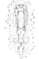
図1はボディカバーを想像線で表した自動二輪車1の車体構造を示す側面図、図2は同平面図で、これ等で車体構造のレイアウトの全体を示し、図3、図4は車体の前部構造を示す側面図、及び正面図である。
自動二輪車の前部〜中間部にエンジン2を配置し、エンジン2は、図4で示す如く、車幅方向の各両側に突出する略々水平なシリンダ部2a,2aを備える水冷式の水平対向式エンジンを用いた。
シリンダ部2a,2aは、図1、図3、図4に示すように、全体として矩形箱状の外観をなすクランクケース等を含むエンジンボディ2bを備え、前部の左右にシリンダ部2a,2aが外側方に略々水平に突出する。
【0011】
エンジン2のエンジンボディ2bの後部には、略々矩形ボックス状のミッションケース3を一体的に結合し、ミッションケース3はエンジン2の後部に後方に一体的に延出される。
これ等エンジン2とミッションケース3とで固定のパワーユニットを構成し、エンジン2、ミッションケース3は車体の一部を構成する。
以下にこれを詳細に説明する。
【0012】
前部車体の主要部を構成するメインフレーム4は、先端部のヘッドパイプ5、該ヘッドパイプ5の後半部周の下半部から後下傾するように延出された左右のメインパイプ6,6、又メインパイプ6,6の先端部下部から後下傾するように延出された左右のダウンチューブ7,7からなる。
メインパイプ6,6は縦長の角パイプ材で構成し、図2、図4で明らかなように、先端部がヘッドパイプ5に溶接し、平面視において、左右の部材の前後方向中間部が各外側方に膨出した形状である。
又ダウンチューブ7,7は、前後方向中間部で下方に略々平行な幅で屈曲、垂下する。
【0013】
左右のメインパイプ6,6の各後端部には、エンジン取付用ブラケット8,8を設け、該ブラケット8,8の下端部には、エンジンハンガー9,9を連結し、該エンジンハンガー9,9の下端部を、エンジン2のボディ2bの後部の高さ方向中間部の両側部に突出したボス部2c,2cにボルト9a,9aで結合する。又上方のブラケット8,8を、ボルト8a,8aを介してエンジンボディ部2bの後部の上部2dの両側部に結合する。
このように、メインパイプ6,6の後端部をエンジン2に取付、支持する。
尚、図3では、エンジンハンガー9をブラケット8と別体としたが、エンジンハンガーをブラケットの一部として構成しても良いし、又メインパイプ6の下端部を圧潰してブラケット状に形成し、このブラケット状部分をエンジン2のボディ部2bに結合しても良い。
【0014】
前方に配置した左右のダウンチューブ7,7の後端部には取付用ブラケット10,10を設ける。該ブラケット10,10を、エンジンボディ2bの前部の上部左右に設けたボス部2e,2eにボルト10a,10aを介して結合し、ダウンチューブ7,7をエンジン2に取付、支持する。
以上により前部のメインフレーム4を構成する。エンジン2は、前部のメインフレームの一部を構成し、メインフレーム4は、後方、且つ上方への構成部材であるメインパイプ6,6が後下傾してエンジン2にその後端部が結合されいるので、名フレーム4はエンジン後部から後方に、エンジン上方に突出することは無い。
【0015】
以上のダウンチューブ7,7の上下には、ラジエータ11を該ダウンチューブ7,7の前面に取付、支持するスティ7a,7bを設け、エンジン冷却用のラジエータ11を支持する。又エンジンボディ2bの中間部上で、左右のメインパイプ6,6間には、燃料供装置を構成するスロットル弁装置等で構成された気化器12を配設し、該気化器12の上方に、エアクリーナ13を連設するように配置した。
メインフレーム4の先端部を構成するヘッドパイプ5には、前輪14を支持するフロントフォーク15を回動可能に支持する。フロントフォーク15の上端部のトップブリッジ15a上に、ハンドルホルダー15bを介して左右方向の延びるバー式のハンドル16を設け、ハンドル16で前輪14を操舵する。
【0016】
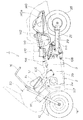
次に後部車体構造を図5、及び図6で説明する。
17はリヤフレームで、上部のリヤメインフレーム18は、図6に示すように平面視において後端部を閉じた前方に開く略々U字型である。リヤメインフレーム18は、左右の部材18a,18aの後端部を対向するように内側に曲げ、突き合せ端部を後端部材18bで連結し、後端を閉じた平面視略々U字型のフレームを構成する。
実施の形態では、図6に示したように一方の部材の中間部〜後部を、車幅の一側方に膨出し、左右部材18a,18aの中間後部間にクロス部材18cを架設し、又中間前部間にもクロス部材18dを架設する。
【0017】
リヤメインフレーム18の左右の部材18a,18aは、図5で明示したように、側面視においては、前部18eが低位で略々水平であり、中間部18fが後上傾して後方に延び、後部18gが高位で略々水平に後方に延びる。
リヤフレーム17の下部を構成するリヤサブフレーム19は、左右の部材19a,19aで構成される。左右の部材19a,19aは、図5に明示したように側面視が鈍角の略々L字型をなし、前部19bは、メインフレーム18の前部18eと上下方向に離間して位置し、短い長さで略々水平である。
【0018】
中間部19cは後上傾して後方に延び、後部19dは急角度で曲げられて上方に延び、メインフレーム18の左右の部材18a,18aの後上傾する中間部18fの後部近傍に下から溶接、結合されている。
図6で明示したように、一方側の部材は、メインフレーム18のこの側の外側方への膨出形状に合せて、他側よりも外側に膨出する。
【0019】
又左右の部材19a,19aの後部19dの下方部位間には、クロス部材19eを架設し、更に各上下の部材18a,19aの前部18eと後上傾する中間部19cとの間に、前上傾するように補強パイプ20,20を架設する。
尚、メインフレーム18とサブフレーム19との結合部分にかかるように、補強板19fを架設し、該補強板19fは、後述する緩衝器一端部の取付部を構成する。
又サブフレーム19の後部19dの上部後方に、後述する燃料タンク支持フレームを支持する支持ブラケット21,21を突設した。更に、サブフレーム19の後部には、後方へ延びる支持スティ22を突設した。
【0020】
前記したミッションケース3の後部の上部には、左右に離間してボス部3a,3aを突設し、該ボス部3a,3aに、上部のリヤメインフレーム18の左右の部材18a,18aの前部18e先端部を各ボルト3b,3bで結合する。
又下部のリヤサブフレーム19の左右の部材19a,19aの前部19b各先端部を、ミッションケース3の後部下部左右に前後に設けたボス部3c…(…は複数を表す。以下同じ)の外側に配置し、ボルト3d…で該ボス部3c…に結合する。
【0021】
以上により、リヤフレーム17を構成する上下のメインフレーム18、サブフレーム19の先端部は、ミッションケース3の後部の上下に結合されることとなり、ミッションケース3は車体後部構造の一部を構成し、前記したようにエンジン2は車体前部構造の一部を構成し、前後のフレーム4,17は、各部材を前後に分割して形成し、エンジン2、ミッションケース3を含むパワーユニットで、車体構造体の中間部を構成することとなる。
ミッションケース3内には、例えば静油圧式無段変速装置等の自動変速機を内蔵する構造とし、これに代え、電気式変速装置とし、変速操作部をハンドルグリップに設けても良い。
【0022】
ミッションケース3の後部には、左右に離間して軸支ボス部3e,3eを一体に設け、該軸支ボス部3e,3eに後輪支持用のリヤスイングアーム23の先端部を揺動自在に軸支する。
該スイングアーム23の構造は図7で詳細に示す如くで、実施の形態では後輪駆動機構をシャフトドライブ機構で構成した。
一方、図7で左側を自動二輪車の進行方向前方とし、従って右側にスイングアーム機能のみを備える一方のスイングアーム部材24とし、他方のスイングアーム部材25をドライブシャフト27を内部に通したドライブシャフトケースで構成する。尚、説明中において、25をスイングアーム、或いはドライブシャフトケースの双方の名称で記載する場合がある。
【0023】
左右のスイングアーム部材24,25の先端部間には、クロス部材26を架設して双方24,25を一体化し、該クロス部材26をスイングアーム23の揺動中心となる軸支部の中心として設定する。
クロス部材26の一端部には、軸方向に支軸28を突設し、該支軸28をこの側のボス部3eに設けた軸孔3fに軸受け3gを介して回転自在に支持する。
ドライブシャフトケース側のスイングアーム25の先端部25aには、大径のボス部25aを備え、該ボス部25aの外側面に支持凹部25bを設け、この側のミッションケース3側のボス部3eに支軸29を固着し、該支軸29を支持凹部25bに軸受け25cを介して回転自在に支持する。
【0024】
以上のミッションケース3側のボス部3e,3eに支持、或いは固定した軸28,29を支点として、スイングアーム23はミッションケース3に揺動自在に支持されることとなる。
ミッションケース3の変速出力軸30を、ミッションケース3の後方で、前記したドライブシャフト27に偏った側に延出する。該出力軸30の後端部と、ドライブシャフトケース25内に内装したドライブシャフト27の前端部間を、自在継手31を介して連結する。
尚、図7において32,33はシャフトドライブ機構中に介設したトルクリミッタである。
【0025】
ドライブシャフトケース25の後端部にはギヤケース34を一体的に設け、これと反対側のスイングアーム24の後端部間に後輪35の車軸35aを架設して、後輪35をスイングアーム後端部で支持する。
後輪35のハブ35bとこれの軸方向外側に配置した被動ギヤ36とを係合し、該被動ギヤ36とドライブシャフト27の後端部に設けた駆動ギヤ37とを噛合し、出力軸30の出力を、ドライブシャフト27、ギヤ37,36で後輪35に伝達し、後輪35を駆動する。尚、図7中において35cはブレーキディスク,35dはブレーキキャリパである。
図7で示したように、左右のスイングアーム部材24,25は、先端部の間隔が後端部の間隔よりも狭く設定し、後述するようにスイングアームの軸支部28,29を足載せフロアの内側に配置して、足載せフロアの車幅方向の大きさを、大きく設定することができるように構成した。
【0026】
図1で示したように、ギヤケース34と前記した補強板19fとの間には、リヤクッションユニットを構成する緩衝器38を介装し、又図1に示すように、ミッションケース3の後部下部にはスタンドブラケット39aを連結し、該ブラケット39aにスタンド39を起倒自在に取付、支持する。
尚、リヤフレーム17のサブフレーム19の左右の部材19a,19aの後方に突設したブラケット21,21には、図2で構造を示した燃料タンクの支持フレーム40の先端部40a,40aを結合して支持する。
支持フレーム40は、平面視が前方に開いた略々U字型をなし、後端部40bを、上部のリヤメインフレーム18の後端部材18bに、左右のスティ41,41を介して連結し、平面視略々U字型の燃料タンク42を該フレーム40で支持する。燃料タンク42のU字型空間内に、後輪35の上部が臨む。
【0027】
尚、図13で示したように、ミッションケース3の後方からリヤフレーム17の後部にかけて収納ボックス43を配設し、収納ボックス43は、後上傾し、平面視では図2に示すように前後方向に長い長円状をなし、前後に収納部を備え、低位の前部は前部収納部43aとし、又高位の後部は後部収納部43bとした。 前部収納部43aは深く、ヘルメット44をその頂部を後方に向け、シールド面を上方に向けて収納し、又後部収納部43bは後輪35の上方に位置し、ヘルメット44をその頂部を上方に向け、シールド面を前方に向けて収納する。
前部収納部43aは、ミッションケース3の後方で、後輪35の前方に位置して設けられる。後部収納部43bは、前部収納部43aより高い位置に設けられる。
かかる収納ボックス43の上は開放されており、収納ボックス43上をシート45で開閉自在に覆う。シート45は、前部のドライバーズ用シート部46、及びこれと一体に設けた後部のパッセンジャ用シート47を備える。
シート45は、図示しないが、一側部をヒンジとして起倒し、収納ボックス43の前後の収納部43a,43bを開閉するように構成した。
【0028】
以上の自動二輪車の車体構造体を含む各部を、ボディカバー50で覆う。
ボディカバー50の形状は、図8、及び図9で示す如くで、ボディカバー50の前部51は、下位のエンジン2、メインフレーム4の両側方、及びハンドル下方の後方部分を覆う。
前部51の上部は、前輪14の上方に位置するように前方に突出し、上部にはフロントウインドスクリーン53を起設し、又前部51には、左右にレッグシールド51aを備え、該レッグシールド51aの下端部は足載せフロア部58の先端部に繋がる。エンジン2のシリンダ部2bは、足載せフロア部58及びレッグシールド51aの前方に位置する。
51bはシリンダヘッドが臨む孔である。
【0029】
又ボディカバー50の下部は前輪14の後方に位置し、エンジン2の両側部を覆い、ハンドル16の周りにはハンドルカバー55、及びハンドルポストカバー56で覆い、ボディカバー50の前部を構成する。
ボディカバー50の中間部57は、前記したエンジン2の後部からミッションケース3にかけて前部51に連続するように設ける。
【0030】
中間部57の断面は図10〜図12に示す如くで、左右の足載せフロア部58,58、この間の中央部に上方に膨出した略々逆コ字型のフロアトンネル部59を備える。
トンネル部59の左右の側壁59a,59aの下端部59b,59bが、左右の足載せフロア部58,58の足載せ面58a,58aの車幅方向の内端部に連続し、足載せ面58a,58aの各外端部58b,58bが下方に少しく垂下し、更に各外端部58b,58bが、下方、且つ内側に対称的に傾斜するように垂下し、側壁部58c,58cを形成している。
【0031】
ミッションケース3は、前記したフロアトンネル部59内に上半部が収容され、ミッションケース3の上方部は上壁59cで、又左右両側部は側壁59a,59aで覆われる。
以上のフロアトンネル部59は、前記したようにミッションケース3の上部に車体フレームが無いので、ミッションケース3の上方、及び両側方を覆えば良く、従って、フロアトンネル部59の高さは可及的に低く設定することができる。
【0032】
又左右の足載せフロア部58,58は、ミッションケース3の両側部に配置され、車体フレームを構成する前後のフレーム4,17の制約を受けることが無いので、足載せ面58a,58aは、車幅方向一杯に、車幅の許容する範囲内で大きく設定することができる。
そして、前後も亦前記したフレーム4,17の制約が少ないので、前後長も大きく設定することができ、後席のパッセンジャの足載せ面を充分の大きさで確保することができる。
【0033】
尚、図11に示すように、スイングアーム23の軸支部28,29は、前記した図7に示すように、その間隔が狭いので、足載せフロア部58,58の下方で内側に位置するように配置することができる。
又左右のスイングアーム24,25は、後方に向けてその間隔を次第に広げるように平面視で後方に末広がりに構成しており、この関係は図12で明らかである。
【0034】
以上のボディカバー50の中間部57の後部にボディカバー後部60を設け、ボディカバー後部60は、シート45の周り、リヤフレーム17の両側部、後部、後輪35の上半部、スイングアーム23の後半部、収納ボックス43の周り等を全面的に覆うように構成する。
尚、ボディカバー後部60一側部で、一方の足載せフロア部58の後方の部分には、工具等の物入れ61を設け、リッド62の開閉で工具等を出し入れするように構成した。尚図1、図2で示す49は、車体の一方の後方に延出した消音器である。
【0035】
図14、及び図15は本発明の他の実施の形態を示すもので、前記した実施の形態と基本構造は同一なので、同一部分には同一符号を付し、詳細な説明は省略する。
ダウンチューブ107の構造を直線状に垂下した構造とし、又メインパイプ106の下端部を上下に広く形成し、エンジン2のボディ2bに結合した。又リヤフレーム117のメインフレーム118を直線状に後上傾するようにし、後端部を上方に起立させ、サブフレーム119を略々L字型とした。
【0036】
又リヤメインフレーム118の平面視略々U字型空間内に、前後にバッテリ170、燃料タンク142を配置し、図15で明示したように、リヤフレーム後方に収納ボックス支持フレーム140を平面視で左右に膨出した囲枠状に設け、これの中間部を前後に設けたスティ140a,140aで上部のメインフレーム118の後端部に連結し、収納ボックス支持フレーム140内に左右に幅が大きい収納ボックス143を配置し、ヘルメット44,44を左右に振り分けて収納した。
【0037】
更にスイングアーム23の懸架装置であるが、ミッションケース3の後部上部に緩衝器138の一端部を連結し、緩衝器138の他端部を、プログレシブリンク機構171を介してスイングアーム23に連結し、クッション特性を斬増するように構成した。
又ラジエータ111を、図15で明らかなように、フロントフォーク15の左右に分割して配置した。
その余の構成は、前記した実施の形態と略々同様である。
【0038】
【発明の効果】
本発明は上記構成により次の効果を発揮する。
請求項1は、前輪後方に位置するボディカバーと、該ボディにつながる左右に低床式の足載せフロアを備え、該左右のフロア間に上方に膨出し、前後方向に延びるフロアトンネルを備える自動二輪車において、シリンダ部を車幅方向の両側に突出した水平対向式エンジンを前部に配置し、ミッションケースを該水平対向式エンジンに連結して後方に一体的に延出するように配置し、前部の水平対向式エンジンを、足載せフロア前方のボディカバー内に配置するとともに、後部のミッションケースを、足載せフロア間のフロアトンネル内に収納配置し、車体前部のメインフレームの後端部を、前記水平対向式エンジンに取付、支持し、ミッションケース後端部に後輪支持用のスイングアームを揺動自在に支持した前部のメインフレームの後端部は、エンジンに取付、支持することとなり、足載せフロア後方まで、車体の前部フレームが延出することが無くなる。
【0039】
従って、車体前部のメインフレームは、足載せフロアに影響することが無くなり、足載せフロアに対する前部のフレームによる制約が無くなり、足載せフロアを、車幅の制約内で、フレームに影響されること無く、車幅方向に対して可及的に大きく採ることができ、又前後方向も可及的に大きく採ることができる。
この結果、乗員の足載せ性が向上し、乗車性の良好な、運転性に優れたスクータのような低床式の自動二輪車を得ることができる。
又足載せフロアを、幅、前後長ともに大きく設定できるので、特に制約の多かった後席のパッセンジャの足載せ性、乗車性を向上させることができ、2人乗りの大型のこの種自動二輪車において、極めて有利な足載せ機能、乗車機能を有する自動二輪車をえることができる。
【0040】
更にフロアトンネル内にミッションケースを収納したので、ミッションケースはトンネルで覆われ、外観性が向上する、という効果も有する。
又フロアトンネル内に収納したミッションケースの後端部に、後輪支持用のスイングアームを支持したので、スイングアームの支持部分を可及的に低い位置に配置することができ、足載せフロアへのスイングアームの支持部の影響、制約を少なくでき、足載せフロアをスイングアーム支持部に影響されことなく大きく設定することができ、前記と併せ、足載せフロアを大きくすることの実効性を得ることができる。
【0041】
請求項2は、請求項1において、前部のメインフレームと、後部のリヤフレームとを分割して形成し、後部のリヤフレームを、ミッションケースの後部に取付、支持したので、前記した請求項1の効果に加えるに、左右の足載せフロア間のフロアトンネル部分にフレームが配置されことが無くなる。
従って、左右の足載せフロア間のフロアトンネル部分は、この部分にフレームが配置されないので、フロアトンネル部分の高さを可及的に低く抑えることができる。
この結果、低床式自動二輪車の乗降に際し、跨がざるを得ないフロアトンネル部分が可及的に低くなり、乗降の邪魔になることが無く、この種自動二輪車の乗降性が著しく向上し、乗降性に優れた使い勝手性の優れたスクータのような自動二輪車を得ることができる。
【0042】
更に、前後のフレームを分割して形成し、前部のメインフレームの後端部をエンジンに、後部のリヤフレームをミッションケースに各取付、支持したので、フレームはエンジン、これと一体のミッションケースで支持されて直接前後のフレームは結合されることがなく、エンジン、ミッションケースは車体の不可欠の一部を構成することとなり、従って、車体フレーム全体の構造が簡素となり、又剛性の高いエンジン、ミッションケースが車体の一部を構成することとなり、車体剛性も、格別の補強構造を必要とすること無く高剛性を維持することができる。この結果、車体フレーム構造の部品点数の減少、簡素化、製作の容易化等を図ることも可能である。
請求項3は、請求項1において、左右のスイングアームは先端部の間隔が後端部の間隔よりも狭く設定し、スイングアームの軸支部を足載せフロアの内側に配置したので、足載せフロアの車幅方向の大きさを、大きく設定することができる。
【図面の簡単な説明】
【図1】本発明にかかる低床式自動二輪車の車体構造を示す側面図
【図2】図1の平面図
【図3】前部の車体構造を示す側面図
【図4】図3の正面図
【図5】後部の車体構造を示す側面図
【図6】図5の平面図
【図7】スイングアーム部分の一部を断面とした平面図
【図8】図1の自動二輪車の外観側面図
【図9】図8の平面図
【図10】ボディカバーを取り付けた状態における図1の10−10線断面図
【図11】ボディを取り付けた状態における図1の11−11線断面図
【図12】ボディカバーを取り付けた状態における図1の12−12線断面図
【図13】後部の車体の拡大側面図で、シート、収納ボックス部分を断面とした図
【図14】他の実施例の図1と同様の側面図
【図15】図14の平面図
【符号の説明】
1…自動二輪車、 2…水平対向式エンジン、 2a…シリンダ部、 3ミッションケース、 4…前部のメインフレーム、 17…後部のリヤフレーム、 23…スイングアーム、 35…後輪、 58…足載せフロア、 59…フロアトンネル部。[0001]
BACKGROUND OF THE INVENTION
The present invention relates to a vehicle body structure of a low-floor motorcycle such as a scooter, and in particular, a vehicle body frame is formed by dividing it into front and rear parts, and these front and rear frames are connected to a horizontally opposed engine and the rear thereof to be integrated. The present invention relates to a vehicle body structure of a low-floor type motorcycle in which a vehicle body is configured by being attached to and supported by each of the extended transmission cases so as to expand a footrest floor and improve getting on and off.
[0002]
[Prior art]
The motorcycle body structure is a motorcycle type, for example(1)A structure such as Japanese Patent No. 2593868 is known, and as a scooter type,(2) SpecialA structure such as that disclosed in Japanese Patent Publication No. 37-16106 is known.
the above(1)The body structure is generally adopted for motorcycles, and the front and rear frames are directly joined to form the body frame. The engine is mounted and supported by hanging it from the body frame with an engine hanger. is doing.
Even in a scooter type motorcycle, although the shape and specific structure are different,(1)The vehicle body structure is the same. the above(2)In this technique, the vehicle body frame is formed of a so-called monocoque structure, and the engine and a swing arm for supporting the rear wheels are attached to and supported by the vehicle body.
[0003]
[Problems to be solved by the invention]
By the way, in a low floor type motorcycle such as a scooter having a footrest floor at a low position,(1)As is known in, directly connect the front and rear body frames or similarBodyWhen the structure is adopted, the connecting part of the front and rear frames and the rear part of the front frame are located in the middle part of the vehicle body, and the frame is located in the middle part in the longitudinal direction of the vehicle body, that is, the footrest floor part. However, it becomes a restriction in securing the footrest floor, it is difficult to secure a sufficient area of the footrest floor, and the footrest floor becomes narrow.
Also, since the frame is arranged in the tunnel part where the occupant between the footrest floors straddles, the tunnel part inevitably becomes high due to the frame, the tunnel part is difficult to straddle, as a low floor scooter in terms of getting on and off It is hard to say that it is optimal.
[0004]
on the other hand,(2)When the body of a low-floor type motorcycle is formed with a monocoque frame as described above, the appearance of the vehicle is formed with a monocoque body, so the degree of freedom in design is great. On the other hand, each part of the body frame that directly configures the external parts requires press forming of large parts with steel plates, and for press forming of steel plates, in order to ensure rigidity, the complicated structure, the number of parts increases, In addition, a large number of parts, a large number of places, complicated welding, and the like are required, making the production complicated. As a result, there is a possibility that the weight may increase, and there is a risk of further increasing the cost.
For this reason, it is generally performed that the frame is formed by welding and joining a metal pipe material, and the body forming the appearance is formed by a resin molded product.
[0005]
The inventors of the present invention have made the present invention to solve the above-described problems. The footrest floor of a motorcycle having a lower footrest floor is taken as large as possible in both the vehicle width and the front and rear. It is easy to ride, easy to drive, and the height of the tunnel part arranged between the footrest floors is kept as low as possible, so that it is easy to straddle when getting on and off, and to improve the getting on and off, An object of the present invention is to provide a vehicle body structure for a low floor type motorcycle.
Another object of the present invention is to provide a vehicle body structure for a low floor type motorcycle that can simplify the vehicle body structure.
[0006]
[Means for Solving the Problems]
In order to solve the above-mentioned problem, claim 1A body cover located behind the front wheel and connected to the bodyA horizontally-opposed engine that has a low-floor type footrest floor on the left and right, a cylinder that protrudes on both sides in the vehicle width direction in a motorcycle that has a floor tunnel that bulges upward between the left and right floors and extends in the front-rear direction. Is arranged at the front, the transmission case is connected to the horizontally opposed engine and is arranged so as to extend integrally rearward, and the front horizontally opposed engine is connected to the front of the footrest floor.In the body coverThe rear transmission case is housed in a floor tunnel between the footrest floors, and the rear end of the main frame at the front of the vehicle body is attached to and supported by the horizontally opposed engine. A swing arm for supporting the rear wheels is supported at the rear end of the case so that it can swing.It is characterized by that.
[0007]
Since the rear end of the front main frame is attached to and supported by the engine, the front frame of the vehicle body does not extend to the rear of the footrest floor, and there is no restriction of the footrest floor by the main frame, A large footrest floor can be taken.
[0008]
Since the main frame and the rear rear frame are divided and formed, and the rear frame is attached to and supported by the rear portion of the transmission case, the second aspect of the present invention is the floor tunnel portion between the left and right footrest floors. Since the frame is not arranged on the floor, the height of the floor tunnel portion can be kept low.
According to a third aspect of the present invention, in the first aspect, the left and right swing arms are set such that the distance between the front ends is narrower than the distance between the rear ends, and the shaft support portion of the swing arm is disposed inside the footrest floor. .
According to the third aspect, the size of the footrest floor in the vehicle width direction can be set large.
[0009]
DETAILED DESCRIPTION OF THE INVENTION
Embodiments of the present invention will be described below with reference to the accompanying drawings. The drawings are viewed in the direction of the reference numerals.
1 is a side view showing a vehicle body structure of a low floor type motorcycle according to the present invention, FIG. 2 is a plan view thereof, FIG. 3 is a side view showing a vehicle body structure of a front portion, FIG. 4 is a front view thereof, and FIG. FIG. 6 is a plan view of the rear vehicle body structure, FIG. 7 is a plan view of a part of the swing arm portion, FIG. 8 is a side view of the motorcycle shown in FIG. 1, and FIG. 10 is a cross-sectional view taken along line 10-10 in FIG. 1 with the body cover attached, FIG. 11 is a cross-sectional view taken along line 11-11 in FIG. 1 with the body attached, and FIG. 12 is a view with the body cover attached. FIG. 13 is a sectional view taken along line 12-12 of FIG.
[0010]
FIG. 1 is a side view showing a vehicle body structure of a
The
As shown in FIGS. 1, 3, and 4, the
[0011]
A substantially rectangular box-
The
This will be described in detail below.
[0012]
The
The
Further, the
[0013]
At the rear ends of the left and right
As described above, the rear end portions of the
In FIG. 3, the
[0014]
Mounting
The front
[0015]
Above and below the
A
[0016]
Next, the rear vehicle body structure will be described with reference to FIGS.
In the embodiment, as shown in FIG. 6, the middle part to the rear part of one member bulges to one side of the vehicle width, and a
[0017]
As clearly shown in FIG. 5, the left and
A
[0018]
The
As clearly shown in FIG. 6, the member on one side bulges outward from the other side in accordance with the bulging shape of the
[0019]
Further, a cross member 19e is installed between the lower portions of the
In addition, a reinforcing plate 19f is installed so as to cover the connecting portion between the
In addition,
[0020]
Further, the front ends 19b of the left and
[0021]
As described above, the top ends of the upper and lower
The
[0022]
The rear part of the
The structure of the
On the other hand, in FIG. 7, the left side is the front in the traveling direction of the motorcycle, and thus the right side is one
[0023]
Between the front ends of the left and right
At one end of the
The
[0024]
The
The
In FIG. 7, 32 and 33 are torque limiters interposed in the shaft drive mechanism.
[0025]
A
The
As shown in FIG. 7, the left and right
[0026]
As shown in FIG. 1, a
The
The
[0027]
As shown in FIG. 13, a
The
The top of the
Although not shown, the
[0028]
Each part including the above-described motorcycle body structure is covered with a
The shape of the
The upper portion of the
51b is a hole that the cylinder head faces.
[0029]
orBody cover 50The lower portion of the engine is located behind the
The
[0030]
The cross section of the
The
[0031]
The
As described above, since the
[0032]
Further, the left and right
Since the front and
[0033]
As shown in FIG. 11, the
Further, the left and
[0034]
A body cover
still,Body cover
[0035]
14 and 15 show another embodiment of the present invention. Since the basic structure is the same as that of the above-described embodiment, the same parts are denoted by the same reference numerals, and detailed description thereof is omitted.
The structure of the
[0036]
Also, a
[0037]
Further, as a suspension device for the
Further, as is apparent from FIG. 15, the
The rest of the configuration is substantially the same as in the above-described embodiment.
[0038]
【The invention's effect】
The present invention exhibits the following effects by the above configuration.
Claim 1In a motorcycle provided with a body cover located at the rear of the front wheel and low floor type footrest floors connected to the body on the left and right sides, and a floor tunnel that bulges upward between the left and right floors and extends in the front-rear direction. A horizontally opposed engine that protrudes on both sides in the vehicle width direction is arranged at the front, and the transmission case is connected to the horizontally opposed engine so as to extend integrally rearward. While placing the engine in the body cover in front of the footrest floor,The rear transmission case is housed in the floor tunnel between the footrest floors, the rear end of the main frame at the front of the vehicle body is attached to and supported by the horizontally opposed engine, and the rear wheel is mounted on the rear end of the transmission case. The rear end portion of the front main frame that supports the swing arm for swinging is attached to and supported by the engine, and the front frame of the vehicle body does not extend to the rear of the footrest floor. .
[0039]
Therefore, the main frame at the front of the vehicle body does not affect the footrest floor, and there is no restriction by the front frame for the footrest floor, and the footrest floor is affected by the frame within the constraints of the vehicle width. Therefore, it can be taken as large as possible in the vehicle width direction, and can be taken as large as possible in the front-rear direction.
As a result, it is possible to obtain a low-floor type motorcycle such as a scooter that has improved occupant footing, good rideability, and excellent drivability.
In addition, because the footrest floor can be set large in both width and front and back length, it is possible to improve the footrest and rideability of passengers in the rear seat, which are particularly restricted, and in this type of two-seater large motorcycle Thus, a motorcycle having a very advantageous footrest function and riding function can be obtained.
[0040]
Further, since the transmission case is housed in the floor tunnel, the transmission case is covered with the tunnel, and the appearance is improved.
In addition, since the rear wheel support swing arm is supported at the rear end of the transmission case housed in the floor tunnel, the swing arm support can be placed as low as possible to the footrest floor. The influence and restriction of the swing arm support portion can be reduced, the footrest floor can be set large without being affected by the swingarm support portion, and in addition to the above, the effectiveness of increasing the footrest floor can be obtained. be able to.
[0041]
According to a second aspect of the present invention, in the first aspect, the front main frame and the rear rear frame are divided and formed, and the rear frame is attached to and supported by the rear portion of the transmission case. In addition to the
Therefore, the floor tunnel portion between the left and right footrest floors is not provided with a frame at this portion, so that the height of the floor tunnel portion can be kept as low as possible.
As a result, when getting on and off a low floor motorcycle, the floor tunnel part that must be straddled becomes as low as possible, without getting in the way of getting on and off, the getting on and off of this kind of motorcycle is significantly improved, A motorcycle like a scooter with excellent ease of getting on and off can be obtained.
[0042]
In addition, the front and rear frames are divided and formed. The rear end of the main frame is attached to the engine and the rear frame is attached to and supported by the transmission case. The front and rear frames are not directly connected to each other, and the engine and the transmission case constitute an indispensable part of the vehicle body. Therefore, the structure of the entire vehicle body frame is simplified, and the rigid engine, The transmission case constitutes a part of the vehicle body, and the vehicle body rigidity can be maintained at a high rigidity without requiring a special reinforcing structure. As a result, the number of parts of the vehicle body frame structure can be reduced, simplified, and easy to manufacture.
According to a third aspect of the present invention, in the first aspect, the left and right swing arms are set such that the distance between the front ends is smaller than the distance between the rear ends, and the pivot support portion of the swing arm is disposed inside the footrest floor. The size in the vehicle width direction can be set large.
[Brief description of the drawings]
FIG. 1 is a side view showing a vehicle body structure of a low floor type motorcycle according to the present invention.
FIG. 2 is a plan view of FIG.
FIG. 3 is a side view showing the front body structure.
4 is a front view of FIG. 3. FIG.
FIG. 5 is a side view showing the rear body structure.
6 is a plan view of FIG. 5. FIG.
FIG. 7 is a plan view with a part of the swing arm section taken as a cross section.
Fig. 8 is an external side view of the motorcycle shown in Fig. 1;
FIG. 9 is a plan view of FIG.
10 is a cross-sectional view taken along the line 10-10 of FIG. 1 with the body cover attached.
11 is a cross-sectional view taken along line 11-11 in FIG. 1 with the body attached.
12 is a cross-sectional view taken along line 12-12 of FIG. 1 with the body cover attached.
FIG. 13 is an enlarged side view of the rear vehicle body, with the section of the seat and storage box taken as a cross section.
14 is a side view similar to FIG. 1 of another embodiment.
15 is a plan view of FIG.
[Explanation of symbols]
DESCRIPTION OF
Claims (3)
シリンダ部を車幅方向の両側に突出した水平対向式エンジンを前部に配置し、ミッションケースを該水平対向式エンジンに連結して後方に一体的に延出するように配置し、
前記前部の水平対向式エンジンを、前記足載せフロア前方のボディカバー内に配置するとともに、前記後部のミッションケースを、前記足載せフロア間のフロアトンネル内に収納配置し、
車体前部のメインフレームの後端部を、前記水平対向式エンジンに取付、支持し、
前記ミッションケース後端部に後輪支持用のスイングアームを揺動自在に支持した、
ことを特徴とする低床式自動二輪車の車体構造。 In a motorcycle provided with a body cover located at the rear of the front wheel and low floor type footrest floors connected to the body on the left and right sides, and a floor tunnel that bulges upward between the left and right floors and extends in the front-rear direction.
A horizontally opposed engine with the cylinder part projecting on both sides in the vehicle width direction is disposed at the front part, and the transmission case is disposed so as to be connected integrally to the horizontally opposed engine and extend rearwardly,
The front horizontally opposed engine is disposed in a body cover in front of the footrest floor, and the rear transmission case is accommodated in a floor tunnel between the footrest floors,
Attach and support the rear end of the main frame at the front of the vehicle body to the horizontally opposed engine,
A swing arm for supporting the rear wheel is swingably supported at the rear end of the transmission case.
A low-floor motorcycle body structure characterized by that.
Priority Applications (3)
| Application Number | Priority Date | Filing Date | Title |
|---|---|---|---|
| JP26749997A JP3816210B2 (en) | 1997-09-30 | 1997-09-30 | Body structure of a low-floor motorcycle |
| IT1998TO000818A IT1305579B1 (en) | 1997-09-30 | 1998-09-29 | BODY STRUCTURE OF A LOWERED FOOTBOARD MOTORCYCLE. |
| US09/163,425 US6073719A (en) | 1997-09-30 | 1998-09-30 | Body structure of a low floor motorcycle |
Applications Claiming Priority (2)
| Application Number | Priority Date | Filing Date | Title |
|---|---|---|---|
| JP26749997A JP3816210B2 (en) | 1997-09-30 | 1997-09-30 | Body structure of a low-floor motorcycle |
| US09/163,425 US6073719A (en) | 1997-09-30 | 1998-09-30 | Body structure of a low floor motorcycle |
Publications (2)
| Publication Number | Publication Date |
|---|---|
| JPH11105764A JPH11105764A (en) | 1999-04-20 |
| JP3816210B2 true JP3816210B2 (en) | 2006-08-30 |
Family
ID=26547900
Family Applications (1)
| Application Number | Title | Priority Date | Filing Date |
|---|---|---|---|
| JP26749997A Expired - Fee Related JP3816210B2 (en) | 1997-09-30 | 1997-09-30 | Body structure of a low-floor motorcycle |
Country Status (3)
| Country | Link |
|---|---|
| US (1) | US6073719A (en) |
| JP (1) | JP3816210B2 (en) |
| IT (1) | IT1305579B1 (en) |
Families Citing this family (51)
| Publication number | Priority date | Publication date | Assignee | Title |
|---|---|---|---|---|
| JP3620311B2 (en) * | 1998-10-27 | 2005-02-16 | スズキ株式会社 | Motorcycle storage equipment |
| JP4394769B2 (en) * | 1999-03-30 | 2010-01-06 | 本田技研工業株式会社 | Motorcycle helmet storage device |
| JP4364341B2 (en) * | 1999-03-31 | 2009-11-18 | 本田技研工業株式会社 | Article storage device for motorcycle |
| TW446664B (en) * | 1999-05-25 | 2001-07-21 | Honda Motor Co Ltd | Scooter type motorcycle |
| JP3788155B2 (en) * | 2000-01-11 | 2006-06-21 | スズキ株式会社 | Small vehicle engine unit |
| JP4058874B2 (en) * | 2000-02-07 | 2008-03-12 | スズキ株式会社 | Scooter type motorcycle |
| JP4058884B2 (en) * | 2000-05-23 | 2008-03-12 | スズキ株式会社 | Motorcycle rear wheel suspension system |
| JP3829585B2 (en) * | 2000-05-30 | 2006-10-04 | スズキ株式会社 | Motorcycle power unit |
| JP3971549B2 (en) * | 2000-06-09 | 2007-09-05 | 本田技研工業株式会社 | Scooter type motorcycle |
| JP3879437B2 (en) * | 2000-06-23 | 2007-02-14 | スズキ株式会社 | Motorcycle article storage device |
| JP4075296B2 (en) * | 2000-08-30 | 2008-04-16 | スズキ株式会社 | Scooter type motorcycle |
| JP3956594B2 (en) * | 2000-08-31 | 2007-08-08 | スズキ株式会社 | Motorcycle article storage device |
| JP3980819B2 (en) * | 2000-09-06 | 2007-09-26 | 本田技研工業株式会社 | Rear-wheel suspension structure for motorcycles |
| JP3831186B2 (en) * | 2000-09-08 | 2006-10-11 | 本田技研工業株式会社 | Motorcycle storage box structure |
| JP3529738B2 (en) * | 2000-09-08 | 2004-05-24 | 本田技研工業株式会社 | Vehicle parking device layout structure |
| JP2002097917A (en) * | 2000-09-21 | 2002-04-05 | Suzuki Motor Corp | Engine unit for vehicle |
| JP4118544B2 (en) * | 2001-09-17 | 2008-07-16 | 本田技研工業株式会社 | Radiator support structure |
| US6688628B2 (en) | 2001-10-17 | 2004-02-10 | Robert C. Burkett | Motorcycle bracket |
| ES2326958T3 (en) * | 2001-11-22 | 2009-10-22 | Honda Giken Kogyo Kabushiki Kaisha | SCOOTER TYPE MOTORCYCLE. |
| JP3899006B2 (en) * | 2001-12-14 | 2007-03-28 | ヤマハ発動機株式会社 | Scooter type motorcycle body frame |
| CA2421281C (en) * | 2001-12-20 | 2008-07-15 | Arctic Cat Inc. | Tandem four-wheel vehicle |
| JP4253464B2 (en) * | 2002-04-26 | 2009-04-15 | ヤマハ発動機株式会社 | Motorcycle |
| JP4093929B2 (en) * | 2003-07-11 | 2008-06-04 | 本田技研工業株式会社 | Fuel cell vehicle |
| JP4163585B2 (en) * | 2003-09-30 | 2008-10-08 | 本田技研工業株式会社 | Motorcycle body structure |
| JP4381768B2 (en) * | 2003-10-10 | 2009-12-09 | 本田技研工業株式会社 | Motorcycle storage equipment |
| US7255191B2 (en) * | 2003-10-31 | 2007-08-14 | Vectrix Corporation | Composite construction vehicle frame |
| JP2006088892A (en) * | 2004-09-24 | 2006-04-06 | Yamaha Motor Co Ltd | Saddle riding type vehicle |
| ITTO20050666A1 (en) * | 2004-09-29 | 2006-03-30 | Honda Motor Co Ltd | MOTORCYCLE |
| JP2006096274A (en) * | 2004-09-30 | 2006-04-13 | Honda Motor Co Ltd | Swing arm pivot structure in motorcycle and motor tricycle, and motorcycle and motor tricycle |
| US7942447B2 (en) | 2004-12-30 | 2011-05-17 | American Off-Road Technologies, Llc | Frame design for reduced-size vehicle |
| CA2603040A1 (en) * | 2005-03-31 | 2006-10-05 | Spirit Motorcycle Technology Ltd | Motorcycle |
| US7096846B1 (en) * | 2005-07-01 | 2006-08-29 | Harley-Davidson Motor Company Group, Inc. | Engine and transmission case assembly |
| JP4767603B2 (en) * | 2005-07-04 | 2011-09-07 | ヤマハ発動機株式会社 | Power unit and straddle-type vehicle equipped with the power unit |
| US20070063518A1 (en) * | 2005-09-22 | 2007-03-22 | Galyen Michael W | AC/DC power unit to replace fuel burning engines |
| JP4532380B2 (en) * | 2005-09-29 | 2010-08-25 | 本田技研工業株式会社 | Motorcycle |
| JP2007137408A (en) * | 2005-10-17 | 2007-06-07 | Yamaha Motor Co Ltd | Saddle riding type vehicle |
| JP4855086B2 (en) * | 2006-01-31 | 2012-01-18 | 本田技研工業株式会社 | Support structure of swing arm |
| JP2007320533A (en) * | 2006-06-05 | 2007-12-13 | Yamaha Motor Co Ltd | Motor-bicycle |
| CN101468696B (en) * | 2007-10-31 | 2015-01-21 | 雅马哈发动机株式会社 | Motor two-wheeler |
| JP5112092B2 (en) * | 2008-01-31 | 2013-01-09 | 本田技研工業株式会社 | Rear frame mounting structure for motorcycles |
| DE102008021981A1 (en) * | 2008-05-02 | 2009-11-05 | Bayerische Motoren Werke Aktiengesellschaft | Two-wheeler, especially scooter or motorcycle |
| TW201031562A (en) * | 2009-02-26 | 2010-09-01 | Kwang Yang Motor Co | Storage chamber for scooter type motorcycle |
| US20110036657A1 (en) * | 2009-08-13 | 2011-02-17 | Brammo, Inc. | Electric vehicle chassis |
| JP5520623B2 (en) * | 2010-01-29 | 2014-06-11 | 本田技研工業株式会社 | Fuel supply device |
| CN102372055B (en) * | 2010-08-20 | 2014-04-09 | 雅马哈发动机株式会社 | Pedal motorcycle |
| JP5694789B2 (en) * | 2011-01-17 | 2015-04-01 | 本田技研工業株式会社 | Fuel tank support structure for saddle-ride type vehicles |
| EP3028931B1 (en) * | 2013-07-31 | 2018-09-19 | Honda Motor Co., Ltd. | Motorcycle body cover structure |
| US9919657B2 (en) | 2015-09-04 | 2018-03-20 | Arctic Cat, Inc. | Retaining device for vehicle racks |
| DE102015222522A1 (en) * | 2015-11-16 | 2017-05-18 | Bayerische Motoren Werke Aktiengesellschaft | motorcycle |
| JP2018090175A (en) * | 2016-12-06 | 2018-06-14 | ヤマハ発動機株式会社 | Saddle-riding type vehicle and method of installing tracking device to saddle-riding type vehicle |
| TWM610118U (en) * | 2020-06-22 | 2021-04-11 | 光陽工業股份有限公司 | Straddle-type vehicle with liquid cooling device |
Family Cites Families (14)
| Publication number | Priority date | Publication date | Assignee | Title |
|---|---|---|---|---|
| JPS6216106Y2 (en) * | 1980-03-06 | 1987-04-23 | ||
| JPS57121380U (en) * | 1981-01-23 | 1982-07-28 | ||
| US4694929A (en) * | 1985-01-18 | 1987-09-22 | Sanshin Kogyo Kabushiki Kaisha | Frame body of motorcycles |
| JPS6229481A (en) * | 1985-07-30 | 1987-02-07 | 本田技研工業株式会社 | Brake cooling structure of motorcycle |
| US4721178A (en) * | 1985-08-08 | 1988-01-26 | Honda Giken Kogyo Kabushiki Kaisha | Multi-wheeled vehicle |
| FR2594401B1 (en) * | 1986-02-18 | 1991-10-25 | Honda Motor Co Ltd | MOTORCYCLE WITH FRONT WHEEL MOUNTED ON TWO UPPER AND LOWER OSCILLATING ARMS |
| JP2528288B2 (en) * | 1986-08-21 | 1996-08-28 | 本田技研工業株式会社 | Air cleaner device for motorcycles |
| JP2593868B2 (en) * | 1987-04-24 | 1997-03-26 | スズキ株式会社 | Motorcycle frame structure |
| US4964483A (en) * | 1987-09-25 | 1990-10-23 | Honda Giken Kogyo Kabushiki Kaisha | Motor scooter |
| US4903483A (en) * | 1988-02-17 | 1990-02-27 | Yamaha Hatsudoki Kabushiki Kaisha | Exhaust system for V-type engine |
| JP2847372B2 (en) * | 1988-09-27 | 1999-01-20 | 本田技研工業株式会社 | Scooter type vehicle |
| US5433286A (en) * | 1988-09-27 | 1995-07-18 | Honda Giken Kogyo Kabushiki Kaisha | Motorcycle |
| JP2918116B2 (en) * | 1989-06-22 | 1999-07-12 | ヤマハ発動機株式会社 | Fuel supply structure of scooter type motorcycles and tricycles |
| US5782313A (en) * | 1991-11-01 | 1998-07-21 | Yamaha Hatsudoki Kabushiki Kaisha | Double swing arm motorcycle front suspension |
-
1997
- 1997-09-30 JP JP26749997A patent/JP3816210B2/en not_active Expired - Fee Related
-
1998
- 1998-09-29 IT IT1998TO000818A patent/IT1305579B1/en active
- 1998-09-30 US US09/163,425 patent/US6073719A/en not_active Expired - Fee Related
Also Published As
| Publication number | Publication date |
|---|---|
| ITTO980818A1 (en) | 2000-03-29 |
| US6073719A (en) | 2000-06-13 |
| JPH11105764A (en) | 1999-04-20 |
| IT1305579B1 (en) | 2001-05-09 |
Similar Documents
| Publication | Publication Date | Title |
|---|---|---|
| JP3816210B2 (en) | Body structure of a low-floor motorcycle | |
| US7270210B2 (en) | Body frame for motorcycle | |
| JP3899006B2 (en) | Scooter type motorcycle body frame | |
| JP6134586B2 (en) | Saddle riding vehicle | |
| JP3585378B2 (en) | Rear swing arm structure for saddle-ride type vehicles | |
| US20090229908A1 (en) | Motorcycle | |
| EP1818249B1 (en) | Motorcycle comprising a rear cushion arrangement structure | |
| JP3836225B2 (en) | Frame structure of saddle-ride type vehicle | |
| JP2006315657A (en) | Arrangement structure for muffler and brake pedal of motorcycle | |
| JPH1159542A (en) | Body structure of motorcycle | |
| JP7163392B2 (en) | straddle-type vehicle | |
| JP6649971B2 (en) | Saddle type vehicle | |
| JP3792851B2 (en) | Frame structure of saddle-ride type vehicle | |
| JP3795199B2 (en) | Low floor motorcycle | |
| JP4153069B2 (en) | Rear cushion unit mounting structure for scooter type vehicles | |
| JP4129074B2 (en) | Scooter type motorcycle body frame | |
| JPH08253188A (en) | Rear wheel suspension device of bicycle | |
| JP3676487B2 (en) | Scooter type vehicle | |
| JPH06107264A (en) | Rear wheel suspension for bicycle | |
| JP2003237659A (en) | Scooter type motorcycle | |
| JPH0413194B2 (en) | ||
| JPH02175483A (en) | Front wheel suspension device for scooter type vehicle | |
| JPH11286292A (en) | Body frame for scooter type motorcycle | |
| JP3948819B2 (en) | Scooter type motorcycle body frame | |
| JP4240592B2 (en) | Motorcycle rear suspension structure |
Legal Events
| Date | Code | Title | Description |
|---|---|---|---|
| A521 | Written amendment |
Free format text: JAPANESE INTERMEDIATE CODE: A523 Effective date: 20040806 |
|
| A621 | Written request for application examination |
Free format text: JAPANESE INTERMEDIATE CODE: A621 Effective date: 20040806 |
|
| A131 | Notification of reasons for refusal |
Free format text: JAPANESE INTERMEDIATE CODE: A131 Effective date: 20060314 |
|
| A521 | Written amendment |
Free format text: JAPANESE INTERMEDIATE CODE: A523 Effective date: 20060511 |
|
| TRDD | Decision of grant or rejection written | ||
| A01 | Written decision to grant a patent or to grant a registration (utility model) |
Free format text: JAPANESE INTERMEDIATE CODE: A01 Effective date: 20060606 |
|
| A61 | First payment of annual fees (during grant procedure) |
Free format text: JAPANESE INTERMEDIATE CODE: A61 Effective date: 20060607 |
|
| R150 | Certificate of patent or registration of utility model |
Free format text: JAPANESE INTERMEDIATE CODE: R150 |
|
| FPAY | Renewal fee payment (event date is renewal date of database) |
Free format text: PAYMENT UNTIL: 20090616 Year of fee payment: 3 |
|
| FPAY | Renewal fee payment (event date is renewal date of database) |
Free format text: PAYMENT UNTIL: 20100616 Year of fee payment: 4 |
|
| FPAY | Renewal fee payment (event date is renewal date of database) |
Free format text: PAYMENT UNTIL: 20110616 Year of fee payment: 5 |
|
| LAPS | Cancellation because of no payment of annual fees |