JP3585378B2 - Rear swing arm structure for saddle-ride type vehicles - Google Patents
Rear swing arm structure for saddle-ride type vehicles Download PDFInfo
- Publication number
- JP3585378B2 JP3585378B2 JP27863898A JP27863898A JP3585378B2 JP 3585378 B2 JP3585378 B2 JP 3585378B2 JP 27863898 A JP27863898 A JP 27863898A JP 27863898 A JP27863898 A JP 27863898A JP 3585378 B2 JP3585378 B2 JP 3585378B2
- Authority
- JP
- Japan
- Prior art keywords
- swing arm
- rear swing
- saddle
- type vehicle
- arm
- Prior art date
- Legal status (The legal status is an assumption and is not a legal conclusion. Google has not performed a legal analysis and makes no representation as to the accuracy of the status listed.)
- Expired - Fee Related
Links
Images


Classifications
-
- B—PERFORMING OPERATIONS; TRANSPORTING
- B62—LAND VEHICLES FOR TRAVELLING OTHERWISE THAN ON RAILS
- B62K—CYCLES; CYCLE FRAMES; CYCLE STEERING DEVICES; RIDER-OPERATED TERMINAL CONTROLS SPECIALLY ADAPTED FOR CYCLES; CYCLE AXLE SUSPENSIONS; CYCLE SIDE-CARS, FORECARS, OR THE LIKE
- B62K5/00—Cycles with handlebars, equipped with three or more main road wheels
- B62K5/01—Motorcycles with four or more wheels
-
- B—PERFORMING OPERATIONS; TRANSPORTING
- B62—LAND VEHICLES FOR TRAVELLING OTHERWISE THAN ON RAILS
- B62K—CYCLES; CYCLE FRAMES; CYCLE STEERING DEVICES; RIDER-OPERATED TERMINAL CONTROLS SPECIALLY ADAPTED FOR CYCLES; CYCLE AXLE SUSPENSIONS; CYCLE SIDE-CARS, FORECARS, OR THE LIKE
- B62K25/00—Axle suspensions
- B62K25/04—Axle suspensions for mounting axles resiliently on cycle frame or fork
- B62K25/28—Axle suspensions for mounting axles resiliently on cycle frame or fork with pivoted chain-stay
- B62K25/283—Axle suspensions for mounting axles resiliently on cycle frame or fork with pivoted chain-stay for cycles without a pedal crank, e.g. motorcycles
-
- B—PERFORMING OPERATIONS; TRANSPORTING
- B62—LAND VEHICLES FOR TRAVELLING OTHERWISE THAN ON RAILS
- B62K—CYCLES; CYCLE FRAMES; CYCLE STEERING DEVICES; RIDER-OPERATED TERMINAL CONTROLS SPECIALLY ADAPTED FOR CYCLES; CYCLE AXLE SUSPENSIONS; CYCLE SIDE-CARS, FORECARS, OR THE LIKE
- B62K5/00—Cycles with handlebars, equipped with three or more main road wheels
- B62K2005/001—Suspension details for cycles with three or more main road wheels
Description
【0001】
【発明の属する技術分野】
この発明は4輪バギー車等の鞍乗り型車両に使用するリヤスイングアームの構造に関する。
【0002】
【従来の技術】
実公平6−316号には、4輪バギー車のリヤスイングアームが示されている。このリヤスイングアームは、鋳造等によって成形される前側クロス部と後側クロス部を左右一対のアーム部で溶接により連結したものであり、アーム部は押し出し成形等によっ形成されるパイプ状をなし、これら各部材に囲まれた中央部に平面視略6角形の肉抜き穴が形成されている。
【0003】
【発明が解決しようとする課題】
一般に、4輪バギー車の場合、リヤスイングアームはその後端部を左右へ横断する車軸を介して左右の後輪を支持するため、大きな捩り剛性が必要になる。しかしながら、要求される剛性の程度は、前後方向の各部で一様になるのではなく、前後のクロス部近傍が最も高く、中間部ではクロス部から遠くなるにしたがって徐々に小さくなる。
【0004】
一方、上記従来例のようにアーム部にパイプ部材を設けると、このような要求される剛性の変化に対応できず、全体として必要以上に高剛性かつ重量大とならざるを得ない。しかも、溶接により組立てると溶接長が長くなるため、コスト高になり易く、特に補強のパッチを設けるとさらに溶接長が長くなり、かつ重量も増大せざるを得ない。
【0005】
そのうえ、肉抜き穴の形状が6角形のように角がある形状の場合は、応力集中に対処するため上記パッチによる補強が不可欠になるので、上記、問題点がより顕著になる。本願発明は係る問題点を解決しかつ製造容易な鞍乗り式車両用リヤスイングアームの提供を目的とする。
【0006】
【課題を解決するための手段】
上記課題を解決するため本願発明に係る鞍乗り式車両用リヤスイングアームの構造は、前端部が車体フレームへ回動自在に支持され後端部で後輪を支持する鞍乗り式車両用リヤスイングアームの構造において、
前記リヤスイングアームは軽合金を用いて全体が鋳造により一体かつ中空に形成されるものであって、その内部に肉抜き空間を設けるとともに、当該肉抜き空間の周囲のうち左右は滑らかに連続的に変化する曲線で構成されることを特徴とする。
【0007】
ここで横幅とは平面視状態における左右方向(車幅方向)の幅を意味する。また、上記リヤスイングアームを4輪バギー車に適用することもできる。
【0008】
【発明の効果】
リヤスイングアームは、全体を軽合金を用いて鋳造により形成するとともに、内部に肉抜き空間を設け、当該肉抜き空間の周囲のうち左右を滑らかに連続的に変化する曲線で構成した。
【0009】
このため、応力の集中を避けて要求される剛性を確保しつつ軽量化に貢献できる。また、リヤスイングアームにおけるアーム部の断面積を実際に要求されている剛性の分布に応じて変化させることができ、従来のような押し出し成形等によるパイプ部材では困難であった断面積変化を容易に実現できる。
【0010】
そのうえ、アーム部の前後方向各部分毎に、要求されるものに見合う剛性を実現でき、全体として必要なねじり剛性を満たす適正な剛性を備えるとともに十分な軽量化を実現できる。
【0011】
さらに、鋳造により全体を一体かつ中空に形成したので、前後のクロス部と左右のアーム部を別体に形成し、これらを溶接して一体化する従来例のような溶接作業が不要になる。また、肉抜き空間の周囲のうちを滑らかに連続的に変化する曲線で構成することにより、アーム部を中空に成形するときの砂抜きを容易にできる。その結果、リヤスイングアームの製造を容易にし、かつ成形性を向上させることができる。
【0012】
【発明の実施の形態】
図面にもとづいて4輪バギー車に適用された本願発明の一実施例を説明する。図1はリヤスイングアームの平断面図(図4の1−1線断面図)、図2は車体要部の全体側面図、図3はその平面図、図4はリヤスイングアームの側面図、図5はリヤスイングアームの平面図、図6はその縦断面図、図7は図5の7−7線断面図、図8は図5の8−8線断面図である。
【0013】
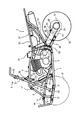
まず、車体全体の概略構造を説明する。図2及び図3に示すように、この車体フレームは、それぞれ予め小組された前部フレーム1と後部フレーム2とで構成されている。前部フレーム1は側面略視ループ状をなすように、メインフレーム3、フロントダウンフレーム4、ロアーフレーム5及びセンターフレーム6で構成され、それぞれは左右一対で設けられ、エンジン7を支持している。
【0014】
メインフレーム3はエンジン7の上方を通って前後方向へ延びる部材であり、フロントダウンフレーム4はメインフレーム3の前端部から連続して前方へ斜め下がりに折れ曲がって延び、下端部がロアーフレーム5の上方へ斜めに配設されている補強メンバー8の前部へ溶接される。
【0015】
補強メンバー8と下方のロアーフレーム5の各前端部間は前部パイプ9で連結され、補強メンバー8とロアーフレーム5の各中間部間肉抜き穴は中間パイプ10で連結され、補強メンバー8の後端部はエンジン7の下方でロアーフレーム5の中間部へ直接溶接されている。
【0016】
補強メンバー8とロアーフレーム5の対応する位置には、それぞれ前後に間隔をもってダブルウィッシュボーン式サスペンションを構成するアッパーアーム及びロアーアーム(いずれも図示せず)の各連結ブラケット11,12が設けられ、前輪13が懸架されている。
【0017】
補強メンバー8とロアーフレーム5の各前端部にはバンパ14が連結され、メインフレーム3からフロントダウンフレーム4へ変わる屈曲部近傍にはフロントサスペンションの緩衝器(図示省略)の上端を支持するためのステー15が設けられている。
【0018】
さらにこのステー15の近傍部から補強メンバー8の中間パイプ10と連結する部分に向かって後方へ斜め下がりに補強パイプ16が設けられ、この補強パイプ16にオイルタンク17が支持されている(図3では図示省略)。
【0019】
オイルタンク17はエンジン7の前方に位置し、左右の補強パイプ16、補強メンバー8、ロアーフレーム5等により周囲を囲まれ、チューブ18でオイルクーラー19へ接続されている。オイルクーラ19はメインフレーム3のオイルタンク17上方部分に吊り下げ支持されている(同上)。
【0020】
メインフレーム3のオイルクーラー19近傍部にはステアリングシャフト用ステー20が設けられ、ここにステアリングシャフト21が回動自在に支持されている。ステアリングシャフト21の上端部にはハンドルバー22が取付けられ、ステアリングシャフト21の下端部はロアーフレーム5に設けられた軸受部23へ支持され、その近傍にタイロッド(図示省略)の一端が連結されている。
【0021】
ロアーフレーム5の後端部はエンジン7の下方を通って後方へ延び、エンジン7の後端部近傍で上方へ屈曲して、センターフレーム6へ連続している。センターフレーム6の下部前側にはピボットプレート24が溶接され、ここでピボット軸25によりリヤスイングアーム26の前端がセンターフレーム6へ揺動自在に連結されている。
【0022】
リヤスイングアーム26はピボット軸25から後方へ延び、後端部において中間部を支持する車軸27の左右両端に後輪28が支持されている。後輪28は同軸で設けられたドリブンスプロケット29とエンジン7のドライブスプロケット30の間に巻き掛けされたチェーン31により駆動される。リヤスイングアーム26と前部フレーム1の間には後輪サスペンション用の緩衝器32が設けられている。
【0023】
後部フレーム2は、シートを支持するため、メインフレーム3の後端部から左右一対で後方へ延出するシートレール33と、その後部とセンターフレーム6の下部とを斜めに連結する左右一対のリヤステー34で構成されている。図中の符号35は排気管、36は気化器、37はマフラーである。
【0024】
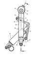
次に、リヤスイングアーム26の詳細構造を説明する。リヤスイングアーム26の側面形状を緩衝器32とともに示した図4に明らかなように、リヤスイングアーム26は、前端部にピボット軸25で支持されるピボット部40、後端部に車軸27を支持する車軸ホルダ41、及びこれらを前後に連結するアーム部42を備える。
【0025】
アーム部42の後部上面には、リンクステー43が設けられ、ここに一端を軸着された後部リンク44の前端が前部リンク45の後端部へ軸着されている。前部リンク45の前端部は車体側へ軸着されるとともに、その中間部に後述する肉抜き穴を通過した緩衝器32の下端部が軸着されている。
【0026】
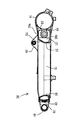
図1及び図5乃至図8に示すように、リヤスイングアーム26はアルミ合金を鋳造することにより、全体を一体かつ中空に形成したものであり、中央部の肉抜き穴46を囲んで、前部側の前側クロス部47、後部側の後側クロス部48及び左右両側の前記アーム部42で構成されている。
【0027】
肉抜き穴46は、平面視で略卵形をなして上下方向へ貫通する開口部であり、その周壁を構成する前部壁50、内側壁51及び後部壁52は滑らかに連続する曲線で構成され、各部のアールは一様であって、これらのアールを、前部壁50がR1、内側壁51がR2及び後部壁52がR3として示せば、R2>R1>R3の関係になっている。
【0028】
但し、後部壁52は一様なアールではなく、中央部分で、左右のリンクステー43をつなぐ部分は略直線状をなしている。したがって、本実施例において後部壁52のR3なるアール部分は、この略直線状よりも前方側の部分を指称するものとし、この部分のアール(R3)は内側壁51のアール(R2)と滑らかに接続している。
【0029】
なお、上記略直線状部分から左右のリンクステー43と平行にその下方を後方へ延出する左右一対の補強部リブ53が形成され、リヤスイングアーム26の上面26aと下面26bを連結して左右のリンクステー43を補強している(図8)。また、上記略直線状部分の後部壁52上部は、左右のリンクステー43間を斜め上がりに後方へ延びる斜面部54をなし、後部リンク44の逃げ部をなしている。
【0030】
これら各部のアール(R1、R2及びR3)は、それぞれ一様なアールで構成され、R1とR2の接続部がアーム部42の前端部となり、肉抜き穴46の横幅最大部をなし、R2とR3の接続部がアーム部42の後端部となり、この部分の肉抜き穴46の横幅は前記最大幅と比べて著しく小さくなっている。
【0031】
アーム部42は前側クロス部47と後側クロス部48を前後に連結するとともに、内側壁51及び外側壁49並びにリヤスイングアーム26の上面26aと下面26bとにより中空状に形成される(図7)。
【0032】
左右のアーム部42は車体中心を挟んで左右対称に形成され、かつ内側壁51が一様なアールであるため、横幅は前端部から後端部へ向かって徐々に広がるよう連続的に変化し、前端部の横幅(W1)が最小になり、後端部の横幅(W2)が最大になっている(図1)。
【0033】
また、アーム部42の側面における上下方向の幅は前後方向においてほぼ一定しているから、結局、アーム部42の断面積が前方から後方へ向かって連続的に拡大変化することになる。
【0034】
前側クロス部47は、リヤスイングアーム26の前端部において左右のアーム部42の各前端部間を連結する部分であり、中空に形成されるとともに、その前端部左右には、ピボット部40が前方へ突出して一体に形成されている。
【0035】
このピボット部40はピボット軸25に対する軸受けベアリングを嵌合するための部分である。左右のピボット部40を連結する前側クロス部47の前面部60は後方へ向かってV字形に突出する傾斜面をなし、その左右各傾斜面に前後方向へ貫通する砂抜き穴61が形成されている。
【0036】
後側クロス部48は、左右のアーム部42の各後端部間を連結して中空に形成されるとともに、その後端部に車軸ホルダ41を一体に形成してあり、この車軸ホルダ41は略円筒形に左右方向へ後側クロス部48を貫通して形成され、この中に偏心アジャスタ62が回転自在に保持され、これを介して車軸27が前後方向位置を調節自在に支持されるようになっている。
【0037】
図1に明らかなように、車軸ホルダ41を構成する前側の隔壁63は車体中心部分に砂抜き穴64が形成され、この砂抜き穴64を介して後側クロス部48の車軸ホルダ41より前方部分及びアーム部42の各内部空間と連通するとともに、車軸ホルダ41が左右へ開放された空間をなしているので、結局これら各空間は砂抜き穴64を介して外部へ連通した開放空間になっている。
【0038】
なお、左右のアーム部42の内部空間は前側クロス部47の内部空間と連通しているが、前側クロス部47の内部空間は、傾斜面に設けられている砂抜き穴61を介して直接外部へ開放されている。
【0039】
次に、本実施例の作用を説明する。このリヤスイングアーム26は肉抜き穴46を平面視略卵型に形成し、その内側壁51を連続するアールで形成したため、左右のアーム部42の横幅が、前側クロス部47の接続部である前端部(最小横幅W1)から後部壁52近傍の後端部(最大横幅W2)に向って次第に広くなっている。
【0040】
このため、アーム部42の剛性は前側クロス部47の接続部から車軸ホルダ41との接続部に向って次第に大きくなるよう連続的に変化し、この変化はアーム部42における前後方向各部に対して実際に要求される剛性の分布に即したものになっている。
【0041】
したがって、4輪バギー車のリヤスイングアーム26においては、高いねじれ剛性が要求されるが、各部毎に剛性を必要かつ十分にすることができ、その結果、余分な肉部を残して重量を増加させるようなことがないので、全体としての必要な剛性を確保しつつ軽量化を実現できる。
【0042】
また、アーム部42において、アールがR2なる内側壁51の前後を、同R1なる前部壁50のR1と同R3なる後部壁52へ連続アールで滑らかに接続したので、接続部への応力の集中を避けて要求される剛性を低くすることができ、この点でも軽量化に貢献できる。このような効果は、特に、高い剛性が要求されて重量が増加しやすい4輪バギー車のリヤスイングアーム26に好適である。
【0043】
さらに、リヤスイングアーム26を鋳造で成形したとき、成形に使用した砂型の砂は、前後の砂抜き穴61、64から排出される。このとき、内側壁51が連続アールで滑らかに変化しているので、比較的狭い空間である車軸ホルダ41内に、砂抜きに際して支障となる凹凸部や角部が形成されず、内部の砂をスムーズに排出できるので、リヤスイングアーム26の鋳造による成形効率が向上する。
【0044】
なお、本願発明は上記実施例に限定されず、種々に変形可能であり、例えば、前部壁50及び後部壁52は必ずしもアール形状でなく、直線状に形成することもできる。また、4輪バギー車用のみならず、自動2輪車用にも使用できる。
【図面の簡単な説明】
【図1】実施例に係るリヤスイングアームの平断面図
【図2】車体要部の全体側面図
【図3】その平断面図
【図4】リヤスイングアームの側面図
【図5】リヤスイングアームの平断面図
【図6】図5の6−6線断面図
【図7】図5の7−7線断面図
【図8】図5の8−8線断面図
1:前部小組体、2:後部小組体、3:メインフレーム、6:センターフレーム、7:エンジン、17:オイルタンク、26:リヤスイングアーム、27:車軸、28:後輪、32:リヤクッション、40:ピボット部、41:車軸ホルダ、42:アーム部、46:肉抜き穴、47:前側クロス部、48:後側クロス部、50:前部壁、51:内側壁、52:後部壁[0001]
BACKGROUND OF THE INVENTION
The present invention relates to a structure of a rear swing arm used in a saddle-ride type vehicle such as a four-wheel buggy.
[0002]
[Prior art]
No. 6-316 shows a rear swing arm of a four-wheel buggy. This rear swing arm has a front cross portion and a rear cross portion that are formed by casting or the like and connected by welding with a pair of left and right arms, and the arm portion has a pipe shape formed by extrusion or the like. A hollow hole having a substantially hexagonal shape in plan view is formed in a central portion surrounded by these members.
[0003]
[Problems to be solved by the invention]
In general, in the case of a four-wheel buggy vehicle, the rear swing arm supports the left and right rear wheels via an axle that crosses the rear end portion to the left and right, so that a large torsional rigidity is required. However, the required degree of rigidity is not uniform in each part in the front-rear direction, but is the highest in the vicinity of the front and rear cross parts, and gradually decreases in the intermediate part as the distance from the cross part increases.
[0004]
On the other hand, when the pipe member is provided in the arm portion as in the conventional example, it is impossible to cope with such a required change in rigidity, and the rigidity as a whole is inevitably higher than necessary. In addition, since the welding length becomes long when assembled by welding, the cost is likely to increase. In particular, when a reinforcing patch is provided, the welding length is further increased and the weight must be increased.
[0005]
In addition, when the shape of the hollow hole is a hexagonal shape such as a hexagon, the above-described problem becomes more prominent because reinforcement with the patch is indispensable to cope with stress concentration. An object of the present invention is to provide a rear swing arm for a saddle-ride type vehicle that solves such problems and is easy to manufacture.
[0006]
[Means for Solving the Problems]
In order to solve the above problems, the structure of the rear swing arm for a saddle-ride type vehicle according to the present invention is a rear swing for a saddle-ride type vehicle in which a front end portion is rotatably supported by a vehicle body frame and a rear end portion supports a rear wheel. In the structure of the arm,
The rear swing arm is made of a light alloy and is formed integrally and hollow by casting. The rear swing arm is provided with a lightening space inside thereof, and the left and right of the periphery of the lightening space are smoothly continuous. It is characterized by comprising a curve that changes to.
[0007]
Here, the lateral width means the width in the left-right direction (vehicle width direction) in a plan view state. The rear swing arm can also be applied to a four-wheel buggy vehicle.
[0008]
【The invention's effect】
The rear swing arm was entirely formed by casting using a light alloy, and was provided with a lightening space inside, and was configured with a curve that smoothly and continuously changed from side to side of the lightening space.
[0009]
For this reason, it can contribute to weight reduction, ensuring the rigidity requested | required avoiding concentration of stress. In addition, the cross-sectional area of the arm part of the rear swing arm can be changed according to the distribution of rigidity that is actually required, making it easy to change the cross-sectional area that was difficult with pipe members such as conventional extrusion molding. Can be realized.
[0010]
In addition, it is possible to realize the rigidity corresponding to the required one for each part in the front-rear direction of the arm part, and it is possible to realize an appropriate rigidity that satisfies the required torsional rigidity as a whole and to realize a sufficient weight reduction.
[0011]
Further, since the whole is formed integrally and hollow by casting, the welding operation as in the conventional example in which the front and rear cross portions and the left and right arm portions are formed separately and these are integrated by welding becomes unnecessary. Moreover, sand removal when forming the arm portion hollow can be facilitated by configuring the periphery of the lightening space with a curve that smoothly and continuously changes. As a result, the rear swing arm can be easily manufactured and the moldability can be improved.
[0012]
DETAILED DESCRIPTION OF THE INVENTION
An embodiment of the present invention applied to a four-wheel buggy vehicle will be described based on the drawings. 1 is a cross-sectional plan view of the rear swing arm (cross-sectional view taken along line 1-1 of FIG. 4), FIG. 2 is an overall side view of the main part of the vehicle body, FIG. 3 is a plan view thereof, and FIG. Figure 5 is a plan view of a rear swing arm, FIG. 6 is a vertical sectional view thereof, FIG. 7 is cross-sectional view taken along line 7-7 of FIG. 5, FIG. 8 is a cross-sectional view taken along line 8-8 in FIG.
[0013]
First, the schematic structure of the entire vehicle body will be described. As shown in FIGS. 2 and 3, the vehicle body frame includes a
[0014]
The
[0015]
The front end of the reinforcing member 8 and the lower lower frame 5 are connected by a front pipe 9, and the hollow holes between the intermediate portions of the reinforcing member 8 and the lower frame 5 are connected by an
[0016]
At the corresponding positions of the reinforcing member 8 and the lower frame 5, there are provided connecting
[0017]
[0018]
Further, a
[0019]
The
[0020]
A steering
[0021]
The rear end portion of the lower frame 5 extends rearward through the lower side of the
[0022]
The
[0023]
In order to support the seat, the rear frame 2 has a pair of left and right rear stays that obliquely connect the rear portion and the lower portion of the
[0024]
Next, the detailed structure of the
[0025]
A
[0026]
As shown in FIGS. 1 and 5 to 8, the
[0027]
The lightening
[0028]
However, the
[0029]
A pair of left and right reinforcing
[0030]
The rounds (R1, R2 and R3) of these parts are each configured with a uniform round, and the connecting part of R1 and R2 becomes the front end part of the
[0031]
The
[0032]
Since the left and
[0033]
Further, since the vertical width of the side surface of the
[0034]
The
[0035]
The
[0036]
The
[0037]
As apparent from FIG. 1, the
[0038]
Note that the internal space of the left and
[0039]
Next, the operation of this embodiment will be described. In this
[0040]
For this reason, the rigidity of the
[0041]
Therefore, in the
[0042]
The
[0043]
Furthermore, when the
[0044]
In addition, this invention is not limited to the said Example, It can deform | transform variously, for example, the
[Brief description of the drawings]
FIG. 1 is a cross-sectional view of a rear swing arm according to an embodiment. FIG. 2 is a side view of the entire vehicle body. FIG. 3 is a cross-sectional view of the main body. cross-sectional plan view of the
Claims (8)
前記リヤスイングアームは軽合金を用いて全体が鋳造により一体かつ中空に形成されるものであって、
その内部に肉抜き空間を設けるとともに、当該肉抜き空間の周囲のうち左右は滑らかに連続的に変化する曲線で構成されることを特徴とする鞍乗り型車両用リヤスイングアームの構造。In the structure of a rear swing arm for a saddle-ride type vehicle in which a front end portion is rotatably supported on a vehicle body frame and a rear end portion supports a rear wheel,
The rear swing arm is formed integrally and hollow by casting using a light alloy,
A structure of a rear swing arm for a saddle-ride type vehicle, characterized in that a lightening space is provided therein, and the left and right sides of the periphery of the lightening space are configured with curves that change smoothly and continuously.
Priority Applications (2)
| Application Number | Priority Date | Filing Date | Title |
|---|---|---|---|
| JP27863898A JP3585378B2 (en) | 1998-09-30 | 1998-09-30 | Rear swing arm structure for saddle-ride type vehicles |
| US09/392,576 US6206398B1 (en) | 1998-09-30 | 1999-09-09 | Structure of a rear swingarm for a vehicle with saddle seat |
Applications Claiming Priority (1)
| Application Number | Priority Date | Filing Date | Title |
|---|---|---|---|
| JP27863898A JP3585378B2 (en) | 1998-09-30 | 1998-09-30 | Rear swing arm structure for saddle-ride type vehicles |
Publications (3)
| Publication Number | Publication Date |
|---|---|
| JP2000108975A JP2000108975A (en) | 2000-04-18 |
| JP3585378B2 true JP3585378B2 (en) | 2004-11-04 |
| JP2000108975A5 JP2000108975A5 (en) | 2005-02-17 |
Family
ID=17600076
Family Applications (1)
| Application Number | Title | Priority Date | Filing Date |
|---|---|---|---|
| JP27863898A Expired - Fee Related JP3585378B2 (en) | 1998-09-30 | 1998-09-30 | Rear swing arm structure for saddle-ride type vehicles |
Country Status (2)
| Country | Link |
|---|---|
| US (1) | US6206398B1 (en) |
| JP (1) | JP3585378B2 (en) |
Families Citing this family (19)
| Publication number | Priority date | Publication date | Assignee | Title |
|---|---|---|---|---|
| JP4364362B2 (en) * | 1999-09-05 | 2009-11-18 | 本田技研工業株式会社 | Motorcycle frame structure |
| US20040035626A1 (en) * | 2002-02-22 | 2004-02-26 | Bruno Girouard | Vehicle and adjustable steering shaft therefor |
| US20040129483A1 (en) * | 2001-06-11 | 2004-07-08 | Bruno Girouard | Vehicle and adjustable steering shaft therefor |
| US6860353B2 (en) * | 2001-06-20 | 2005-03-01 | Yamaha Hatsudoki Kabushiki Kaisha | Motorcycle rear suspension swingarm assembly |
| US20030221891A1 (en) * | 2002-02-22 | 2003-12-04 | Berthold Fecteau | Three-wheeled vehicle with a fender assembly and lighting system therefor |
| US6948581B2 (en) * | 2002-02-22 | 2005-09-27 | Bombardier Recreational Products Inc | Three-wheel vehicle and concentric intermediate sprocket assembly therefor |
| US20040035625A1 (en) * | 2002-02-22 | 2004-02-26 | Jean-Guy Talbot | Ergonomic arrangement for a three-wheeled vehicle |
| US20040035623A1 (en) * | 2002-02-22 | 2004-02-26 | Berthold Fecteau | Frame configuration for a three-wheel vehicle |
| EP1476679A1 (en) * | 2002-02-22 | 2004-11-17 | Bombardier Recreational Products Inc. | Three-wheeled vehicle with a continuously variable transmission |
| US20040129473A1 (en) * | 2002-02-22 | 2004-07-08 | Jean-Guy Talbot | Ergonomic arrangement for a three-wheeled vehicle |
| US20040032120A1 (en) * | 2002-02-22 | 2004-02-19 | Esa Vaisanen | Progressive steering system |
| JP2004314939A (en) * | 2003-04-04 | 2004-11-11 | Honda Motor Co Ltd | Frame structure of saddle riding type vehicle, and frame manufacturing method |
| JP2005001509A (en) * | 2003-06-11 | 2005-01-06 | Yamaha Motor Co Ltd | Rear suspension in saddle-riding type vehicle |
| CA2496491C (en) * | 2004-02-13 | 2009-07-21 | Honda Motor Co., Ltd. | Vehicle body frame structure for all-terrain vehicle |
| JP4558432B2 (en) * | 2004-09-30 | 2010-10-06 | 本田技研工業株式会社 | Swing arm structure |
| US7837000B2 (en) | 2007-07-13 | 2010-11-23 | Yamaha Hatsudoki Kabushiki Kaisha | All terrain vehicle with drive-chain tension adjuster |
| JP5618949B2 (en) * | 2011-08-29 | 2014-11-05 | 本田技研工業株式会社 | Swing arm for small vehicle |
| CN107415612B (en) * | 2016-05-24 | 2023-11-17 | 上汽通用五菱汽车股份有限公司 | Reinforced swing arm installing support |
| CN107757711B (en) * | 2017-11-15 | 2023-07-28 | 浙江春风动力股份有限公司 | Vehicle frame |
Family Cites Families (7)
| Publication number | Priority date | Publication date | Assignee | Title |
|---|---|---|---|---|
| US4775025A (en) * | 1986-12-05 | 1988-10-04 | James Parker | Motorcycle with ride height suspension adjustment |
| JPH06316Y2 (en) | 1987-05-22 | 1994-01-05 | 本田技研工業株式会社 | Swing arm |
| JPH02286486A (en) * | 1989-04-28 | 1990-11-26 | Yamaha Motor Co Ltd | Rear arm for motorcycle |
| JPH0342392A (en) * | 1989-07-07 | 1991-02-22 | Suzuki Motor Corp | Rear fork for bicycle |
| JPH04243679A (en) * | 1991-01-21 | 1992-08-31 | Suzuki Motor Corp | Axle metal fitting for rear fork of motorcycle |
| US5452911A (en) * | 1993-08-13 | 1995-09-26 | Klein Bicycle Corporation | High efficiency high clearance chinstay and method of making same for bicycles |
| US5476278A (en) * | 1994-07-14 | 1995-12-19 | Schwinn Cycling & Fitness Inc. | Seat stays for a bicycle frame |
-
1998
- 1998-09-30 JP JP27863898A patent/JP3585378B2/en not_active Expired - Fee Related
-
1999
- 1999-09-09 US US09/392,576 patent/US6206398B1/en not_active Expired - Lifetime
Also Published As
| Publication number | Publication date |
|---|---|
| JP2000108975A (en) | 2000-04-18 |
| US6206398B1 (en) | 2001-03-27 |
Similar Documents
| Publication | Publication Date | Title |
|---|---|---|
| JP3585378B2 (en) | Rear swing arm structure for saddle-ride type vehicles | |
| JP3816210B2 (en) | Body structure of a low-floor motorcycle | |
| JP3869122B2 (en) | Body frame structure of 4-wheel buggy car | |
| EP1462351B1 (en) | Motorcycle | |
| JP4708061B2 (en) | Body frame structure | |
| EP1138588B1 (en) | A motorcycle frame | |
| JP3990551B2 (en) | Motorcycle frame structure | |
| JP4853900B2 (en) | Body frame structure for motorcycles | |
| US6371236B1 (en) | Vehicle frame structure of motorcycle | |
| JP5014858B2 (en) | Body frame structure | |
| US7644800B2 (en) | Motorcycle exhaust structure | |
| US7762587B2 (en) | Body frame structure of straddle-type four wheeled vehicle | |
| JP4786947B2 (en) | Motorcycle body structure | |
| JP4426352B2 (en) | Motorcycle frame | |
| US6264241B1 (en) | Frame structure for saddling type vehicle | |
| JP4405001B2 (en) | Engine support structure for motorcycles | |
| EP1762479B1 (en) | Two-wheeled motor vehicle | |
| JPH026670B2 (en) | ||
| JPH0471748B2 (en) | ||
| JP4247839B2 (en) | Motorcycle body structure | |
| JP3825153B2 (en) | Cradle type motorcycle body frame | |
| WO2014069037A1 (en) | Frame structure for saddle-type vehicle | |
| JP4727315B2 (en) | Motorcycle body structure | |
| JP2951365B2 (en) | Motorcycle swing arm | |
| JP4739537B2 (en) | Cast motorcycle rear arm |
Legal Events
| Date | Code | Title | Description |
|---|---|---|---|
| A521 | Written amendment |
Free format text: JAPANESE INTERMEDIATE CODE: A523 Effective date: 20040310 |
|
| A621 | Written request for application examination |
Free format text: JAPANESE INTERMEDIATE CODE: A621 Effective date: 20040310 |
|
| A871 | Explanation of circumstances concerning accelerated examination |
Free format text: JAPANESE INTERMEDIATE CODE: A871 Effective date: 20040310 |
|
| A131 | Notification of reasons for refusal |
Free format text: JAPANESE INTERMEDIATE CODE: A131 Effective date: 20040427 |
|
| A521 | Written amendment |
Free format text: JAPANESE INTERMEDIATE CODE: A523 Effective date: 20040625 |
|
| TRDD | Decision of grant or rejection written | ||
| A01 | Written decision to grant a patent or to grant a registration (utility model) |
Free format text: JAPANESE INTERMEDIATE CODE: A01 Effective date: 20040803 |
|
| A61 | First payment of annual fees (during grant procedure) |
Free format text: JAPANESE INTERMEDIATE CODE: A61 Effective date: 20040803 |
|
| R150 | Certificate of patent or registration of utility model |
Free format text: JAPANESE INTERMEDIATE CODE: R150 |
|
| FPAY | Renewal fee payment (event date is renewal date of database) |
Free format text: PAYMENT UNTIL: 20080813 Year of fee payment: 4 |
|
| FPAY | Renewal fee payment (event date is renewal date of database) |
Free format text: PAYMENT UNTIL: 20090813 Year of fee payment: 5 |
|
| FPAY | Renewal fee payment (event date is renewal date of database) |
Free format text: PAYMENT UNTIL: 20100813 Year of fee payment: 6 |
|
| FPAY | Renewal fee payment (event date is renewal date of database) |
Free format text: PAYMENT UNTIL: 20100813 Year of fee payment: 6 |
|
| FPAY | Renewal fee payment (event date is renewal date of database) |
Free format text: PAYMENT UNTIL: 20110813 Year of fee payment: 7 |
|
| FPAY | Renewal fee payment (event date is renewal date of database) |
Free format text: PAYMENT UNTIL: 20110813 Year of fee payment: 7 |
|
| FPAY | Renewal fee payment (event date is renewal date of database) |
Free format text: PAYMENT UNTIL: 20120813 Year of fee payment: 8 |
|
| FPAY | Renewal fee payment (event date is renewal date of database) |
Free format text: PAYMENT UNTIL: 20120813 Year of fee payment: 8 |
|
| FPAY | Renewal fee payment (event date is renewal date of database) |
Free format text: PAYMENT UNTIL: 20130813 Year of fee payment: 9 |
|
| FPAY | Renewal fee payment (event date is renewal date of database) |
Free format text: PAYMENT UNTIL: 20140813 Year of fee payment: 10 |
|
| LAPS | Cancellation because of no payment of annual fees |