JP3811339B2 - Endoscope system - Google Patents
Endoscope system Download PDFInfo
- Publication number
- JP3811339B2 JP3811339B2 JP2000238992A JP2000238992A JP3811339B2 JP 3811339 B2 JP3811339 B2 JP 3811339B2 JP 2000238992 A JP2000238992 A JP 2000238992A JP 2000238992 A JP2000238992 A JP 2000238992A JP 3811339 B2 JP3811339 B2 JP 3811339B2
- Authority
- JP
- Japan
- Prior art keywords
- endoscope
- temperature
- insertion portion
- cooling
- sterilization
- Prior art date
- Legal status (The legal status is an assumption and is not a legal conclusion. Google has not performed a legal analysis and makes no representation as to the accuracy of the status listed.)
- Expired - Fee Related
Links
- 238000003780 insertion Methods 0.000 claims description 88
- 230000037431 insertion Effects 0.000 claims description 88
- 238000001514 detection method Methods 0.000 claims description 23
- 238000005452 bending Methods 0.000 claims description 20
- 238000005259 measurement Methods 0.000 claims description 7
- 238000004659 sterilization and disinfection Methods 0.000 description 87
- 230000001954 sterilising effect Effects 0.000 description 86
- 238000001816 cooling Methods 0.000 description 85
- 238000000034 method Methods 0.000 description 32
- 230000008569 process Effects 0.000 description 32
- 238000003860 storage Methods 0.000 description 32
- 238000010586 diagram Methods 0.000 description 23
- 239000002826 coolant Substances 0.000 description 16
- 238000007689 inspection Methods 0.000 description 15
- 239000007788 liquid Substances 0.000 description 14
- 239000000463 material Substances 0.000 description 14
- 238000011282 treatment Methods 0.000 description 13
- XLYOFNOQVPJJNP-UHFFFAOYSA-N water Substances O XLYOFNOQVPJJNP-UHFFFAOYSA-N 0.000 description 9
- 230000001105 regulatory effect Effects 0.000 description 8
- 238000001035 drying Methods 0.000 description 7
- 238000001444 catalytic combustion detection Methods 0.000 description 6
- 239000000498 cooling water Substances 0.000 description 6
- 230000000694 effects Effects 0.000 description 6
- 238000003384 imaging method Methods 0.000 description 6
- 238000001839 endoscopy Methods 0.000 description 5
- 239000011347 resin Substances 0.000 description 5
- 229920005989 resin Polymers 0.000 description 5
- 238000009529 body temperature measurement Methods 0.000 description 4
- 238000005286 illumination Methods 0.000 description 4
- 230000002265 prevention Effects 0.000 description 3
- 230000005855 radiation Effects 0.000 description 3
- 230000009471 action Effects 0.000 description 2
- 229910052782 aluminium Inorganic materials 0.000 description 2
- XAGFODPZIPBFFR-UHFFFAOYSA-N aluminium Chemical compound [Al] XAGFODPZIPBFFR-UHFFFAOYSA-N 0.000 description 2
- 238000004891 communication Methods 0.000 description 2
- 239000000110 cooling liquid Substances 0.000 description 2
- 230000006837 decompression Effects 0.000 description 2
- 230000007423 decrease Effects 0.000 description 2
- 238000002360 preparation method Methods 0.000 description 2
- 238000009423 ventilation Methods 0.000 description 2
- 230000037303 wrinkles Effects 0.000 description 2
- 229910000838 Al alloy Inorganic materials 0.000 description 1
- 239000004698 Polyethylene Substances 0.000 description 1
- 230000033228 biological regulation Effects 0.000 description 1
- 230000036760 body temperature Effects 0.000 description 1
- 238000004140 cleaning Methods 0.000 description 1
- 230000001276 controlling effect Effects 0.000 description 1
- 238000011161 development Methods 0.000 description 1
- 230000005611 electricity Effects 0.000 description 1
- 229920001973 fluoroelastomer Polymers 0.000 description 1
- 230000005484 gravity Effects 0.000 description 1
- 208000015181 infectious disease Diseases 0.000 description 1
- 238000002347 injection Methods 0.000 description 1
- 239000007924 injection Substances 0.000 description 1
- 238000012423 maintenance Methods 0.000 description 1
- 230000007246 mechanism Effects 0.000 description 1
- 229910052751 metal Inorganic materials 0.000 description 1
- 239000002184 metal Substances 0.000 description 1
- 239000000203 mixture Substances 0.000 description 1
- 238000012986 modification Methods 0.000 description 1
- 230000004048 modification Effects 0.000 description 1
- 210000000056 organ Anatomy 0.000 description 1
- -1 polyethylene Polymers 0.000 description 1
- 229920000573 polyethylene Polymers 0.000 description 1
- 239000002861 polymer material Substances 0.000 description 1
- 239000011148 porous material Substances 0.000 description 1
- 238000012545 processing Methods 0.000 description 1
- 230000001737 promoting effect Effects 0.000 description 1
- 238000011946 reduction process Methods 0.000 description 1
- 238000007789 sealing Methods 0.000 description 1
- 229920002379 silicone rubber Polymers 0.000 description 1
- 239000007779 soft material Substances 0.000 description 1
- 238000012360 testing method Methods 0.000 description 1
- 238000005406 washing Methods 0.000 description 1
Images


Description
【0001】
【発明の属する技術分野】
本発明は、使用後の滅菌処理を高圧蒸気滅菌によって行う内視鏡を有する内視鏡システムに関する。
【0002】
【従来の技術】
従来より、細長の挿入部を体腔内に挿入することにより、体腔内臓器などを観察したり、必要に応じて処置具チャンネル内に挿通した処置具を用いて各種治療処置の行える医療用の内視鏡が広く利用されている。
【0003】
特に、医療分野で使用される内視鏡は、挿入部を体腔内に挿入して、臓器などを観察したり、内視鏡の処置具チャンネル内に挿入した処置具を用いて、各種治療や処置を行う。
【0004】
このため、一度使用した内視鏡や処置具を他の患者に再使用する場合、内視鏡や処置具を介しての患者間感染を防止する必要から、検査・処置終了後に内視鏡装置の洗滌消毒を行わなければならなかった。
【0005】
近年では、煩雑な作業を伴わず、滅菌後直ちに使用が可能で、ランニングコストが安価なオートクレーブ滅菌(高圧蒸気滅菌)が医療機器の消毒滅菌処理の主流になりつつある。
【0006】
例えば、特開平5−337171号公報には医療機器が収納されるオートクレーブ装置本体の温度及び前記医療機器の温度を検出する温度検出手段を有し、前記温度検出手段の出力が前記医療機器の使用が可能となる基準の温度以下に下がらない場合には扉を開くのを禁止する扉ロック/アンロック機構を設けたオートクレーブ装置が示されている。
【0007】
【発明が解決しようとする課題】
しかしながら、前記特開平5−337171号公報のオートクレーブ装置ではオートクレーブ装置内が滅菌工程時に130℃以上の高温高圧蒸気で満たされるため、温度検出手段の設置が難しく、オートクレーブ装置の構造が複雑になるという問題があった。
【0008】
そして、従来よりある既存のオートクレーブ装置によって内視鏡を高圧蒸気滅菌した場合については何ら考慮がなされていなかった。
【0009】
本発明は上記事情に鑑みてなされたものであり、特別なオートクレーブ装置が不要で、高圧蒸気滅菌後に内視鏡の温度が使用可能な状態であるか否かの確認を確実かつ容易に行える互換性に優れた内視鏡システムを提供することを目的にしている。
【0010】
【課題を解決するための手段】
本発明の内視鏡システムは、挿入部を備えた内視鏡と、所定の位置に配置された前記挿入部に向かって設けられ、挿入部先端側に設けられた湾曲部より先端側の外表面の温度を測定する温度検知手段と、この温度検知手段において測定した測定値を基に、前記内視鏡における挿入部の温度が使用可能な状態であるか否かを判断するための情報を告知する告知手段と、を具備することを特徴とする。
【0011】
この構成によれば、告知手段に告知された情報によって、術者は内視鏡の温度が使用可能な温度状態であるか否かの判断を容易に行える。
【0012】
【発明の実施の形態】
以下、図面を参照して本発明の実施の形態を説明する。
図1ないし図3は本発明の第1実施形態に係り、図1は内視鏡装置の概略構成を説明する図、図2はホワイトバランス調整に用いる温度測定装置付きホワイトバランスキャップを示す図、図3はホワイトバランスキャップの構成を説明する図である。
【0013】
図1に示すように本実施形態の内視鏡装置1は、撮像手段として例えばCCDを備えた電子内視鏡(以下内視鏡と記載する)2と、照明光を供給する光源装置3と、撮像手段を制御するとともに前記撮像手段から得られる信号を処理するビデオプロセッサ4と、このビデオプロセッサ4に接続されたモニタ5とで主に構成されている。なお、符号6は前記光源装置3、ビデオプロセッサ4、モニタ5等を載置するカートであり、このカート6の側部には撮像手段であるCCDの個体差による観察画像の色調のばらつきを補正するホワイトバランス調整を行うホワイトバランスキャップ21が取り付けられている。また符号50はこの内視鏡2を収納する後述する滅菌用収納ケースである。
【0014】
前記内視鏡2は、細長で可撓性を有する挿入部10と、この挿入部10の基端部に連設する操作部11と、この操作部11の側方から延出する可撓性を有するユニバーサルコード12とで構成されている。
【0015】
前記ユニバーサルコード12の端部には前記光源装置3に着脱自在なコネクタ12aが設けられている。このコネクタ12aを光源装置3に接続することによって、光源装置3に備えられている図示しないランプからの照明光が内視鏡2の図示しないライトガイドを伝送されて観察部位を照射するようになっている。
【0016】
前記挿入部10と操作部との接続部分には急激な曲がりを防止する弾性部材で構成された挿入部折れ止め部材7aが設けられ、前記操作部11とユニバーサルコード12との接続部分には同様に操作部折れ止め部材7bが設けられ、そしてユニバーサルコード12とコネクタ12aとの接続部分には同様にコネクタ部折れ止め部材7cが設けられている。
【0017】
前記内視鏡2の細長で可撓性を有する挿入部10は、先端側から順に硬性で例えば先端面に図示しない観察窓や照明窓などを配設した先端硬性部13,複数の湾曲駒を連接して湾曲自在な湾曲部14、微妙な柔軟性と弾発性とからなる可撓性を有する軟性部である可撓管部15とを連設して構成されている。前記湾曲部14は、操作部11に設けられている湾曲操作ノブ16を適宜操作することによって湾曲し、観察窓等を配設した先端硬性部13の先端面を所望の方向に向けられるようになっている。
【0018】
前記操作部11には前記湾曲操作ノブ16の他に先端面に設けた図示しない送気送水ノズルから前記観察窓に向けて洗滌液体や気体を噴出させる際の送気操作、送水操作を行う送気送水操作ボタン17及び先端面に設けた図示しない吸引口を介して吸引操作を行うための吸引操作ボタン18、前記ビデオプロセッサ4を遠隔操作する複数のリモートスイッチ19や内視鏡2の挿入部内に配置された処置具チャンネルに連通する処置具挿入口20が設けられている。
【0019】
前記コネクタ12aの側部には電気コネクタ部12bが設けられている。この電気コネクタ部12bには前記ビデオプロセッサ4に接続された信号ケーブル4aの信号コネクタ4bが着脱自在に接続される。この信号コネクタ4bを電気コネクタ部12bに接続することによって、内視鏡2の撮像手段を制御するとともに、この撮像手段から伝送される電気信号から映像信号を生成して、内視鏡観察画像を前記モニタ5の画面上に表示する。なお、電気コネクタ部12bには内視鏡2の内部と外部とを連通する図示しない通気口が設けられている。このため、前記内視鏡2の電気コネクタ部12bには前記通気口を塞ぐ圧力調整弁(不図示)を設けた後述する圧力調整弁付き防水キャップ(以下防水キャップと略記する)9aが着脱自在な構成になっている。
【0020】
また、このコネクタ12aには光源装置3に内蔵されている図示しない気体供給源に着脱自在に接続される気体供給口金12cや、液体供給源である送水タンク8に着脱自在に接続される送水タンク加圧口金12d及び液体供給口金12e、前記吸引口より吸引を行うための図示しない吸引源が接続される吸引口金12f、送水を行うための図示しない送水手段と接続される注入口金12gが設けられている。
【0021】
さらに、高周波処置等を行った際、内視鏡2に高周波漏れ電流が発生した場合、この漏れ電流を図示しない高周波処置装置に帰還させるためのアース端子口金12hが設けられている。
【0022】
前記内視鏡2は、観察や処置に使用された際、洗滌後、高圧蒸気滅菌を行うことが可能に構成されており、この内視鏡2を高圧蒸気滅菌する際には前記防水キャップ9aを電気コネクタ部12bに取り付ける。
【0023】
そして、前記内視鏡2を高圧蒸気滅菌する際、この内視鏡2を滅菌用収納ケース50に収納する。この滅菌用収納ケース50は、ケース本体であるトレイ51と蓋部材52とで構成され、このトレイ51には内視鏡2の挿入部10、操作部11、ユニバーサルコード12、コネクタ12a等の各部が所定の位置に収まるように内視鏡形状に対応した図示しない規制部材が配置されている。また、これらトレイ51及び蓋部材52には高圧蒸気を導くための通気孔が複数形成されている。
【0024】
前記内視鏡2に備えられている撮像手段であるCCDは個体差による観察画像の色調のばらつきがあり、これを補正するため、ホワイトバランス調整を行う必要がある。
【0025】
図2及び図3に示すように前記ホワイトバランスキャップ21は、固定部材6aによって前記カート6に一体的に取り付けられている。
前記ホワイトバランスキャップ21は、略筒状に形成した挿入部10の先端側が配置される凹部22aを有する筒状部22を備え、この筒状部22の底面にはホワイトバランス調整の際の基準色になる白色で形成した被写体部23が設けられている。この筒状部22の凹部22aの深さ寸法は、前記挿入部10の先端側から湾曲部14の一部までを収納することが可能であり、例えば30mmから100mm程度である。
【0026】
また、前記ホワイトバランスキャップ21の筒状部22の内面開口近傍には温度検知手段として1つ又は複数の赤外線温度センサ24が前記筒状部22の略中心軸方向に向かって配置されている。この赤外線温度センサ24には所定のデータ処理等を行うCPU等からなる制御部25が電気的に接続されており、この制御部25で処理された前記赤外線温度センサ24で測定された温度データのうち所定の温度データが情報を告知する告知手段である表示部26に出力されて表示されるようになっている。
【0027】
前記制御部25は、図示しないキャップ部電源スイッチをON状態にした測定開始直後より、例えば0.1sec の間隔で随時温度測定を行う一方、所定時間(例えば10秒間)毎に、測定した複数の温度データの中から最も高い温度である温度データを表示部26に表示させる制御を行う。そして、前記キャップ部電源スイッチがOFF状態に戻されるまで繰り返し前述した動作を行う。
【0028】
つまり、本実施形態のホワイトバランスキャップ21は、温度測定部及び温度表示部を有する内視鏡温度測定装置を備えたホワイトバランスキャップである。
【0029】
ここで、内視鏡2を高圧蒸気滅菌する際の代表的な条件について説明する。
この代表的な条件としては米国規格協会承認、医療機器開発協会発行の米国規格ANSI/AAMI ST37−1992に、プレバキュームタイプで滅菌工程132°Cで4分、グラビティタイプで滅菌工程132°Cで10分とされている。
【0030】
高圧蒸気滅菌の滅菌工程時の温度条件については、高圧蒸気滅菌装置の形式や滅菌工程の時間によって異なるが、一般的には115°Cから138°C程度の範囲で設定される。滅菌装置の中には142°C程度に設定可能なものもある。
【0031】
時間条件については滅菌工程の温度条件によって異なる。一般的には3〜60分程度に設定される。滅菌装置の種類によっては100分程度に設定可能なものもある。
【0032】
そして、この工程での滅菌装置内の圧力は一般的には大気圧に対して+0.2MPa程度に設定される。
【0033】
次に、一般的なプレバキュームタイプにおける内視鏡の高圧蒸気滅菌工程を簡単に説明する。
まず、滅菌対象機器である内視鏡2の電気コネクタ部12bには防水キャップ9aが取り付け、滅菌用収納ケース50に収容し、滅菌装置内に配置する。前記電気コネクタ部12bに防水キャップ9aを取り付けたことにより、圧力調整弁が閉じた状態になって前記通気口を塞ぐ。すなわち、内視鏡2の内部と外部とが水密的に密閉される。そして、高圧滅菌工程前の滅菌装置内を減圧状態(プレバキューム工程)にする。
【0034】
なお、このプレバキューム工程とは、滅菌工程時に滅菌対象機器の細部にまで蒸気を浸透させるための工程であり、滅菌装置内を減圧させることにより、滅菌対象機器全体に高圧高温蒸気が行き渡るようになる。このプレバキューム工程における滅菌装置内の圧力は、一般的に大気圧に対して−0.07〜−0.09MPa程度に設定される。
【0035】
しかし、プレバキューム工程において、滅菌装置内の圧力が減少すると、内視鏡2の内部圧力に対して外部圧力が低くなって圧力差が生じる。すると、前記防水キャップ9aの圧力調整弁が開いて、前記通気口を介して内視鏡2の内部と外部とが連通状態になる。このことによって、圧力差が大きく生じることを防ぐ。つまり、内視鏡2が内部圧力と外部圧力との圧力差によって破損することが防止される。
【0036】
次に、滅菌装置内に高圧高温蒸気を送り込んで滅菌を行う(滅菌工程)。
この滅菌工程においては滅菌装置内が加圧される。すると、内視鏡2の内部圧力より外部圧力の方が高くなるような圧力差が生じる。このため、前記防水キャップ9aの圧力調整弁が閉じ、高圧蒸気が通気口を通過して内視鏡内部に侵入することを遮断する。
【0037】
しかし、高圧蒸気は、高分子材料で形成されている前記可撓管15の外皮チューブ15cや内視鏡2の外装体の接続部に設けられたシール手段であるフッ素ゴムやシリコンゴム等で形成されたOリング等を透過して内視鏡内部に徐々に侵入していく。
【0038】
このとき、内視鏡2の外装体にはプレバキューム工程で減圧された圧力と滅菌工程で加圧された圧力とが加算された、外部から内部に向けた圧力が生じた状態になる。
【0039】
次いで、滅菌後の滅菌対象機器を乾燥させるため、滅菌工程終了後、滅菌装置内を再度減圧状態にして乾燥(乾燥工程)を行う。この乾燥工程では、滅菌装置内を減圧して滅菌装置内から蒸気を排除して滅菌装置内の滅菌対象機器の乾燥を促進する。この乾燥工程における滅菌装置内の圧力は一般的には大気圧に対して−0.07MPa〜−0.09MPa程度に設定される。なお、前記乾燥工程は必要に応じて任意に行うものである。
【0040】
滅菌工程後の減圧工程では、滅菌装置内の圧力が減少して内視鏡2の内部圧力より外部圧力が低くなるような圧力差が生じる。この圧力差が生じると略同時に前記防水キャップ9aの圧力調整弁が開き、通気口を介して内視鏡2の内部と外部とが連通状態になり、内視鏡内部と外部との間に大きな圧力差が生じることが防止される。そして、内視鏡2の内部圧力と外部圧力と略等しくなると前記防水キャップ9aの圧力調整弁が閉じる。そして、減圧工程が終了し、装置内は大気圧となる。
【0041】
なお、高圧蒸気滅菌全工程終了時、内視鏡2の外装体には減圧工程で減圧された分、外部から内部に向けた圧力が生じた状態になる。そして、防水キャップ9aを電気コネクタ部12bから取り外すことにより、前記通気口によって内視鏡2の内部と外部とが連通して、内視鏡2の内部は大気圧となり、内視鏡2の外装体に生じていた圧力差による負荷がなくなる。
【0042】
上述したように滅菌工程中、内視鏡2の内部及び外部は高圧蒸気にさらされるので、前記滅菌装置内より取り出す際の温度は、冷却工程のない高圧蒸気滅菌装置の場合では、一般的に80℃〜130℃程度である。
【0043】
高圧蒸気滅菌済みの内視鏡2を使用するに当たって、まず、検査前にホワイトバランス調整を行う。そのため、前記キャップ部電源スイッチをON状態にする。そして、前記内視鏡2の挿入部10先端側をホワイトバランスキャップ21の凹部22a内に挿入させて、この挿入部10の先端面を被写体部23に当接させ、被写体部23を撮像しながらホワイトバランス調整を行う。
【0044】
この挿入状態及びホワイトバランス調整状態のとき、前記ホワイトバランスキャップ21に設けられている赤外線温度センサ24は、凹部22a内に挿入されてくる先端硬性部13から湾曲部14までの外表面の温度を測定する。そして、この赤外線温度センサ24で測定された温度データを、制御部25で所定の処理を行い、表示部26に温度を表示させる。
【0045】
このとき、前記表示部26に表示された温度が例えば40℃以上である場合には、検査を始めずに前記内視鏡2の冷却を行う。一方、前記表示温度が40℃以下の場合には内視鏡検査可能な状態であると判断して、ホワイトバランス調整完了後内視鏡検査を開始する。
【0046】
なお、前記表示温度が40℃のとき、この40℃が体温と略同等の温度であるので、内視鏡検査の際、被検者がほとんど違和感を感じない温度である。つまり、この温度を内視鏡検査を行うか否かを判断する基準温度にしている。
【0047】
このように、内視鏡検査前に必ず使用されるホワイトバランス調整用のホワイトバランスキャップに赤外線温度センサ等の温度検知手段を設け、この赤外線温度センサで測定した結果を表示部に表示させることによって、通常のホワイトバランス調整作業と略同様の作業で内視鏡の挿入部の温度の確認を確実に行うことができる。このことによって、高圧蒸気滅菌後の内視鏡の温度が使用可能な状態であるか否かの確認を容易に行える。
【0048】
また、内視鏡の挿入部の先端面をホワイトバランス調整のために被写体部に当接させているので、確実に所定位置までの温度測定を行うことができる。
【0049】
このことによって、ホワイトバランス調整の際、通常、作業者は可撓管部を把持するので、この可撓管部の温度の認識を手で直接的に行える一方、通常検査開始まで作業者が触れない湾曲部より先端側の温度を表示部にて確認して作業者は挿入部全体の温度の把握を行える。
【0050】
さらに、温度検知手段として測定対象物に対して非接触で測定可能な赤外線温度センサを用いたことによって、接触状態等によって生じる測定温度のばらつきをなくして正確な温度測定を行うことができる。
【0051】
なお、本実施形態においては、内視鏡2に温度を検知するための特別な構成が不要であるとともに、光源装置3、ビデオプロセッサ4、モニタ5等の外部装置にも温度検知のための特別な構成が不要である。つまり、内視鏡及び外部装置に既存のものが使用可能である。また、前記制御部25では赤外線温度センサ24で所定の間隔で温度を随時測定させる一方、所定時間内で測定した温度データの中から最も高い温度データを表示部26に表示させる制御を行うようにさせているが、赤外線温度センサ24で測定した温度をリアルタイムで表示部26に表示させる制御であってもよい。
【0052】
なお、図4の温度測定装置付きホワイトバランスキャップの他の構成を説明する図に示すように前記制御部25に前記赤外線温度センサ24が測定した最高温度tと、予め設定した基準値Tと比較する比較部25a及びこの比較部25aでの比較結果がt>Tの場合にこの温度データtに基づいて内視鏡2の温度が基準値Tに冷却されるまでの予想時間を算出する予想時間算出部25bと設けてホワイトバランスキャップ21aを構成するようにしてもよい。
【0053】
このことにより、前記制御部25では、比較部25aでの比較結果がt>Tの場合には、前記表示部26に使用不可の旨のメッセージ、或いは図、記号、色等を表示させるとともに図示しないスピーカーより警告音を発生させ、その後、前記予想時間算出部25bで得られた予想時間を表示部26に表示させる制御を行う。
【0054】
そして、予想時間が経過したなら再びホワイトバランスキャップ21aを用いて温度の確認を行う。
なお、前記制御部25では、前記比較部25aでの比較結果がt<Tの場合、使用可能の旨のメッセージや図、記号、色等を表示させる制御を行う。
【0055】
このように、赤外線温度センサで得られる温度データと基準値との比較結果を基に、内視鏡が使用可能な温度であるか否かを告知することによって使用者は迷うことなく容易に適切な判断を行うことができる。
【0056】
また、予想時間算出部によって、内視鏡が冷却されるまでの予想時間が算出され、表示部にその予想時間が表示されるので、何度も温度確認する手間を省いて、検査開始可能なおよその時間まで、検査準備作業等、他の作業を行える。
【0057】
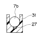
図5及び図6は本発明の第2実施形態にかかり、図5はカートに設けたスコープハンガーと内視鏡とを説明する図、図6は図5のA−A線断面図であり、スコープハンガーに設けた温度センサと内視鏡との関係を説明する図である。
【0058】
図5及び図6に示すように本実施形態においては、前記カート6に設けられている非検査時に内視鏡2を保持するためのスコープハンガー30に温度検知手段として熱電対等で形成した接触型温度センサ27を設けるとともに、告知手段である表示部26を設けている。
【0059】
前記スコープハンガー30には内視鏡2の操作部11及び操作部折れ止め部材7bを保持する保持部31が設けられており、この保持部31の所定位置に前記接触型温度センサ27が前記操作部折れ止め部材7bの表面に接触するように配置されている。その他の構成は前記第1実施形態と同様であり、同部材には同符合を付して説明を省略する。
【0060】
高圧蒸気滅菌後の内視鏡2を、スコープハンガー30に保持する。すると、前記内視鏡2の操作部折れ止め部材7bに前記接触型温度センサ27が接触する。すると、図示しない制御部からの指示に基づいて前記操作部折れ止め部材7bの表面温度の測定を行わせる一方、この測定した温度データの中から所定の温度データを前記表示部26に表示させる。
【0061】
このように、本実施形態においては、検査前に必ず内視鏡が保持されるスコープハンガーに接触型温度センサ及び表示部を設けたことによって、検査開始時まで温度測定のために内視鏡に触れることが防止されるので、滅菌状態を確実に保持することができる。その他の作用及び効果は前記第1実施形態と同様である。
【0062】
図7は本発明の第3実施形態にかかるリークテスターを説明する図である。
図に示すように本実施形態においては、前記内視鏡2を水没下に配置し、この内視鏡2の内部を加圧して穴あき等の破損を検知するリークテスター35に温度検知手段である赤外線温度センサ24を設けるとともに、告知手段である表示部26を設けている。
【0063】
前記赤外線温度センサ24は、前記内視鏡2の挿入部10の先端側部が挿入配置される温度検査穴35aの内面開口近傍に設けられている。このことによって、前記第1実施形態と同様に、温度検査穴35a内に挿入されてくる先端硬性部13から湾曲部14までの外表面の温度の測定を行える。
【0064】
なお、前記リークテスター35には加圧ポンプ36と、内視鏡2にこの加圧ポンプ36からの加圧空気を導入する接続管路37とが設けられている。その他の構成は上述した実施形態と同様であり、同部材には同符合を付して説明を省略する。
【0065】
このように、比較的安価な装置であるリークテスターに温度検知手段及び告知手段を設けることによって、たとえ検査によってホワイトバランスキャップやスコープハンガーを有するカートが使用されている場合でも、リークテストを行うことによって、内視鏡の温度検知を行うことができる。その他の作用及び効果は上述した実施形態と同様である。
【0066】
図8は本発明の第4実施形態にかかる内視鏡システムの他の構成例を説明する図である。
図に示すように本実施形態においては、前記内視鏡2のコネクタ12a内部に温度検知手段として温度センサ28を設けている。そして、告知手段を前記モニタ5としている。
【0067】
このため、本実施形態では前記ビデオプロセッサ4に比較部25a,予想時間算出部25bを備えた制御部25Aを設けている。なお、符号29は、前記内視鏡2のCCDを制御し、このCCDで得られた電気信号を画像信号に処理する画像制御部である。
【0068】
前記温度センサ28と電気コネクタ部12bとは信号ライン28aによって接続され、この電気コネクタ部12bに信号ケーブル4aを接続することによってビデオプロセッサ4に設けられた前記制御部25Aに接続されている。なお、制御部25Aは、画像制御部29と電気的に接続されている。
【0069】
高圧蒸気滅菌終了後、内視鏡検査の準備を行うため、内視鏡2を信号ケーブル4aを介してビデオプロセッサ4に接続する。すると、温度センサ28と制御部25Aとが電気的に接続され、このことによって、制御部25Aの比較部25aによって温度センサ28で測定された温度データの基準値Tとの比較が行われる。
【0070】
ここで、比較結果がt>Tの場合には画像制御部29を介してモニタ5の画面上に内視鏡2の温度が使用に適さない旨のメッセージや図、記号を表示させるとともに、図示しないスピーカーにより警告音を発生させ、前記予想時間算出部25bによって算出された予想時間を表示させる。そして、この制御部25Aでは、一定時間毎、例えば3分ごとに温度センサ28で測定された温度データを比較部25aにて比較し、判定を行うとともに予想時間算出部25bで使用可能な温度になる予想時間を算出して、モニタ5の表示を更新し、警告音を発生させる。
【0071】
そして、比較結果がt<Tに変化したとき、前記警告音と明確に区別できる音や音声を発生させるとともに、モニタ5の画面表示を変化させて内視鏡2の温度が使用可能な状態になったことを告知する。
【0072】
このように、温度センサを内視鏡に設け、この温度センサを制御する制御部を外部装置であるビデオプロセッサに設け、告知手段を内視鏡検査に必要な外部装置であるモニタとしたことによって、検査前に確実に温度の検知を行うことができる。
【0073】
なお、この実施形態において比較結果がt>Tの場合、上述した告知を行うとともに、前記制御部25Aから、画像制御部29から内視鏡2の撮像手段へ電源供給を強制的に停止させたり、モニタ5の画面上への観察画像の表示を停止させたり、光源装置3から内視鏡2への照明光の供給を停止させる等の制御を行うようにしてもよい。
【0074】
また、湾曲部の湾曲操作を電気的に行うタイプの内視鏡では湾曲操作にかかわる電気の供給を停止させるようにしてもよい。これらの制御を行うことにより、内視鏡2を強制的に検査に使用できない状態にして、内視鏡が誤使用されることを確実に防止することができる。
【0075】
なお、これらの制御を行った場合でも、モニタ5の画面上には内視鏡2の温度が使用に適さない旨のメッセージ等が告知されたままの状態にしているので、作業者が内視鏡2の故障と間違えることがない。
【0076】
また、本実施形態においては制御部25Aをビデオプロセッサ4に設けているが、この制御部25Aを設ける装置はビデオプロセッサ4に限らず、光源装置3等であってもよい。つまり、検査時に内視鏡2に接続されて使用される外部装置であればいかなるものであってもよい。
【0077】
さらに、内視鏡2に温度センサ28とともに、制御部25やモニタの画面やスピーカーにかわる告知手段を設けるようにしても良く、この場合には特別な外部装置を不要にして、既存の外部装置の使用を可能にして互換性が良くなる。
【0078】
又、温度センサ28の配置位置はコネクタ12aの内部に限定されるものではなく、挿入部10の先端部の図示しないCCD近傍に設けるようにしてもよく、内視鏡2に設けられていればよい。
【0079】
ところで、前記特開平5−337171号公報のオートクレーブ装置では、内視鏡が冷却されるまで内視鏡をオートクレーブ装置から取り出すことができないため、高圧蒸気滅菌のサイクルタイムが長くなってしまう。したがって、症例間の滅菌には適さず、又、多数の内視鏡がある場合には全てを滅菌処置するのに非常に時間がかかるという問題があった。
【0080】
また、特開平6−105796号公報にはオートクレーブ滅菌後、換気装置によって乾燥用管路の換気を行い、スコープ内部を除湿して乾燥、冷却を行うことが示されているが、内視鏡の内部のみを乾燥、冷却する構成であるため、内視鏡の外表面が冷却されず、冷却に時間がかかるという不具合があった。
【0081】
このため、高圧蒸気滅菌のサイクルタイムの短縮及び高圧蒸気滅菌後の内視鏡の冷却時間の短縮が可能な内視鏡システムが望まれていた。
【0082】
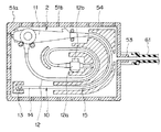
図9及び図10は高圧蒸気滅菌工程後に高温となっている内視鏡を冷却する冷却装置に係り、図9はトレイと送気ポンプとの関係を説明する図、図10は収納ケースに内視鏡を収納した状態を示す図である。
図9及び図10に示すように本実施形態においては滅菌用収納ケース50に送気ポンプ60を組み合わせる構成になっている。
【0083】
本実施形態の滅菌用収納ケース50のトレイ51aには送気チューブ61を介して送気ポンプ60が接続されるようになっている。前記送気チューブ61は、トレイ51aの側部に設けられて内外を連通する気体導入口53に着脱自在に接続される。
【0084】
前記トレイ51aには内外を連通して高圧蒸気滅菌時に内部に蒸気を導入する複数の通気孔51bが設けられている。また、トレイ51a内には収納配置される内視鏡2の各部の位置を規定して挿入部10の曲げ形状を所定形状に規制する規制部54が設けてある。
【0085】
ここで、内視鏡2の冷却作業について説明する。
内視鏡2の高圧蒸気滅菌が終了したなら、前記内視鏡2の電気コネクタ部12bから防水キャップ9aを取り外す。このことによって、電気コネクタ部12bに設けられている図示しない通気口が開放状態になる。
【0086】
次に、送気ポンプ60の送気チューブ61を気体導入口53に接続する。そして、前記送気ポンプ60によって外気をトレイ51a内部に強制的に送り込む。このトレイ51a内に送り込まれた外気は、前記通気孔51bよりトレイ51aの外部に排出されていく。このことにより、トレイ51a内が随時換気される。
【0087】
また、前記送気ポンプ60によって送り込まれた外気は、前記通気口より内視鏡2の内部にも導入されて、内視鏡内の空気も換気させる。
つまり、内視鏡2の外表面及び内部は、送気ポンプ60によって送り込まれる外気によって冷却される。
【0088】
このように、内視鏡が収納されるトレイ内に送気ポンプからの外気を送り込むことによって、高圧蒸気滅菌後の内視鏡の外表面及び内部に外気が行き渡たらせて冷却時間を大幅に短縮させることができる。
【0089】
また、挿入部の曲げ形状が規制部によって所定の形状に規制されているので、高温状態で軟化している外皮が急速に冷却されることによって、急激な曲がり癖がつくことを防止することができる。
【0090】
なお、気体導入口を設けたトレイを冷却専用の収容器としてもよい。また、この収容器に内視鏡を複数収納できるようにしてもよい。そして、その場合には送気ポンプの代わりに収納器自体に、外気を容器内に導入したり、排気する送風ファン等を設けるようにしてもよい。
【0091】
図11は高圧蒸気滅菌工程後に高温となっている内視鏡を冷却する冷却用収納容器の構成を説明する図である。
本実施形態においては図11に示すように、前記滅菌用収納ケース50と送気ポンプ60とを組み合わせる構成の代わりに、滅菌用収納ケース50を収納する冷却用収納容器70と換気冷却装置75とを組み合わせる構成にしている。
【0092】
前記冷却用収納容器70には気体導入口71と気体排出口72とが設けてある。この気体導入口71には換気冷却装置75に設けられている冷却器76に接続されて冷却風を送気する送気ポンプ77に接続された送気チューブ77aが着脱自在に接続されている。
【0093】
一方、前記気体排出口72には吸引ポンプ78に接続された吸引チューブ78aが接続されている。そして、これら吸引ポンプ78、冷却器76、送気ポンプ77は、制御部79に接続されて、それぞれの動作が制御されるようになっている。
【0094】
なお、冷却用収納容器70内は前記気体導入口71と気体排出口72以外は外部に対して密閉される構造であり、前記吸引ポンプ78は締切り時の圧力で大気圧に対して−0.07MPa〜−0.15MPa程度の能力を有している。
【0095】
ここで、内視鏡2の冷却作業について説明する。
内視鏡2の高圧蒸気滅菌が終了したなら、内視鏡2が収納された滅菌用収納ケース50を冷却用収納容器70内に収納し、この冷却用収納容器70を密閉状態にする。
【0096】
次に、制御部79の制御により吸引ポンプ78の動作を開始させる。すると、冷却用収納容器70内及び滅菌用収納ケース50内の内部圧力が大気圧に対して−0.07MPa〜−0.15MPa程度に下がる。前記内部圧力が内視鏡2の内部圧力よりも下がることにより、防水キャップ9aの圧力調整弁が開状態になって、内視鏡内の高圧蒸気滅菌によって湿度の高くなっている空気が外部へ放出されていく。そして、内視鏡2の内部圧力が前記内部圧力と略等しくなると圧力調整弁が閉状態になる。
【0097】
次いで、制御部79では送気ポンプ77を作動させ、気体導入口71から冷却用収納容器70内に冷却空気を送り込む。すると、滅菌用収納ケース50及び内視鏡2が冷却される。この滅菌用収納ケース50及び内視鏡2の冷却に使用された冷却空気は、随時、吸引ポンプ78により気体排出口72より排出されていく。
【0098】
そして、前記制御部79では前述した吸引ポンプ78のみの動作による減圧工程及び送気ポンプ77及び吸引ポンプ78の作動による冷却空気循環工程を3回繰り返し行わせる。このことによって、内視鏡2の外表面が冷却されるとともに、内視鏡2内部の高温で湿気を含んだ空気が略排出されて内視鏡2の内部が冷却、乾燥される。
【0099】
このように、内視鏡を滅菌用収納ケースに収納したままの状態で冷却作業を行うことによって、内視鏡外表面の冷却及び内部の冷却、乾燥を容易に行うことができる。
【0100】
このことによって、内視鏡を滅菌用収納ケースから取り出す作業や防水キャップを取り外す作業が不要となるので内視鏡2の滅菌状態の確保を確実、かつ容易に行える。また、上述した高圧蒸気滅菌装置における乾燥工程を省略することができる。
【0101】
なお、前記吸引ポンプ78の代わりに内視鏡検査室に設備されている、送気ポンプや送気源及び吸引ポンプを利用し、これらポンプの作動/停止を手動によって切り替えるようにしてもよい。また、内視鏡2を滅菌用収納ケース50に収納することなく、直接冷却用収納容器70に収納するようにしてもよい。この場合、防水キャップ9aを電気コネクタ部12bから取り外して前記通気口を開口状態にして冷却を行ってもよい。
【0102】
図12及び図13は高圧蒸気滅菌工程後に高温となっている内視鏡を冷却する内視鏡冷却装置に係り、図12は内視鏡冷却装置の構成を説明する図、図13は挿入部規制部の構成を説明する図である。
本実施形態においては図12に示すように複数の内視鏡2を配置することが可能な挿入部収容部材81と、冷却水送液装置82とで内視鏡冷却装置80を構成している。
【0103】
前記挿入部収容部材81の内部には内視鏡2の挿入部10を直線上に収容保持する略パイプ形状の挿入部規制部83が複数配置されている。前記挿入部規制部83の内径は30mm程度に形成されており、この挿入部規制部83の側面部には図13に示すように内孔と外部とを連通する複数の貫通孔83aが形成されている。また、前記挿入部収容部材81には冷却水導入口(以下導入口と略記する)81aと冷却水排出口(以下排出口と略記する)81bとが設けられている。
【0104】
前記冷却水送液装置82には送液ポンプ84と冷却器85とが設けられており、前記導入口81aには前記送液ポンプ84から延出する送液チューブ86が接続され、前記排出口81bには送液ポンプ84に接続されて排出液が冷却器85を通過するようにした排出チューブ87が接続されている。
【0105】
前記挿入部収容部材81には内視鏡2の挿入部10の長手方向に伸縮自在に構成されて、前記内視鏡2の操作部11を保持する高さ寸法を任意の高さに設定することが可能な内視鏡保持部88が設けられている。
【0106】
また、前記挿入部収容部材81の内部には熱伝導性の良い冷却媒体として例えば滅菌水等からなる冷却液90が満たされている。この挿入部収容部材81の深さ寸法は例えば0.6m〜1.5m程度に設定されており、挿入部10の大部分が冷却液90中に浸漬した状態になる。
【0107】
ここで、内視鏡2の冷却作業について説明する。
内視鏡2の高圧蒸気滅菌が終了したなら、内視鏡2の挿入部10を挿入部収容部材81の挿入部規制部83に挿入し、内視鏡2の操作部11を内視鏡保持部88に設置し、前記挿入部10ができるだけ冷却液90中に浸漬される状態になるよう、前記内視鏡保持部88の高さ調整を行う。このことによって冷却液90が前記挿入部規制部83の貫通孔83a等からこの挿入部規制部83内に流入して挿入部10を冷却する状態になる。
【0108】
次に、冷却液90を循環させるために送液ポンプ84を作動させる。すると、導入口81aから挿入部収容部材81内に冷却液90が流入されるとともに、排出口81bから冷却液90が随時排出されていく。この排出口81bから排出された冷却液90は冷却器85で冷却された後、再び送液ポンプ84によって挿入部収容部材81内を循環する。
【0109】
このように、冷却媒体として熱伝導性の良い液体を用いるとともに、この冷却媒体を冷却器を通して循環させることによって挿入部の冷却を効率良く行って冷却時間の短縮を図ることができる。
【0110】
また、内視鏡の挿入部は、挿入部規制部によって直線化された状態で循環する冷却液によって冷却されるので、高圧蒸気滅菌工程で高温となり軟化している場合でも、冷却によって曲がり癖がつくことを防止することができる。
【0111】
さらに、内視鏡検査使用時に体腔内に挿入される挿入部のみを直接冷却する構成であるので、装置のコンパクト化を図ることができる。
【0112】
なお、前述したリークテスター35に冷却装置を設け、内視鏡2の内部加圧時に冷却空気を送り込み内部からの冷却を促進させる構成にしてもよい。
【0113】
図14及び図15は高圧蒸気滅菌工程後に高温となっている内視鏡を冷却する冷却容器に係り、図14は冷却容器の構成を説明する図、図15は図14のC−C断面図である。
本実施形態においては図14に示すように冷却容器91に内視鏡2の挿入部10を収納する挿入部収納部92を設けている。この挿入部収納部92の断面形状は、図15に示すように前記挿入部10の外形形状と略同一の内径と幅とを有するU字溝部93等の凹部によって形成されており、この挿入部収納部92に前記挿入部10を収納した際、この挿入部10の表面にU字溝部表面93が密着する密着面部になっている。また、前記冷却容器91の外表面には外気に対して、この冷却容器91の放熱性を高めるための複数の放熱フィン94が設けてある。
【0114】
なお、挿入部収納部92は前記挿入部10の略全長を収納できるようになっており、例えば0.6m〜2mの長さに設定される。また、前記冷却容器91は、前記挿入部10の可撓管部15や湾曲部14の表面を形成する樹脂材料よりも熱伝導率の高い樹脂材料や熱伝導率が非常に高い例えばアルミ合金等の金属により形成されている。
【0115】
ここで、内視鏡2の冷却作業について説明する。
内視鏡2の高圧蒸気滅菌が終了したなら、内視鏡2を冷却容器91に収納し、挿入部10を挿入部収納部92に配置させる。すると、前記挿入部10の熱は、この挿入部10に接触しているU字溝部93から冷却容器91に伝導し、放熱フィン94によって外気に放熱され、挿入部10が冷却される。なお、前記放熱フィン94を冷却水等にさらすことによって、内視鏡2を濡らすことなく、更に冷却速度を早められる。
【0116】
このように、内視鏡の表面を形成する樹脂材料等よりも熱伝導率の高い部材で形成された冷却容器に内視鏡を配置させることによって、内視鏡を効率よく速やかに冷却することができる。
【0117】
なお、前記冷却容器91を高圧蒸気滅菌可能な材質で前記トレイ51を兼ねるように形成してもよい。また、冷却容器91に前記スコープハンガー30と同様に内視鏡2の温度検知手段と告知手段とを設けるようにしてもよい。このことにより、前記スコープハンガー30と同様の効果を得られる。
【0118】
また、前記挿入部収納部92を設けた冷却容器91の代わりに、図16(a)に示すように前記挿入部収納部92の代わりとなる、例えば発泡ポリエチレン等からなる多数の気泡を有する軟質のスポンジ部材95を設置した冷却容器91Aとしてもよい。このスポンジ部材95には例えば滅菌水等の冷却液を含浸させておく。なお、冷却容器91Aのその他の形状、材質は前記冷却容器91と同様である。
【0119】
前記スポンジ部材95の表面の硬度は、内視鏡2を載置した際、この内視鏡2の自重によって変形する硬さである。つまり、前記内視鏡2をスポンジ部材95上に置くと、図16(b)に示すように内視鏡2の挿入部10や操作部11等の側面がスポンジ部材95に埋没した状態になる。
【0120】
ここで、内視鏡2の冷却作業について説明する。
内視鏡2の高圧蒸気滅菌が終了したなら、冷却容器91Aのスポンジ部材95上に内視鏡2を配置させる。すると、内視鏡2の自重によってスポンジ部材95が弾性変形して、このスポンジ部材95が挿入部10や操作部11に密着する。このことによって、スポンジ部材95及びこのスポンジ部材95に含まれている冷却水によって、冷却される。
【0121】
このように、冷却容器に冷却液を含浸させたスポンジ部材を配置させたことによって、内視鏡の表面と熱伝導性の良い部材と接触度合い(接触面積)が増大して冷却効果を大幅に増大させることができる。
【0122】
なお、このスポンジ部材95を設ける代わりに、内視鏡2の自重によりこの内視鏡2が埋没する程度の硬度を有するゲル状の冷却媒体を用いても同様の作用及び効果を得られる。この場合には冷却のために液体を使用しないので、液体の拭き取り等の手間を省ける。
【0123】
図17は冷却機能を備えたスコープハンガーの構成を説明する図である。
図に示すように本実施形態に置いてはスコープハンガー100には内視鏡2の操作部11を保持する保持部101が設けられている。この保持部101は、前記操作部11の外表面との接触面積が大きくなるよう、この操作部11の外形形状と略同様の曲面で形成されている。
【0124】
また、前記保持部101を、前記操作部11の弾性変形可能な部材で形成されている操作部折れ止め部材7bをも保持するようにしてもよい。このことによって、保持部101の接触面積がさらに大きくなる。
【0125】
また、前記保持部101を弾性変形可能な部材で形成し、この保持部101に操作部11を載置させた際、この内視鏡2の自重によって保持部101が変形して操作部11の外表面に密着する構成にしてもよい。
【0126】
前記保持部101は、前記操作部11や操作部折れ止め部材7b等の外表面を形成する樹脂等からなる材質よりも、熱伝導率が高い樹脂材料や、非常に熱伝導率の高い例えばアルミニウム等の金属材料で、かつ高圧蒸気滅菌可能な材料により形成されている。
【0127】
また、この保持部101は、それ自体の容積を大きくしたり、保持部101が固定される支持部材102の熱伝導率を、前記保持部101と同じ又はさらに良好な材料で構成し、保持部101と支持部材102との接触面を設けて保持部101と支持部材102との合計での容積を大きくさせることにより、吸収できる熱容量が大きく構成される。
【0128】
前記保持部101と支持部材102とは着脱自在に構成されており、保持部101は支持部材102から取り外して内視鏡2とともに高圧蒸気滅菌可能に構成されている。保持部101や支持部材102に前述した放熱フィン94を設ける構成にしてもよい。
【0129】
ここで、内視鏡2の冷却作業について説明する。
内視鏡2及び保持部101の高圧蒸気滅菌が終了したなら、保持部101を支持部材102に接続し、内視鏡2の挿入部10を伸ばした状態になるように設置する。このことにより、検査準備の間、内視鏡2はスコープハンガー100に保持される。
【0130】
内視鏡2の熱は、操作部11や操作部折れ止め部材7bを介して熱伝導性の良い保持部101に伝導され、更に支持部材102に伝導されて外気に放射されて内視鏡2が冷却される。
【0131】
このように、スコープハンガーの保持部や、支持部材を、内視鏡の外表面を形成する材質よりも、熱伝導率が高い部材で構成したことによって、内視鏡をスコープハンガーにかけた状態で効率よく内視鏡の冷却を行うことができる。
【0132】
また、挿入部が直線化された状態で冷却されるので冷却によって曲がり癖がつくことを防止することができる。
【0133】
さらに、保持部が高圧蒸気滅菌可能なので、検査直前まで滅菌状態を保つことができる。
【0134】
なお、前記保持部101に温度検知手段及び告知手段を設けるようにしてもよい。
【0135】
尚、本発明は、以上述べた実施形態のみに限定されるものではなく、発明の要旨を逸脱しない範囲で種々変形実施可能である。
【0136】
[付記]
以上詳述したような本発明の上記実施形態によれば、以下の如き構成を得ることができる。
【0137】
(1)内視鏡と、
この内視鏡の温度を測定する温度検知手段と、
この温度検知手段で得られた測定値を基に、前記内視鏡の温度が内視鏡が使用可能な状態であるか否かを判断するための情報を告知する告知手段と、
を具備することを特徴とする内視鏡システム。
【0138】
(2)前記温度検知手段及び前記告知手段を一体にした内視鏡温度測定装置を具備する付記1記載の内視鏡システム。
【0139】
(3)前記温度検知手段及び前記告知手段を、前記内視鏡に組み合わせて使用され、内視鏡検査前に使用される機器の何れかに設けた付記1記載の内視鏡システム。
【0140】
(4)前記温度検知手段は、前記内視鏡の挿入部の少なくとも一部の外表面の温度を測定する付記1記載の内視鏡システム。
【0141】
(5)前記温度検知手段は、所定部位の温度を測定する付記1記載の内視鏡システム。
【0142】
(6)前記温度検知手段は、前記内視鏡の挿入部先端側に設けられた湾曲部より先端側の温度を測定する付記5記載の内視鏡システム。
【0143】
(7)前記機器は、内視鏡画像のホワイトバランスを設定するためのホワイトバランス設定基準観察対象部材である付記3記載の内視鏡システム。
【0144】
(8)前記機器は、前記内視鏡を保持する内視鏡保持装置である付記3記載の内視鏡システム。
【0145】
(9)前記温度検知手段は、非接触型の温度センサである付記1記載の内視鏡システム。
【0146】
(10)温度検知手段を有する内視鏡と、
この内視鏡若しくは内視鏡に接続される外部装置の少なくとも何れかに前記内視鏡の温度が使用可能な状態であるか否かを判断するための情報を告知する告知手段と、
を具備する付記1記載の内視鏡システム。
【0147】
(11)前記温度検知手段で測定された温度データを予め設定した設定値と比較する比較手段を有し、
前記告知手段は、前記比較手段の比較結果に基づき、前記内視鏡の温度が使用可能な状態であるか否かを告知する付記2又は付記10記載の内視鏡システム。
【0148】
(12)前記比較手段の比較結果が使用可能な状態でない場合、前記内視鏡及び外部装置を使用不能にする強制停止手段を具備する付記11記載の内視鏡システム。
【0149】
(13)前記温度検知手段で測定された温度データに基づいて、前記内視鏡の温度が使用可能な状態に下がるまでに要する時間を算出する時間算出手段を有し、前記告知手段は、前記時間算出手段で算出した時間を告知する付記2又は付記10記載の内視鏡システム。
【0150】
(14)内視鏡を冷却する内視鏡の冷却装置において、
少なくとも挿入部の一部を収納可能なケース本体と、
冷却媒体と、
この冷却媒体を前記ケース本体収容部に導入する導入手段と、
を具備する内視鏡冷却装置
(15)前記挿入部の所定位置を直線形状又は所定の曲げ形状に保持する規制部を有する付記14記載の内視鏡冷却装置。
【0151】
(16)内視鏡の温度を測定する温度検知手段と、
この温度検知手段で得た温度データを基に、前記内視鏡の温度が使用可能な状態であるか否かを判断するための情報を告知する告知手段と、
を有する付記14記載の内視鏡冷却装置。
【0152】
(17)前記内視鏡の高圧蒸気滅菌を行う際、前記内視鏡を収容する内外が非気密に形成された高圧蒸気滅菌用収納容器を、収容可能に形成したケース本体を備える付記14記載の内視鏡冷却装置。
【0153】
(18)細長で軟性の挿入部を有する内視鏡を収容して冷却する冷却容器において、
前記内視鏡の挿入部の外表面の少なくとも一部に密着する密着面部を具備する冷却容器。
【0154】
(19)前記密着面部に前記挿入部を強制的に冷却する冷却部を具備する付記18記載の冷却容器。
【0155】
(20)前記密着面部は、液体が浸透して含有可能で、内視鏡の自重によって表面形状が変形可能な多孔質材料で形成される付記19記載の冷却容器。
【0156】
(21)前記冷却媒体は、前記内視鏡の自重により表面形状が変形可能なゲル状材料である付記19記載の冷却容器。
【0157】
(22)前記密着面部を、この密着面部に密着する前記挿入部外表面の熱伝導率よりも高い材料で形成した付記18記載の冷却容器。
【0158】
(23)蒸気滅菌に耐性を有する材料にて形成した付記18記載の冷却容器。
【0159】
(24)前記挿入部の所定の位置を直線形状又は所定の曲げ形状に保つ保持手段を有する付記18記載の冷却容器。
【0160】
(25)細長で軟性の挿入部を有する内視鏡を、前記挿入部を直線化した状態で保持する内視鏡保持装置において、
前記内視鏡の少なくとも一部を保持する保持部を支持部材に対して着脱自在に設け、
この保持部に前記内視鏡外表面の少なくとも一部に接触する接触部を設け、この接触部を熱伝導率が前記内視鏡外表面よりも高く、高圧蒸気滅菌に耐性を有する部材にて形成した内視鏡保持装置。
【0161】
(26)前記保持部の熱容量を、内視鏡の熱容量よりも大きく形成した付記25記載の内視鏡保持装置。
【0162】
(27)前記保持部を支持部材に接触させて接続し、この支持部材を前記保持部よりも熱容量を大とし、前記接続部における支持部材の外表面を熱伝導性の高い部材にて形成した付記25記載の内視鏡保持装置。
【0163】
(28)前記保持部を前記内視鏡の操作部の把持部外形状に沿った形状に形成した付記25記載の内視鏡保持装置。
【0164】
【発明の効果】
以上説明したように本発明によれば、特別なオートクレーブ装置が不要で、高圧蒸気滅菌後に内視鏡の温度が使用可能な状態であるか否かの確認を確実かつ容易に行える互換性に優れた内視鏡システムを提供することができる。
【図面の簡単な説明】
【図1】図1ないし図3は本発明の第1実施形態に係り、図1は内視鏡装置の概略構成を説明する図
【図2】ホワイトバランス調整に用いる温度測定装置付きホワイトバランスキャップを示す図
【図3】ホワイトバランスキャップの構成を説明する図
【図4】温度測定装置付きホワイトバランスキャップの他の構成を説明する図
【図5】図5及び図6は本発明の第2実施形態にかかり、図5はカートに設けたスコープハンガーと内視鏡とを説明する図
【図6】図5のA−A線断面図であり、スコープハンガーに設けた温度センサと内視鏡との関係を説明する図
【図7】本発明の第3実施形態にかかるリークテスターを説明する図
【図8】本発明の第4実施形態にかかる内視鏡システムの他の構成例を説明する図
【図9】図9及び図10は高圧蒸気滅菌工程後に高温となっている内視鏡を冷却する冷却装置に係り、図9はトレイと送気ポンプとの関係を説明する図、
【図10】収納ケースに内視鏡を収納した状態を示す図
【図11】高圧蒸気滅菌工程後に高温となっている内視鏡を冷却する冷却用収納容器の構成を説明する図
【図12】図12及び図13は高圧蒸気滅菌工程後に高温となっている内視鏡を冷却する内視鏡冷却装置に係り、図12は内視鏡冷却装置の構成を説明する図
【図13】挿入部規制部の構成を説明する図
【図14】図14及び図15は高圧蒸気滅菌工程後に高温となっている内視鏡を冷却する冷却容器に係り、図14は冷却容器の構成を説明する図
【図15】図14のC−C断面図
【図16】冷却容器の他の構成を説明する図
【図17】冷却機能を備えたスコープハンガーの構成を説明する図
【符号の説明】
10…挿入部
21…ホワイトバランスキャップ
22…筒状部
23…被写体部
24…赤外線温度センサ
25…制御部
26…表示部[0001]
BACKGROUND OF THE INVENTION
The present invention relates to an endoscope system having an endoscope that performs sterilization after use by high-pressure steam sterilization.
[0002]
[Prior art]
Conventionally, by inserting a long and thin insertion portion into a body cavity, the inside of a body cavity can be observed, and various medical treatments can be performed using a treatment instrument inserted into a treatment instrument channel as necessary. Endoscopes are widely used.
[0003]
In particular, endoscopes used in the medical field are used to observe various organs by inserting an insertion portion into a body cavity and using a treatment instrument inserted into a treatment instrument channel of an endoscope. Take action.
[0004]
For this reason, when an endoscope or treatment tool that has been used once is reused for another patient, it is necessary to prevent infection between patients via the endoscope or treatment tool. Had to clean and disinfect.
[0005]
In recent years, autoclave sterilization (high pressure steam sterilization), which can be used immediately after sterilization without complicated work and has a low running cost, is becoming the mainstream of disinfection sterilization treatment of medical devices.
[0006]
For example, Japanese Patent Laid-Open No. 5-337171 has temperature detection means for detecting the temperature of an autoclave apparatus main body in which a medical device is stored and the temperature of the medical device, and the output of the temperature detection means is the use of the medical device. There is shown an autoclave device provided with a door lock / unlock mechanism that prohibits the door from being opened when the temperature does not fall below a reference temperature at which the temperature can be reduced.
[0007]
[Problems to be solved by the invention]
However, in the autoclave device disclosed in JP-A-5-337171, the autoclave device is filled with high-temperature and high-pressure steam at 130 ° C. or higher during the sterilization process. There was a problem.
[0008]
Further, no consideration has been given to the case where the endoscope is autoclaved with an existing autoclave device.
[0009]
The present invention has been made in view of the above circumstances, does not require a special autoclave device, and can be used to reliably and easily confirm whether or not the temperature of the endoscope is usable after high-pressure steam sterilization. It aims at providing the endoscope system excellent in property.
[0010]
[Means for Solving the Problems]
The endoscope system of the present invention is With insert An endoscope, Provided toward the insertion portion arranged at a predetermined position, The distal end side of the bending portion provided on the distal end side of the insertion portion Outer surface A temperature detection unit for measuring temperature and information for determining whether or not the temperature of the insertion portion in the endoscope is usable based on the measurement value measured by the temperature detection unit are notified. And a notification means.
[0011]
According to this configuration, the operator can easily determine whether or not the temperature of the endoscope is in a usable temperature state based on the information notified to the notification means.
[0012]
DETAILED DESCRIPTION OF THE INVENTION
Embodiments of the present invention will be described below with reference to the drawings.
1 to 3 relate to a first embodiment of the present invention, FIG. 1 is a diagram illustrating a schematic configuration of an endoscope apparatus, FIG. 2 is a diagram illustrating a white balance cap with a temperature measuring device used for white balance adjustment, FIG. 3 is a diagram illustrating the configuration of the white balance cap.
[0013]
As shown in FIG. 1, an
[0014]
The
[0015]
A
[0016]
The connecting portion between the
[0017]
The elongated and
[0018]
In addition to the
[0019]
An
[0020]
The
[0021]
Further, when a high frequency leakage current is generated in the
[0022]
The
[0023]
When the
[0024]
The CCD, which is an imaging means provided in the
[0025]
As shown in FIGS. 2 and 3, the
The
[0026]
Further, one or more
[0027]
The
[0028]
That is, the
[0029]
Here, typical conditions for autoclaving the
Typical conditions are American Standards Association approved and American Standard ANSI / AAMI ST37-1992 issued by the Medical Device Development Association. Prevacuum type sterilization process at 132 ° C for 4 minutes, Gravity type sterilization process at 132 ° C. 10 minutes.
[0030]
The temperature condition during the sterilization process of high-pressure steam sterilization varies depending on the type of the high-pressure steam sterilization apparatus and the time of the sterilization process, but is generally set in the range of about 115 ° C to 138 ° C. Some sterilizers can be set to around 142 ° C.
[0031]
About time conditions, it changes with temperature conditions of a sterilization process. Generally, it is set to about 3 to 60 minutes. Some types of sterilizers can be set to about 100 minutes.
[0032]
The pressure in the sterilizer in this step is generally set to about +0.2 MPa with respect to atmospheric pressure.
[0033]
Next, the high-pressure steam sterilization process of an endoscope in a general pre-vacuum type will be briefly described.
First, a
[0034]
This pre-vacuum process is a process for infiltrating the steam into the details of the sterilization target device during the sterilization process. By reducing the pressure inside the sterilization apparatus, high-pressure and high-temperature steam is distributed throughout the sterilization target device. Become. The pressure in the sterilizer in this pre-vacuum process is generally set to about -0.07 to -0.09 MPa with respect to atmospheric pressure.
[0035]
However, when the pressure in the sterilizer decreases in the pre-vacuum process, the external pressure becomes lower than the internal pressure of the
[0036]
Next, sterilization is performed by sending high-pressure high-temperature steam into the sterilizer (sterilization process).
In this sterilization step, the inside of the sterilizer is pressurized. Then, a pressure difference is generated such that the external pressure is higher than the internal pressure of the
[0037]
However, the high-pressure steam is formed of fluoro rubber, silicon rubber, or the like which is a sealing means provided in the outer tube 15c of the
[0038]
At this time, the exterior body of the
[0039]
Next, in order to dry the sterilization target device after sterilization, the inside of the sterilization apparatus is again depressurized and dried (drying step) after the sterilization step. In this drying step, the inside of the sterilizer is decompressed to remove steam from the inside of the sterilizer, thereby promoting the drying of the sterilization target device in the sterilizer. The pressure in the sterilizer in this drying step is generally set to about -0.07 MPa to -0.09 MPa with respect to atmospheric pressure. In addition, the said drying process is arbitrarily performed as needed.
[0040]
In the decompression process after the sterilization process, a pressure difference is generated such that the pressure in the sterilization apparatus decreases and the external pressure becomes lower than the internal pressure of the
[0041]
At the end of the entire high-pressure steam sterilization process, the exterior body of the
[0042]
As described above, since the inside and outside of the
[0043]
In using the
[0044]
In this insertion state and white balance adjustment state, the
[0045]
At this time, when the temperature displayed on the
[0046]
When the display temperature is 40 ° C., this 40 ° C. is substantially the same as the body temperature, and thus the temperature at which the subject hardly feels uncomfortable during the endoscopic examination. That is, this temperature is set as a reference temperature for determining whether or not to perform endoscopy.
[0047]
Thus, by providing temperature detection means such as an infrared temperature sensor on a white balance cap for white balance adjustment that is always used before endoscopy, and displaying the result measured by the infrared temperature sensor on the display unit In addition, the temperature of the insertion portion of the endoscope can be surely confirmed by substantially the same work as the normal white balance adjustment work. This makes it easy to check whether the temperature of the endoscope after autoclaving is in a usable state.
[0048]
In addition, since the distal end surface of the insertion portion of the endoscope is brought into contact with the subject portion for white balance adjustment, temperature measurement up to a predetermined position can be reliably performed.
[0049]
As a result, when adjusting the white balance, the operator usually holds the flexible tube, so that the temperature of the flexible tube can be recognized directly by hand, while the operator touches it until the normal inspection starts. The operator can grasp the temperature of the entire insertion portion by checking the temperature on the tip side from the bending portion not present on the display portion.
[0050]
Furthermore, by using an infrared temperature sensor that can be measured in a non-contact manner with respect to an object to be measured as a temperature detection means, it is possible to perform accurate temperature measurement without variations in measurement temperature caused by contact state or the like.
[0051]
In the present embodiment, the
[0052]
In addition, as shown in the figure explaining the other structure of the white balance cap with a temperature measuring device in FIG. 4, the
[0053]
Thus, when the comparison result in the
[0054]
When the expected time has elapsed, the temperature is confirmed again using the
Note that the
[0055]
Thus, based on the comparison result between the temperature data obtained by the infrared temperature sensor and the reference value, the user can easily and appropriately determine whether the endoscope is at a usable temperature or not. Can make decisions.
[0056]
In addition, the expected time until the endoscope is cooled is calculated by the expected time calculation unit, and the expected time is displayed on the display unit. Until the approximate time, other work such as inspection preparation work can be performed.
[0057]
5 and 6 are related to a second embodiment of the present invention, FIG. 5 is a view for explaining a scope hanger and an endoscope provided in a cart, and FIG. 6 is a cross-sectional view taken along line AA in FIG. It is a figure explaining the relationship between the temperature sensor provided in the scope hanger and the endoscope.
[0058]
As shown in FIGS. 5 and 6, in this embodiment, the
[0059]
The
[0060]
The
[0061]
Thus, in this embodiment, by providing the contact-type temperature sensor and the display unit on the scope hanger that always holds the endoscope before the inspection, the endoscope is used for temperature measurement until the start of the inspection. Since touching is prevented, the sterilized state can be reliably maintained. Other operations and effects are the same as those in the first embodiment.
[0062]
FIG. 7 is a view for explaining a leak tester according to the third embodiment of the present invention.
As shown in the figure, in the present embodiment, the
[0063]
The
[0064]
The
[0065]
In this way, a leak tester, which is a relatively inexpensive device, is provided with temperature detection means and notification means, so that even if a cart having a white balance cap or scope hanger is used for inspection, a leak test can be performed. Thus, the temperature of the endoscope can be detected. Other operations and effects are the same as those of the above-described embodiment.
[0066]
FIG. 8 is a diagram for explaining another configuration example of the endoscope system according to the fourth embodiment of the present invention.
As shown in the figure, in the present embodiment, a
[0067]
Therefore, in this embodiment, the
[0068]
The
[0069]
After completion of the high-pressure steam sterilization, the
[0070]
Here, when the comparison result is t> T, a message, a figure, or a symbol indicating that the temperature of the
[0071]
When the comparison result changes to t <T, a sound or sound that can be clearly distinguished from the warning sound is generated, and the screen display of the
[0072]
Thus, the temperature sensor is provided in the endoscope, the control unit for controlling the temperature sensor is provided in the video processor that is an external device, and the notification means is a monitor that is an external device necessary for endoscopic examination. The temperature can be reliably detected before inspection.
[0073]
In this embodiment, when the comparison result is t> T, the above-described notification is performed, and the power supply is forcibly stopped from the
[0074]
In addition, in an endoscope of a type that electrically performs a bending operation of the bending portion, the supply of electricity related to the bending operation may be stopped. By performing these controls, it is possible to reliably prevent the
[0075]
Even when these controls are performed, a message indicating that the temperature of the
[0076]
In the present embodiment, the
[0077]
Further, the
[0078]
Further, the arrangement position of the
[0079]
By the way, in the autoclave device disclosed in Japanese Patent Laid-Open No. 5-337171, since the endoscope cannot be taken out of the autoclave device until the endoscope is cooled, the cycle time of high-pressure steam sterilization becomes long. Therefore, there is a problem that it is not suitable for sterilization between cases, and when there are a large number of endoscopes, it takes a very long time to sterilize all of them.
[0080]
Japanese Patent Application Laid-Open No. 6-105796 discloses that after the autoclave sterilization, the drying pipeline is ventilated by a ventilator, and the inside of the scope is dehumidified to be dried and cooled. Since only the inside is dried and cooled, the outer surface of the endoscope is not cooled, and there is a problem that it takes time for cooling.
[0081]
Therefore, an endoscope system that can shorten the cycle time of autoclaving and shorten the cooling time of the endoscope after autoclaving has been desired.
[0082]
FIGS. 9 and 10 relate to a cooling device that cools the endoscope that is at a high temperature after the high-pressure steam sterilization process, FIG. 9 is a diagram illustrating the relationship between the tray and the air supply pump, and FIG. It is a figure which shows the state which accommodated the endoscope.
As shown in FIGS. 9 and 10, in this embodiment, the
[0083]
An
[0084]
The
[0085]
Here, the cooling operation of the
When the high-pressure steam sterilization of the
[0086]
Next, the
[0087]
Further, the outside air sent by the
That is, the outer surface and the inside of the
[0088]
In this way, by sending the outside air from the air feed pump into the tray in which the endoscope is housed, the outside air spreads over the outer surface and inside of the endoscope after high-pressure steam sterilization, greatly reducing the cooling time. It can be shortened.
[0089]
In addition, since the bending shape of the insertion portion is regulated to a predetermined shape by the regulation portion, it is possible to prevent the outer skin softened in a high temperature state from being rapidly cooled, thereby preventing a sudden bending wrinkle. it can.
[0090]
In addition, it is good also considering the tray provided with the gas inlet as a container only for cooling. Further, a plurality of endoscopes may be stored in the container. In that case, a blower fan or the like for introducing outside air into the container or exhausting air may be provided in the container instead of the air supply pump.
[0091]
FIG. 11 is a diagram illustrating a configuration of a cooling storage container that cools the endoscope that is at a high temperature after the high-pressure steam sterilization step.
In the present embodiment, as shown in FIG. 11, instead of the configuration in which the
[0092]
The cooling
[0093]
On the other hand, a
[0094]
The inside of the cooling
[0095]
Here, the cooling operation of the
When the high-pressure steam sterilization of the
[0096]
Next, the operation of the
[0097]
Next, the
[0098]
Then, the
[0099]
In this way, by performing the cooling operation while the endoscope is stored in the sterilization storage case, it is possible to easily cool the outer surface of the endoscope, cool the inside, and dry the endoscope.
[0100]
This eliminates the need to take out the endoscope from the sterilization storage case or remove the waterproof cap, so that the sterilized state of the
[0101]
Instead of the
[0102]
12 and 13 relate to an endoscope cooling device that cools an endoscope that is at a high temperature after the high-pressure steam sterilization process, FIG. 12 is a diagram illustrating the configuration of the endoscope cooling device, and FIG. It is a figure explaining the structure of a control part.
In the present embodiment, as shown in FIG. 12, an
[0103]
Inside the insertion
[0104]
The cooling
[0105]
The insertion
[0106]
Further, the insertion
[0107]
Here, the cooling operation of the
When the high-pressure steam sterilization of the
[0108]
Next, the
[0109]
Thus, while using a liquid with good thermal conductivity as a cooling medium, and circulating the cooling medium through the cooler, the insertion portion can be efficiently cooled to reduce the cooling time.
[0110]
In addition, since the insertion portion of the endoscope is cooled by the coolant that circulates in a straight line by the insertion portion restricting portion, even if it becomes high temperature and softened in the high-pressure steam sterilization process, the bending wrinkles are caused by cooling. It can prevent sticking.
[0111]
Furthermore, since only the insertion part inserted into the body cavity is directly cooled when the endoscopy is used, the apparatus can be made compact.
[0112]
In addition, a cooling device may be provided in the above-described
[0113]
14 and 15 relate to a cooling container that cools the endoscope that is at a high temperature after the high-pressure steam sterilization process, FIG. 14 is a diagram illustrating the configuration of the cooling container, and FIG. 15 is a cross-sectional view taken along the line CC in FIG. It is.
In the present embodiment, as shown in FIG. 14, an insertion
[0114]
In addition, the insertion
[0115]
Here, the cooling operation of the
When the high-pressure steam sterilization of the
[0116]
In this way, the endoscope can be efficiently and quickly cooled by arranging the endoscope in a cooling container formed of a member having a higher thermal conductivity than the resin material or the like that forms the surface of the endoscope. Can do.
[0117]
The cooling
[0118]
Further, instead of the cooling
[0119]
The hardness of the surface of the
[0120]
Here, the cooling operation of the
When the high-pressure steam sterilization of the
[0121]
Thus, by arranging the sponge member impregnated with the cooling liquid in the cooling container, the degree of contact (contact area) between the endoscope surface and the member having good thermal conductivity is increased, and the cooling effect is greatly increased. Can be increased.
[0122]
It should be noted that the same action and effect can be obtained by using a gel-like cooling medium having such a hardness that the
[0123]
FIG. 17 is a diagram illustrating a configuration of a scope hanger having a cooling function.
As shown in the drawing, in the present embodiment, the
[0124]
Further, the holding
[0125]
Further, when the holding
[0126]
The holding
[0127]
In addition, the holding
[0128]
The holding
[0129]
Here, the cooling operation of the
When the high-pressure steam sterilization of the
[0130]
The heat of the
[0131]
In this way, the scope hanger holding part and the support member are made of a material having higher thermal conductivity than the material forming the outer surface of the endoscope, so that the endoscope is placed on the scope hanger. The endoscope can be efficiently cooled.
[0132]
Further, since the insertion portion is cooled in a straight line state, it is possible to prevent bending and wrinkling due to cooling.
[0133]
Furthermore, since the holding part is capable of high-pressure steam sterilization, the sterilized state can be maintained until immediately before the inspection.
[0134]
The holding
[0135]
The present invention is not limited to the above-described embodiments, and various modifications can be made without departing from the spirit of the invention.
[0136]
[Appendix]
According to the embodiment of the present invention as described above in detail, the following configuration can be obtained.
[0137]
(1) an endoscope;
Temperature detecting means for measuring the temperature of the endoscope;
Based on the measurement value obtained by this temperature detection means, a notification means for notifying information for determining whether or not the temperature of the endoscope is in a usable state,
An endoscope system comprising:
[0138]
(2) The endoscope system according to
[0139]
(3) The endoscope system according to
[0140]
(4) The endoscope system according to
[0141]
(5) The endoscope system according to
[0142]
(6) The endoscope system according to
[0143]
(7) The endoscope system according to
[0144]
(8) The endoscope system according to
[0145]
(9) The endoscope system according to
[0146]
(10) an endoscope having temperature detecting means;
Notification means for notifying information for determining whether or not the temperature of the endoscope is in a usable state to at least one of the endoscope or an external device connected to the endoscope;
The endoscope system according to
[0147]
(11) Comparing means for comparing the temperature data measured by the temperature detecting means with a preset set value;
The endoscope system according to
[0148]
(12) The endoscope system according to
[0149]
(13) Based on the temperature data measured by the temperature detection means, it has time calculation means for calculating the time required for the temperature of the endoscope to be lowered to a usable state, and the notification means The endoscope system according to
[0150]
(14) In an endoscope cooling apparatus for cooling an endoscope,
A case body capable of storing at least a part of the insertion portion;
A cooling medium;
Introducing means for introducing the cooling medium into the case body housing portion;
Endoscope cooling device comprising
(15) The endoscope cooling device according to
[0151]
(16) temperature detecting means for measuring the temperature of the endoscope;
Based on the temperature data obtained by this temperature detection means, notification means for notifying information for determining whether or not the temperature of the endoscope is in a usable state,
The endoscope cooling apparatus according to
[0152]
(17) When the high-pressure steam sterilization of the endoscope is performed, the storage device for high-pressure steam sterilization in which the inside and outside of the endoscope are formed in an airtight manner is provided with a case main body formed so as to be accommodated. Endoscope cooling device.
[0153]
(18) In a cooling container that houses and cools an endoscope having an elongated and flexible insertion portion,
A cooling container comprising a close contact surface portion that is in close contact with at least a part of the outer surface of the insertion portion of the endoscope.
[0154]
(19) The cooling container according to
[0155]
(20) The cooling container according to
[0156]
(21) The cooling container according to
[0157]
(22) The cooling container according to
[0158]
(23) The cooling container according to
[0159]
(24) The cooling container according to
[0160]
(25) In an endoscope holding device that holds an endoscope having an elongated and flexible insertion portion in a state where the insertion portion is linearized,
A holding part for holding at least a part of the endoscope is provided detachably with respect to the support member,
The holding portion is provided with a contact portion that contacts at least a part of the outer surface of the endoscope, and the contact portion is made of a member having higher thermal conductivity than the outer surface of the endoscope and having resistance to high-pressure steam sterilization. The formed endoscope holding device.
[0161]
(26) The endoscope holding device according to
[0162]
(27) The holding portion is connected to a support member and connected, the support member has a larger heat capacity than the holding portion, and the outer surface of the support member in the connection portion is formed of a member having high thermal conductivity. The endoscope holding apparatus according to
[0163]
(28) The endoscope holding device according to
[0164]
【The invention's effect】
As described above, according to the present invention, there is no need for a special autoclave device, and it is excellent in compatibility that can reliably and easily check whether the temperature of the endoscope is usable after high-pressure steam sterilization. An endoscope system can be provided.
[Brief description of the drawings]
FIG. 1 to FIG. 3 relate to a first embodiment of the present invention, and FIG. 1 is a diagram illustrating a schematic configuration of an endoscope apparatus.
FIG. 2 is a diagram showing a white balance cap with a temperature measuring device used for white balance adjustment.
FIG. 3 is a diagram illustrating the configuration of a white balance cap
FIG. 4 is a diagram illustrating another configuration of a white balance cap with a temperature measuring device.
FIGS. 5 and 6 are related to a second embodiment of the present invention, and FIG. 5 is a diagram for explaining a scope hanger and an endoscope provided in a cart.
6 is a cross-sectional view taken along the line AA in FIG. 5, illustrating the relationship between the temperature sensor provided on the scope hanger and the endoscope;
FIG. 7 is a view for explaining a leak tester according to a third embodiment of the present invention.
FIG. 8 is a diagram illustrating another configuration example of the endoscope system according to the fourth embodiment of the present invention.
9 and FIG. 10 are related to a cooling device for cooling an endoscope that is at a high temperature after the high-pressure steam sterilization step, and FIG. 9 is a diagram for explaining the relationship between a tray and an air feed pump;
FIG. 10 is a diagram showing a state where an endoscope is stored in a storage case.
FIG. 11 is a diagram illustrating a configuration of a cooling storage container that cools an endoscope that is at a high temperature after the high-pressure steam sterilization step.
FIGS. 12 and 13 relate to an endoscope cooling device that cools an endoscope that is at a high temperature after the high-pressure steam sterilization step, and FIG. 12 is a diagram illustrating a configuration of the endoscope cooling device.
FIG. 13 is a diagram illustrating the configuration of an insertion portion restricting portion.
FIG. 14 and FIG. 15 relate to a cooling container that cools an endoscope that is at a high temperature after the high-pressure steam sterilization step, and FIG. 14 is a diagram for explaining the configuration of the cooling container.
15 is a cross-sectional view taken along the line CC in FIG.
FIG. 16 is a diagram illustrating another configuration of the cooling container
FIG. 17 is a diagram illustrating a configuration of a scope hanger having a cooling function.
[Explanation of symbols]
10 ... Insertion section
21 ... White balance cap
22 ... Cylindrical part
23 ... Subject part
24 ... Infrared temperature sensor
25 ... Control unit
26 ... Display section
Claims (4)
所定の位置に配置された前記挿入部に向かって設けられ、挿入部先端側に設けられた湾曲部より先端側の外表面の温度を測定する温度検知手段と、
この温度検知手段において測定した測定値を基に、前記内視鏡における挿入部の温度が使用可能な状態であるか否かを判断するための情報を告知する告知手段と、
を具備することを特徴とする内視鏡システム。 An endoscope with an insertion portion ;
A temperature detection means that is provided toward the insertion portion disposed at a predetermined position and measures the temperature of the outer surface on the distal end side from the bending portion provided on the distal end side of the insertion portion;
Based on the measurement value measured in this temperature detection means, notification means for notifying information for determining whether or not the temperature of the insertion portion in the endoscope is in a usable state,
An endoscope system comprising:
前記告知手段は、前記時間算出手段で算出した時間を告知することを特徴とする請求項1乃至3に記載の内視鏡システム。Based on the temperature data related to the measurement value measured by the temperature detection means, further comprising a time calculation means for calculating the time required for the temperature of the insertion portion in the endoscope to fall into a usable state,
The endoscope system according to any one of claims 1 to 3, wherein the notification unit notifies the time calculated by the time calculation unit.
Priority Applications (1)
| Application Number | Priority Date | Filing Date | Title |
|---|---|---|---|
| JP2000238992A JP3811339B2 (en) | 2000-08-07 | 2000-08-07 | Endoscope system |
Applications Claiming Priority (1)
| Application Number | Priority Date | Filing Date | Title |
|---|---|---|---|
| JP2000238992A JP3811339B2 (en) | 2000-08-07 | 2000-08-07 | Endoscope system |
Publications (3)
| Publication Number | Publication Date |
|---|---|
| JP2002051979A JP2002051979A (en) | 2002-02-19 |
| JP2002051979A5 JP2002051979A5 (en) | 2004-10-07 |
| JP3811339B2 true JP3811339B2 (en) | 2006-08-16 |
Family
ID=18730607
Family Applications (1)
| Application Number | Title | Priority Date | Filing Date |
|---|---|---|---|
| JP2000238992A Expired - Fee Related JP3811339B2 (en) | 2000-08-07 | 2000-08-07 | Endoscope system |
Country Status (1)
| Country | Link |
|---|---|
| JP (1) | JP3811339B2 (en) |
Cited By (1)
| Publication number | Priority date | Publication date | Assignee | Title |
|---|---|---|---|---|
| JP2008253296A (en) * | 2007-03-30 | 2008-10-23 | Hoya Corp | Endoscope and endoscope management system |
Families Citing this family (6)
| Publication number | Priority date | Publication date | Assignee | Title |
|---|---|---|---|---|
| JP2005040210A (en) * | 2003-07-24 | 2005-02-17 | Pentax Corp | Color adjusting device for endoscope |
| JP5266065B2 (en) * | 2006-01-30 | 2013-08-21 | ニュー ウェーブ サージカル コープ. | A device that performs white balance on a medical video endoscope and applies an anti-fogging agent to the medical video endoscope before a medical procedure. |
| JP2008086574A (en) * | 2006-10-02 | 2008-04-17 | Pentax Corp | Endoscope and tray |
| JP2009160250A (en) * | 2008-01-08 | 2009-07-23 | Fujifilm Corp | Endoscope cleaning and disinfecting system and method |
| JP5655586B2 (en) * | 2011-01-21 | 2015-01-21 | コニカミノルタ株式会社 | Diagnostic probe package |
| JP6415887B2 (en) * | 2014-07-30 | 2018-10-31 | オリンパス株式会社 | Endoscope leak tester and endoscope reprocessing device |
-
2000
- 2000-08-07 JP JP2000238992A patent/JP3811339B2/en not_active Expired - Fee Related
Cited By (1)
| Publication number | Priority date | Publication date | Assignee | Title |
|---|---|---|---|---|
| JP2008253296A (en) * | 2007-03-30 | 2008-10-23 | Hoya Corp | Endoscope and endoscope management system |
Also Published As
| Publication number | Publication date |
|---|---|
| JP2002051979A (en) | 2002-02-19 |
Similar Documents
| Publication | Publication Date | Title |
|---|---|---|
| JP3691764B2 (en) | Autoclave equipment | |
| JP3905320B2 (en) | Endoscopic high-temperature high-pressure steam sterilization container and endoscope cleaning and sterilization system | |
| JP4159282B2 (en) | Endoscope device | |
| JP5966114B1 (en) | Leak tester and endoscope reprocessor | |
| JP3854045B2 (en) | Endoscope | |
| US20130096375A1 (en) | Humidity detecting method and device for endoscope, and endoscope apparatus | |
| CN114951189A (en) | Endoscope reprocessing system and method | |
| JP2001198086A (en) | Connector device for medical apparatus | |
| JP3833879B2 (en) | Endoscope device | |
| JP3811339B2 (en) | Endoscope system | |
| JP4678980B2 (en) | Endoscope cooling device | |
| JP2002017824A (en) | High-temperature and high-pressure steam sterilizing vessel | |
| JPH05212029A (en) | Ultrasonic diagnostic system | |
| JP2020529263A (en) | Inflatable medical balloon | |
| JP4472280B2 (en) | Endoscope high-temperature high-pressure steam sterilization treatment method | |
| JP4102175B2 (en) | High pressure steam sterilization system for medical equipment, sterilization apparatus thereof, and sterilization method thereof | |
| JP3850394B2 (en) | Endoscope system | |
| JP4698878B2 (en) | Endoscope device | |
| JP2007159990A (en) | Autoclave sterilization apparatus | |
| JP4074190B2 (en) | Endoscope device | |
| JP2004105747A (en) | Endoscope system | |
| JP4762015B2 (en) | Endoscope | |
| CN216020953U (en) | Gastroenterology bone mirror examination device | |
| JP2006142036A (en) | Endoscope apparatus | |
| JP2006136732A (en) | Endoscope apparatus |
Legal Events
| Date | Code | Title | Description |
|---|---|---|---|
| A977 | Report on retrieval |
Free format text: JAPANESE INTERMEDIATE CODE: A971007 Effective date: 20050707 |
|
| A131 | Notification of reasons for refusal |
Free format text: JAPANESE INTERMEDIATE CODE: A131 Effective date: 20050719 |
|
| A521 | Request for written amendment filed |
Free format text: JAPANESE INTERMEDIATE CODE: A523 Effective date: 20050920 |
|
| A02 | Decision of refusal |
Free format text: JAPANESE INTERMEDIATE CODE: A02 Effective date: 20051129 |
|
| A521 | Request for written amendment filed |
Free format text: JAPANESE INTERMEDIATE CODE: A523 Effective date: 20060127 |
|
| A911 | Transfer to examiner for re-examination before appeal (zenchi) |
Free format text: JAPANESE INTERMEDIATE CODE: A911 Effective date: 20060329 |
|
| TRDD | Decision of grant or rejection written | ||
| A01 | Written decision to grant a patent or to grant a registration (utility model) |
Free format text: JAPANESE INTERMEDIATE CODE: A01 Effective date: 20060523 |
|
| A61 | First payment of annual fees (during grant procedure) |
Free format text: JAPANESE INTERMEDIATE CODE: A61 Effective date: 20060526 |
|
| FPAY | Renewal fee payment (event date is renewal date of database) |
Free format text: PAYMENT UNTIL: 20090602 Year of fee payment: 3 |
|
| FPAY | Renewal fee payment (event date is renewal date of database) |
Free format text: PAYMENT UNTIL: 20100602 Year of fee payment: 4 |
|
| FPAY | Renewal fee payment (event date is renewal date of database) |
Free format text: PAYMENT UNTIL: 20110602 Year of fee payment: 5 |
|
| FPAY | Renewal fee payment (event date is renewal date of database) |
Free format text: PAYMENT UNTIL: 20120602 Year of fee payment: 6 |
|
| FPAY | Renewal fee payment (event date is renewal date of database) |
Free format text: PAYMENT UNTIL: 20120602 Year of fee payment: 6 |
|
| FPAY | Renewal fee payment (event date is renewal date of database) |
Free format text: PAYMENT UNTIL: 20130602 Year of fee payment: 7 |
|
| S531 | Written request for registration of change of domicile |
Free format text: JAPANESE INTERMEDIATE CODE: R313531 |
|
| R350 | Written notification of registration of transfer |
Free format text: JAPANESE INTERMEDIATE CODE: R350 |
|
| LAPS | Cancellation because of no payment of annual fees |