JP3801210B2 - Drilling tool for machine tool and method of manufacturing this drilling tool - Google Patents
Drilling tool for machine tool and method of manufacturing this drilling tool Download PDFInfo
- Publication number
- JP3801210B2 JP3801210B2 JP53058097A JP53058097A JP3801210B2 JP 3801210 B2 JP3801210 B2 JP 3801210B2 JP 53058097 A JP53058097 A JP 53058097A JP 53058097 A JP53058097 A JP 53058097A JP 3801210 B2 JP3801210 B2 JP 3801210B2
- Authority
- JP
- Japan
- Prior art keywords
- chip
- drilling tool
- cutting
- drill
- conveying groove
- Prior art date
- Legal status (The legal status is an assumption and is not a legal conclusion. Google has not performed a legal analysis and makes no representation as to the accuracy of the status listed.)
- Expired - Lifetime
Links
Images


Classifications
-
- B—PERFORMING OPERATIONS; TRANSPORTING
- B23—MACHINE TOOLS; METAL-WORKING NOT OTHERWISE PROVIDED FOR
- B23P—METAL-WORKING NOT OTHERWISE PROVIDED FOR; COMBINED OPERATIONS; UNIVERSAL MACHINE TOOLS
- B23P15/00—Making specific metal objects by operations not covered by a single other subclass or a group in this subclass
- B23P15/28—Making specific metal objects by operations not covered by a single other subclass or a group in this subclass cutting tools
- B23P15/32—Making specific metal objects by operations not covered by a single other subclass or a group in this subclass cutting tools twist-drills
-
- B—PERFORMING OPERATIONS; TRANSPORTING
- B23—MACHINE TOOLS; METAL-WORKING NOT OTHERWISE PROVIDED FOR
- B23B—TURNING; BORING
- B23B51/00—Tools for drilling machines
- B23B51/02—Twist drills
-
- B—PERFORMING OPERATIONS; TRANSPORTING
- B23—MACHINE TOOLS; METAL-WORKING NOT OTHERWISE PROVIDED FOR
- B23B—TURNING; BORING
- B23B51/00—Tools for drilling machines
- B23B51/04—Drills for trepanning
- B23B51/0486—Drills for trepanning with lubricating or cooling equipment
- B23B51/0493—Drills for trepanning with lubricating or cooling equipment with exchangeable cutting inserts, e.g. able to be clamped
-
- B—PERFORMING OPERATIONS; TRANSPORTING
- B23—MACHINE TOOLS; METAL-WORKING NOT OTHERWISE PROVIDED FOR
- B23B—TURNING; BORING
- B23B2250/00—Compensating adverse effects during turning, boring or drilling
- B23B2250/12—Cooling and lubrication
-
- B—PERFORMING OPERATIONS; TRANSPORTING
- B23—MACHINE TOOLS; METAL-WORKING NOT OTHERWISE PROVIDED FOR
- B23B—TURNING; BORING
- B23B2251/00—Details of tools for drilling machines
- B23B2251/44—Margins, i.e. the narrow portion of the land which is not cut away to provide clearance on the circumferential surface
-
- B—PERFORMING OPERATIONS; TRANSPORTING
- B23—MACHINE TOOLS; METAL-WORKING NOT OTHERWISE PROVIDED FOR
- B23B—TURNING; BORING
- B23B2251/00—Details of tools for drilling machines
- B23B2251/48—Chip breakers
-
- B—PERFORMING OPERATIONS; TRANSPORTING
- B23—MACHINE TOOLS; METAL-WORKING NOT OTHERWISE PROVIDED FOR
- B23B—TURNING; BORING
- B23B2270/00—Details of turning, boring or drilling machines, processes or tools not otherwise provided for
- B23B2270/30—Chip guiding or removal
-
- Y—GENERAL TAGGING OF NEW TECHNOLOGICAL DEVELOPMENTS; GENERAL TAGGING OF CROSS-SECTIONAL TECHNOLOGIES SPANNING OVER SEVERAL SECTIONS OF THE IPC; TECHNICAL SUBJECTS COVERED BY FORMER USPC CROSS-REFERENCE ART COLLECTIONS [XRACs] AND DIGESTS
- Y10—TECHNICAL SUBJECTS COVERED BY FORMER USPC
- Y10T—TECHNICAL SUBJECTS COVERED BY FORMER US CLASSIFICATION
- Y10T408/00—Cutting by use of rotating axially moving tool
- Y10T408/44—Cutting by use of rotating axially moving tool with means to apply transient, fluent medium to work or product
- Y10T408/45—Cutting by use of rotating axially moving tool with means to apply transient, fluent medium to work or product including Tool with duct
- Y10T408/455—Conducting channel extending to end of Tool
-
- Y—GENERAL TAGGING OF NEW TECHNOLOGICAL DEVELOPMENTS; GENERAL TAGGING OF CROSS-SECTIONAL TECHNOLOGIES SPANNING OVER SEVERAL SECTIONS OF THE IPC; TECHNICAL SUBJECTS COVERED BY FORMER USPC CROSS-REFERENCE ART COLLECTIONS [XRACs] AND DIGESTS
- Y10—TECHNICAL SUBJECTS COVERED BY FORMER USPC
- Y10T—TECHNICAL SUBJECTS COVERED BY FORMER US CLASSIFICATION
- Y10T408/00—Cutting by use of rotating axially moving tool
- Y10T408/89—Tool or Tool with support
- Y10T408/905—Having stepped cutting edges
-
- Y—GENERAL TAGGING OF NEW TECHNOLOGICAL DEVELOPMENTS; GENERAL TAGGING OF CROSS-SECTIONAL TECHNOLOGIES SPANNING OVER SEVERAL SECTIONS OF THE IPC; TECHNICAL SUBJECTS COVERED BY FORMER USPC CROSS-REFERENCE ART COLLECTIONS [XRACs] AND DIGESTS
- Y10—TECHNICAL SUBJECTS COVERED BY FORMER USPC
- Y10T—TECHNICAL SUBJECTS COVERED BY FORMER US CLASSIFICATION
- Y10T408/00—Cutting by use of rotating axially moving tool
- Y10T408/89—Tool or Tool with support
- Y10T408/909—Having peripherally spaced cutting edges
- Y10T408/9095—Having peripherally spaced cutting edges with axially extending relief channel
- Y10T408/9097—Spiral channel
Abstract
Description
本発明は工作機械用穿孔工具およびこのような穿孔工具の製作方法に関する。
この種の穿孔工具は公知である。この穿孔工具は、ドリル本体を具備し、このドリル本体は、らせん状に湾曲したリブによって側面を画成された2つの切屑搬送溝を備えていて、更にこの穿孔工具は、ドリル本体の端面側に配置された切削ヘッドを具備している。この切削ヘッドは、共通の外周円筒を形成する部分円筒状の外周面によって半径方向外側を画成された2つのセグメント部分を備え、これらのセグメント部分は、周方向においてこれらのセグメント部分に接してほぼ軸線平行に向いた切屑室によって互いに分離されていて、これらの切屑室は、切屑排出方向において隣接する切屑搬送溝に通じている。更に切削ヘッドは少なくとも2個の切削チップを備え、これらの切削チップは、ドリル軸線から異なる半径方向間隔をおいて加工範囲が互いに部分的にオーバーラップして、ほぼ軸線平行な半径方向の切屑案内面の範囲内におけるセグメント部分の各々の凹部内に、特にすくい面がこの切屑案内面と面一になるように配置されていて、各々、穿孔ヘッドから突出する少なくとも1個の作用切刃を有する。この場合、最も外側の切削チップの切刃は、該当する部分円筒状の外周面から半径方向に突出し、切屑案内面は、各々、切屑排出方向において、接続個所で、隣接する切屑搬送溝のらせん状に湾曲した側面に接続している。
切刃の作用範囲において部分的に重なる切削チップを特別に配向することにより、穿孔工程で切刃に発生する横方向力はほぼ互いに相殺されるので、それによって実質的にガイドなしに工作物に穿孔可能である。切削ヘッド内で軸線平行に延びていて横断面が三角形の切屑室は、切屑排出方向において、比較的に傾斜が急で横断面が同様に三角形でありらせん状の各々の切屑搬送溝に通じている。切屑搬送溝はその縁部がリブによって画成されている。このリブは、一方では穿孔穴内でのドリルの案内のために役立ち、他方では切屑搬送溝の画成のために役立つ。切屑は、特に、ドリル本体を経て供給される冷却潤滑媒体の作用を受けて、切屑搬送溝を通って外側へ押される。比較的に広いリブの形成によって、切屑が切屑搬送溝からドリル本体の外周に分配されることが避けられる。なぜなら、もしそうしないと、切屑が穿孔壁ひいては穿孔工具に溶着し、穴や穿孔工具を破壊する危険があるからである。他の問題は、切屑室が、外周に対して半径方向内側へずれた切削チップの範囲に、横断面が三角形の比較的に広い切屑室を形成していることにある。この切屑室は切屑排出方向に漏斗状に細くなっている。これにより、切屑はその発生時に比較的に幅広く形成されることがあり、変形作業を利用して切屑搬送溝内に押し込まなければならない。それによって、破砕工程で切屑に伝達される剪断エネルギーの大部分が変形作業の形で失われる。それに加えて、変形力の一部が横方向力に変換され、この横方向の力が穿孔工具を半径方向に押しのけ、それによって穿孔出力と穿孔品質を悪化させることになる。
これから出発して、本発明の根底をなす課題は、効果的で横方向力をほとんど生じない切屑排出を保証し、従って比較的に深い穿孔のために使用可能である穿孔工具を開発することである。本発明の他の課題は、本発明による穿孔工具を製作するための方法を開発することである。
この課題を解決するために、請求項1に記載した特徴の組み合わせが提案される。本発明の有利な実施形および発展形態は従属請求項から明らかである。
本発明による解決策は、特に、切屑を圧縮し、横方向力を増大させることになる切屑の変形を、切屑室の範囲とそれに続く切屑搬送溝の範囲で避けなければならないという認識に基づいている。これを達成するために、本発明では、次の特徴が提案される:
工作機構の穿孔工具であって、
ドリル本体を具備し、このドリル本体が、らせん状に湾曲したリブによって側面を画成された少なくとも2つの切屑搬送溝を備え、
更に、ドリル本体の端面側に配置された切削ヘッドを具備し、この切削ヘッドが、部分円筒状の外周面によって半径方向外側を画成された少なくとも2つのセグメント部分を備え、これらのセグメント部分が、周方向においてこれらのセグメント部分に接してほぼ軸線平行に向いた切屑室によって互いに分離されていて、これらの切屑室が、切屑排出方向において隣接する切屑搬送溝に通じていて、更に切削ヘッドが、セグメント部分の各々の凹部内に配置された少なくとも2つの切削チップを備え、
ドリル本体が、切削ヘッドと反対のその端部にドリル軸を備え、このドリル軸にはリブが設けられてなく、このドリル軸が中央の冷却媒体供給通路を含んでいて、
ドリル本体のリブ内には冷却媒体通路が配置されていて、これらの冷却媒体通路が、リブと同じ曲率でらせん状に湾曲されている、
前記穿孔工具において、
冷却媒体通路が、切削ヘッドから、穿孔工具軸線に対して一定の傾斜角度でリブの全長にわたって延びていて、それによって冷却媒体通路が、リブの設けられていないドリル軸の範囲において中央の冷却媒体供給通路に開口していること、及び、切屑室が、互いに側面において、切削チップを備えたほぼ軸線平行な各々の切削案内面と、各々の切屑ガイド面とによって画成されていて、切屑案内面および/または切屑ガイド面が、隣接する切屑搬送溝の隣接する側面に、切屑室の横断面を広げながら段状に窪んで移行していること。
切屑案内面と切屑ガイド面の範囲の接続面により、切屑室内で発生する切屑に対して、切屑排出を良好にする送り力が、切屑搬送溝に移動する際に伝達され、その際、切屑変形または切屑圧縮が生じない。
段付きドリルとして形成された穿孔工具の場合には、ドリル本体が、軸方向において切削リムによって互いに分離された少なくとも2つの段状部分を備え、これらの段状部分は切屑排出方向で段状に増大する直径を有する。その際、切削リムは、部分円筒状の外周面によって半径方向外側を画成された2つのセグメント部分を備え、これらのセグメント部分は、周方向においてこれらのセグメント部分に接してほぼ軸線平行に向いた切屑室によって互いに分離されていて、これらの切屑室は、切屑排出方向において隣接する切屑搬送溝に通じていて、更に切削リムは少なくとも1個の切削チップを備え、この切削チップは、ほぼ軸線平行な半径方向の切屑案内面の範囲においてセグメント部分の1つにおける凹部内に、特にこの切屑案内面とすくい面が面一になるように配置されていて、切削リムを越えて軸方向に突出する少なくとも1つの作用切刃を含んでいて、この際、切屑案内面は、切屑排出方向において、接続個所で、隣接する切屑搬送溝のらせん状に湾曲した側面に接続し、この接続個所には接続面が配置されていて、この接続面は、切屑排出方向において、切屑案内面の画成エッジから、切屑室の横断面を広げて段状に窪んでいて、隣接する切屑搬送溝の一方の側面に接続している。
段状の接続面は、好ましくは、切屑案内面および/または切屑ガイド面の全幅にわたって延びていて、切屑排出方向に凹形に湾曲している。従って、接続面は切屑搬送溝の側面に滑らかに移行している。
切屑排出を改善するために、本発明の他のまたは有利な実施形によれば、穿孔工具軸線に対して半径方向または斜め方向に延びる複数の段状縁部または波形縁部が、少なくとも切屑搬送溝の切削チップ側の側面に軸方向に間隔をおいて配置され、段状縁部または波形縁部が、切屑排出方向に窪んで各々の切屑搬送溝の横断面を局部的に広げる段状面または波形面からなっている。その際、個々の段状面または波形面はその切屑排出側の端部で、穿孔工具軸線に対して半径方向または斜め方向に延びる他の段状縁部または波形縁部によって画成され、個々の段状面または波形面は、切屑排出方向において該当する溝側面のらせん傾斜に関して先ずは増大しそして小さくなる傾斜角度を有する。段状面または波形面は切屑搬送溝の切削チップ側の側面の凹部によって形成され、この凹部はその段状縁部または波形縁部のところで閉じているかまたは半径方向外側に片側の縁部が開放している。凹部はその段状縁部または波形縁部のところに、任意の輪郭、特に楕円形、円形または長方形の輪郭を有する。段状面または波形面により、切屑搬送溝内で切屑排出にとって望ましい送り力が切屑に伝達され、その際、切屑が変形したり、圧縮されることがない。
切屑が切屑搬送溝からリブの外周範囲に出ないようにするために、本発明の有利なまたは代替的な実施形に従い、切屑搬送溝の側面がその外側端縁部近くにおいて、横断面で、90°よりも小さな角度、特に0〜30°の角度をなしていることが提案される。そのためには切屑搬送溝の横断面の輪郭が、部分円状、特に半円状であると有利である。この場合、切屑搬送溝の横断面の輪郭は少なくとも一方の側面の範囲において外側端縁部の方へ直線的に延びている。
切屑排出を改善するために、切屑室は切削チップの範囲において接続個所まで比較的に短くなっている。従って、特に湾曲した画成エッジが切削チップ用凹部の端縁部から、エッジ長さにわたって変化する間隔を有し、この間隔が最も狭い個所で、切削チップ外接面直径の0.1〜0.4倍に相当すると合目的である。セグメント部分の部分円筒状の外周面と、リブの部分円筒状の外周面は、好ましくは、切屑室と切屑搬送溝によって中断された共通の外周円筒を形成している。
切屑が、切屑室から、互いにオーバーラップする切削縁部の範囲に残る中間室を通ってドリルの外周面に押し出されないようにするために、本発明の有利な変形解決策または代替的な変形解決策では、切削案内面区間が提案され、この切屑案内面区間は、互いにオーバーラップする加工範囲内にある切刃部分にかぶさっている。この問題は、特に、半径方向内側にずらした切削チップに付属する切削室内で発生する。従って、切屑案内面区間は、半径方向最も内側の切削チップの半径方向外側にある切刃部分にかぶさっている。しかし、基本的には、切屑案内面区間を、半径方向最も外側の切削チップの半径方向内側にある切刃部分にかぶせることができる。それによって、そこに存在する隙間を架橋することができる。
本発明の有利なまたは代替的な変形解決策では、部分円筒状の外周面に接続し、切削ヘッド尖端部または切削リム尖端部から接続個所の近くまで延びる半径方向外側にある切屑案内面画成部が設けられている。この切屑案内面画成部は外周に対して半径方向内側にずらした切削チップのすくい面の平面から切屑室の方へ突出している。それによって、切刃で生じる切屑が部分円筒状の外周面に押しのけられることが防止される。切屑案内面画成部は半径方向断面で、切刃すくい面の平面を越えて段状にまたはくさび状に突出している。これに加えて、切屑案内面画成部は軸方向断面で、切刃すくい面の平面を越えて段状にまたはくさび状に突出し、切屑排出方向に拡散して切屑室を広げている。従って、隣接する切屑搬送溝への切屑排出が容易になる。
大きな切屑用通過横断面積を有するできるだけ深い切屑搬送溝をドリル本体に収容できるようにするためには次のことが有利である。即ち、ドリル本体が、中央の冷却媒体供給通路を含んでいてリブの設けられていないドリル軸を備えていて、ドリル本体の切削ヘッドまたは切削リムに通じる冷却媒体通路がリブ内に配置されていて、その際、これらの冷却媒体通路がリブと同じ曲率でらせん状に湾曲していて、穿孔工具軸線に対して一定の傾斜角度でリブの全長にわたって延びていて、リブの設けられていないドリル軸の範囲において中央の冷却媒体供給通路に開口していることである。製作を容易にするために、冷却媒体通路はリブの展開状態で穿孔工具軸線に対して斜めに向いた直線状の深穴を形成している。穿孔工具軸線に対する深穴の傾斜角度は、ドリル本体の直径と長さに依存して、1〜8°である。深穴の軸線は、好ましくは、リブの展開状態で、穿孔工具軸線を通って延びる軸方向平面内にある。この場合、両深穴を含む軸方向平面が、穿孔工具軸線周りに180°でない角度をなしている。軸方向平面の間の角度は、好ましくは155〜175°である。この手段により、横断面の連続的な変化、それによって強度の増大および振動減衰作用の改善が達成される。横断面にわたる質量分布も、軸方向平面の間の角度によって影響を受ける。本発明による実施形と冷却媒体通路の配置構造により、切屑排出部分の全長にわたって深い切屑溝を設けることができる。冷却媒体穴は流れ的に望ましく配置されている。穿孔工具軸線に対して斜めに配向すると、遠心力で補助される流れが出口個所の方向に生じる。
本発明による穿孔工具を製作するために、次の方法ステップが提案される:
− 基礎材料体が、穿孔工具の輪郭へと施削され、回転対称で区間毎に円筒状であり場合によっては異なる直径の複数の段状部分を有するブランク本体を形成し、
− 互いに対向して設けられて軸方向両側が末端部によって画成された2つの切屑搬送溝が、ブランク本体の円筒状の区間(切屑排出部分)に成形または切削加工され、これらの切屑搬送溝の側面が、残りの縦方向のリブによって画成されていて、
− ほぼ軸線平行な各々の切屑案内面と各々の切屑ガイド面とによって互いに側面において画成された2つの切屑室が、ブランク本体の切削ヘッド側または切削リム側の端部に成形または切削加工され、切屑室の切屑案内面および/または切屑ガイド面が、切削ヘッド側または切削リム側の末端部の範囲において、または切削ヘッド内において、隣接する切屑搬送溝の側面と交わり、画成縁部と段状に窪んでいる接続面とを形成し、
− 切屑搬送溝が、先ず、軸線平行な縦方向溝の形で、ブランク本体にまたはその段状部分に成形または切削加工され、
− 成形または切削加工の前または後で、直線的なリブの範囲に冷却媒体通路のための深穴が穿設され、
− これらの深穴が、切削ヘッド側または切削リム側のブランク端部の端面に偏心させて配置された個所から、ブランク本体の円筒中心軸線に対して斜めに、リブの設けられていないドリル軸内の中央の冷却媒体供給通路のための袋穴の方へ延び、この袋穴の底を貫通し、
− このようにして予め製作されたブランクが、互いに軸方向間隔をおいて配置された挟持固定個所を有し、これらの挟持固定個所の間にあるリブ付き領域において予め設定した温度に加熱され、それらの挟持固定個所において同軸のねじりモーメントが加えられ、その加熱領域において予め定めた角度だけらせん状に塑性的にねじられ、
− その際には、ねじり角度が変えられ、リブの範囲において軸方向に連続的にまたは段階的に増大するらせんピッチを形成される。
その際、切屑搬送溝は円板フライスおよびまたは型彫りフライスを用いてブランク本体に穿設され、この場合、円板フライスの円環面および/または型彫りフライスの球形に一致する凹形の接続面が末端部に生じる。それによって、横断面が部分円状または他の内側輪郭を有する切屑溝を切削加工することができる。この切屑搬送溝は少なくとも切削チップ側の溝側面で、外側縁部の方へ直線的に終わっている。特にドリル軸の挟持固定個所の近くにおけるドリル本体の強度を高めるために、本発明の有利な実施形では、切屑排出方向に深さが浅くなるように、縦方向溝が円筒状本体に切削加工されることが提案される。ドリル軸線の近くに達するできるだけ深い溝を形成できるようにするためには、切屑搬送溝が、先ず、軸線平行な縦方向溝の形でブランク本体に穿設され、切削工程の前または後で、直線状のリブの範囲に深穴が穿設され、この深穴が切削ヘッド側または切削リム側のブランク端部の端面に配置された偏心した個所から、ブランク本体の円筒軸線に対して斜めに、リブの設けられていないドリル軸内の中央の袋穴の方へ延び、この袋穴の底を貫通すると有利である。このようにして予め製作されたブランクは、互いに軸方向間隔をおいて配置された挟持固定個所で、これらの挟持固定個所の間にあるリブ付き領域内で設定温度に加熱され、それらの挟持固定個所で同軸のねじりモーメントを加えられ、その際、加熱された領域で所定の角度だけらせん状にねじられる。
本発明の好ましい実施形では、ブランクが連続的にまたは段階的に軸方向に変化する加熱領域を有する挟持固定個所の間の範囲においてねじられる。それによって、ねじれ角を変更し、軸方向に可変のらせんピッチを形成することができる。
本発明の他の有利な実施形では、少なくとも切削チップ側の溝側面に互いに軸方向間隔をおいて配置され、ほぼ半径方向の端縁部によって画成された段状面または波形面が、特に型彫りフライスによって切削加工される。その際、これが、該当するブランクのらせん状のねじりの前に行われると有利である。
次に、図に基づいて本発明を詳しく説明する。
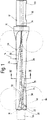
図1はスローアウェイチップとらせん状の冷却媒体通路を備えた穿孔工具の側面図、
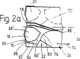
図2a〜2dはそれぞれ互いに90°回転させた切削ヘッドの4つの拡大側面図、
図2eは図2bのE−E線に沿った断面図、
図3は切削ヘッドの平面図、
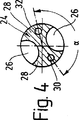
図4は図3のIV−IV線に沿った断面図、
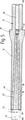
図5は図1〜4の穿孔工具を製作するためのブランクの縦断面図、
図6a〜6hは穿孔工具を製作する際のプロセスを示す概略図、
図7a〜7cは切屑排出方向に波形を付けたらせん状の切屑搬送溝を有する穿孔工具の2つの側面図と1つの断面図、
図8a〜8cは段付きドリルの図7a〜8cと同様な図、
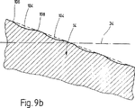
図9a,9bは段状面と波形面を有する切屑搬送溝の切削チップ側の側面を、切屑排出方向に切断して拡大して示す部分図、
図10a〜10hは段状面と波形面の端縁輪郭が異なるように形成された切屑搬送溝の部分図である。
穿孔工具は、実質的に、図示していない工具ホルダーに締付け固定可能であるドリル軸12と、ドリル本体14とからなっている。ドリル軸12は、工具ホルダーのストッパーとして形成されたつば10を備えている。ドリル本体14は、半径方向内側のスローアウェイチップ18と半径方向外側のスローアウェイチップ20のための凹部16を端面側に有する切削ヘッド22と、切削ヘッド22とつば10の間で延びるらせん状の切屑排出部分24を備えている。切屑排出部分24が互いに対向する2つの切屑搬送溝26を備えている。この切屑搬送溝は、その側面が、らせん状に湾曲した2つのリブ28によって画成されている。更に、切屑排出部分24には2つの冷却媒体通路30,32が配置されている。これらの冷却媒体通路はリブと同じ曲率でらせん状に湾曲し、ドリル軸線34に対して一定の傾斜角度βでリブに沿ってらせん状の切屑排出部分24全体にわたって延び、つば10の範囲でドリル軸12内の共通の中央の供給通路36に開口している。中央の供給通路36はドリル軸12内で肉厚のつば10の範囲内まで延びている。供給通路36の流れ横断面は冷却媒体通路30,32の流れ横断面の少なくとも2倍の大きさである。特に図5から判るように、冷却媒体通路30,32は半径方向に互いにずらした接続個所37のところで供給通路36に開口している。リブ28の伸展したブランク状態(図5)では、冷却媒体通路を形成する深穴30,32の中心軸線38,40は、穴中心軸線34またはブランク中心軸線34を通って延びる各々の軸方向平面内にある。この軸方向平面はドリル軸線34の周りに角度α≠180°をなしている(図4参照)。
図示した実施の形態の場合、ドリル本体14に一体に連結された切削ヘッド22は、軸線に対して平行に向いた切屑室60′,60″によって周方向で互いに分離された2つのセグメント部分62を備えている。これらのセグメント部分は半径方向外側が部分円筒状の外周面64によって画成されている。切屑室60′,60″の軸線平行な半径方向の切屑案内面66′,66″の範囲には、スローアウェイチップ18,20が設けられている。これらのスローアウェイチップのすくい面68′,68″は、図示した実施の形態の場合、前記の切屑案内面66′,66″と面一であり、それらの作用切刃70′,70″は端面側で切削ヘッド22から突出している。外側の切削チップ20の切刃70″は、該当するセグメント部分62の外周面64を越えて半径方向に突出し、穴直径を決定する。
更に切削ヘッド22の切屑室60′,60″は、隣接するセグメント部分62に配置されていて切削チップとは反対側の切屑ガイド面72′,72″を備えている。これらの切屑ガイド面は切削チップ側の切屑案内面66′,66″に対向している。
切屑案内面66′,66″は、切屑排出方向74において、自由エッジとして形成された画成エッジ76で終わっている。この画成エッジには、各々、段状に窪んでいる接続面80が接続している。この接続面は、凹形に湾曲する切屑室横断面を広げ、隣接する切屑搬送溝26の側面84に通じている。
切屑ガイド面72′,72″には、各々、ドリル本体14の端面側の尖端の近くまで達する凹部79が、例えばエンドミルカッタによって穿設されている。この凹部は、その端面側の画成エッジ78に、凹形に湾曲し段状に窪んでいる接続面82を備え、切屑排出方向において、滑らかに、隣接する切屑搬送溝26の側面86に通じている。画成エッジ78は、作用切刃70′,70″と、隣接する切削チップ18,20の中央との間の範囲に達するので、切屑室60′,60″の横断面は切削ヘッド22の尖端から切屑搬送溝26まで連続して増大している。
特に図2a,2c,2d,3から判るように、内側の切削チップに所属する切屑案内面66′の範囲に、すくい面区間88が設けられている。このすくい面区間は、互いにオーバーラップする切削チップ18,20の加工範囲内にある、内側の切削チップ18の半径方向外側の切刃部分90にかぶさっている。それによって、切刃部分90と穴との間で穿孔時に形成されたくさび状部分を通って切屑が外周面64の範囲に押しのけられることが防止される。更に、切屑案内面66′の範囲には、切削ヘッド尖端から接続個所近くまで延びる切屑案内面画成部92が設けられている。この切屑案内面画成部は切削チップ18のすくい面68′の平面を越えて切屑室60′の方へ半径方向断面と軸方向断面で段状にあるいはくさび状に突出している(図2d,3)。図2aから判るように、切屑案内面画成部92は、切屑移動方向において、切屑室60′を広げながら、その内側エッジ94が斜め外側に延びている。
図7〜10に示した実施の形態の場合には、切屑搬送溝26の切削チップ側の側面84に、互いに軸方向に間隔をおいて配置された段付き面または波形面104が設けられている。これらの段付き面または波形面は、それらの端部が、ほぼ半径方向に(図7,8,10a,10h)またはドリル中心軸線34に対して斜めに(図10b,10e,10f,10g)に延びる端縁部106,108によって画成されている。段付き面または波形面104は、切削ヘッド側の端縁部106から、切屑排出方向120において局所的に横断面を広げて窪んでおり、該当する溝側面84のらせん傾斜に関して切屑排出方向に先ずは増大しそして減少する傾斜角度を有する(図9a,9b参照)。
図10a〜10hに示した実施の形態の場合には、段付き面または波形面104が、切屑搬送溝26の切削チップ側の側面84における凹部であってその端縁部106,108のところで閉鎖されている(図10b,10c,10d)あるいは半径方向外側の方へ端縁が開放している(図10a,10e〜10h)凹部によって形成されている。その際、それらの凹部は、それらの段付き端縁部または波形端縁部106,108に、例えば楕円形(図10a,10b,10c)、円形(図10d)または長方形(図10e〜10h)の輪郭を有することができる。それらの凹部は互いに間隔をおいて配置してもよいし(図10c〜10h)、それらの端縁部106,108の範囲において互いに直接接続してもよいし(図10a)、互いに交叉してもよい(図10b)。
図8a〜8cに示した実施の形態の場合には、穿孔工具が段付きドリルとして形成されている。ドリル本体14は全部で3つの段付き部分14′,14″,14″′を備えている。これらの段付き部分は軸方向において切削リム110′,110″によって互いに分離され、切屑排出方向に段状に増大する直径を有する。切削リム110′,110″は、半径方向外側が部分円筒状の外周面64′,64″によって画成されて切屑室60″′によって互いに分離された2つのセグメント部分62′と、各々の切削チップ20′を備えていて、その切屑室60″′は、周方向においてセグメント部分62′に接し、ほぼ軸線平行に向けられていて、送り方向と切屑排出方向において隣接する切屑搬送溝26に通じている。切削チップ20′は、セグメント部分62′の凹部内で、ほぼ軸線平行な半径方向の切屑案内面66″′の範囲に配置されていて、切屑案内面66″′に対して面一のすくい面68″′を有する。切削チップ20′は、切削リム110′110″から軸方向に突出する作用切刃70″′を有する。該当する切屑案内面66″′は、切屑排出方向において、接続個所で、隣接する切屑搬送溝26のらせん状に湾曲した側面に接続している。その際、この接続個所には接続面80が設けられている。この接続面は、切屑排出方向において、切屑案内面66″′の画成エッジ76′から、切屑室の横断面を広げながら段状にへこみ、隣接する切屑搬送溝26の一方の側面84に接続している。
図6の概略図から判るように、穿孔工具の製作は次の加工工程で行われる。
円筒状の基礎材料体42Iは、施盤でドリルの輪郭を有するように施削され、つば10に対する円錐状接続部を備える。更に施盤において、供給通路36を形成する中央穴が一方の軸側からつば10の範囲まで穿設される(ブランク42II)。
そして、このようにして準備されたブランク42IIはフライスセンタに締付け固定される。このフライスセンタでは、円板フライス96と型彫りフライス98(図1参照)によって、互いに対向する切屑溝26が縦方向リブ28を残して穿設される。その際、切屑溝は横断面が円形のプロフィルとなり、球状または円環面状の端部を有する。更にフライスセンタにおいて、締付け固定面98がドリル軸に切削加工される(ブランク42III)。図7,8の実施の形態の場合には、更にフライスセンタにおいて、型彫りフライスを用いて、段付き面または波形面104が切屑溝26の切削チップ側の側面に穿設される。
このようにして準備されたブランク42IIIには、同じ挟持固定部であるいは別の穿孔ステーションで、深穴30,32が形成される。これらの深穴は穿孔ヘッド22の端面側の出口個所50,52から縦方向リブ28を通って斜めに供給通路36まで通過する(ブランク42IV)。
このようにして予め製作されたブランク42IVは、ねじれステーションにおいてその両端104,106が締付け固定され、ドリル本体14の切屑排出部分24に沿って摺動可能な誘導コイルによって領域毎に加熱され、締付け固定個所を介して同軸のねじれモーメントが加えられる。その際、切屑排出部分24は穴30,32を含めて徐々にらせん状にねじられる。この場合、ねじり工程中、らせん角度を変更することができる。誘導コイルの背後に配置された冷却ファンにより、その前にねじられた切屑排出部分の区間をそれ以降のねじり工程の際に硬化させることが保証される(ブランク42V)。
ねじり工程の際に発生する寸法エラーを補正するために、ブランク42Vをもう一度施盤で施削してブランク42VIを形成する。
最終加工ステーションでは、切屑案内面66′,66″、切屑ガイド面72′,72″および切削チップ装着部16がフライス加工される(ブランク42VII)。最後に、ヘッド形状がフライス加工されて完成したドリル本体14が形成される。
要約すると次の通りである。本発明は工作機械用穿孔工具に関する。穿孔工具はドリル本体14を備え、このドリル本体は、側面をらせん状に湾曲したリブ28によって画成された2つの切屑搬送溝26を有する。ドリル本体14の端面側には切削ヘッド22が設けられている。この切削ヘッドは、軸方向に向いた互いに対向する切屑室60′,60″によって互いに分離された2つのセグメント部分62と、ドリル軸線34から異なる半径方向距離をおき、互いに部分的にオーバーラップする加工範囲を有し、軸線平行な半径方向の切屑案内面66′,66″の範囲内でセグメント部分の各々の凹部16内に配置された2個の切削チップ18,20とを備えている。切屑案内面66′,66″は接続個所のところで隣接する切屑搬送溝26の側面84に接続している。この場合、切屑室66′,66″の横断面を拡大しながら段状に窪んでいて、隣接する切屑搬送溝26の側面に接続する接続面80が、接続個所の少なくとも1つに設けられている。The present invention relates to a drilling tool for machine tools and a method for producing such a drilling tool.
This type of drilling tool is known. The drilling tool comprises a drill body, the drill body is provided with two chip conveying grooves defined on the sides by spirally curved ribs, and the drilling tool further comprises an end face side of the drill body. The cutting head is arranged in the. The cutting head comprises two segment parts defined radially outward by a partial cylindrical outer surface forming a common outer cylinder, the segment parts being in contact with these segment parts in the circumferential direction. They are separated from each other by chip chambers oriented substantially parallel to the axis, and these chip chambers lead to adjacent chip transport grooves in the chip discharge direction. In addition, the cutting head comprises at least two cutting tips, the cutting tips partially overlapping each other at different radial distances from the drill axis, and the radial chip guides being substantially axially parallel to each other. In each recess of the segment portion within the plane, in particular the rake face is arranged flush with this chip guide surface and each has at least one working cutting edge protruding from the drilling head . In this case, the cutting edge of the outermost cutting tip protrudes in the radial direction from the corresponding outer peripheral surface of the cylindrical shape, and the chip guide surfaces are each spiral in the chip conveying groove adjacent to the chip discharge direction. Connected to the curved side.
By specially orienting the cutting tips that partially overlap in the working range of the cutting edge, the lateral forces generated on the cutting edge in the drilling process are almost offset each other, thereby allowing the workpiece to be substantially guided without any guidance. Can be drilled. The chip chamber extending parallel to the axis in the cutting head and having a triangular cross-section has a relatively steep slope in the direction of chip discharge, and the cross-section is similarly triangular and leads to each of the spiral chip conveying grooves. Yes. The edge of the chip conveying groove is defined by a rib. This rib serves on the one hand for the guidance of the drill within the drill hole and on the other hand for the definition of the chip transport groove. In particular, the chips are pushed outward through the chip conveying grooves under the action of a cooling lubricating medium supplied via the drill body. The formation of relatively wide ribs avoids chips being distributed from the chip transport groove to the outer periphery of the drill body. This is because if it does not, the chips may adhere to the drilling wall and thus to the drilling tool, and there is a risk of destroying the hole or the drilling tool. Another problem is that the chip chamber forms a relatively wide chip chamber having a triangular cross section in the range of the cutting tip displaced radially inward with respect to the outer periphery. The chip chamber is formed in a funnel shape in the chip discharge direction. As a result, the chips may be formed relatively widely when they are generated, and must be pushed into the chip transport groove using a deformation operation. Thereby, most of the shearing energy transferred to the chips in the crushing process is lost in the form of deformation work. In addition, a part of the deformation force is converted into a lateral force, this lateral force will push the drilling tool radially, thereby deteriorating the drilling output and drilling quality.
Starting from this, the underlying problem of the present invention is to develop a drilling tool that guarantees effective and virtually no lateral forces and thus can be used for relatively deep drilling. is there. Another object of the invention is to develop a method for producing a drilling tool according to the invention.
In order to solve this problem, a combination of features described in
The solution according to the invention is based on the recognition that in particular the deformation of the chip, which compresses the chip and increases the lateral force, must be avoided in the area of the chip chamber and in the area of the subsequent chip transport groove. Yes. To achieve this, the present invention proposes the following features:
A drilling tool for a machine mechanism,
Comprising a drill body, the drill body comprising at least two chip conveying grooves defined on the sides by helically curved ribs;
The cutting head further comprises a cutting head disposed on the end face side of the drill body, the cutting head comprising at least two segment portions defined radially outward by a partially cylindrical outer peripheral surface, the segment portions being Are separated from each other by chip chambers that are in contact with these segment portions in the circumferential direction and are oriented substantially parallel to the axis, and these chip chambers communicate with adjacent chip conveying grooves in the chip discharge direction, and further the cutting head , Comprising at least two cutting tips arranged in a recess in each of the segment portions,
The drill body comprises a drill shaft at its end opposite the cutting head, the drill shaft is not provided with ribs, the drill shaft including a central coolant supply passage;
A cooling medium passage is arranged in the rib of the drill body.These cooling medium passages are spirally curved with the same curvature as the ribs,
In the drilling tool,
The coolant passage isCut offExtending from the cutting head over the entire length of the rib at a constant inclination with respect to the drilling tool axis, so that the coolant channel opens into the central coolant supply channel in the region of the drill shaft without the ribs WhatAnd a chip chamber is defined by the respective cutting guide surfaces substantially parallel to the axis provided with the cutting tips and the respective chip guide surfaces on the side surfaces, the chip guide surface and / or the chip guide surface being , In the adjacent side surface of the adjacent chip conveying groove, it is recessed and moved in a step shape while expanding the cross section of the chip chamber.
Due to the connecting surface in the range of the chip guide surface and the chip guide surface, a feed force that improves chip discharge is transmitted to the chip generated in the chip chamber when moving to the chip transport groove, and in this case, chip deformation Or chip compression does not occur.
In the case of a drilling tool formed as a stepped drill, the drill body comprises at least two stepped portions separated from each other in the axial direction by a cutting rim, the stepped portions being stepped in the chip discharge direction. Has an increasing diameter. In this case, the cutting rim includes two segment portions defined radially outward by a partial cylindrical outer peripheral surface, and these segment portions are in contact with these segment portions in the circumferential direction and are substantially parallel to the axis. Are separated from each other by chip chambers, which lead to adjacent chip conveying grooves in the direction of chip discharge, and further the cutting rim comprises at least one cutting tip, which has a substantially axial line. In the area of the parallel radial chip guide surface, it is arranged in a recess in one of the segment parts, in particular so that this chip guide surface and the rake face are flush with each other, protruding axially beyond the cutting rim At least one working cutting edge, wherein the chip guide surface is spirally connected to the adjacent chip conveying groove at the connecting point in the chip discharging direction. A connecting surface is arranged at this connection point, and this connecting surface is recessed in a step shape by expanding the cross section of the chip chamber from the defined edge of the chip guide surface in the chip discharging direction. It is connected to one side surface of the adjacent chip conveyance groove.
The stepped connection surface preferably extends over the entire width of the chip guide surface and / or chip guide surface and is concavely curved in the chip discharge direction. Therefore, the connection surface smoothly transitions to the side surface of the chip conveyance groove.
In order to improve chip discharge, according to another or advantageous embodiment of the invention, a plurality of stepped or corrugated edges extending radially or obliquely with respect to the drilling tool axis are at least provided for chip transport. A stepped surface that is arranged on the side surface of the groove on the cutting tip side with an interval in the axial direction, and the stepped edge or corrugated edge is recessed in the chip discharging direction to locally expand the cross section of each chip conveying groove Or it consists of a corrugated surface. In this case, each stepped or corrugated surface is defined by other stepped or corrugated edges extending radially or diagonally with respect to the drilling tool axis at the end of the chip discharge side. The stepped or corrugated surface has an inclination angle that first increases and decreases with respect to the helical inclination of the corresponding groove side in the chip discharge direction. The stepped or corrugated surface is formed by a recess on the side of the chip tip of the chip conveying groove, which is closed at the stepped or corrugated edge or open radially outward on one side. is doing. The recess has an arbitrary contour, in particular an elliptical, circular or rectangular contour at its stepped or corrugated edge. Due to the stepped surface or the corrugated surface, a feed force desirable for chip discharge is transmitted to the chip within the chip transport groove, and at this time, the chip is not deformed or compressed.
According to an advantageous or alternative embodiment of the invention, the side of the chip conveying groove is close to its outer edge, in cross-section, in order to prevent chips from exiting the chip conveying groove into the outer periphery of the rib, It is proposed to make an angle smaller than 90 °, in particular from 0 to 30 °. For this purpose, it is advantageous if the cross section of the chip conveying groove has a partial circular shape, in particular a semicircular shape. In this case, the outline of the cross section of the chip conveying groove extends linearly toward the outer edge in the range of at least one side surface.
In order to improve chip discharge, the chip chamber is relatively short to the connection point in the area of the cutting tip. Therefore, the curved defined edge has an interval that varies from the edge of the recess for the cutting tip over the length of the edge, which corresponds to 0.1 to 0.4 times the diameter of the outer surface of the cutting tip at the narrowest point. Then it is a good purpose. The partial cylindrical outer peripheral surface of the segment part and the partial cylindrical outer peripheral surface of the rib preferably form a common outer peripheral cylinder interrupted by the chip chamber and the chip conveying groove.
An advantageous variant solution or alternative variant according to the invention in order to prevent chips from being pushed out of the chip chamber into the outer peripheral surface of the drill through the intermediate chambers that remain in the region of the overlapping cutting edges. In the solution, a cutting guide surface section is proposed, and this chip guide surface section covers the cutting edge portions in the processing range that overlap each other. This problem occurs particularly in the cutting chamber attached to the cutting tip that is displaced radially inward. Therefore, the chip guide surface section covers the cutting edge portion on the radially outer side of the innermost cutting tip in the radial direction. However, basically, the chip guide surface section can be covered with the cutting edge portion on the radially inner side of the radially outermost cutting tip. Thereby, the gaps present there can be cross-linked.
In an advantageous or alternative variant solution of the invention, the chip guide surface is defined on the radially outer side which is connected to the part cylindrical outer peripheral surface and extends from the cutting head tip or cutting rim tip to the vicinity of the connection point. Is provided. The chip guide surface defining portion protrudes toward the chip chamber from the plane of the rake face of the cutting tip shifted radially inward with respect to the outer periphery. Thereby, it is prevented that the chips generated by the cutting blade are pushed away to the outer peripheral surface of the partial cylindrical shape. The chip guide surface defining portion has a radial cross section and protrudes stepwise or wedge-shaped beyond the plane of the cutting edge rake face. In addition to this, the chip guide surface defining portion has an axial cross section, protrudes in a stepped shape or wedge shape beyond the plane of the cutting edge rake face, and diffuses in the chip discharging direction to widen the chip chamber. Therefore, chip discharge to the adjacent chip conveyance groove is facilitated.
In order to allow the drill body to accommodate as deep a chip conveying groove as possible with a large chip passage cross-sectional area, the following is advantageous. That is, the drill body includes a drill shaft that includes a central coolant supply passage and is not provided with a rib, and a coolant passage that leads to a cutting head or a cutting rim of the drill body is disposed in the rib. In this case, these coolant passages are spirally curved with the same curvature as the ribs, extend over the entire length of the ribs at a constant inclination angle with respect to the drilling tool axis, and are not provided with a drill shaft In this range, it opens to the central coolant supply passage. In order to facilitate the manufacture, the cooling medium passage forms a straight deep hole that is inclined obliquely with respect to the drilling tool axis in the unfolded state of the rib. The inclination angle of the deep hole with respect to the drilling tool axis is 1-8 °, depending on the diameter and length of the drill body. The deep hole axis is preferably in an axial plane extending through the drilling tool axis with the ribs deployed. In this case, the axial plane including both deep holes forms an angle that is not 180 ° around the drilling tool axis. The angle between the axial planes is preferably 155 to 175 °. By this means, a continuous change of the cross-section, thereby increasing the strength and improving the vibration damping effect is achieved. The mass distribution across the cross section is also affected by the angle between the axial planes. With the embodiment according to the present invention and the arrangement structure of the coolant passage, a deep chip groove can be provided over the entire length of the chip discharge portion. The cooling medium holes are desirably arranged in a flow manner. When oriented obliquely with respect to the drilling tool axis, a flow assisted by centrifugal force is produced in the direction of the outlet location.
In order to produce a drilling tool according to the invention, the following method steps are proposed:
The base material body is machined to the contour of the drilling tool, forming a blank body having a plurality of stepped portions of rotational symmetry, cylindrical in sections and possibly different diameters;
-Two chip conveying grooves provided opposite to each other and defined by the end portions on both axial sides are formed or cut into a cylindrical section (chip discharging portion) of the blank body, and these chip conveying grooves Is defined by the remaining longitudinal ribs,
-Two chip chambers defined on the side surfaces by each chip guide surface and each chip guide surface substantially parallel to the axis are formed or cut at the end of the blank body on the cutting head side or the cutting rim side. The chip guide surface and / or chip guide surface of the chip chamber intersects the side of the adjacent chip conveying groove in the range of the end portion on the cutting head side or the cutting rim side or in the cutting head, Forming a connection surface that is recessed in steps,
The chip conveying groove is first shaped or cut into the blank body or into its stepped part in the form of longitudinal grooves parallel to the axis;
-Before or after forming or cutting, deep holes for coolant passages are drilled in the area of the linear ribs;
-Drill shafts without ribs obliquely with respect to the cylindrical central axis of the blank body from the location where these deep holes are decentered on the end face of the blank end on the cutting head side or cutting rim side Extending towards the bag hole for the central coolant supply passage in the inside, through the bottom of this bag hole,
The prefabricated blank has clamping and fixing points arranged axially spaced from each other and is heated to a preset temperature in a ribbed area between these clamping and fixing points; A coaxial torsional moment is applied at the clamping and fixing points, and the heating region is plastically twisted in a helical manner by a predetermined angle,
In that case, the twist angle is varied to form a helical pitch that increases continuously or stepwise in the axial direction in the region of the ribs.
In this case, the chip conveying groove is drilled in the blank body using a disc mill and / or die milling, in this case a concave connection that matches the annular face of the disc mill and / or the spherical shape of the die milling mill A surface occurs at the end. Thereby, a chip groove whose cross section has a partial circle or other inner contour can be machined. The chip conveying groove ends linearly toward the outer edge at least on the groove side surface on the cutting tip side. In order to increase the strength of the drill body, in particular near the clamping and clamping part of the drill shaft, in an advantageous embodiment of the invention, the longitudinal grooves are machined into the cylindrical body so that the depth is shallow in the chip discharge direction. It is suggested that In order to be able to form as deep a groove as possible reaching near the drill axis, a chip conveying groove is first drilled in the blank body in the form of longitudinal grooves parallel to the axis, before or after the cutting process, A deep hole is drilled in the range of the straight ribs, and this deep hole is inclined with respect to the cylindrical axis of the blank body from the eccentric part arranged on the end surface of the blank end on the cutting head side or the cutting rim side. It is advantageous if it extends towards the central hole in the drill shaft without ribs and penetrates the bottom of this hole. The blanks manufactured in advance in this way are sandwiched and fixed places arranged at an axial distance from each other, and are heated to a set temperature in a ribbed region between these sandwiched and fixed parts, and the sandwiched and fixed parts thereof. A coaxial torsional moment is applied at the point where it is helically twisted at a predetermined angle in the heated area.
In a preferred embodiment of the invention, the blank is twisted in the region between the clamping points with a heating zone that changes axially continuously or stepwise. Thereby, the twist angle can be changed, and a variable helical pitch can be formed in the axial direction.
In another advantageous embodiment of the invention, a stepped or corrugated surface, which is spaced axially from one another at least on the groove side surface on the cutting tip side and defined by a substantially radial edge, in particular, It is cut by mold carving milling. In this case, it is advantageous if this takes place before the helical twisting of the corresponding blank.
Next, the present invention will be described in detail with reference to the drawings.
1 is a side view of a drilling tool with a throw-away tip and a helical coolant passage,
2a to 2d are four enlarged side views of the cutting heads rotated 90 ° relative to each other,
2e is a cross-sectional view taken along line EE of FIG.
FIG. 3 is a plan view of the cutting head,
4 is a cross-sectional view taken along line IV-IV in FIG.
FIG. 5 is a longitudinal sectional view of a blank for producing the drilling tool of FIGS.
Figures 6a to 6h are schematic diagrams illustrating the process in making a drilling tool;
7a to 7c are two side views and one cross-sectional view of a drilling tool having a spiral chip conveying groove corrugated in the chip discharge direction;
8a-8c are views similar to FIGS. 7a-8c of a step drill,
9a and 9b are partial views showing the side surface on the cutting tip side of the chip conveying groove having a stepped surface and a corrugated surface by cutting in the chip discharging direction and expanding.
10a to 10h are partial views of the chip conveying groove formed so that the edge contours of the stepped surface and the corrugated surface are different.
The drilling tool substantially comprises a
In the case of the illustrated embodiment, the cutting
Furthermore, the
The chip guide surfaces 66 ′, 66 ″ terminate in a defined
The chip guide surfaces 72 ′ and 72 ″ are each provided with a
As can be seen in particular from FIGS. 2 a, 2 c, 2 d, 3, a
In the case of the embodiment shown in FIGS. 7 to 10, a stepped surface or
In the case of the embodiment shown in FIGS. 10a to 10h, the stepped surface or
In the case of the embodiment shown in FIGS. 8a to 8c, the drilling tool is formed as a stepped drill. The
As can be seen from the schematic diagram of FIG. 6, the drilling tool is manufactured in the following processing step.
Cylindrical
And the blank 42 prepared in this wayIIIs fastened and fixed to the milling center. In this milling center, the
A blank 42 previously produced in this way.IVAre twisted and fixed at both ends 104 and 106 at the torsion station, heated region by area by an induction coil slidable along the
In order to correct dimensional errors that occur during the twisting process, the blank 42VCut again with a lathe and blank 42VIForm.
At the final processing station, the chip guide surfaces 66 ′, 66 ″, the chip guide surfaces 72 ′, 72 ″ and the cutting
In summary: The present invention relates to a drilling tool for machine tools. The drilling tool comprises a
Claims (12)
ドリル本体(14)を具備し、このドリル本体(14)が、らせん状に湾曲したリブ(28)によって側面(84,86)を画成された少なくとも2つの切屑搬送溝(26)を備え、
更に、ドリル本体(14)の端面側に配置された切削ヘッド(22)を具備し、この切削ヘッド(22)が、部分円筒状の外周面(64)によって半径方向外側を画成された少なくとも2つのセグメント部分(62)を備え、これらのセグメント部分(62)が、周方向においてこれらのセグメント部分(62)に接してほぼ軸線平行に向いた切屑室(60′,60″)によって互いに分離されていて、これらの切屑室(60′,60″)が、切屑排出方向(74)において隣接する切屑搬送溝(26)に通じていて、更に切削ヘッド(22)が、セグメント部分(62)の各々の凹部(16)内に配置された少なくとも2つの切削チップ(18,20)を備え、
ドリル本体(14)が、切削ヘッド(22)と反対のその端部にドリル軸(12)を備え、このドリル軸(12)にはリブが設けられてなく、このドリル軸(12)が中央の冷却媒体供給通路(36)を含んでいて、
ドリル本体(14)のリブ(28)内には冷却媒体通路(30,32)が配置されていて、これらの冷却媒体通路(30,32)が、リブ(28)と同じ曲率でらせん状に湾曲されている、
前記穿孔工具において、
冷却媒体通路(30,32)が、切削ヘッド(22)から、穿孔工具軸線(34)に対して一定の傾斜角度(β)でリブ(28)の全長にわたって延びていて、それによって冷却媒体通路(30,32)が、リブの設けられていないドリル軸(12)の範囲において中央の冷却媒体供給通路(36)に開口していること、及び、
切屑室(60′,60″)が、互いに側面において、切屑チップ(18,20)を備えたほぼ軸線平行な各々の切屑案内面(66′,66″)と、各々の切屑ガイド面(72′,72″)とによって画成されていて、切屑案内面(66′,66″)および/または切屑ガイド面(72′,72″)が、隣接する切屑搬送溝(26)の隣接する側面(84,86)に、切屑室(60′,60″)の横断面を広げながら段状に窪んで移行していること
を特徴とする穿孔工具。A machine tool drilling tool,
Comprising a drill body (14), the drill body (14) comprising at least two chip transport grooves (26) defined on the sides (84, 86) by helically curved ribs (28);
Furthermore, it has a cutting head (22) arranged on the end face side of the drill body (14), and this cutting head (22) is defined at least radially outside by a partially cylindrical outer peripheral surface (64). Comprising two segment parts (62), which are separated from each other by a chip chamber (60 ', 60 ") that is generally axially parallel to and in contact with these segment parts (62) These chip chambers (60 ', 60 ") communicate with the chip transport groove (26) adjacent in the chip discharge direction (74), and the cutting head (22) further includes a segment portion (62). At least two cutting tips (18, 20) disposed in each recess (16) of
The drill body (14) is provided with a drill shaft (12) at its end opposite to the cutting head (22), the drill shaft (12) is not provided with ribs, and the drill shaft (12) is centered. A cooling medium supply passage (36) of
Cooling medium passages (30, 32) are disposed in the rib (28) of the drill body (14) , and these cooling medium passages (30, 32) are spiral with the same curvature as the rib (28). Curved,
In the drilling tool,
Coolant passages (30, 32) is, from the switching cutting head (22), extend over the entire length of the rib (28) at a constant inclination angle (beta) with respect to the drilling tool axis (34), whereby the cooling medium The passages (30, 32) open into the central coolant supply passage (36) in the region of the drill shaft (12) without ribs ; and
The chip chambers (60 ', 60 ") have, on their sides, respective chip guide surfaces (66', 66") that are substantially axially parallel with chip tips (18, 20) and each chip guide surface (72). ′, 72 ″), and the chip guide surface (66 ′, 66 ″) and / or the chip guide surface (72 ′, 72 ″) are adjacent side surfaces of the adjacent chip conveying groove (26). A drilling tool characterized in that, at (84, 86), the chip chamber (60 ', 60 ") is transferred in a stepped manner while expanding the cross section of the chip chamber (60', 60") .
− 基礎材料体(42I)が、穿孔工具の輪郭へと施削され、回転対称で区間毎に円筒状であり場合によっては異なる直径の複数の段状部分を有するブランク本体(42II)を形成し、
− 互いに対向して設けられて軸方向両側が末端部(100,102)によって画成された2つの切屑搬送溝(26)が、ブランク本体(42II)の円筒状の区間(切屑排出部分(24))に成形または切削加工され、これらの切屑搬送溝(26)の側面(84,86)が、残りの縦方向のリブ(28)によって画成されていて、
− ほぼ軸線平行な各々の切屑案内面(66′,66″)と各々の切屑ガイド面(72′,72″)とによって互いに側面において画成された2つの切屑室(60′,60″)が、ブランク本体(42VII)の切削ヘッド側または切削リム側の端部に成形または切削加工され、切屑室(60′,60″)の切屑案内面(66′,66″)および/または切屑ガイド面(72′,72″)が、切削ヘッド側または切削リム側の末端部(100)の範囲において、または切削ヘッド内において、隣接する切屑搬送溝(26)の側面(84,86)と交わり、画成縁部と段状に窪んでいる接続面(80,82)とを形成し、
− 切屑搬送溝(26)が、先ず、軸線平行な縦方向溝の形で、ブランク本体(42III)にまたはその段状部分に成形または切削加工され、
− 成形または切削加工の前または後で、直線的なリブ(28)の範囲に冷却媒体通路(30,32)のための深穴が穿設され、
− これらの深穴が、切削ヘッド側または切削リム側のブランク端部の端面に偏心させて配置された個所から、ブランク本体(42IV)の円筒中心軸線(34)に対して斜めに、リブの設けられていないドリル軸(12)内の中央の冷却媒体供給通路(36)のための袋穴の方へ延び、この袋穴の底を貫通し、
− このようにして予め製作されたブランク(42V)が、互いに軸方向間隔をおいて配置された挟持固定個所(104,106)を有し、これらの挟持固定個所(104,106)の間にあるリブ付き領域において予め設定した温度に加熱され、それらの挟持固定個所(104,106)において同軸のねじりモーメントが加えられ、その加熱領域において予め定めた角度だけらせん状に塑性的にねじられ、
− その際には、ねじり角度が変えられ、リブ(28)の範囲において軸方向に連続的にまたは段階的に増大するらせんピッチを形成されること。A method for making a drilling tool according to any one of the preceding claims, comprising the following steps:
- the basic material body (42 I) is, is lathe turned to the contour of the drilling tool, a blank body (42 II) having a plurality of stepped portions of different diameters and in some cases a cylindrical for each section in rotational symmetry Forming,
- face each other are provided in the axial direction on both sides end portions (100, 102) of two chip transport grooves defined by (26), the cylindrical section of the blank body (42 II) (chip discharge portion ( 24)), the side surfaces (84, 86) of these chip conveying grooves (26) are defined by the remaining longitudinal ribs (28),
-Two chip chambers (60 ', 60 ") defined laterally by each chip guide surface (66', 66") and each chip guide surface (72 ', 72 ") substantially parallel to the axis. Is formed or cut at the end of the blank body (42 VII ) on the cutting head side or the cutting rim side, and the chip guide surface (66 ', 66 ") and / or the chip in the chip chamber (60', 60"). Guide surfaces (72 ', 72 ") in the region of the end (100) on the cutting head side or cutting rim side, or in the cutting head, with the side surfaces (84, 86) of the adjacent chip conveying groove (26). Intersect to form a defined edge and a stepped recess (80, 82),
The chip conveying groove (26) is first molded or cut into the blank body (42 III ) or into its stepped part in the form of longitudinal grooves parallel to the axis;
A deep hole for the coolant passage (30, 32) is drilled in the area of the linear rib (28) before or after forming or cutting,
-These deep holes are ribbed obliquely with respect to the cylindrical central axis (34) of the blank body (42 IV ) from the location where they are eccentrically arranged on the end face of the blank end on the cutting head side or the cutting rim side. Extending toward the bag hole for the central coolant supply passage (36) in the drill shaft (12) not provided with, and penetrating through the bottom of the bag hole,
The blank (42 V ) thus produced in advance has clamping and fixing points (104, 106) arranged axially apart from each other, between these clamping and fixing points (104, 106). In the ribbed region at a predetermined temperature, a coaxial torsional moment is applied at the clamping and fixing points (104, 106), and the heating region is plastically twisted in a helical manner by a predetermined angle. ,
In that case, the twist angle is varied to form a helical pitch which increases continuously or stepwise in the axial direction in the region of the rib (28).
Applications Claiming Priority (3)
| Application Number | Priority Date | Filing Date | Title |
|---|---|---|---|
| DE19607594.7 | 1996-02-29 | ||
| DE19607594 | 1996-02-29 | ||
| PCT/EP1997/000901 WO1997031742A2 (en) | 1996-02-29 | 1997-02-26 | Drilling tool for machine tools and method of producing the same |
Publications (2)
| Publication Number | Publication Date |
|---|---|
| JP2000508589A JP2000508589A (en) | 2000-07-11 |
| JP3801210B2 true JP3801210B2 (en) | 2006-07-26 |
Family
ID=7786721
Family Applications (1)
| Application Number | Title | Priority Date | Filing Date |
|---|---|---|---|
| JP53058097A Expired - Lifetime JP3801210B2 (en) | 1996-02-29 | 1997-02-26 | Drilling tool for machine tool and method of manufacturing this drilling tool |
Country Status (19)
| Country | Link |
|---|---|
| US (1) | US6030155A (en) |
| EP (1) | EP0883455B1 (en) |
| JP (1) | JP3801210B2 (en) |
| KR (1) | KR100485987B1 (en) |
| CN (1) | CN1076238C (en) |
| AT (1) | ATE208675T1 (en) |
| AU (1) | AU1876697A (en) |
| BR (1) | BR9707896A (en) |
| CA (1) | CA2245802C (en) |
| CZ (1) | CZ292324B6 (en) |
| DE (2) | DE19707549B4 (en) |
| DK (1) | DK0883455T3 (en) |
| ES (1) | ES2166527T3 (en) |
| HK (1) | HK1012497A1 (en) |
| HU (1) | HU222128B1 (en) |
| IL (1) | IL125688A (en) |
| PL (1) | PL183254B1 (en) |
| PT (1) | PT883455E (en) |
| WO (1) | WO1997031742A2 (en) |
Families Citing this family (55)
| Publication number | Priority date | Publication date | Assignee | Title |
|---|---|---|---|---|
| AUPP569198A0 (en) * | 1998-09-03 | 1998-10-01 | Anca Pty Ltd | Grinding of cutting tools with wavy cutting edges |
| ATE265917T1 (en) * | 2000-03-03 | 2004-05-15 | Johann Eberhard Ges M B H | DRILLS, ESPECIALLY FORSTNER DRILLS OR ARTWORK DRILLS |
| US6644899B2 (en) | 2000-03-03 | 2003-11-11 | Johann Eberhard Gesellschaft M.B.H. | Drill bit and process of producing a drill bit with improved cutting edges |
| FR2808462B1 (en) * | 2000-05-05 | 2002-09-20 | Diager | DRILLING DRILL |
| US9199315B2 (en) * | 2000-06-02 | 2015-12-01 | Kennametal Inc. | Twist drill and method for producing a twist drill which method includes forming a flute of a twist drill |
| DE10027544A1 (en) * | 2000-06-02 | 2001-12-13 | Kennametal Inc | Drill tip for a twist drill and method for producing a flute in the area of a drill tip for a twist drill |
| IL145499A0 (en) * | 2001-09-17 | 2002-06-30 | Hanita Metal Works Ltd | Milling cutter with coolant conduits |
| JP4287273B2 (en) * | 2001-09-24 | 2009-07-01 | アプライド メディカル リソーシーズ コーポレイション | Bladeless obturator |
| US7306411B2 (en) * | 2002-09-03 | 2007-12-11 | Mitsubishi Materials Corporation | Drill with groove width variation along the drill and double margin with a thinning section at the tip |
| KR100556681B1 (en) * | 2003-04-28 | 2006-03-07 | 대구텍 주식회사 | tool holder assembly for multifunctional machining |
| WO2006001819A1 (en) * | 2003-11-12 | 2006-01-05 | Donald Nadler | Anchoring drill bit, system and method of anchoring |
| DE10353514A1 (en) * | 2003-11-14 | 2005-06-23 | Heule, Ulf | Drilling plate with clamping attachment in a base body |
| JP4466827B2 (en) | 2003-12-11 | 2010-05-26 | 日本電気株式会社 | ANTENNA DEVICE AND WIRELESS COMMUNICATION DEVICE |
| WO2005083536A1 (en) * | 2004-02-10 | 2005-09-09 | Carl Zeiss Smt Ag | Program-controlled nc-data generating method with correction data |
| EP1695793A1 (en) * | 2005-02-25 | 2006-08-30 | Rollomatic S.A. | Machine for producing a bit of a drill and the drill |
| IL174775A (en) | 2006-04-04 | 2013-06-27 | Hanita Metal Works Ltd | Face milling cutter |
| US7546786B2 (en) * | 2006-04-04 | 2009-06-16 | Kennametal Inc. | Toolholder with chip ejection segment thereupon |
| DE102006027552B4 (en) * | 2006-06-14 | 2011-06-01 | Audi Ag | Drilling tool, in particular for metallic materials |
| NO330162B1 (en) * | 2006-06-28 | 2011-02-28 | Teeness Asa | Container for insertion into a tool holder, a tool holder and a system |
| DE102006049088A1 (en) * | 2006-10-13 | 2008-04-24 | Kennametal Inc. | Modular drilling tool and method for its manufacture |
| JP4976181B2 (en) * | 2006-12-25 | 2012-07-18 | 住友電工ハードメタル株式会社 | Tip placement method for throw-away drills |
| US8727673B2 (en) * | 2007-01-18 | 2014-05-20 | Kennametal Inc. | Cutting insert with internal coolant delivery and surface feature for enhanced coolant flow |
| DE102007023168A1 (en) * | 2007-05-20 | 2008-11-27 | Gühring Ohg | Rotary drivable cutting tool |
| DE102007023167A1 (en) * | 2007-05-20 | 2008-11-27 | Gühring Ohg | Machining tool |
| SE531188C2 (en) * | 2007-05-29 | 2009-01-13 | Sandvik Intellectual Property | Drill body for chip separating machining |
| CN101879622B (en) * | 2007-07-12 | 2012-08-22 | 本田技研工业株式会社 | Drill |
| DE102007042279A1 (en) * | 2007-09-06 | 2009-03-12 | Komet Group Holding Gmbh | Drilling tool for machine tools and method for its production |
| DE102007042280A1 (en) * | 2007-09-06 | 2009-03-12 | Komet Group Holding Gmbh | Drilling tool for machine tools and method for its production |
| SE533679C2 (en) * | 2009-04-07 | 2010-11-30 | Sandvik Intellectual Property | Solid step drill |
| CA2764129C (en) | 2009-06-02 | 2013-10-15 | Tungaloy Corporation | Indexable drill and drill body |
| US9724766B2 (en) | 2010-01-13 | 2017-08-08 | Irwin Industrial Tool Company | Hole cutter with multiple fulcrums |
| DE102010006797B4 (en) * | 2010-02-04 | 2011-12-22 | Kennametal Inc. | drilling |
| GB201015541D0 (en) * | 2010-09-17 | 2010-10-27 | Element Six Ltd | Twist drill assembly |
| DE102010041164B4 (en) * | 2010-09-22 | 2022-01-27 | Adolf Würth Gmbh & Co Kg | Method of making a drill |
| CN102261225A (en) * | 2011-08-08 | 2011-11-30 | 平顶山市中矿机械制造有限公司 | Multifunctional outburst-prevention drill rod |
| US9656331B2 (en) | 2011-11-15 | 2017-05-23 | Kennametal Inc. | System and method for simultaneously forming flutes in solid carbide tools |
| DE102012212440B4 (en) * | 2012-07-16 | 2022-04-14 | Kennametal Inc. | Drilling tool, in particular for machining components made from a titanium alloy, and method for machining such a component |
| CN103071818B (en) * | 2013-02-16 | 2015-04-15 | 无锡蠡湖叶轮制造有限公司 | Corrugated oblique-neck one-step molding cutter |
| CN104107939A (en) * | 2013-04-19 | 2014-10-22 | 苏州文鼎模具有限公司 | Internally-cooled drill |
| DE102014108219B4 (en) * | 2014-06-12 | 2020-12-17 | Kennametal Inc. | Rotary tool and method for producing a rotary tool |
| CN105458353B (en) * | 2015-12-15 | 2018-12-11 | 中国民航大学 | A kind of electroplated diamond cutter for fibre reinforced composites drilling |
| IL246227B (en) * | 2016-06-15 | 2021-07-29 | Hanita Metal Works Ltd | Fluted cutting tool configuration and method therefor |
| CN107812985A (en) * | 2016-09-11 | 2018-03-20 | 上海名古屋精密工具股份有限公司 | Aperture knife tool and its application |
| GB2562730B (en) * | 2017-05-22 | 2020-07-01 | Gkn Aerospace Sweden Ab | Cooled drill |
| CN107775059A (en) * | 2017-11-28 | 2018-03-09 | 宝鸡文理学院 | Spiral bit for deep hole machining |
| JP7164101B2 (en) * | 2018-02-06 | 2022-11-01 | 国立大学法人東海国立大学機構 | Drills and drilling equipment |
| CN112077370A (en) | 2019-06-13 | 2020-12-15 | 肯纳金属印度有限公司 | Indexable drill insert |
| JP6835194B1 (en) * | 2019-12-12 | 2021-02-24 | 株式会社タンガロイ | Drilling tool |
| CN111495884A (en) * | 2020-05-13 | 2020-08-07 | 南昌航空大学 | Laser cleaning device and method for inert gas auxiliary cleaning |
| CN112658307A (en) * | 2020-12-15 | 2021-04-16 | 广西玉柴机器股份有限公司 | Method for machining through-nail hole hollowed in middle |
| CN113441761B (en) * | 2021-06-22 | 2023-04-18 | 哈尔滨瀚成科技有限公司 | Preparation method of inner-cooling drill bit, inner-cooling drill bit and heating device |
| US11865629B2 (en) | 2021-11-04 | 2024-01-09 | Kennametal Inc. | Rotary cutting tool with high ramp angle capability |
| EP4197677A1 (en) * | 2021-12-15 | 2023-06-21 | AB Sandvik Coromant | Drill with improved chip evacuation |
| EP4201561A1 (en) | 2021-12-21 | 2023-06-28 | Seco Tools Ab | Drill body of an indexable insert drill and indexable insert drill comprising such a drill body |
| CN116213781B (en) * | 2023-05-06 | 2023-07-14 | 太原工具厂有限责任公司 | Indexable shallow hole drill assisting chip removal |
Family Cites Families (19)
| Publication number | Priority date | Publication date | Assignee | Title |
|---|---|---|---|---|
| US1747117A (en) * | 1927-04-01 | 1930-02-11 | Dayton W Klein | Method of making multiple diameter cut tools |
| US2322894A (en) * | 1939-06-29 | 1943-06-29 | Rustless Iron & Steel Corp | Twist drill |
| AT279998B (en) * | 1967-05-09 | 1970-03-25 | Rohde & Doerrenberg | Process for manufacturing twist drills or similar tools as well as twist drills manufactured according to the process |
| CH625443A5 (en) * | 1977-11-21 | 1981-09-30 | Grob Ernst Fa | Drill with square indexable carbide inserts |
| DE2808866C2 (en) * | 1978-03-02 | 1982-10-07 | Komet Stahlhalter- Und Werkzeugfabrik Robert Breuning Gmbh, 7122 Besigheim | Drilling tool for holes in solid metal material |
| DE2945635A1 (en) * | 1979-11-12 | 1981-05-21 | Rohde & Dörrenberg, 4000 Düsseldorf | Helically fluted drill contg. coolant ducts - has cutting bits at tip on seating faces at acute angle to helix direction near tip |
| DE3500602A1 (en) * | 1985-01-10 | 1986-07-10 | Bernhard 4500 Osnabrück Mönkediek | DRILLING TOOL |
| DE8536123U1 (en) * | 1985-12-21 | 1987-04-16 | Komet Stahlhalter- Und Werkzeugfabrik Robert Breuning Gmbh, 7122 Besigheim, De | |
| JP2603993B2 (en) * | 1988-03-11 | 1997-04-23 | 俊明 細井 | Drill |
| US4904130A (en) * | 1989-01-11 | 1990-02-27 | Gorman Jeremy W | Cutting tools with depth indication |
| SE502255C2 (en) * | 1991-12-16 | 1995-09-25 | Sandvik Ab | Drill with chip channels, comprising a first and a second chip feeding zone, of different cross sections |
| DE4231381A1 (en) * | 1992-09-19 | 1994-03-24 | Mitsubishi Materials Corp | drill |
| DE4239311C2 (en) * | 1992-11-23 | 1996-04-18 | Guehring Joerg Dr | Drills, especially pointed drilling tools with exchangeable cutting inserts |
| DE4241140A1 (en) * | 1992-12-07 | 1994-06-09 | Krupp Widia Gmbh | Chip cutting tool with cutting insert(s) - has swarf disposed face outside cutting insert with processed surface |
| SE470547B (en) * | 1992-12-10 | 1994-08-01 | Sandvik Ab | Drill with cooling ducts and means for making drill |
| US5295422A (en) * | 1993-04-23 | 1994-03-22 | Jessie Chow | Wrench having a greater driving strength |
| SE508466C2 (en) * | 1993-09-14 | 1998-10-12 | Seco Tools Ab | Drill |
| DE4415491A1 (en) * | 1994-05-02 | 1995-11-09 | Krupp Widia Gmbh | Machining tool, esp. cutting insert |
| SE509262C2 (en) * | 1995-03-02 | 1998-12-21 | Sandvik Ab | Drill with cooling ducts and means for making them |
-
1997
- 1997-02-26 DK DK97905084T patent/DK0883455T3/en active
- 1997-02-26 AU AU18766/97A patent/AU1876697A/en not_active Abandoned
- 1997-02-26 PT PT97905084T patent/PT883455E/en unknown
- 1997-02-26 HU HU9900996A patent/HU222128B1/en not_active IP Right Cessation
- 1997-02-26 DE DE19707549A patent/DE19707549B4/en not_active Expired - Fee Related
- 1997-02-26 JP JP53058097A patent/JP3801210B2/en not_active Expired - Lifetime
- 1997-02-26 CA CA002245802A patent/CA2245802C/en not_active Expired - Fee Related
- 1997-02-26 EP EP97905084A patent/EP0883455B1/en not_active Expired - Lifetime
- 1997-02-26 BR BR9707896A patent/BR9707896A/en not_active IP Right Cessation
- 1997-02-26 IL IL12568897A patent/IL125688A/en not_active IP Right Cessation
- 1997-02-26 DE DE59705390T patent/DE59705390D1/en not_active Expired - Lifetime
- 1997-02-26 CZ CZ19982366A patent/CZ292324B6/en not_active IP Right Cessation
- 1997-02-26 US US09/142,037 patent/US6030155A/en not_active Expired - Lifetime
- 1997-02-26 CN CN97192678A patent/CN1076238C/en not_active Expired - Fee Related
- 1997-02-26 KR KR10-1998-0706703A patent/KR100485987B1/en not_active IP Right Cessation
- 1997-02-26 PL PL97328511A patent/PL183254B1/en unknown
- 1997-02-26 AT AT97905084T patent/ATE208675T1/en active
- 1997-02-26 WO PCT/EP1997/000901 patent/WO1997031742A2/en active IP Right Grant
- 1997-02-26 ES ES97905084T patent/ES2166527T3/en not_active Expired - Lifetime
-
1998
- 1998-12-18 HK HK98114052A patent/HK1012497A1/en not_active IP Right Cessation
Also Published As
| Publication number | Publication date |
|---|---|
| CN1212643A (en) | 1999-03-31 |
| BR9707896A (en) | 1999-07-27 |
| JP2000508589A (en) | 2000-07-11 |
| DE59705390D1 (en) | 2001-12-20 |
| CA2245802A1 (en) | 1997-09-04 |
| WO1997031742A3 (en) | 1997-10-30 |
| PL183254B1 (en) | 2002-06-28 |
| HUP9900996A3 (en) | 2000-03-28 |
| HU222128B1 (en) | 2003-04-28 |
| IL125688A (en) | 2001-09-13 |
| DE19707549B4 (en) | 2009-12-24 |
| IL125688A0 (en) | 1999-04-11 |
| CZ236698A3 (en) | 1999-02-17 |
| EP0883455B1 (en) | 2001-11-14 |
| ES2166527T3 (en) | 2002-04-16 |
| ATE208675T1 (en) | 2001-11-15 |
| AU1876697A (en) | 1997-09-16 |
| EP0883455A2 (en) | 1998-12-16 |
| KR100485987B1 (en) | 2005-08-03 |
| PT883455E (en) | 2002-05-31 |
| HK1012497A1 (en) | 1999-08-06 |
| DK0883455T3 (en) | 2002-02-25 |
| PL328511A1 (en) | 1999-02-01 |
| DE19707549A1 (en) | 1997-09-04 |
| HUP9900996A2 (en) | 1999-07-28 |
| US6030155A (en) | 2000-02-29 |
| WO1997031742A2 (en) | 1997-09-04 |
| CZ292324B6 (en) | 2003-09-17 |
| CA2245802C (en) | 2005-07-26 |
| CN1076238C (en) | 2001-12-19 |
| KR19990087297A (en) | 1999-12-27 |
Similar Documents
| Publication | Publication Date | Title |
|---|---|---|
| JP3801210B2 (en) | Drilling tool for machine tool and method of manufacturing this drilling tool | |
| US9486885B2 (en) | Drilling tool for machine tools and method for the production thereof | |
| CA2578787C (en) | Helical flute end mill with multi-section cutting edge | |
| JP5108223B2 (en) | Tool and method for generating threads in a tool | |
| US5146669A (en) | Method of manufacturing an insert drill | |
| US5160232A (en) | Drill bit or end mill with grooved flutes | |
| US4452554A (en) | Annular hole cutter | |
| JP5205458B2 (en) | Drill tool for machine tool and method of manufacturing drill tool | |
| US4802799A (en) | Drill bit | |
| KR101332729B1 (en) | Modular drilling tool and method for the production thereof | |
| US5004384A (en) | Drill | |
| JP2003275928A (en) | Tool and its manufacturing method | |
| KR20050085845A (en) | Cooling channel geometry | |
| US10105763B2 (en) | Drilling milling tool and methods for producing a through-hole | |
| CS241107B2 (en) | Ring cutter | |
| WO2020255315A1 (en) | Cutting tool | |
| JPS6190814A (en) | Annular boring cutter |
Legal Events
| Date | Code | Title | Description |
|---|---|---|---|
| A131 | Notification of reasons for refusal |
Free format text: JAPANESE INTERMEDIATE CODE: A131 Effective date: 20040622 |
|
| A601 | Written request for extension of time |
Free format text: JAPANESE INTERMEDIATE CODE: A601 Effective date: 20040922 |
|
| A602 | Written permission of extension of time |
Free format text: JAPANESE INTERMEDIATE CODE: A602 Effective date: 20041108 |
|
| A521 | Request for written amendment filed |
Free format text: JAPANESE INTERMEDIATE CODE: A523 Effective date: 20041216 |
|
| A131 | Notification of reasons for refusal |
Free format text: JAPANESE INTERMEDIATE CODE: A131 Effective date: 20050712 |
|
| A601 | Written request for extension of time |
Free format text: JAPANESE INTERMEDIATE CODE: A601 Effective date: 20051011 |
|
| A602 | Written permission of extension of time |
Free format text: JAPANESE INTERMEDIATE CODE: A602 Effective date: 20051128 |
|
| A521 | Request for written amendment filed |
Free format text: JAPANESE INTERMEDIATE CODE: A523 Effective date: 20060104 |
|
| TRDD | Decision of grant or rejection written | ||
| A01 | Written decision to grant a patent or to grant a registration (utility model) |
Free format text: JAPANESE INTERMEDIATE CODE: A01 Effective date: 20060328 |
|
| A61 | First payment of annual fees (during grant procedure) |
Free format text: JAPANESE INTERMEDIATE CODE: A61 Effective date: 20060425 |
|
| R150 | Certificate of patent or registration of utility model |
Free format text: JAPANESE INTERMEDIATE CODE: R150 |
|
| S533 | Written request for registration of change of name |
Free format text: JAPANESE INTERMEDIATE CODE: R313533 |
|
| FPAY | Renewal fee payment (event date is renewal date of database) |
Free format text: PAYMENT UNTIL: 20090512 Year of fee payment: 3 |
|
| R350 | Written notification of registration of transfer |
Free format text: JAPANESE INTERMEDIATE CODE: R350 |
|
| FPAY | Renewal fee payment (event date is renewal date of database) |
Free format text: PAYMENT UNTIL: 20100512 Year of fee payment: 4 |
|
| S533 | Written request for registration of change of name |
Free format text: JAPANESE INTERMEDIATE CODE: R313533 |
|
| FPAY | Renewal fee payment (event date is renewal date of database) |
Free format text: PAYMENT UNTIL: 20100512 Year of fee payment: 4 |
|
| R350 | Written notification of registration of transfer |
Free format text: JAPANESE INTERMEDIATE CODE: R350 |
|
| FPAY | Renewal fee payment (event date is renewal date of database) |
Free format text: PAYMENT UNTIL: 20110512 Year of fee payment: 5 |
|
| FPAY | Renewal fee payment (event date is renewal date of database) |
Free format text: PAYMENT UNTIL: 20120512 Year of fee payment: 6 |
|
| FPAY | Renewal fee payment (event date is renewal date of database) |
Free format text: PAYMENT UNTIL: 20120512 Year of fee payment: 6 |
|
| FPAY | Renewal fee payment (event date is renewal date of database) |
Free format text: PAYMENT UNTIL: 20130512 Year of fee payment: 7 |
|
| R250 | Receipt of annual fees |
Free format text: JAPANESE INTERMEDIATE CODE: R250 |
|
| R250 | Receipt of annual fees |
Free format text: JAPANESE INTERMEDIATE CODE: R250 |
|
| R250 | Receipt of annual fees |
Free format text: JAPANESE INTERMEDIATE CODE: R250 |
|
| R250 | Receipt of annual fees |
Free format text: JAPANESE INTERMEDIATE CODE: R250 |
|
| EXPY | Cancellation because of completion of term |