JP3777435B2 - Manufacturing method of motor core and motor core - Google Patents
Manufacturing method of motor core and motor core Download PDFInfo
- Publication number
- JP3777435B2 JP3777435B2 JP2002223194A JP2002223194A JP3777435B2 JP 3777435 B2 JP3777435 B2 JP 3777435B2 JP 2002223194 A JP2002223194 A JP 2002223194A JP 2002223194 A JP2002223194 A JP 2002223194A JP 3777435 B2 JP3777435 B2 JP 3777435B2
- Authority
- JP
- Japan
- Prior art keywords
- motor core
- thin plate
- punching
- plate material
- cut
- Prior art date
- Legal status (The legal status is an assumption and is not a legal conclusion. Google has not performed a legal analysis and makes no representation as to the accuracy of the status listed.)
- Expired - Fee Related
Links
Images


Description
【0001】
【発明の属する技術分野】
本発明は、薄板材からモータコア用薄板を型抜きして積重するモータコアの製造方法に関するものである。
【0002】
【従来の技術】
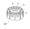
図24は、アウター9スロットのモータコアの外観を示す斜視図であるが、該モータコア900は、図25(a)に示すような平面形状のモータコア用薄板90が複数枚積重されてなるものである。モータコア用薄板90には、各ティース部91の基端付近に、パンチにより下面側に凸、上面側に凹の凹凸92が形成されており、該凹凸92を互いに嵌合させることにより、複数のモータコア用薄板90が積重されている。
【0003】
前記凹凸92の形状は様々であり、例えば円柱状の凹凸や角型でV字形状の凹凸等がある。また、凹凸92を形成する位置は、モータコアのティース部又はその基端近傍が一般的であり、他の形状のモータコア、例えば図25(b)に示すようなインナー9スロットのモータコア用薄板90aでも同様に、各ティース部91aの基端近傍に凹凸92aが形成される。
【0004】
図26は、前記モータコア900を製造するための高速プレスの順送金型の工程配置図であり、順送型内カシメ金型の一般的な工法を示している。図に示すように、プレス工程はS1〜S13の全13工程からなる。以下、各工程を順次説明する。
【0005】
まず、帯状の薄板材800の上下端付近にパイロット穴80を夫々穿つ(S1)。該パイロット穴80は、パンチ等の位置決めの基準となるものであり、該パイロット穴80を基準に薄板材800が送られる。なお、図においては薄板材800は右方向に順次送られるものとなっている。パイロット穴80を穿った後は、遊びスペースである(S2)。遊びスペースは、上型や下型等の部品の配置の関係、金型の抜き荷重の関係から、工程中の所要の箇所に配置される。
【0006】
次に、スロット穴81を打ち抜く(S3)。スロット穴81は、ティース部91の側縁を形成するためのものであり、アウター9スロットのモータコア900の場合は円環状に9つのスロット穴81が打ち抜かれる。スロット穴81を打ち抜いた後にも遊びスペースが配置される(S4)。
【0007】
次に、内径部82を打ち抜く(S5)。該内径部82は、後にモータコア900をモータとして組み立てる際に、ハウジング等と嵌合させるためのものである。該内径部82を打ち抜いた後にも遊びスペースが配置される(S6)。
【0008】
ここで、モータコア用薄板90を1個のモータコア900として積重する所定枚数毎にカットパンチを行う(S7)。即ち、カットパンチは、1個のモータコア900に積重された全モータコア用薄板90の枚数に対して1回だけなされるものであり、カウンタ等でコントロールされている。前記カットパンチによって、スロット穴81間であって、ティース部91の基端近傍となる位置にカット穴83が打ち抜かれる。該カット穴83は後述する凹凸92と略同寸法の貫通孔である。なお、カットパンチの後にも遊びスペースが配置される(S8)。
【0009】
次に、ベンドパンチを行う(S9)。ベンドパンチは、ティース部91の基端近傍となる位置に凹凸92を形成するためのものであり、薄板材800の板厚の60%前後となるようにパンチを出す。これにより、各ティース部91の基端近傍となる位置に、上面側に凹、下面側に凸の所謂半抜き成形の凹凸92が形成される。なお、前記カットパンチが行われている場合には、凹凸92が形成されるべき位置にカット穴83が形成されているので、凹凸92は形成されない。また、ベンドパンチの後にも遊びスペースが配置される(S10)。
【0010】
次に、外径部85を打ち抜くとともに、排圧を与えてモータコア用薄板90を排出する(S11)。これにより、モータコア用薄板90が薄板材800から打ち抜かれるとともに、排圧により既に打ち抜かれたモータコア用薄板90と圧接し、モータコア用薄板90の各凹凸92が、既に打ち抜かれたモータコア用薄板90の凹凸92と夫々嵌合して、モータコア用薄板90が型内で積重される。また、所定枚数のモータコア用薄板90が積重される毎に、前記カットパンチ(S7)によりカット穴83が形成され、凹凸92を有しないモータコア用薄板90が介在することにより、該カット穴83が形成されたモータコア用薄板90は、その後に打ち抜かれた凹凸92を有するモータコア用薄板90と嵌合しないので、所定枚数のモータコア用薄板90が積重されたモータコア900を型内に分離可能にストックすることができる。
【0011】
なお、外径部85が打ち抜かれた後の薄板材800は、遊びスペースが配置された後(S12)、適当な長さ毎にスクラップカットされる(S13)。このようにして、順送型内カシメ金型によりアウター9スロットのモータコア900が連続的に形成される。
【0012】
【発明が解決しようとする課題】
電気製品等の小型化に伴い、該製品に使用されるモータも小型化されているが、当然、該モータを構成するモータコアやそのティース部等も小型化される。しかし、前記モータコア用薄板90においてティース部91が小さくなると、該ティース部91の基端近傍に形成すべき凹凸92の寸法も小さくせざるを得ず、その結果、凹凸92同士の嵌合力が弱くなり、モータコア用薄板90を積重状態に維持するに必要な嵌合力が得られない。
【0013】
また、凹凸92の寸法を小さくするために金型を細くすれば、薄板材800に対するパンチの挫屈強度も小さくなる。従って、金型を用いたベンドパンチにより薄板材800に形成可能な凹凸92の最小寸法には限界がある。さらに、凹凸92の寸法を小さくすることにより不良率が増大する一方、金型の寿命が短くなる等の問題が発生し、モータコア900の工業生産が困難となるという問題もある。
【0014】
他方、モータコア900のティース部91に凹凸92を形成すること自体、モータコア900の磁路に抵抗をつくることとなり、モータ特性に悪影響を与えるという問題もある。
【0015】
本発明は、これらに鑑みてなされたものであり、薄板材を型抜き、積重してモータコアを製造する方法において、モータコア用薄板同士が嵌着して積重状態を維持することができ、小型のモータコアを容易に製造することが可能な製造方法を提供することを目的とする。
【0016】
また、本発明の他の目的は、モータコアの磁路に与える影響を少なくし、モータコア用薄板同士を嵌着させ、モータ特性を向上させることが可能な手段を提供することにある。
【0017】
本発明に係るモータコアの製造方法は、薄板材を所望の形状に型抜きして連続的にモータコア用薄板を形成するにあたり、モータコア用薄板の周縁部となる位置に、薄板材の表面から突出する所定幅の突出部分を形成するとともに、該突出部分が突出した側と反対側の面であって該突出部分と対応する位置に略同幅の凹陥部分とを形成した後、薄板材からモータコア用薄板を打ち抜くとともに、突出部分と凹陥部分とを嵌着させてモータコア用薄板を積重してモータコアとするモータコアの製造方法において、モータコア用薄板の周縁部のうち少なくとも突出部分および凹陥部分を形成すべき位置を含む一部を打ち抜いて半抜き用カット穴を穿設した後、半抜き用カット穴において半抜きを行って突出部分および凹陥部分を形成してから周縁部を形成するように薄板材からモータコア用薄板を打ち抜くものである。ここで、半抜きとは、所謂打抜きと同様のパンチを、モータコア用薄板の薄板材厚の数十パーセント程度をパンチの下死点として行うことにより、薄板材に凹凸を形成することをいう。このような半抜きにより突出部分および凹陥部分が形成されるが、半抜き後に薄板材からモータコア用薄板を打ち抜く際のパンチ力により、突出部分および凹陥部分が潰れたり断裂することがある。本発明では、薄板材からモータコア用薄板を打ち抜く際の力が先に形成した突出部分および凹陥部分に負荷されることを防止できる。
【0018】
ここでモータコアとは、ティース部が内方へ向いて円環状に配置されたインナースロットや外側へ向いて配置されたアウタースロットの他、巻線の占積率を向上させるためにティース部毎に分割された分割コア、ティース部が直線状に配置されたリニアモータ用コア等を含むものである。
【0021】
また、本発明は、薄板材との当接面に半抜き用カット穴と略同形状の凸部を有して上方向にバネ等により付勢されるとともに前記凸部がダイ表面から突出するような適当な位置を上限として上方向への移動が規制されているエジェクトピンの凸部を半抜き穴に嵌合するとともに当接面が薄板材の半抜き個所以外の部分に当接し、半抜きパンチ金型のパンチ面を半抜き個所と凸部とに当接させた状態で半抜きパンチを行うことにより、突出部分および凹陥部分を形成するものである。これにより、半抜きの際に薄板材が厚み方向に逃げることを防止して、確実に突出部分および凹陥部分を形成できる。
【0025】
【発明の実施の形態】
以下、本発明の実施の形態を図面に基づき具体的に説明する。
図1は、第1の実施の形態で製造されるモータコアの外観構成を示すものであるが、該モータコア100は、ティース部11が外方へ突出するように円環状に配置されてなるモータコア用薄板10が所定枚数積重されてなるものであり、該モータコア用薄板10のティース部11の外周縁部11aには、図2に示すように、断面が略尖形であって、その外側面12aが前記外周縁部11aの側面に沿って直立した所定幅の突出部分12と、突出部分12が突出した側と反対側の面の外周縁部11aであって該突出部分12と対応する位置に略同幅の凹陥部分13とが形成され、前記外周縁部11aの対応位置に形成された略同幅の突出部分12と凹陥部分13とが嵌着してモータコア用薄板10が積重されている。
【0026】
図3は、前記モータコア100を製造するための高速プレスの順送金型の工程配置図であり、順送型内カシメ金型の一般的な工法を示している。以下、各工程を順次説明する。
【0027】
帯状の薄板材200に、パイロット穴20、スロット穴21、及び内径部22を打ち抜く工程は、前述と同様の周知の工程である。即ち、薄板材200の上下端付近に位置決めの基準となるパイロット穴20を夫々穿った後(S101)、遊びスペースを介在させて(S102)、前記ティース部11の側縁を形成するスロット穴21を打ち抜き(S103)、さらに、内径部22を打ち抜く(S104)。
【0028】
内径部22を打ち抜いた後、モータコア用薄板10を1個のモータコア100として積重する所定枚数毎にカットパンチを行う(S105)。即ち、カットパンチは、1個のモータコア100に積重された全モータコア用薄板10の枚数に対して1回だけなされるものであり、カウンタ等でコントロールされている。
【0029】
図4は、カットパンチにより形成される切欠用カット穴23の詳細を説明するための図及び部分拡大図であるが、図に示すように、カットパンチによって、各ティース部11の外周面となる位置、即ちモータコア用薄板10の外径より内方の一部を打ち抜くように切欠用カット穴23が夫々穿たれる。該切欠用カット穴23の幅L1は、後の工程(S107)で形成される曲げ代用カット穴24aの幅(L4)と略同幅であり、ティース部11の幅L2の約1/4〜1/3程度とすることが好適である。
【0030】
一方、切欠用カット穴23を穿つ位置は、少なくともティース部11の外周面、即ちモータコア用薄板10の外径より薄板部材200の板厚L3分だけ内方となる部分を、切欠用カット穴23により抜き落とすものとする。勿論、切欠用カット穴23を、ティース部11の外周面から板厚L3以上内方の部分を抜き落とすこととしてもよいが、その後に形成される前記突出部分12と嵌着することを考慮すれば、切欠用カット穴23により外径より板厚L3だけ抜き落とすものことが好適である。これにより、各ティース部11の外周縁部11aであって、その後に形成される突出部分12と対応する位置に切欠部分14が夫々形成される。
【0031】
所定枚数毎にカットパンチ(S105)を行い、遊びスペースを介在させた後(S106)、カットパンチが行われていないものに対して、曲げ代部24を形成するための曲げ代用カット穴24aを打ち抜く(S107)。なお、カットパンチが行われた場合にも同様の工程が行われるが、カット穴23により曲げ代部24が形成されるべき外周縁部11aが抜き落とされているので、曲げ代部24が形成されることはない。
【0032】
図5は、曲げ代用カット穴24aの詳細を説明するための図及び部分拡大図であるが、図に示すように、各ティース部11の該外周縁部11aとなる位置より若干外方に曲げ代用カット穴24aが穿たれる。該曲げ代用カット穴24aの幅L4は、前記切欠用カット穴23の幅L1と略同幅である。一方、曲げ代用カット穴24aを穿つ位置は、ティース部11の外周面より薄板部材200の板厚L3分だけ外方となる部分を残して、即ち曲げ代部24を残して、それより外方を抜き落とすものとする。これにより、曲げ代部24の外周面が形成される。
【0033】
前記切欠用カット穴23及び曲げ代用カット穴24aは、薄板材200を型抜きして得るモータコア用薄板10の外径近傍から外方の位置に穿たれるものなので、その幅L1、L4はティース部11の幅L2以上とすることはできないものの、モータコア用薄板10の外径近傍から外方への寸法は、ティース部11の大きさ等の影響を受けない。従って、モータコアを小型化するに伴いティース部11等が小さくなったとしても、ティース部11の寸法に拘わらず曲げ代用カット穴24a及び切欠用カット穴23の大きさを一定以上とすることが可能である。
【0034】
また、前記幅L1、L4がティース部11の外周縁部11aの幅L2以内に制限されるとしても、切欠用カット穴23及び曲げ代用カット穴24aの大きさは、従来、ティース部11の基端付近に形成されていたディンプル等より十分に大きなものである。つまり、切欠用カット穴23及び曲げ代用カット穴24aを穿つためのパンチ寸法を、モータコアの寸法外で設定することができるので、モータコアを小型化してもパンチ寸法を金型製作が可能な程度とすることができる。従って、小型のモータコア用薄板10の作製が容易となり、金型の強度や寿命にも好影響を与える。
【0035】
前記曲げ代用カット穴24aを打ち抜いた後(S107)、曲げ代部24を潰す(S108)。
図6は、曲げ代部24の潰しを説明するための部分拡大図及び断面図であるが、図に示すように、各ティース部11の外周縁部11aとなる位置より外方部分、即ち曲げ代部24の断面形状が略穿形となるように潰す。このとき、潰し代L5は、曲げ代部24を曲折する際の湾曲R(図8)と略同寸法とすることが好適である。
【0036】
次に、曲げ代部24の両側から内方に向かって切込みを形成するとともに、次の曲げ工程(S110)のために、曲げ代部24を若干上方へ曲げる(S109)。
図7は、該切込み形成及び曲げを説明するための部分拡大図及び断面図であるが、図に示すように、曲げ代部24の両側からティース部11の方向へ切込みMが形成される。該切込みMは、ティース部11の外側面(モータコアの外径)より内方にまで至っており、ティース部11の外側面から薄板材200の板厚の約1.5倍程度まで切り込むことが好適である。該切込みMを形成することにより曲げ代部24の両側が形成される。さらに、該曲げ代部24を若干上方へ曲折する。これは、次の曲げ工程(S110)を容易とするためのものであり、図に示すように、薄板材200の表面に対する曲げ代部24の角度aが30°〜40°となるように曲折することが好適である。
【0037】
次に、曲げ代部24を直立するように曲げる(S110)。
図8は、該曲げ工程を説明するための部分拡大図及び断面図であるが、図に示すように、曲げ代部24が薄板材200の表面から上方へ突出するように曲折する。曲折された曲げ代部24は、ティース部11の外周縁部11aの側面に沿って直立しており、曲げによる湾曲Rは該側面より内方に形成されている。これにより、ティース部11の外周縁部11aに、突出部分12及び凹陥部分13が形成される。該突出部分12と凹陥部分の幅は同等であり、突出部分12の最大厚みは薄板材200の板厚L3と略同等であり、突出部分12の容積V1と凹陥部分13の容積V2とは略同等である。
【0038】
次に、遊びスペースを介在させた後(S111)、外径部25を打ち抜いて排圧を与える(S112)。これにより、薄板材200から図9に示すモータコア用薄板10が抜き出されるとともに、排圧により既に打ち抜かれたモータコア用薄板10と圧接し、図2に示すように、モータコア用薄板10の各突出部分12が、既に打ち抜かれたモータコア用薄板10の各凹陥部分13と夫々嵌着して、モータコア用薄板10が型内で積重される。なお、モータコア用薄板10同士を圧接させるための排圧は、周知の排圧リング等により付与することができる。
【0039】
一方、カットパンチ(S107)が行われた場合には、前述したように、曲げ代部24を形成すべき箇所が既に抜き落とされているので、前記突出部分12及び凹陥部分13は形成されない。図10はカットパンチが施されたモータコア用薄板10aの構成を示す平面図及び断面図であるが、図に示すように、各ティース部11の外周縁部11aには、カットパンチにより前記突出部分12と略同幅の切欠部分14が形成されている。該モータコア用薄板10aが積重すべき枚数毎に打ち抜かれることにより、薄板材200から連続してモータコア用薄板10が打ち抜き、且つ積重されてモータコア100が作製される場合に、各モータコア100の最上端に前記モータコア用薄板10aが積重されて、その後に打ち抜かれるモータコア用薄板10とは嵌着しないものとなる。また、モータコア用薄板10aが最上端に積重されることにより、モータコア100の端面等から突出部分12が突出せず、モータコア100をハウジング等と組み合わせることも容易となる。
【0040】
図11を用いてさらに詳細に説明するに、例えば、積重枚数をn枚とすると、図に示すように、(n−1)枚のモータコア用薄板10が順次打ち抜き、積重されて、各モータコア用薄板10においては、突出部分12と凹陥部分13とが嵌着している。n枚めは前記モータコア用薄板10aであり、該モータコア用薄板10aの切欠部分14と(n−1)枚めのモータコア用薄板10の突出部分12とが嵌着している。これにより、(n−1)枚のモータコア用薄板10と1枚のモータコア用薄板10aの計n枚が積重されて一つのモータコア100となる。
【0041】
一方、前記n枚めのモータコア用薄板10aは突出部分12を有しないので、(n+1)枚めのモータコア用薄板10の凹陥部分13とは嵌着せず、(n+1)枚めのモータコア用薄板10の突出部分12は、その後に打ち抜き、且つ積重された(n+2)枚めモータコア用薄板10の凹陥部分13と嵌着している。このように、n枚め毎に前記モータコア用薄板10aが打ち抜かれ、(n−1)枚のモータコア用薄板10が夫々嵌着して積重されたものの上端に嵌着して積重されることにより、連続して打ち抜き、且つ積重されたモータコア用薄板10がn枚毎に、即ちモータコア100毎に容易に分離可能となる。また、(n−1)枚めのモータコア用薄板10の突出部分12は、前記切欠部分14内に納まり、モータコア100の端面等から突出しない。
なお、図には示していないが、外径部25が打ち抜かれた後の薄板材200は、従来と同様に、適当な長さ毎にスクラップカットされる。
【0042】
本実施の形態ではアウター9スロットのモータコアを製造する場合について説明したが、インナースロットや分割コア等、その他の形状のモータコアについても本発明により製造可能であることは勿論である。また、モータコア用薄板10の積重方向は、打ち抜かれたモータコア用薄板10を上側へ順次積重するものとしても、下側へ積重するものとしてもよい。
【0043】
また、前記突出部分12及び凹陥部分13はティース部11の外周縁部11aの他に設けることも可能であるが、前記モータコア100がモータとして組み立てられる場合にハウジングと嵌合する部分等を考慮すれば、ティース部11の外周縁部11aに設けることが好適である。また、例えば、ティース部11の外周縁部11aと内径部との双方に前記突出部分12及び凹陥部分13を設けることにより、モータコア用薄板に作用する嵌着力が均一化されるので好ましい。また、レーザ溶接等、モータコア用薄板同士を積重するための他の固着手段を併用することも勿論可能である。
【0044】
以下、前記実施の形態に変形例に係るモータコア100bについて説明する。モータコア100bは、前記モータコア用薄板10の突出部分12及び凹陥部分13と断面形状が異なるものであり、その他の構成は前記モータコア100と同様であり、図において同じ符号は同一のものを示している。
【0045】
詳細には、図12に示すように、モータコア用薄板10bのティース部11の外周縁部11aに、断面が凸形の所定幅の突出部分12bと、該突出部分12bが突出した側と反対側の面の外周縁部11aであって該突出部分12bと対応する位置に略同幅の凹陥部分13bとが形成され、該突出部分12bと凹陥部分13bとが嵌着してモータコア用薄板10bが積重されてなるものである。
【0046】
図13は、前記モータコア100bを製造するための高速プレスの順送金型の工程配置図であるが、前記実施の形態において、曲げ代部24を形成して曲げを行う工程(図3、S107〜S110)に代えて半抜き工程(S113)とされている他は、前記実施の形態と同様の工程であり、以下の説明では、図3に示すS101〜S106、S111、S112の工程の詳細な説明は省略している。
【0047】
帯状の薄板材200に、スロット穴21(S103)、内径部22(S104)を形成した後、前述と同様に、モータコア100bとして積重する所定枚数毎に切欠用カット穴(S105)を形成する。次に、遊びスペースを介在させた後(S106)、カットパンチが行われていないものに対して、突出部分12b及び凹陥部分13bを形成するための半抜きパンチを行う(S113)。
【0048】
図14は、半抜きパンチの詳細を説明するための部分拡大図及び断面図であるが、図に示すように、前記カット穴23と同じ位置に、即ち各ティース部11の該外周縁部11aとなる位置より若干内方の位置から外方へ半抜きパンチを行う。該半抜きパンチは、薄板材200の板厚の60%前後となるようにパンチが出され、これにより、薄板材200の上面側に凹、下面側に凸の凹凸26が形成される。なお、前記カット穴23が形成されている場合には、凹凸26は形成されない。前記凹凸の幅L6は、前記切欠用カット穴23の幅L1と略同幅である。また、凹凸26は、ティース部11の外周面より薄板部材200の板厚L3分だけ内方となる位置まで形成されている。
【0049】
その後、前記実施の形態と同様に、遊びスペースを介在させた後(S111)、外径部25を打ち抜いて排圧を与える(S112)。これにより、薄板材200から図15に示すモータコア用薄板10bが抜き出されるとともに、排圧により既に打ち抜かれたモータコア用薄板10bと圧接し、図12に示すように、モータコア用薄板10bの各突出部分12bが、既に打ち抜かれたモータコア用薄板10bの各凹陥部分13bと夫々嵌着して、モータコア用薄板10bが型内で積重される。
【0050】
また、図12に示すように、カットパンチにより切欠部分14が形成されたモータコア用薄板10aが積重すべき枚数毎に打ち抜かれることにより、前述と同様に、連続して打ち抜き、積重されたモータコア用薄板10bがn枚毎に、即ちモータコア100b毎に容易に分離可能となる。
【0051】
このように、本変形例に係るモータコア100bにおいても、前記凹凸26を形成するための半抜きパンチは、薄板材200を型抜きして得るモータコア用薄板10bの外径近傍から外方の位置に穿たれるものなので、ティース部11の大きさ等の影響を受けない。従って、モータコアを小型化するに伴いティース部11等が小さくなったとしても、ティース部11の寸法に拘わらず半抜きパンチの大きさを一定以上とすることが可能である。これにより、小型のモータコア用薄板10bの作製が容易となり、金型の強度や寿命にも好影響を与える。
【0052】
以下、第2の実施の形態に係るモータコア300について説明する。
本モータコア300は、図16に示すように、ティース部31とヨーク部32とを具備してなる分割型のモータコアであり、所定数のモータコア300が円環状に連結されて所定スロットのモータコアをなすものである。該モータコア300は、ティース部31及びヨーク部32を形成するモータコア用薄板30が所定枚数積重されてなるものであり、該モータコア用薄板30のティース部31及びヨーク部32には、図17で示すように、所定幅の突出部分33と、該突出部分33が突出した側と反対側の面に、該突出部分33と対応する位置に略同幅の凹陥部分34とが形成され、該突出部分33と凹陥部分34とが嵌着してモータコア用薄板30が積重されている。
【0053】
前記突出部分33及び凹陥部分34は、モータコア300のティース部31及びヨーク部32の内側であって、後に巻線が巻回される芯部31a以外の部分の4ヶ所に形成されている。該突出部分33及び凹陥部分34を形成すべき位置は、パンチ寸法の大きさや、モータコアの磁路、モータ特性、ハウジングとの接合等を考慮して、モータコア用薄板30の周縁部の適当な位置に形成することができるが、突出部分33及び凹陥部分34による嵌着力がモータコア用薄板30に対して均等となるようにすることにより、モータコア用薄板30に反りや歪み等が生じ難いので好ましい。
【0054】
図18は、前記モータコア300を製造するための高速プレスの順送金型の工程配置図である。
帯状の薄板材200に、前述と同様に、パイロット穴20を形成した後(S201)、モータコア用薄板30を1個のモータコア300として積重する所定枚数毎にカットパンチを行う(S202)。なお、該カットパンチも、前記第1の実施の形態と同様に、1個のモータコア300に積重された全モータコア用薄板30の枚数に対して1回だけなされるように、カウンタ等でコントロールされている。
【0055】
図19は、カットパンチにより形成される切欠用カット穴27の詳細を説明するための拡大図であるが、図に示すように、前記カットパンチによって、周縁部29のうち、ティース部31及びヨーク部32の内側面となる位置より内方の一部を打ち抜くように切欠用カット穴27が夫々穿たれる。該切欠用カット穴27の幅L7は、後の工程(S204)で形成される突出部33及び凹陥部34の幅(L10)と略同幅である。
【0056】
一方、切欠用カット穴27を穿つ位置は、少なくともモータコア用薄板30の周縁部29より所定奥行L8だけ内方となる部分を、切欠用カット穴27により抜き落とすものとする。これにより、その後に形成される突出部分33と対応する位置に切欠部分35が夫々形成される。
【0057】
所定枚数毎にカットパンチ(S202)を行った後、半抜き用カット穴28を打ち抜く(S203)。図20は、半抜き用カット穴28の詳細を説明するための拡大図であるが、図に示すように、周縁部29のうち、ティース部31及びヨーク部32の内側面となる位置に半抜き用カット穴28が穿たれる。該半抜き用カット穴28の幅L9は、その後に形成される突出部33及び凹陥部34の幅(L10)より大きなものである。一方、半抜き用カット穴28を穿つ位置は、後述する半抜きパンチを行う位置を含むものである。従って、半抜き用カット穴28により、突出部分33及び凹陥部分34を形成すべき位置を含む周縁部29の一部分が形成される。
【0058】
前記半抜き用カット穴28を形成した後、半抜きパンチを行う(S204)。図21は、半抜きパンチの詳細を説明するための拡大図であるが、図に破線で示すように、前記切欠用カット穴27と同じ位置、即ち周縁部29のうち、ティース部31及びヨーク部32の内側の所定位置より若干内方で半抜きパンチを行う。該半抜きパンチは、薄板材200の板厚の70%前後となるようにパンチが出され、これにより、薄板材200の下面側に突出部33、上面側に凹陥部34が形成される。突出部33及び凹陥部34の幅L10及び周縁部29からの奥行L11は、前記切欠用カット穴27の幅L7及び奥行L8と夫々略同等である。従って、前記カット穴28が形成されている場合には、突出部33及び凹陥部34は形成されない。
【0059】
図22及び図23は、前記半抜きパンチの詳細を示す断面図である。図22(a)に示すように、ダイ40上に、順送される薄板材200が配置されており、その上方には半抜きパンチ用金型41が配置されている。一方、半抜きパンチを行う位置のダイ40にはエジェクトピン42が配設されている。該エジェクトピン42は、ダイ40に設けられた孔内に上下方向(パンチ方向)にスライド可能に配置されており、その上部には、前記半抜き用カット穴28と略同形状であって、薄板材200の厚みと略同等の出代の凸部42aを有している。また、エジェクトピン42はバネ等により上方向へ付勢されるとともに、前記凸部42aがダイ40表面から突出するような適当な位置を上限として、上方向への移動が規制されている。従って、エジェクトピン42は、上方からの押圧力により、図22(a)に示す位置から下方へスライド可能であり、該押圧力から開放されることにより、図に示す位置へ戻るものとなっている。
【0060】
半抜きパンチを行う際には、まず、図22(b)に示すように、半抜きパンチ用金型41が下降して薄板材200を押し下げ、これにより、エジェクトピン42の凸部42aが、半抜き用カット穴28に嵌合される。さらに、図23(a)に示すように、半抜きパンチ用金型41は、ダイ40の表面から薄板材200の板厚の約70%まで下降する。このとき、エジェクトピン42は、凸部42aが半抜き用カット穴28と嵌合した状態でパンチ用金型41に押されて下降する。一方、突出部33及び凹陥部34を形成すべき薄板材200の所定位置には、半抜きパンチが行われるが、この際、半抜き用カット穴28に嵌合したエジェクトピン42の凸部42aは、突出部33及び凹陥部34を形成すべき位置の薄板材200が、半抜きパンチ用金型41に押されて横方向へ逃げることを防止する。これにより、所望の突出部33及び凹陥部34が正確に形成される。その後、図23(b)に示すように、半抜き用金型41が上昇して、エジェクトピン42が薄板材200から離脱し、半抜きパンチが完了する。
【0061】
その後、図18に示すように、遊びスペースを介在させた後(S205)、モータコア用薄板30の周縁部29を打ち抜いて排圧を与える(S206)。これにより、薄板材200からモータコア用薄板30が抜き出されるとともに、排圧により既に打ち抜かれたモータコア用薄板30と圧接し、図17に示すように、モータコア用薄板30の各突出部分33が、既に打ち抜かれたモータコア用薄板30の各凹陥部分34と夫々嵌着して、モータコア用薄板30が型内で積重される。また、カットパンチにより切欠部分35が形成されたモータコア用薄板30が積重すべき枚数毎に打ち抜かれることにより、前述と同様に、連続して打ち抜き、積重されたモータコア用薄板30がn枚毎に、即ちモータコア300毎に容易に分離可能となる。
【0062】
このように、本実施の形態に係るモータコア300においても、半抜きパンチは、薄板材200を型抜きして得るモータコア用薄板30の外径近傍から外方の位置に穿たれるものなので、ティース部31の大きさ等の影響を受けない。従って、モータコアを小型化するに伴いティース部31等が小さくなったとしても、ティース部31の寸法に拘わらず半抜きパンチの大きさを一定以上とすることが可能である。これにより、小型のモータコア用薄板30の作製が容易となり、金型の強度や寿命にも好影響を与える。
【0063】
また、モータコア用薄板30の周縁部29のうち、前記突出部分33及び凹陥部分34を形成すべき位置を含む一部分を打ち抜いて予め周縁部29の一部を形成した後、半抜き用カット穴28内において半抜きパンチを行うこととしたので、最終的にモータコア用薄板30の周縁部29を打ち抜く際のパンチ力が、半抜きされた突出部分33及び凹陥部分34に加わることを防止して、周縁部29の打ち抜き加工を容易とすることができる。
【0064】
さらには、半抜きパンチを行う際に、エジェクトピン42を嵌合させて薄板材200が横方向へ逃げることを防止しているので、前記突出部分33及び凹陥部分34が正確に形成される。従って、モータコア用薄板30が積重されたモータコア300の側面に突出部分33及び凹陥部分34による凹凸等が生じることがなく、突出部分33及び凹陥部分34によるモータ特性等への影響が少なくなるという利点がある。
【0065】
なお、前記切欠用カット穴27及び半抜き用カット穴28は、ティース部31及びヨーク部32に夫々2つ、計4つ穿設することとしたが、ティース部31の芯部31aに対して同じ側に形成する切欠用カット穴27又は半抜き用カット穴28の一対を一体として穿設することも可能である。この場合、カットパンチの刃合わせが容易となり、金型の強度や寿命をより向上できるという利点がある。
【0066】
また、本実施の形態で示した工程は一例であり、例えば、モータコア300にオス/メスの合わせ目や、溶接代、通しボルト用の孔等を形成するための工程を適宜加えることは勿論可能である。
【0067】
【発明の効果】
以上説明したように、本発明に係るモータコアの製造方法によれば、薄板材のうちモータコア用薄板の周縁部となる部分の少なくとも突出部分および凹陥部分を形成すべき位置を含む部分をまず打ち抜いて半抜き用カット穴を穿った後で、この半抜き用カット穴において半抜きを行って突出部分および凹陥部分を形成してから薄板材からモータコア用薄板を打ち抜くので、薄板材からモータコア用薄板を打ち抜く際のパンチ力が、突出部分および凹陥部分に負荷されることを防止でき、モータコアの周縁部の打ち抜き加工が容易となる。
【0070】
また、本発明に係るモータコアによれば、薄板材との当接面に半抜き用カット穴と略同形状の凸部を有して上方向にバネ等により付勢されるとともに凸部がダイ表面から突出するような適当な位置を上限として上方向への移動が規制されているエジェクトピンの凸部を半抜き穴に嵌合するとともに、エジェクトピンの当接面が薄板材の半抜き個所以外の部分に当接し、かつ、半抜きパンチ金型のパンチ面が半抜き個所とエジェクトピンの凸部とに当接した状態で半抜きパンチを行うことにより突出部分および凹陥部分を形成するようにしたので、半抜きの際に薄板材が厚み方向へ逃げることを防止して、確実に突出部分および凹陥部分が形成でき、モータ特性等への影響を少なくすることができる。
【図面の簡単な説明】
【図1】本発明の実施の形態に係るモータコア100の構成を示す概略斜視図である。
【図2】図1のI−I断面を示す部分断面図である。
【図3】モータコア100を製造するための工程配置図である。
【図4】 (a)は、カットパンチ(S105)を説明するための図であり、(b)は、(a)の部分拡大図である。
【図5】 (a)は、曲げ代用カット穴24aの形成(S107)を説明するための図であり、(b)は、(a)の部分拡大図である。
【図6】 (a)は、曲げ代部24の潰し(S108)を説明するための部分拡大図であり、(b)は、(a)のII−II断面を示す部分断面図である。
【図7】 (a)は、切込みMの形成(S109)を説明するための部分拡大図であり、(b)は、(a)のIII−III断面を示す部分断面図である。
【図8】 (a)は、曲げ工程(S110)を説明するための部分拡大図であり、(b)は、(a)のIV−IV断面を示す部分断面図である。
【図9】 (a)は、モータコア用薄板10の構成を示す平面図であり、(b)は、(a)のV−V断面を示す部分断面図である。
【図10】 (a)は、モータコア用薄板10aの構成を示す平面図であり、(b)は、(a)のVI−VI断面を示す部分断面図である。
【図11】モータコア用薄板10aが介在したモータコア用薄板10の積重状態を示すティース部11の外周縁部11a付近の部分断面図である。
【図12】本発明の変形例に係るモータコア100bの要部構成を示す拡大断面図である。
【図13】モータコア100bを製造するための工程配置図である。
【図14】 (a)は、凹凸26の形成(S113)を説明するための部分拡大図であり、(b)は、(a)のVII−VII断面を示す部分断面図である。
【図15】 (a)は、モータコア用薄板10bの構成を示す平面図であり、(b)は、(a)のVIII−VIII断面を示す部分断面図である。
【図16】本発明の第2の実施の形態に係るモータコア300の構成を示す概略斜視図である。
【図17】図16のIX−IX断面を示す拡大断面図である。
【図18】モータコア300を製造するための工程配置図である。
【図19】切欠用カットパンチ27の形成(S202)を説明するための拡大図である。
【図20】半抜き用カットパンチ28の形成(S203)を説明するための拡大図である。
【図21】半抜きパンチ(S204)を説明するための拡大図である。
【図22】図21のX−X断面における半抜きパンチの工程の詳細を説明するための断面図である。
【図23】図21のX−X断面における半抜きパンチの工程の詳細を説明するための断面図である。
【図24】従来のモータコア900の外観を示す概略斜視図である。
【図25】 (a)は、アウター9スロットのモータコア用薄板90の構成を示す平面図であり、(b)は、インナー9スロットのモータコア用薄板90aの構成を示す平面図である。
【図26】モータコア900を製造するための工程配置図である。
【符号の説明】
100、100b、300 モータコア
10、10a、10b、30 モータコア用薄板
11a 周縁部
12、12b、33 突出部分
13、13b、34 凹陥部分
14、35 切欠部分
24 曲げ代部
28 半抜き用カット穴
29 周縁部
41 エジェクトピン
41a 凸部[0001]
BACKGROUND OF THE INVENTION
The present invention relates to a method for manufacturing a motor core in which thin sheets for a motor core are punched from a thin plate material and stacked.
[0002]
[Prior art]
FIG. 24 is a perspective view showing the outer appearance of the outer 9-slot motor core. The
[0003]
The
[0004]
FIG. 26 is a process layout diagram of a progressive die for a high-speed press for manufacturing the
[0005]
First,
[0006]
Next, the
[0007]
Next, the
[0008]
Here, the cut punching is performed for every predetermined number of stacked motor core
[0009]
Next, bend punching is performed (S9). The bend punch is for forming the
[0010]
Next, the
[0011]
The
[0012]
[Problems to be solved by the invention]
Along with miniaturization of electric products and the like, motors used in the products have also been miniaturized. Naturally, motor cores, teeth portions, and the like constituting the motors are also miniaturized. However, when the
[0013]
Further, if the die is made thin in order to reduce the size of the
[0014]
On the other hand, the formation of the
[0015]
The present invention has been made in view of these, and in a method of manufacturing a motor core by die cutting and stacking thin plate materials, motor core thin plates can be fitted to each other to maintain a stacked state, It is an object of the present invention to provide a manufacturing method capable of easily manufacturing a small motor core.
[0016]
Another object of the present invention is to provide means capable of reducing the influence on the magnetic path of the motor core, fitting the motor core thin plates together, and improving the motor characteristics.
[0017]
The motor core manufacturing method according to the present invention projects from the surface of the thin plate material at a position that becomes the peripheral portion of the motor core thin plate when the thin plate material is die-cut into a desired shape to continuously form the thin plate for the motor core. A projecting portion having a predetermined width is formed, and a concave portion having substantially the same width is formed at a position corresponding to the projecting portion on the surface opposite to the projecting portion. In a manufacturing method of a motor core, in which a thin plate is punched and a protruding portion and a recessed portion are fitted to stack a thin plate for a motor core to form a motor core, at least a protruding portion and a recessed portion are formed among the peripheral portions of the thin plate for the motor core. After punching a part including the power position and drilling a cut hole for half-punching, half-punching is performed in the cut hole for half-punching to form a protruding part and a recessed part, and then the periphery In which punched motor core for thin from sheet metal to form. Here, half punching refers to forming irregularities on a thin plate material by performing a punch similar to so-called punching, with the bottom dead center of the punch being about several tens percent of the thickness of the thin plate of the motor core thin plate. Although the protruding portion and the recessed portion are formed by such half punching, the protruding portion and the recessed portion may be crushed or torn due to the punching force when punching out the motor core thin plate from the thin plate material after half punching. In this invention, it can prevent that the force at the time of punching out the thin plate for motor cores from a thin plate material is loaded on the protrusion part and recessed part which were formed previously.
[0018]
Here, the motor core is an inner slot arranged in an annular shape with the teeth portion facing inward and an outer slot arranged facing the outside, as well as for each tooth portion in order to improve the space factor of the winding. The divided core includes a divided core, a core for a linear motor in which teeth are arranged linearly, and the like.
[0021]
Further, according to the present invention, a convex portion having substantially the same shape as the semi-cut-out cut hole is provided on the contact surface with the thin plate material, and the convex portion protrudes from the die surface while being biased upward by a spring or the like. The protrusion of the eject pin, which is controlled to move upward with an appropriate position as the upper limit, is fitted into the half punching hole, and the contact surface is in contact with a portion other than the half punching portion of the thin plate material. The projecting portion and the recessed portion are formed by performing the half punching with the punch surface of the punching punch mold in contact with the half punching portion and the convex portion. Thereby, it is possible to prevent the thin plate material from escaping in the thickness direction during half-punching and to reliably form the protruding portion and the recessed portion.
[0025]
DETAILED DESCRIPTION OF THE INVENTION
Hereinafter, embodiments of the present invention will be described in detail with reference to the drawings.
FIG. 1 shows an external configuration of the motor core manufactured in the first embodiment. The
[0026]
FIG. 3 is a process layout diagram of a progressive die for a high-speed press for manufacturing the
[0027]
The process of punching the
[0028]
After punching out the
[0029]
FIG. 4 is a diagram and a partially enlarged view for explaining details of the
[0030]
On the other hand, at least the outer peripheral surface of the
[0031]
After performing a cut punch (S105) for every predetermined number of sheets and interposing a play space (S106), a bending substitute cut
[0032]
FIG. 5 is a diagram and a partially enlarged view for explaining the details of the bending substitute cut
[0033]
Since the
[0034]
Further, even if the widths L1 and L4 are limited to be within the width L2 of the outer
[0035]
After punching the bending substitute cut
FIG. 6 is a partially enlarged view and a cross-sectional view for explaining the crushing of the bending
[0036]
Next, incisions are formed inward from both sides of the bending
FIG. 7 is a partially enlarged view and a cross-sectional view for explaining the incision formation and bending. As shown in the drawing, the incisions M are formed from both sides of the bending
[0037]
Next, the bending
FIG. 8 is a partially enlarged view and a cross-sectional view for explaining the bending process. As shown in the drawing, the bending
[0038]
Next, after a play space is interposed (S111), the
[0039]
On the other hand, when the cut punch (S107) is performed, the protruding
[0040]
To explain in more detail with reference to FIG. 11, for example, when the number of stacked sheets is n, as shown in the figure, (n-1) sheets of motor core
[0041]
On the other hand, since the nth motor core
Although not shown in the drawing, the
[0042]
In this embodiment, the case of manufacturing a motor core having an outer 9 slot has been described, but it is needless to say that motor cores having other shapes such as an inner slot and a split core can be manufactured by the present invention. Further, the stacking direction of the motor core
[0043]
Further, the protruding
[0044]
Hereinafter, a motor core 100b according to a modification of the above embodiment will be described. The motor core 100b has a different cross-sectional shape from the protruding
[0045]
Specifically, as shown in FIG. 12, the outer
[0046]
FIG. 13 is a process layout diagram of a progressive die of a high-speed press for manufacturing the motor core 100b. In the embodiment, a process of forming a bending
[0047]
After the slot hole 21 (S103) and the inner diameter portion 22 (S104) are formed in the strip-shaped
[0048]
FIG. 14 is a partially enlarged view and a cross-sectional view for explaining the details of the half punch, but as shown in the drawing, at the same position as the
[0049]
Thereafter, similarly to the above-described embodiment, after a play space is interposed (S111), the
[0050]
Further, as shown in FIG. 12, the motor core
[0051]
As described above, also in the motor core 100b according to this modification, the half punching for forming the
[0052]
Hereinafter, the
As shown in FIG. 16, the
[0053]
The protruding
[0054]
FIG. 18 is a process layout diagram of a progressive die for a high-speed press for manufacturing the
After the pilot holes 20 are formed in the belt-shaped thin plate material 200 (S201) as described above, cut punching is performed for every predetermined number of sheets stacked with the motor core
[0055]
FIG. 19 is an enlarged view for explaining details of the notch cut
[0056]
On the other hand, at least a portion that is inward by a predetermined depth L8 from the
[0057]
After performing the cut punch (S202) for every predetermined number of sheets, the half-
[0058]
After forming the half-
[0059]
22 and 23 are cross-sectional views showing details of the half punching punch. As shown in FIG. 22 (a), a progressively fed
[0060]
When performing the half punching, first, as shown in FIG. 22 (b), the half punching die 41 is lowered to push down the
[0061]
Then, as shown in FIG. 18, after a play space is interposed (S205), the
[0062]
Thus, also in the
[0063]
In addition, a part of the
[0064]
Further, when the half punching is performed, the
[0065]
The
[0066]
In addition, the process shown in the present embodiment is an example. For example, a process for forming a male / female joint, a welding allowance, a hole for a through bolt, and the like can be appropriately added to the
[0067]
【The invention's effect】
As described above, according to the method for manufacturing a motor core according to the present invention, at least a portion including a position where a protruding portion and a recessed portion are to be formed is first punched out of a thin plate material which is a peripheral portion of a thin plate for a motor core. After drilling a half-cut hole, the motor core thin plate is punched out of the thin plate material by punching out the motor core thin plate from the thin plate material after half-cutting in the cut hole for half punching to form the protruding portion and the recessed portion. The punching force at the time of punching can be prevented from being applied to the protruding portion and the recessed portion, and the peripheral edge of the motor core can be easily punched.
[0070]
Further, according to the motor core of the present invention, the convex portion having the same shape as the half-cut hole is formed on the contact surface with the thin plate material, and the convex portion is urged upward by a spring or the like. Fit the convex part of the eject pin, which is restricted from moving upward with an appropriate position protruding from the surface, into the half punch hole, and the eject pin contact surface is the half punch part of the thin plate material The projecting part and the recessed part are formed by carrying out the half punching in a state where the punch surface of the half punching die is in contact with the half punching part and the convex part of the eject pin. Therefore, it is possible to prevent the thin plate material from escaping in the thickness direction at the time of half punching, and to reliably form the protruding portion and the recessed portion, thereby reducing the influence on the motor characteristics and the like.
[Brief description of the drawings]
FIG. 1 is a schematic perspective view showing a configuration of a
2 is a partial cross-sectional view showing a cross section taken along the line II of FIG.
3 is a process layout diagram for manufacturing the
4A is a view for explaining a cut punch (S105), and FIG. 4B is a partially enlarged view of FIG. 4A.
5A is a view for explaining the formation of a bending substitute cut
6A is a partially enlarged view for explaining crushing of a bending margin 24 (S108), and FIG. 6B is a partial sectional view showing a II-II section of FIG.
7A is a partially enlarged view for explaining the formation of the cut M (S109), and FIG. 7B is a partial cross-sectional view showing a III-III cross section of FIG.
8A is a partially enlarged view for explaining a bending step (S110), and FIG. 8B is a partial cross-sectional view showing a IV-IV section of FIG. 8A.
9A is a plan view showing the configuration of the motor core
10A is a plan view showing a configuration of a motor core
11 is a partial cross-sectional view of the vicinity of an outer
FIG. 12 is an enlarged cross-sectional view showing the main configuration of a motor core 100b according to a modification of the present invention.
FIG. 13 is a process layout diagram for manufacturing the motor core 100b.
14A is a partially enlarged view for explaining the formation of irregularities 26 (S113), and FIG. 14B is a partial sectional view showing a VII-VII cross section of FIG. 14A.
15A is a plan view showing a configuration of a motor core
FIG. 16 is a schematic perspective view showing a configuration of a
17 is an enlarged cross-sectional view showing a cross section IX-IX in FIG. 16;
18 is a process layout diagram for manufacturing the
FIG. 19 is an enlarged view for explaining the formation (S202) of the
20 is an enlarged view for explaining the formation (S203) of the half punch cut
FIG. 21 is an enlarged view for explaining a half punch (S204).
22 is a cross-sectional view for explaining details of the half punching process in the XX cross section of FIG. 21. FIG.
FIG. 23 is a cross-sectional view for explaining details of the half punching process in the XX cross section of FIG. 21;
24 is a schematic perspective view showing the appearance of a
FIG. 25A is a plan view showing a configuration of a motor core
26 is a process layout diagram for manufacturing the
[Explanation of symbols]
100, 100b, 300 Motor core
10, 10a, 10b, 30 Motor core thin plate
11a peripheral edge
12, 12b, 33 Projecting part
13, 13b, 34 Recessed part
14, 35 Notch
24 Bending allowance
28 Cut hole for half punching
29 Edge
41 Eject pin
41a Convex
Claims (2)
前記モータコア用薄板の前記周縁部のうち少なくとも前記突出部分および前記凹陥部分を形成すべき位置を含む一部を打ち抜いて半抜き用カット穴を穿設した後、該半抜き用カット穴において半抜きを行って前記突出部分および前記凹陥部分を形成してから前記周縁部を形成するように前記薄板材から前記モータコア用薄板を打ち抜くことを特徴とする、モータコアの製造方法。 After punching at least a part of the peripheral portion of the motor core thin plate including a position where the protruding portion and the recessed portion are to be formed to form a half-cut hole, the half-cut hole is half-cut. The motor core manufacturing method is characterized in that the motor core thin plate is punched from the thin plate material so as to form the projecting portion and the recessed portion and then forming the peripheral portion.
Priority Applications (1)
| Application Number | Priority Date | Filing Date | Title |
|---|---|---|---|
| JP2002223194A JP3777435B2 (en) | 2002-04-08 | 2002-07-31 | Manufacturing method of motor core and motor core |
Applications Claiming Priority (2)
| Application Number | Priority Date | Filing Date | Title |
|---|---|---|---|
| JP2002104960 | 2002-04-08 | ||
| JP2002223194A JP3777435B2 (en) | 2002-04-08 | 2002-07-31 | Manufacturing method of motor core and motor core |
Publications (2)
| Publication Number | Publication Date |
|---|---|
| JP2004007936A JP2004007936A (en) | 2004-01-08 |
| JP3777435B2 true JP3777435B2 (en) | 2006-05-24 |
Family
ID=30446735
Family Applications (1)
| Application Number | Title | Priority Date | Filing Date |
|---|---|---|---|
| JP2002223194A Expired - Fee Related JP3777435B2 (en) | 2002-04-08 | 2002-07-31 | Manufacturing method of motor core and motor core |
Country Status (1)
| Country | Link |
|---|---|
| JP (1) | JP3777435B2 (en) |
Cited By (1)
| Publication number | Priority date | Publication date | Assignee | Title |
|---|---|---|---|---|
| CN103958088A (en) * | 2011-11-22 | 2014-07-30 | 株式会社三井高科技 | Processing device and processing method |
Families Citing this family (7)
| Publication number | Priority date | Publication date | Assignee | Title |
|---|---|---|---|---|
| JP4654012B2 (en) * | 2004-12-02 | 2011-03-16 | 株式会社三井ハイテック | Manufacturing method of laminated iron core |
| JP4648716B2 (en) * | 2005-02-03 | 2011-03-09 | 株式会社ニッセイ | Laminated iron core and manufacturing method thereof |
| JP4834433B2 (en) | 2006-03-15 | 2011-12-14 | 株式会社富士通ゼネラル | Manufacturing method of stator core for axial air gap type motor |
| JP2012156816A (en) * | 2011-01-26 | 2012-08-16 | Toshiba Corp | Image display apparatus and image display method |
| KR101730739B1 (en) * | 2015-11-30 | 2017-04-27 | 나라엠앤디(주) | Method for manufacturing inner core of linear motor using progerssive mold |
| KR101730738B1 (en) | 2015-11-30 | 2017-04-27 | 나라엠앤디(주) | Progressive molding apparatus for manufacturing inner core of linear motor |
| CN113949235B (en) * | 2021-12-21 | 2022-02-22 | 宁波震裕科技股份有限公司 | Manufacturing process of motor rotor iron core with special-shaped tooth part |
-
2002
- 2002-07-31 JP JP2002223194A patent/JP3777435B2/en not_active Expired - Fee Related
Cited By (4)
| Publication number | Priority date | Publication date | Assignee | Title |
|---|---|---|---|---|
| CN103958088A (en) * | 2011-11-22 | 2014-07-30 | 株式会社三井高科技 | Processing device and processing method |
| CN103958088B (en) * | 2011-11-22 | 2016-03-16 | 株式会社三井高科技 | Processing unit (plant) and processing method |
| US10058908B2 (en) | 2011-11-22 | 2018-08-28 | Mitsui High-Tec, Inc. | Processing device and processing method |
| US10981211B2 (en) | 2011-11-22 | 2021-04-20 | Mitsui High-Tec, Inc. | Processing device and processing method |
Also Published As
| Publication number | Publication date |
|---|---|
| JP2004007936A (en) | 2004-01-08 |
Similar Documents
| Publication | Publication Date | Title |
|---|---|---|
| US4728842A (en) | Laminated assembly for a dynamoelectric machine and method for manufacturing laminated assemblies having ridges formed on projections which interlock with recesses of adjacent laminations | |
| JP5053990B2 (en) | Laminate made of sheet metal and process for forming sheet laminate | |
| WO2002097948A1 (en) | Laminated core and method of producing laminated core | |
| JP3777435B2 (en) | Manufacturing method of motor core and motor core | |
| CN102082470A (en) | Laminated stator core | |
| JP2017147814A (en) | Manufacturing method of laminated core, and manufacturing apparatus of laminated core | |
| EP0441046A1 (en) | Method for stamping stepper motor laminations | |
| JP3954595B2 (en) | Method for manufacturing laminated iron core and mold apparatus | |
| JP3989510B2 (en) | Laminated iron core and method for manufacturing the same | |
| JP3710706B2 (en) | Manufacturing method of laminated core and mold apparatus used for manufacturing the same | |
| US4809429A (en) | Apparatus for manufacturing laminated assemblies having ridges formed on projections which interlock with recesses of adjacent laminations | |
| US6877214B2 (en) | Method of manufacturing a stack of laminations | |
| JP3776052B2 (en) | Laminated iron core | |
| JP2007282498A (en) | Laminated core and its method of manufacturing | |
| CN113275459A (en) | Manufacturing process of step type iron core | |
| JP3400437B2 (en) | Side curved type laminated core and method of manufacturing the same | |
| EP0951079A1 (en) | Dry cell and method of manufacturing outer can therefor | |
| KR20050045711A (en) | Progressive stamping die apparatus and method for manufacturing stack of laminae | |
| JP4722970B2 (en) | Manufacturing method of laminated iron core | |
| JP4484616B2 (en) | Manufacturing method of laminated iron core | |
| JP3842146B2 (en) | Manufacturing method of laminated iron core | |
| JP2008253135A (en) | Laminated core | |
| KR20000016947A (en) | Thin Metal Plate Stack Assembly and Method of Making the same | |
| JP2001121227A (en) | Laminated binding part | |
| JP4375981B2 (en) | Manufacturing method and manufacturing apparatus of iron core for cylindrical coil |
Legal Events
| Date | Code | Title | Description |
|---|---|---|---|
| A621 | Written request for application examination |
Free format text: JAPANESE INTERMEDIATE CODE: A621 Effective date: 20050301 |
|
| A977 | Report on retrieval |
Free format text: JAPANESE INTERMEDIATE CODE: A971007 Effective date: 20050824 |
|
| A131 | Notification of reasons for refusal |
Free format text: JAPANESE INTERMEDIATE CODE: A131 Effective date: 20050922 |
|
| A521 | Written amendment |
Free format text: JAPANESE INTERMEDIATE CODE: A523 Effective date: 20051109 |
|
| TRDD | Decision of grant or rejection written | ||
| A01 | Written decision to grant a patent or to grant a registration (utility model) |
Free format text: JAPANESE INTERMEDIATE CODE: A01 Effective date: 20060105 |
|
| A61 | First payment of annual fees (during grant procedure) |
Free format text: JAPANESE INTERMEDIATE CODE: A61 Effective date: 20060203 |
|
| R150 | Certificate of patent or registration of utility model |
Free format text: JAPANESE INTERMEDIATE CODE: R150 |
|
| FPAY | Renewal fee payment (event date is renewal date of database) |
Free format text: PAYMENT UNTIL: 20120310 Year of fee payment: 6 |
|
| FPAY | Renewal fee payment (event date is renewal date of database) |
Free format text: PAYMENT UNTIL: 20130310 Year of fee payment: 7 |
|
| FPAY | Renewal fee payment (event date is renewal date of database) |
Free format text: PAYMENT UNTIL: 20140310 Year of fee payment: 8 |
|
| R250 | Receipt of annual fees |
Free format text: JAPANESE INTERMEDIATE CODE: R250 |
|
| R250 | Receipt of annual fees |
Free format text: JAPANESE INTERMEDIATE CODE: R250 |
|
| LAPS | Cancellation because of no payment of annual fees |