JP4648716B2 - Laminated iron core and manufacturing method thereof - Google Patents
Laminated iron core and manufacturing method thereof Download PDFInfo
- Publication number
- JP4648716B2 JP4648716B2 JP2005027186A JP2005027186A JP4648716B2 JP 4648716 B2 JP4648716 B2 JP 4648716B2 JP 2005027186 A JP2005027186 A JP 2005027186A JP 2005027186 A JP2005027186 A JP 2005027186A JP 4648716 B2 JP4648716 B2 JP 4648716B2
- Authority
- JP
- Japan
- Prior art keywords
- caulking
- iron core
- laminated
- diameter side
- skew
- Prior art date
- Legal status (The legal status is an assumption and is not a legal conclusion. Google has not performed a legal analysis and makes no representation as to the accuracy of the status listed.)
- Active
Links
Images


Description
本発明は、電動機用の固定子又は回転子に用いる積層鉄心とその製造方法に係り、特に順送り金型装置によって整列積み(垂直積層)した各鉄心板をかしめ結合手段によって相互に仮固着すると共に、順送り金型装置から取り出して巻線を施した後に所望角度のスキュー回転を付与することが可能な積層鉄心とその製造方法に関する。 The present invention relates to a laminated core used for a stator or rotor for an electric motor and a method for manufacturing the same, and in particular, each iron core plate aligned and stacked (vertically laminated) by a progressive die apparatus is temporarily fixed to each other by caulking and coupling means. The present invention relates to a laminated iron core capable of giving a skew rotation of a desired angle after being taken out from a progressive die apparatus and subjected to winding, and a manufacturing method thereof.
電動機用の積層鉄心では、積層する各鉄心板の板厚偏差による積み厚のバラツキなどを是正するために回し積みを行ったり、ゴギングによるトルク変動や騒音の発生などを低減するためにスキュー回転を付与しており、回し積みは順送り金型装置によって積層時に行われるが、特にスキュー回転を付与するための方法としては、順送り金型装置によって積層時に行う場合と、整列積みした積層鉄心を順送り金型装置から取出した後に行う場合とがある。 For laminated cores for electric motors, the stacking is performed to correct variations in stacking thickness due to deviations in the thickness of each laminated core, and skew rotation is used to reduce torque fluctuation and noise due to gogging. The stacking is performed at the time of stacking by the progressive die device, and in particular, as a method for imparting the skew rotation, the stacking iron cores that are aligned and stacked are forwarded at the time of stacking by the progressive die device. Sometimes after removing from the mold device.
スキュー回転の付与を順送り金型装置によって積層時に行う場合には、順送り金型装置内にスキュー回転させる回転機構を設ける必要があり、特に回し積みを行う場合には両者を兼ね備えた割り出し機構が必要であるから、金型装置の構造や制御を複雑にしたり、作業能率を低下させる恐れがあると共に、各鉄心板のスロット部が不整合状態になるので、スロット部に対して巻線を施したり、予め巻線したコイルアッセンブリを装着する作業を容易且つ能率的に行うことができない。 When skew rotation is applied at the time of stacking using a progressive mold apparatus, it is necessary to provide a rotation mechanism that rotates the skew in the progressive mold apparatus, and particularly when rotating and stacking, an indexing mechanism that combines both is necessary. Therefore, there is a risk that the structure and control of the mold apparatus may be complicated, the work efficiency may be reduced, and the slot portions of each iron core plate are in an inconsistent state. The work of mounting the pre-wound coil assembly cannot be easily and efficiently performed.
そこで、順送り金型装置によって積層時に各鉄心板のスロット部が整合状態となる整列積みを行い、この整列積みされた積層鉄心を順送り金型装置から取出し、スロット部に対して自動巻線機で巻線を施すかコイルアッセンブリを装着した後に、専用の治工具などを用いてスキュー回転を付与するようにする方法を採り、これによって積層鉄心に対する巻線を容易に行って作業能率の向上を図るようにした先行技術が、例えば特許文献1〜10などで提案されている。
Therefore, the stacked mold cores are aligned and stacked so that the slot portions of each iron core plate are aligned during stacking, and the stacked stacked cores are taken out from the progressive mold device, and the slot portions are automatically wound by an automatic winding machine. After applying the winding or mounting the coil assembly, a method of applying skew rotation using a special tool or the like is adopted, and this facilitates winding to the laminated iron core to improve work efficiency. Such prior arts have been proposed in, for example,
これらの先行技術には、各鉄心板の相互間を連結しない状態で、スキュー用の工具内に積層してスキュー回転させるもの(特許文献1)、円周方向に順次変位するV字状の凹部と凸部を形成した各鉄心板を仮組立状態で積層し、これを軸方向から圧縮してスキュー回転させるもの(特許文献2)、仮止め部材を外周溝に装着して各鉄心板を仮止めした後に、仮止め部材を取り外して外周溝又はスロットなどに棒状の捻り部材を装着してスキュー回転させるもの(特許文献3,4,5)がある。
In these prior arts, the iron core plates are not connected to each other and stacked in a skew tool and rotated by skew (Patent Document 1), a V-shaped concave portion that is sequentially displaced in the circumferential direction. And the core plates formed with the convex portions are laminated in a temporarily assembled state, and this is compressed from the axial direction to rotate the skew (Patent Document 2). After stopping, there is a device (
また、内周面に凹溝を設けた各鉄心板の相互間をV溝状の突起で半かしめ状態に連結して整列積みし、内周面に軸線方向に傾斜する突起状の係止具を備えた型枠に対して、凹溝を係止具に嵌合させた状態で上面から押圧すると、係止具に沿ってスキュー回転しながら突起がかしめ結合するもの(特許文献6)、突起と突起が遊嵌する長孔を有する各鉄心板を整列積みし、積層鉄心を一方向へ回転させた際に突起が長孔内を移動してスキュー回転するもの(特許文献7)がある。 In addition, the iron core plates having concave grooves on the inner peripheral surface are connected in a semi-caulked state with V-groove protrusions and aligned and stacked, and the protrusion-shaped locking tool is inclined in the axial direction on the inner peripheral surface. When the groove is pressed from the upper surface in a state where the groove is fitted to the locking tool, the protrusion is caulked and coupled while being rotated along the locking tool (Patent Document 6). And the iron core plates having long holes in which the protrusions are loosely fitted are aligned and stacked, and when the laminated core is rotated in one direction, the protrusions move in the long holes and rotate skew (Patent Document 7).
さらに、各鉄心板に対して同一半径の異なる位置にかしめ突起(突起)とかしめ孔(開口又は受け入れ領域)を設け、上下に隣接する一方鉄心板のかしめ突起が他方鉄心板のかしめ孔に嵌合できる状態で整列積みすると共に、かしめ孔を円周方向に長く形成してかしめ突起を嵌合した際に回転可能な隙間が形成されるようにし、かしめ孔に対するかしめ突起の移動範囲内でスキュー回転できるようにするもの(特許文献8,9)がある。
Furthermore, caulking protrusions (protrusions) and caulking holes (openings or receiving areas) are provided at different positions on the same radius with respect to each iron core plate, and the caulking protrusions of one iron core plate adjacent to the upper and lower sides fit into the caulking holes in the other iron core plate. The caulking holes are formed long in the circumferential direction so that they can be joined together, so that a rotatable gap is formed when the caulking protrusions are fitted, and the caulking protrusions move within the range of movement relative to the caulking holes. There exists what enables it to rotate (
しかしながら、例えば特許文献1や特許文献3,4,5などの先行技術の場合には、自由にスキューを付与できる利点はあるが、各鉄心板を順送り金型装置で打抜き加工した後に、積層に必要な所定枚数分の各鉄心板を取り出し、前者の場合には各鉄心板を順次型枠に装着させ、後者の場合には仮止め部材を着脱させる煩雑な作業が必要であって、順送り金型装置から積層鉄心として必要な所定枚数分の各鉄心板を一括して取り出してスキューを付与する場合に比べ、作業能率良く大量生産するのには適していなかった。
However, in the case of the prior arts such as
また、特許文献2などの先行技術の場合には、各鉄心板は相互間を連結しない状態で、軸穴案内棒とスロット案内棒に支持されて仮組立されるので、特許文献1や特許文献3,4,5などの場合と同様に作業能率良く大量生産するのには適していないことに加え、各鉄心板に間隙を有する不安定な状態で巻線作業が行われること、V字状の凹部と凸部との嵌合を円周方向に変位させてスキューを付与するので、スキュー回転は一定角度に限定されること、などの課題があった。
Further, in the case of the prior art such as
また、特許文献6などの先行技術の場合には、各鉄心板の相互間をV溝状の突起で半かしめ状態に連結しているので、上記した特許文献1〜5などの課題を解決することが可能であるが、V溝状の突起によって各鉄心板は比較的強固に連結されているので、内周面の凹溝を型枠の係止具に嵌合させた状態で積層鉄心の上面を押圧しても、各鉄心板を円滑に回転させてスキューを付与することが困難であると共に、スキューの付与は一方向に限定されること、などの課題があった。
Further, in the case of the prior art such as
また、特許文献7などの先行技術の場合には、各鉄心板は長穴と突起とを整合させるために、順送り金型装置内において45度だけ相対回転した位置関係で、2種類の鉄心板を交互に打抜き加工し且つ積層する必要があるので、金型装置を複雑にし且つ作業能率を低下させる恐れがあること、整列積みした積層鉄心の各鉄心板は長穴と突起とが遊嵌状態であるから、金型装置から取り外す際や巻線作業時などに外力を受けるとスキュー方向にずれ易く巻線作業に支障を来たす恐れがあること、などの課題があった。
Further, in the case of the prior art such as
また、特許文献8などの先行技術の場合には、かしめ突起を設けた鉄心板とかしめ孔を設けた鉄心板の2種類を、順送り金型装置内で打抜き加工して交互に積層する必要があり、特許文献9では各鉄心板に対して別工程で打抜き加工した突起と開口又は受け入れ領域を、整合状態にして積層する必要があるので、特許文献7などと同様に金型装置を複雑にし且つ作業能率を低下させる恐れがあると共に、これらのかしめ突起(突起)とかしめ孔(開口又は受け入れ領域)の仮固着が強固な場合には、特許文献6などと同様に各鉄心板円滑にスキュー回転させることが困難であること、などの課題があった。
In the case of the prior art such as
そこで本発明では、これら従来技術の課題を解決し得る積層鉄心とその製造方法を提供するものであって、順送り金型装置によって整列積み(垂直積層)した各鉄心板をかしめ結合手段によって相互に仮固着すると共に、順送り金型装置から取り出して巻線を施した後に所望角度のスキュー回転を付与することを可能にし、特に各鉄心板を仮固着するかしめ結合手段を改善してスキュー回転を容易且つ確実にすると共に、各鉄心板を打抜き加工して整列積み(垂直積層)する順送り金型装置の構造及び工程を、簡単で且つ作業能率の良いものにすること、などを主たる目的としている。 Therefore, the present invention provides a laminated iron core and a method for manufacturing the same, which can solve these problems of the prior art, and each iron core plate that is aligned and stacked (vertically laminated) by a progressive die device is mutually connected by caulking and coupling means. In addition to temporary fixing, it is possible to apply a skew rotation at a desired angle after taking out from the progressive die device and winding it, and in particular, improving the caulking coupling means for temporarily fixing each iron core plate to facilitate skew rotation In addition, the main purpose is to make the structure and process of a progressive mold apparatus for punching and aligning (vertically laminating) each iron core plate simple and efficient in operation.
本発明による積層鉄心は、外周に係合部を設けた各鉄心板を整列積み状態で積層して連結すると共に、巻線後にスキュー回転可能なかしめ結合手段として、前記鉄心板の軸心を中心とする円弧状に形成されて円周方向に摺動回転可能なかしめ部と、かしめ部の一端又は両端にスキュー領域を確保する打抜き部を設け、かしめ部は半抜き状態に打抜き加工したかしめ凹部とかしめ凸部で形成し、上下に隣接する一方鉄心板のかしめ凸部が他方鉄心板のかしめ凹部に嵌合される積層鉄心であって、各鉄心板において、当該鉄心板の前記軸心から前記かしめ凸部の内径側までの距離が前記軸心から前記かしめ凹部の内径側までの距離より短く、かつ前記軸心から前記かしめ凸部の外径側までの距離が前記軸心から前記かしめ凹部の外径側までの距離より短く、或いは前記軸心から前記かしめ凸部の内径側までの距離が前記軸心から前記かしめ凹部の内径側までの距離より長く、かつ前記軸心から前記かしめ凸部の外径側までの距離が前記軸心から前記かしめ凹部の外径側までの距離より長くなっていることにより、前記かしめ凸部および前記かしめ凹部は、それぞれの内径側または外径側でかしめ結合する。
In the laminated iron core according to the present invention, the iron core plates provided with engaging portions on the outer periphery are laminated and connected in an aligned stacked state, and as a caulking coupling means capable of skew rotation after winding , the axis of the iron core plate is centered. and a slidable and rotatable inside this tightening portion in the circumferential direction is formed in an arc shape, the punching portion to secure the skew regions at one or both ends of the caulking portion is provided for caulking recess crimping portion which is punched in half blanking state It is a laminated iron core that is formed by caulking convex portions, and the caulking convex portion of one iron core plate adjacent to the upper and lower sides is fitted into the caulking concave portion of the other iron core plate, and in each iron core plate, from the axis of the iron core plate The distance from the axial center to the inner diameter side of the caulking concave portion is shorter than the distance from the axial center to the inner diameter side of the caulking concave portion, and the distance from the axial center to the outer diameter side of the caulking convex portion is the caulking convex portion. Distance to the outer diameter side of the recess Or the distance from the axial center to the inner diameter side of the caulking convex portion is longer than the distance from the axial center to the inner diameter side of the caulking concave portion, and from the axial center to the outer diameter side of the caulking convex portion. Since the distance is longer than the distance from the axial center to the outer diameter side of the caulking concave portion, the caulking convex portion and the caulking concave portion are caulked and coupled on the inner diameter side or the outer diameter side.
請求項1の積層鉄心において、かしめ結合手段は各鉄心板の円周方向に沿って所定間隔毎に複数を設ける形態(請求項2)を採ったり、かしめ結合手段を係止部の両側近傍にそれぞれ設ける形態(請求項3)を採ったり、かしめ結合手段のかしめ部はかしめ凸部を傾斜状の半抜き状態にすると共に、かしめ凹部の底面も傾斜状に形成する形態(請求項4)を採ることができる。
The laminated iron core according to
本発明による積層鉄心の製造方法は、整列積み(垂直積層)状態にした請求項1〜4のいずれかの積層鉄心を順送り金型装置で造り、この積層鉄心を順送り金型装置から取り出して巻線を施した後に、前記係合部にスキュー用の冶工具を係合させて積層鉄心に捻りを加え、かしめ結合されたかしめ部を打抜き部側へ所望のスキュー角度で摺動回転させ、スキュー積みした積層鉄心を造るようにしている。(請求項5)
The method of manufacturing a laminated core according to the present invention is a method of manufacturing a laminated core according to any one of
請求項1の発明による積層鉄心では、上下に隣接する一方鉄心板のかしめ凸部が他方鉄心板のかしめ凹部に嵌合され、かしめ部の内径側又は外径側のいずれか一方に設けた締め代を介してかしめ結合されているので、円周方向へのスキュー回転を円滑に行うことができ、特に複数個所にかしめ結合手段を設けた場合に各かしめ結合手段が相互に干渉して、スキュー回転を困難にしたり各鉄心板の間に隙間を生じさせることがないので、所望角度のスキューを容易に付与することができると共に、積層厚さを一定にした性能の良い積層鉄心を得ることができる。 In the laminated iron core according to the first aspect of the invention, the caulking convex portion of the one iron core plate adjacent to the upper and lower sides is fitted into the caulking concave portion of the other iron core plate, and the fastening provided on either the inner diameter side or the outer diameter side of the caulking portion. Since it is connected by caulking, skew rotation in the circumferential direction can be performed smoothly. Especially when caulking coupling means are provided at a plurality of locations, the caulking coupling means interfere with each other, and the skew Since rotation is not made difficult and a gap is not generated between the iron core plates, a skew having a desired angle can be easily imparted, and a laminated iron core having good performance with a constant laminated thickness can be obtained.
また、かしめ部の一端又は両端にスキュー領域を確保する打抜き部を設けることにより、打抜き部を両端に設けた場合には仕様によって時計方向と反時計方向のいずれの方向へもスキュー回転が可能であると共に、V字状のスキューを付与することも可能であり、打抜き部を一端に設けた場合には時計方向又は半時計方向のいずれか一方にスキュー回転させ、斜めスキューを付与することができる。 Further, by providing the punching unit to secure the skew regions at one or both ends of the caulking portion, the punching unit can skew rotate in either direction of the clockwise and counterclockwise direction by the specification, if provided at both ends In addition, it is possible to give a V-shaped skew, and when a punched portion is provided at one end, it can be skewed in either the clockwise direction or the counterclockwise direction to give an oblique skew. .
さらに、各鉄心板は同形状のものを打抜き加工してそのままの状態で積層することができるので、順送り金型装置によって2種類の鉄心板を交互に打抜き加工したり、回転させて積層する従来技術に比べて、作業能率良く大量生産することが可能であると共に、順送り金型装置の構造も簡単にすることができる。 Furthermore, since each iron core plate can be punched in the same shape and laminated as it is, two types of iron core plates are alternately punched by a progressive die device or rotated and laminated. Compared to the technology, mass production can be performed with high work efficiency, and the structure of the progressive mold apparatus can be simplified.
請求項2の発明による積層鉄心では、各かしめ結合手段によって全体に対して均等に有効なかしめ結合を行うことが可能であり、各かしめ結合手段が相互に干渉して、スキュー回転を困難にしたり各鉄心板の間に隙間を生じさせることがないので、所望角度のスキューを容易に付与することができると共に、積層厚さを一定にした性能の良い積層鉄心を得ることができ、特にかしめ結合手段を設ける個所を多くして固着力を強固にすると、スキュー回転後のスキュー積層鉄心の外周に施すレーザ溶接などを省略することができる。 In the laminated iron core according to the second aspect of the present invention, it is possible to perform effective caulking evenly with respect to the whole by each caulking coupling means, and the caulking coupling means interfere with each other to make skew rotation difficult. Since no gap is generated between the iron core plates, a skew of a desired angle can be easily given, and a laminated iron core having a good performance with a constant laminated thickness can be obtained. When the number of places to be provided is increased and the fixing force is strengthened, laser welding or the like applied to the outer periphery of the skew laminated iron core after the skew rotation can be omitted.
請求項3の発明による積層鉄心では、かしめ結合手段を係合部の両側近傍にそれぞれ設けることによって、係合部を介してスキュー回転させた際にかしめ結合手段に対して回転力が十分に伝達され、円滑なスキュー回転によってかしめ部が緩んだりして隙間ができたりすることを防止できる。
The laminated core according to the invention of
請求項4の発明による積層鉄心では、かしめ部のかしめ凸部とかしめ凹部を傾斜状に形成することによって、スキュー回転させた際に、各鉄心板の各かしめ部の干渉が無くなり、上下に隣接する各鉄心板間の隙間を少なくできるので、密着性が高まって積層厚さの精度を向上することができる。
In the laminated iron core according to the invention of
請求項5の発明による積層鉄心の製造方法では、各鉄心板を整列積み(垂直積層)状態にした積層鉄心を、順送り金型装置によって容易且つ作業能率良く大量生産が可能であること、この整列積みした積層鉄心に対して自動巻線機による巻線又はコイルアッセンブリの装着を容易に行うことができること、巻線後の積層鉄心に対して所望方向に所望角度のスキューを施すことが容易であること、などの効果を奏することができる。
In the method for manufacturing a laminated core according to the invention of
本発明の積層鉄心とその製造方法について、本発明を電動機の固定子(ステータ)に適用した好適な実施例を示す添付図面に基づいて詳細に説明すると、積層鉄心1は図1の上面図と図2の正面図で示すように、所定枚数の鉄心板2(2a〜2n)を積層し、図2(a)で示す整列積み(垂直積層)状態の積層鉄心1Aを造り、巻線作業を行った後にスキュー回転を行って図2(b)で示す斜めスキュー積み状態の積層鉄心1Bにする。
The laminated core of the present invention and the method of manufacturing the same will be described in detail with reference to the accompanying drawings showing a preferred embodiment in which the present invention is applied to a stator of an electric motor. As shown in the front view of FIG. 2, a predetermined number of iron core plates 2 (2a to 2n) are laminated to form a
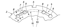
鉄心板2は、電動機の回転子を装着する軸心孔3を穿設した環状外形であって、内径側には巻線を施す多数のスロット4が形成され、外形面には冶工具を係合してスキュー回転させる係合手段として、図示の実施例では4等分位置に所定幅で所定深さの切欠による係合溝5が形成され、各係合溝5の両側に隣接してかしめ結合手段6を設け、かしめ結合手段6を介して上下に隣接する各鉄心板2を一体に連結している。
The
かしめ結合手段6は、図3で要部を拡大して示すように、かしめ部7とその両端の打抜き部8,9で形成され、かしめ部7は打抜き部8,9間の板面を長方形状に半抜き状態で打抜き加工し、図4(a)と図5(a)で示すように、上面側にかしめ凹部7aを下面側にかしめ凸部7bを形成しているが、かしめ凹部7aを形成する内径側と外径側は、軸心から所定の半径寸法R1,R2で同心状をした円弧状面に形成されている。
The caulking coupling means 6 is formed of a
また、かしめ部7のかしめ凹部7aとかしめ凸部7bは図6で誇張して示すように、かしめ凹部7aの内径側の半径寸法R1tと外径側の半径寸法R2t及び、かしめ凸部7bの内径側の半径寸法R1uと外径側の半径寸法R2uの関係を、図6(a)のようにR1t>R1uでR2t>R2uにして内径側に締め代10を設けるか、図6(b)のようにR1t<R1uでR2t<R2uにして外径側に締め代10を設けるように、かしめ部7を半抜き状態で打抜き加工する。
Further, the caulking
これにより、上下に隣接した各鉄心板2,2をかしめ部7でかしめ結合した際に、下方の鉄心板のかしめ凹部7aに対して上方の鉄心板のかしめ凸部7bは、図5(a)のように半径寸法R1による内径側を締め代10にするか、図5(b)のように半径寸法R2による外径側を締め代10とし、内外径のいずれか一方のみを圧接面にしたかしめ結合状態で連結することによって、各鉄心板2,2間は時計方向又は半時計方向に摺動状態で容易に回転させることができる。
Thus, when the upper and lower adjacent
従って、図2(a)及び図4(a)で示すように、かしめ結合された所定枚数の鉄心板2(2a〜2n)を積層し、係合溝5が垂直方向に整合した整列積み(垂直積層)状態の積層鉄心1Aを造り、スキュー用の冶工具を係合溝5に係合して上下に隣接する各鉄心板2,2間を摺動回転させ、打抜き部8又は打抜き部9の範囲内で半時計方向又は時計方向に回転させ、所望のスキュー角度でスキューを付与することができる。
Therefore, as shown in FIGS. 2 (a) and 4 (a), a predetermined number of iron core plates 2 (2a to 2n), which are caulked and joined, are stacked, and the stacked stack in which the
このように、整列積みした積層鉄心1Aにはスロット4に自動巻線機で巻線を施したり、予め巻線したコイルアッセンブリを装着する巻線作業を容易且つ能率的に行うことができると共に、その後に係合溝5をスキュー用の冶工具に係合させ、時計方向又は半時計方向に捻り力を与えると、内外径のいずれか一方面のみが圧接であるから容易にスキュー回転させることができ、垂直方向に対して係合溝5が傾斜したスキュー積み状態の積層鉄心1Bを造ることができる。
In this way, the
次に、整列積みした積層鉄心1Aを順送り金型装置(図示せず)で造る製造方法について、図7のレイアウト図に基づいて説明すると、帯状鉄板11に対して工程(1)でパイロット孔12を打抜きすると共に、このパイロット孔12によって順送り金型装置内で矢印方向へ間欠送りさせ、工程(2)では軸心孔3となる内径打抜きを行い、工程(3)ではスロット4の打抜きを行い、工程(4)では係合溝5と打抜き部8,9の打抜きを行い、工程(5)では1枚目の鉄心板2に対するかしめ部7として計量穴7cを全抜き状態で打ち抜き、工程(6)では2枚目以降の鉄心板2に対するかしめ部7としてかしめ凹部7aとかしめ凸部7bを半抜き状態で打抜き、アイドル工程(7)の後に工程(8)では鉄心外形13の打抜きを行って所定枚数の各鉄心板2を抜き落とす。
Next, a manufacturing method for manufacturing the stacked
また、かしめ部7に計量穴7cを打ち抜いて計量用の鉄心板にする工程(5)では、1枚目の鉄心板2に対しては打抜きパンチを打抜き可能な位置まで突出させて計量穴7cを打ち抜き、2枚目以降の鉄心板2に対しては打抜きパンチを打抜き不能な位置まで後退するように、所定枚数毎に打抜きパンチの突出する長さを制御しており、次工程である工程(6)ではかしめ部7に計量穴7cのない2枚目以降の鉄心板2に対して、一定の長さで突出する打抜きパンチでかしめ凹部7aとかしめ凸部7bが半抜き状態で打抜き加工されるようにしている。
Further, in the step (5) of punching the measuring
そして、かしめ部7に計量穴7cを設けた計量用の鉄心板とかしめ凹部7a及びかしめ凸部7bを設けたその他の鉄心板は、工程(8)で鉄心外形13の打抜きを行ってダイ内に抜き落として積層するが、計量用の鉄心板の計量穴7cには続いて抜き落とされた鉄心板のかしめ凸部7bが嵌合し、さらに続いて抜き落とされてくる鉄心板2のかしめ凸部7bが先の鉄心板2のかしめ凹部7aへ嵌合するようにして順次積層され、次に計量穴7cを設けた計量用の鉄心板が抜き込まれた際に製品分離され、所望の積層枚数にした積層鉄心1Aが得られる。
Then, the measuring iron core plate provided with the measuring
さらに、工程(8)では、先に打抜き加工された鉄心板のかしめ凹部7aに対して、次に打抜き加工された鉄心板のかしめ凸部7bとを、図5のように半径寸法R1による内径側の締め代10又は、半径寸法R2による外径側の締め代10を圧接面にして、かしめ結合状態で相互に連結し、かしめ部7を全抜き状態で打抜き加工した計量用の鉄心板が抜き落とされるまで、所定枚数の鉄心板を各係合溝5が垂直方向に整合した整列積みする連結状態で積層され、これによって整列積みした積層鉄心1Aを造ることができる。
Further, in step (8), the caulking
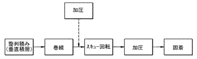
次に、スキュー積みの積層鉄心1Bの製造方法について、図8のブロック図に基づいて説明すると、先に説明したように順送り金型装置を用いて上下に隣接する各鉄心板を、内外径のいずれか一方面の締め代10を圧接面にしたかしめ部7と、その両側に設けてスキュー付与を可能にする打抜き部8,9によるかしめ結合手段6を介して、時計方向又は半時計方向へ摺動可能に仮固着した整列積み(垂直積層)の積層鉄心1Aを造り、順送り金型装置から積層鉄心1Aを取り出す。
Next, a manufacturing method of the skew-stacked
この積層鉄心1Aに対し、スロット4に自動巻線又はコイルアッセンブリによる巻線作業を施した後に、必要に応じて積層鉄心1Aを上下から加圧してかしめ結合すると共に、スキュー用の冶工具を係合溝5に係合させて所望方向に捻りを加え、所望のスキュー角度でスキュー回転をしてスキュー積みした積層鉄心1Bを造り、積層鉄心1Bを上下から加圧してかしめ結合を更に確実にした後に、積層鉄心1Bの外周面をレーザーなどの溶接で一体に固着するが、スキュー前の加圧はその後のスキュー回転を阻害しないように、弱い加圧力にすることが望ましい。
After winding the
次に、図9は図3で示すかしめ結合手段6の変形実施例であって、先の実施例ではかしめ部7の両端に打抜き部8,9を設け、時計方向と反時計方向の双方向にスキュー回転できるようにし、斜めスキューとV字状スキューのいずれも可能な形態としたが、スキュー回転をいずれか一方向にして斜めスキューさせる形態を採ることも可能であり、図9の変形実施例では、かしめ部7の一端に打抜き部8を設けて半時計方向にスキュー回転できるようにし、これにより先の実施例の場合と同様の作用効果を得ることができる。
Next, FIG. 9 shows a modified embodiment of the caulking coupling means 6 shown in FIG. 3. In the previous embodiment, punching
次に、図10はかしめ結合手段6に対するさらに他の変形実施例であって、先の実施例では半抜き状態でかしめ部7を打抜き加工する際に、かしめ凸部7bが水平になるようにしているが、図10の変形実施例によるかしめ結合手段6では、かしめ凸部7bが傾斜状になるように半抜き状態で打抜き加工し、このかしめ凸部7bの上面側に形成されるかしめ凹部7aの底面も傾斜状になるように形成されており、これによってスキュー回転させた際に、各鉄心板2のかしめ部7の干渉が無くなり、上下に隣接する各鉄心板2間の隙間を少なくできるので、密着性が高まって積層厚さの精度を向上することができる。
Next, FIG. 10 shows still another modified embodiment of the caulking coupling means 6. In the previous embodiment, when the
なお、本発明は図示の実施例に限定されることなく要旨の範囲内において各種の変形を採り得るものであって、例えば図示の実施例ではかしめ結合手段6を8個所に設けているが、スキュー積み状態にした積層鉄心1Bの外周面をレーザーなどの溶接で一体に固着する場合には、かしめ結合手段6を設ける個所を少なく(例えば、2個所程度)することが可能であり、またかしめ結合手段6を設ける個所を多くして十分な固着ができる場合には、上記したレーザーなどの溶接による固着を省略することができる。
The present invention is not limited to the illustrated embodiment and can be modified in various ways within the scope of the gist. For example, in the illustrated embodiment, the caulking and coupling means 6 are provided at eight locations. When the outer peripheral surface of the
また、図示の実施例では係合溝5を介してスキュー回転させた際にかしめ結合手段6に対して回転力が十分に伝達され、円滑なスキュー回転によってかしめ部7が緩んだりして隙間ができたりすることを防止できるように、係合溝5の両側近傍にそれぞれかしめ結合手段6を設けているが、この係合溝5を他の場所に設ける形態を採ることも可能であると共に、切欠状の溝穴で形成している係合溝5を、各鉄心板2の外周面から突設させた突起で形成する形態を採ることも可能である。
In the illustrated embodiment, the rotational force is sufficiently transmitted to the caulking coupling means 6 when the skew is rotated through the engaging
また、図示の実施例では工程(5)でかしめ部7に計量穴7cを打ち抜き加工し、工程(6)でかしめ部7にかしめ凹部7aとかしめ凸部7bを打ち抜き加工するようにしているが、この工程(5)と工程(6)を一工程にして、1枚目の鉄心板に対して全抜き状態で計量穴7cを打ち抜き加工する場合と、2枚目以降の鉄心板に対して半抜き状態でかしめ凹部7a及びかしめ凸部7bを打ち抜き加工する場合に、打抜きパンチの下死点の位置を変えるように制御することも可能である。
In the illustrated embodiment, the measuring
さらに、図示の実施例では打抜き加工を容易にするために、かしめ結合手段6の打抜き部8,9を円孔で形成しているが、この打抜き部8,9を角孔で形成する形態を採ることも可能であり、また図示の実施例では電動機の固定子(ステータ)に適用しているが、同様の技術思想に基づいて電動機の回転子(ロータ)に適用することも可能である。
Further, in the illustrated embodiment, the punching
1 積層鉄心
1A (整列積みした)積層鉄心
1B (スキュー積み)積層鉄心
2 鉄心板
3 軸心孔
4 スロット
5 係合溝(スキュー回転用の係合手段)
6 かしめ結合手段
7 かしめ部
7a かしめ凹部
7b かしめ凸部
7c 計量穴
8,9 打抜き部
10 締め代
11 帯状鉄板
12 パイロット孔
13 鉄心外形
DESCRIPTION OF
6 Caulking connection means 7
Claims (5)
各鉄心板において、当該鉄心板の前記軸心から前記かしめ凸部の内径側までの距離が前記軸心から前記かしめ凹部の内径側までの距離より短く、かつ前記軸心から前記かしめ凸部の外径側までの距離が前記軸心から前記かしめ凹部の外径側までの距離より短く、或いは前記軸心から前記かしめ凸部の内径側までの距離が前記軸心から前記かしめ凹部の内径側までの距離より長く、かつ前記軸心から前記かしめ凸部の外径側までの距離が前記軸心から前記かしめ凹部の外径側までの距離より長くなっていることにより、前記かしめ凸部および前記かしめ凹部は、それぞれの内径側または外径側でかしめ結合することを特徴とする積層鉄心。 Each iron core plate provided with an engagement portion on the outer periphery is laminated and connected in an aligned state, and is formed in an arc shape centering on the axis of the iron core plate as a caulking coupling means capable of skew rotation after winding. a slidable and rotatable inside this tightening portion in the circumferential direction Te, the punching portion to secure the skew region provided at one or both ends of the caulking portion, the caulking portion is formed by caulking the recess and the caulking protrusion which is punched in half blanking state A laminated iron core in which the caulking convex portion of one iron core plate adjacent to the upper and lower sides is fitted into the caulking concave portion of the other iron core plate ,
In each iron core plate, the distance from the axis of the iron core plate to the inner diameter side of the caulking convex portion is shorter than the distance from the axis to the inner diameter side of the caulking concave portion, and the caulking convex portion of the caulking convex portion The distance from the shaft center to the outer diameter side of the caulking recess is shorter than the distance from the shaft center to the outer diameter side of the caulking recess, or the distance from the axis to the inner diameter side of the caulking projection is the inner diameter side of the caulking recess And the distance from the axial center to the outer diameter side of the caulking convex part is longer than the distance from the axial center to the outer diameter side of the caulking concave part, and the caulking convex part and The laminated iron core is characterized in that the caulking recesses are caulked and joined on the inner diameter side or the outer diameter side .
Priority Applications (1)
| Application Number | Priority Date | Filing Date | Title |
|---|---|---|---|
| JP2005027186A JP4648716B2 (en) | 2005-02-03 | 2005-02-03 | Laminated iron core and manufacturing method thereof |
Applications Claiming Priority (1)
| Application Number | Priority Date | Filing Date | Title |
|---|---|---|---|
| JP2005027186A JP4648716B2 (en) | 2005-02-03 | 2005-02-03 | Laminated iron core and manufacturing method thereof |
Publications (3)
| Publication Number | Publication Date |
|---|---|
| JP2006217718A JP2006217718A (en) | 2006-08-17 |
| JP2006217718A5 JP2006217718A5 (en) | 2008-03-13 |
| JP4648716B2 true JP4648716B2 (en) | 2011-03-09 |
Family
ID=36980447
Family Applications (1)
| Application Number | Title | Priority Date | Filing Date |
|---|---|---|---|
| JP2005027186A Active JP4648716B2 (en) | 2005-02-03 | 2005-02-03 | Laminated iron core and manufacturing method thereof |
Country Status (1)
| Country | Link |
|---|---|
| JP (1) | JP4648716B2 (en) |
Families Citing this family (3)
| Publication number | Priority date | Publication date | Assignee | Title |
|---|---|---|---|---|
| JP7153423B2 (en) * | 2016-10-13 | 2022-10-14 | 住友重機械工業株式会社 | Rotating electric motor and stator manufacturing method |
| CN111756197B (en) * | 2020-06-12 | 2021-11-30 | 卓尔博(宁波)精密机电股份有限公司 | Manufacturing method of large-rotation skew round buckle self-riveting rotor |
| DE102020211144A1 (en) | 2020-09-03 | 2022-03-03 | Valeo Siemens Eautomotive Germany Gmbh | Stator core, electrical machine and vehicle |
Citations (7)
| Publication number | Priority date | Publication date | Assignee | Title |
|---|---|---|---|---|
| JPS58115846U (en) * | 1982-01-29 | 1983-08-08 | 株式会社東芝 | Laminated structure of core in electric motor |
| JPH0253239U (en) * | 1988-10-06 | 1990-04-17 | ||
| JPH10136618A (en) * | 1996-10-31 | 1998-05-22 | Mitsubishi Electric Corp | Manufacture for laminated iron core |
| JP2001008417A (en) * | 1999-06-21 | 2001-01-12 | Yaskawa Electric Corp | Manufacture of stator for motor |
| JP2001037111A (en) * | 1999-07-15 | 2001-02-09 | Kuroda Precision Ind Ltd | Laminated core and manufacture thereof |
| JP2004007936A (en) * | 2002-04-08 | 2004-01-08 | Ichinomiya Denki:Kk | Method of producing motor core and motor core |
| JP2004328865A (en) * | 2003-04-23 | 2004-11-18 | Mitsui High Tec Inc | Skew-form variable laminated iron core and its manufacturing method |
-
2005
- 2005-02-03 JP JP2005027186A patent/JP4648716B2/en active Active
Patent Citations (7)
| Publication number | Priority date | Publication date | Assignee | Title |
|---|---|---|---|---|
| JPS58115846U (en) * | 1982-01-29 | 1983-08-08 | 株式会社東芝 | Laminated structure of core in electric motor |
| JPH0253239U (en) * | 1988-10-06 | 1990-04-17 | ||
| JPH10136618A (en) * | 1996-10-31 | 1998-05-22 | Mitsubishi Electric Corp | Manufacture for laminated iron core |
| JP2001008417A (en) * | 1999-06-21 | 2001-01-12 | Yaskawa Electric Corp | Manufacture of stator for motor |
| JP2001037111A (en) * | 1999-07-15 | 2001-02-09 | Kuroda Precision Ind Ltd | Laminated core and manufacture thereof |
| JP2004007936A (en) * | 2002-04-08 | 2004-01-08 | Ichinomiya Denki:Kk | Method of producing motor core and motor core |
| JP2004328865A (en) * | 2003-04-23 | 2004-11-18 | Mitsui High Tec Inc | Skew-form variable laminated iron core and its manufacturing method |
Also Published As
| Publication number | Publication date |
|---|---|
| JP2006217718A (en) | 2006-08-17 |
Similar Documents
| Publication | Publication Date | Title |
|---|---|---|
| JP4176121B2 (en) | Rotor laminated iron core and manufacturing method thereof | |
| EP2120313B1 (en) | Electrical motor and method for manufacturing the same | |
| US8106561B2 (en) | Laminated core and method for manufacturing the same | |
| JP6234457B2 (en) | Stator | |
| JP5859112B2 (en) | Rotating electric machine armature and method of manufacturing rotating electric machine armature | |
| WO2012057100A1 (en) | Divided iron core and manufacturing method therefor | |
| JP4934402B2 (en) | Armature manufacturing method and progressive mold apparatus | |
| JP5190318B2 (en) | Permanent magnet type laminated iron core and manufacturing method thereof | |
| WO2009093524A1 (en) | Laminated iron core for rotor | |
| JP5717973B2 (en) | Laminated iron core and method for manufacturing the same | |
| EP3474427B1 (en) | Manufacturing method of core of rotating electrical machine, and core of rotating electrical machine | |
| JP4648716B2 (en) | Laminated iron core and manufacturing method thereof | |
| JP2001339881A (en) | Stator for dynamo-electric machine and manufacturing method thereof | |
| JP5251384B2 (en) | Laminated core and manufacturing method thereof | |
| JP2007089326A (en) | Stacked stator core, and its manufacturing method and its manufacturing device | |
| JP5103292B2 (en) | Rotor laminated iron core and manufacturing method thereof | |
| JP3964306B2 (en) | Method for manufacturing stator laminated iron core of electric motor | |
| JP5975948B2 (en) | Rotating electric machine laminated iron core, rotating electric machine stator and rotating electric machine laminated iron core manufacturing method | |
| JP5432311B2 (en) | Rotor laminated iron core and manufacturing method thereof | |
| JP4482550B2 (en) | Laminated iron core | |
| JP2008043130A (en) | Stator core of axial capacitor motor and its manufacturing method | |
| JP2005278298A (en) | Split core, skewed split laminated core, skewed laminated annular core, split laminated core skew forming apparatus, stator and electric motor | |
| JP2009100537A (en) | Method for manufacturing core in rotor with permanent magnet and core | |
| JP5815336B2 (en) | Rotating electric machine laminated iron core and method of manufacturing rotating electric machine laminated iron core | |
| JP2008022603A (en) | Armature for dynamo-electric machine |
Legal Events
| Date | Code | Title | Description |
|---|---|---|---|
| A521 | Request for written amendment filed |
Free format text: JAPANESE INTERMEDIATE CODE: A523 Effective date: 20080125 |
|
| A621 | Written request for application examination |
Free format text: JAPANESE INTERMEDIATE CODE: A621 Effective date: 20080125 |
|
| A977 | Report on retrieval |
Free format text: JAPANESE INTERMEDIATE CODE: A971007 Effective date: 20100617 |
|
| A131 | Notification of reasons for refusal |
Free format text: JAPANESE INTERMEDIATE CODE: A131 Effective date: 20100622 |
|
| A521 | Request for written amendment filed |
Free format text: JAPANESE INTERMEDIATE CODE: A523 Effective date: 20100819 |
|
| TRDD | Decision of grant or rejection written | ||
| A01 | Written decision to grant a patent or to grant a registration (utility model) |
Free format text: JAPANESE INTERMEDIATE CODE: A01 Effective date: 20101124 |
|
| A01 | Written decision to grant a patent or to grant a registration (utility model) |
Free format text: JAPANESE INTERMEDIATE CODE: A01 |
|
| A61 | First payment of annual fees (during grant procedure) |
Free format text: JAPANESE INTERMEDIATE CODE: A61 Effective date: 20101210 |
|
| FPAY | Renewal fee payment (event date is renewal date of database) |
Free format text: PAYMENT UNTIL: 20131217 Year of fee payment: 3 |
|
| R150 | Certificate of patent or registration of utility model |
Ref document number: 4648716 Country of ref document: JP Free format text: JAPANESE INTERMEDIATE CODE: R150 Free format text: JAPANESE INTERMEDIATE CODE: R150 |
|
| R250 | Receipt of annual fees |
Free format text: JAPANESE INTERMEDIATE CODE: R250 |
|
| R250 | Receipt of annual fees |
Free format text: JAPANESE INTERMEDIATE CODE: R250 |
|
| R250 | Receipt of annual fees |
Free format text: JAPANESE INTERMEDIATE CODE: R250 |
|
| R250 | Receipt of annual fees |
Free format text: JAPANESE INTERMEDIATE CODE: R250 |
|
| R250 | Receipt of annual fees |
Free format text: JAPANESE INTERMEDIATE CODE: R250 |
|
| R250 | Receipt of annual fees |
Free format text: JAPANESE INTERMEDIATE CODE: R250 |
|
| R250 | Receipt of annual fees |
Free format text: JAPANESE INTERMEDIATE CODE: R250 |
|
| R250 | Receipt of annual fees |
Free format text: JAPANESE INTERMEDIATE CODE: R250 |
|
| R250 | Receipt of annual fees |
Free format text: JAPANESE INTERMEDIATE CODE: R250 |
|
| R250 | Receipt of annual fees |
Free format text: JAPANESE INTERMEDIATE CODE: R250 |
|
| R250 | Receipt of annual fees |
Free format text: JAPANESE INTERMEDIATE CODE: R250 |