JP3774565B2 - Thin film formation method - Google Patents
Thin film formation method Download PDFInfo
- Publication number
- JP3774565B2 JP3774565B2 JP13263798A JP13263798A JP3774565B2 JP 3774565 B2 JP3774565 B2 JP 3774565B2 JP 13263798 A JP13263798 A JP 13263798A JP 13263798 A JP13263798 A JP 13263798A JP 3774565 B2 JP3774565 B2 JP 3774565B2
- Authority
- JP
- Japan
- Prior art keywords
- thin film
- film forming
- water
- electron gun
- repellent
- Prior art date
- Legal status (The legal status is an assumption and is not a legal conclusion. Google has not performed a legal analysis and makes no representation as to the accuracy of the status listed.)
- Expired - Lifetime
Links
Images
Description
【0001】
【発明の属する技術分野】
本発明は薄膜形成方法に関し、特に基材もしくは基材上のコート膜の表面処理としての薄膜形成方法に関する。
【0002】
【従来の技術】
種々の基材の表面に防汚・防水・防塵の機能を持たせるために有機系薄膜を形成することは広くおこなわれている。かかる薄膜の形成方法としては、有機溶媒に希釈した撥水物質を基材に直接塗布する方法(特開昭60−40254号公報)、上記の溶液に浸漬する方法(特開昭61−130902号公報)、セラミックスに含浸させた有機物質を真空槽中で蒸発させる方法(特開平4−72055号公報)、金属のウールに含浸させた有機物質を真空槽中で蒸発させる方法(特開平6−340966号公報)などが知られている。
【0003】
【発明が解決しようとする課題】
しかしながら、前述のような薄膜の形成方法は、それぞれ以下のような欠点を有する。
撥水性物質を基材に直接塗布する方法は、撥水性物質を溶媒に溶解しなければならないほか、塗布時にムラになりやすい。
【0004】
上記の希釈溶液に浸漬する方法は、希釈に大量の溶媒を使用するほか、真空蒸着などの薄膜形成処理後の基板上に成膜する場合、真空槽から取り出した後にさらに別な工程を必要とするなど手間がかかる。
【0005】
セラミックスに含浸させた有機系物質を加熱蒸発させる方法は、真空中で処理が可能で通常の真空薄膜形成工程内に組み込めるなどのメリットもあるが、一般に有機系の物質は絶緑体である場合が多く、真空蒸着装置の蒸発源として普及している電子銃を用いると、表面に当たった電子線によって照射を受けた部分がマイナスに帯電してしまい、電子線が反射され効率よく加熱することができない場合がある。さらに加熱を続けると、急速に絶縁が破壊され、セラミックスに含浸された有機物ばかりでなく含浸母体であるセラミックスまでが溶解・蒸発し、撥水性を持たせたい基材上に付着し、撥水性能の低下や、薄膜の特性変化を起こすことがある。
【0006】
金属のウールに含浸させた有機物質を蒸発させる方法は上記の他の方法に比べて簡単であり、電子ビームによる加熱も容易であるが、コストを下げるため銅やアルミニウムなどの安価な金属を使用すると、それらの金属の融点が600℃乃至800℃のため、加熱条件を誤ると金属ウールが溶解し、その溶解した金属が蒸発して基材に着色や接触角の低下などの悪影響を与えてしまうことがある。さらに、金属は熱伝導率が大きいので加熱時の暖まり方が非常に早く、蒸発量の調節が難しい。
【0007】
本発明は、上記のような問題点に鑑みてなされたもので、その課題は、基材上に有機系の薄膜を電子銃を用いて簡単な工程で低価格に、なおかつ安定的に実現しうる薄膜形成方法を提供することである。
【0008】
【課題を解決するための手段】
即ち、本発明は、薄膜形成物質を保持させた多孔質材料の表面に導電性物質を付着させてなる薄膜形成材料を減圧下で電子銃を用いて加熱することにより、前記多孔質材料から薄膜形成物質を蒸発させ、該薄膜形成物質の薄膜を形成することを特徴とする薄膜形成方法である。
前記薄膜形成物質が撥水性の有機物質、特に有機シリコーン類化合物またはパーフルオロアルキル基含有化合物であるのが好ましい。
前記薄膜形成物質を保持させた多孔質材料の表面に導電性物質として、例えばカーボンペーストまたは銀ペーストを付着させてなるのが好ましい。
【0010】
【発明の実施の形態】
以下、本発明を詳細に説明する。
本発明の薄膜形成材料は、好ましくは有機系の薄膜形成物質を含浸させた多孔質材料に導電性を付与したものであり、該薄膜形成物質を蒸発により基材上に堆積させる。そしてその蒸発のための熱源として好ましくは電子銃が使用可能であるという点で特徴的である。
【0011】
本発明において「導電性の付与」とは、有機系物質の含浸母体である多孔質材料に有機系物質を含浸させた後、表面に導電性物質を塗布あるいは付着させることをさす。
【0012】
本発明において有機系薄膜形成物質を含浸させる多孔質材料は、有機系物質が含浸されれば特に制限はなく、例えば多孔質セラミックス、多孔質金属などがあげられる。
【0013】
また、含浸される有機薄膜形成物質は、目的とする薄膜に要求される機能に応じて選ばれる。例えば、撥水性や撥油性などの防汚性・防塵性を持たせるためには薄膜状態でこれらの機能を実現し得るような薄膜形成物質を用いる。これらは撥水性を持つような有機シリコーン類化合物、またはパーフルオロアルキル基含有化合物はであれば特に限定されるものではない。例えば有機シリコーン類化合物の例としてはジエトキシジメチルシラン、トリエトキシメチルシランなどがあげられ、またパーフルオロアルキル基含有化合物の例としては、化学式n−C8 F17CH2 CH2 Si(NH2 )3 で示される2−(パーフルオロオクチル)エチルトリアミノシランや、化学式n−C6 F13CH2 CH2 Si(NH2 )3 で示される2−(パーフルオロヘキシル)エチルトリアミノシラン、化学式n−C8 F17CH2CH2Si(OCH3)3で示される2−(パーフルオロオクチル)エチルトリメトキシシランなどがあげられる。これら化合物は単独ではもちろんのこと2種以上組み合わせて用いても良い。
【0014】
導電性を付与させるための物質としては、有機溶媒に導電性物貿を分散させた溶液や、導電性物質を樹脂に練り込んでペースト状にしたものなどがあげられる。導電性物質の例としては金、銀、銅、カーボン、アルミニウムなどがあげられる。
【0015】
導電性の付与方法は、上記の薄膜形成物質を保持させた多孔質材料を導電性物質が分散された溶液に浸漬し、導電性の粒子を多孔質体の表面に付着させ、有機溶媒を蒸発させる方法、薄膜形成物質を保持させた多孔質材料にペースト状にした導電性物質を直接塗布する方法、ペースト状にした導電性物質を有機溶媒に希釈し、そこに薄膜形成物質を保持させた多孔質材料を浸漬する方法などがあげられる。
【0016】
本発明では、上述したような薄膜形成材料に保持された薄膜形成物質を蒸発させ、所定の基材の上に堆積させて薄膜を形成し、基材の表面に目的とする機能を付与する。
【0017】
その具体例としては、例えば上述したような薄膜形成材料を用い、該薄膜形成材料に保持された撥水薄膜形成物質を真空中で加熱蒸発させ基材の表面あるいは基材上に形成された無機コート膜等の薄膜上に撥水性を付与する。
【0018】
該撥水性薄膜の蒸発方法としては電子銃を用いることができる。上述したような有機薄膜形成物質は、導電性を有しないことが多く、該有機薄膜形成物質を保持するための多孔質材料が導電性であっても、有機系物質の含浸によってその表面が導電性を持たない有機系薄膜形成物質で被われてしまうため、電子ビームをその多孔質体表面に照射すると表面で帯電が起こり電子が反射されてしまう。したがって、該多孔質体は電子銃では加熱されないことが多い。
【0019】
本発明の薄膜形成材料は上述した導電性物質の含浸によって、表面を電子が流れ、その電子の運動エネルギーによつて薄膜形成物質が加熱される。
【0020】
真空中における薄膜形成物質の蒸発の条件は、薄膜形成物質および基材の種類、状態により条件を適宜決定することが望ましいが、例えばプラスチック基材上にSiO2 などの無機コート薄膜を形成した光学レンズ上に、撥水物質を加熱蒸発および堆積させて薄膜を形成する場合には、真空度10-6から10-3Torrで行うことがより望ましい。
【0021】
本発明においては、薄膜を形成する基材は特に限定されない。例えば、撥水性の薄膜形成物質を用いて撥水性薄膜を形成する場合では、最表面が無機物質からなるコート膜であるようなものであれば特に限定されるものではないが、具体例としては、無機反射防止膜が形成されたガラスレンズ、プラスチックレンズ、光学フィルター、自動車のフロントガラス、ディスプレイパネルなどが挙げられる。
【0022】
【実施例】
以下、本発明について図面を参照し、実施例に沿つて詳細に説明するが、本発明は以下に限定されるものではない。
【0023】
実施例1
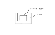
酸化ジルコニウム粉末にPVAの3%水溶液をバインダーとして添加し、直径15mm、高さ10mmにプレスした後に、電気炉にて1300℃で焼結して撥水性物質の含浸母体とした。この酸化ジルコニウム焼結体1を図1の様な直径20mm、深さ15mmの円筒形の容器2に入れ、かかる容器2に化学式n−C8 F17CH2 CH2 Si(NH2 )3 で表されるパーフルオロアルキル基含有化合物をメタキシレンヘキサフロライドで3%に希釈した撥水処理用の溶液をピペットを用いてlml含浸させた。さらに、これを70℃で20分間乾燥し、溶剤成分を蒸発させた。
【0024】
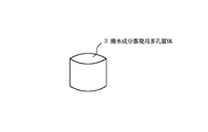
次に、カーボンアクリル樹脂(日本電子製:商品名:ドータイトXC−12)を酢酸ブチルにて10%に希釈した溶液に、上記の酸化ジルコニウム焼結体ペレット1を30秒間浸漬した後、l0分間乾燥し導電性の付与された撥水成分蒸発用多孔質体3とした(図2)。
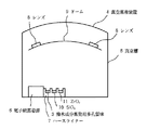
次に、それを図3の様な真空蒸着装置(シンクロンBMC850)4の真空槽5内の電子銃蒸発源6のハースライナー7にSiO2(10)とZrO2(11)とともにセットした。
【0025】
次に、ジエチレングリコールビスアリルカーボネート樹脂からなる合成樹脂製レンズ8を上記真空蒸着装置4のドーム9上にセットし、電子銃蒸発源6を用いてSiO2 (10)とZrO2 (11)の薄膜を交互に膜構成が基板側からSiO2 約3μm、ZrO2 約0.015μm、SiO2 約0.02μm、ZrO2 約0.1μm、SiO2 約0.08μmとなるように積層し反射防止膜付きレンズとした。
【0026】
この反射防止膜付き合成樹脂レンズを蒸着終了後、真空槽5から出さずに、先に同じ電子銃6のハースライナー7にセットした撥水成分蒸発用多孔質体3を電子銃条件が加速電圧6kV、エミッション電流5mA、ビームスポットサイズ直径約20mmで2分間加熱しパーフルオロアルキル基含有化合物を蒸発させ、撥水薄膜の形成を行った。
【0027】
蒸着終了後、合成樹脂製レンズ8を真空槽5から取り出し、レンズの水に対する接触角を協和界面科学製CA−Z型接触角計を用いて測定した。またその測定後アセトンを含ませたレンズペーパーで約lKgの重量をかけ、50住復擦り、その後再度接触角を測定し、その変化を観察した。
その評価結果は表1に示すとおり良好であつた。
【0028】
実施例2
酸化ジルコニウム粉末にPVAの3%水溶液をバインダーとして添加し、直径15mm、高さ10mmにプレスした後に、電気炉にて1300℃で焼結して撥水性物質の含浸母体とした。この酸化ジルコニウム焼結体1を図1の様な直径20mm、深さ15mmの円筒形の容器2に入れ、かかる容器2に化学式n−C8 F17CH2 CH2 Si(NH2 )3 で表されるパーフルオロアルキル基含有化合物をメタキシレンヘキサフロライドで3%に希釈した撥水処理用の溶液をピペットを用いてlml含浸させた。さらに、これを70℃で20分間乾燥し、溶剤成分を蒸発させた。
【0029】
次に、銀−アクリル樹脂(日本電子製:商品名:ドータイトD−550)を酢酸ブチルにて10%に希釈した溶液に、上記の酸化ジルコニウムペレット1を30秒間浸漬した後、10分間乾燥し導電性の撥水成分蒸発用多孔質体3とした(図2)。次に、それを図3の様な真空蒸着装置(シンクロンBMC850)4の真空槽5内の電子銃蒸発源6のハースライナー7にセットした。
【0030】
続いて実施例1と同様の手順で作成した反射防止膜付きジエチレングリコールビスアリルカーボネート樹脂からなる合成樹脂製レンズ8を蒸着終了後、真空槽5から出さずに、先に同じ電子銃6のハースライナー7にセットした撥水成分蒸発用多孔質体3を電子銃条件が加速電圧6kV、エミッション電流5mA、ビームスポットサイズ直径約20mmで2分間加熱し、パーフルオロアルキル基含有化合物を蒸発させ、撥水薄膜の形成を行った。
【0031】
蒸着終了後、合成樹脂製レンズ8を真空槽5から取り出し、レンズの水に対する接触角を協和界面科学製CA−Z型接触角計を用いて測定した。またその測定後、アセトンを含ませたレンズペーパーで約lKgの重量をかけ、50住復擦り、その後再度接触角を測定し、その変化を観察した。
その評価結果は表1に示すとおり良好であった。
【0032】
実施例3
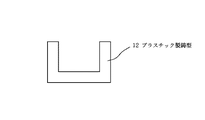
市販の石膏(サンエス石膏株式会社製、商品名焼石膏)50gに水25gを添加し1分間よく撹拌した後、その一部を図4の様な直径18mm、深さ10mmのプラスチック製の鋳型12に流し込んで室温で1時間乾燥させた。これに化学式n−C8 F17CH2 CH2 Si(NH2 )3 で表わされるパーフルオロアルキル基含有化合物をメタキシレンヘキサフロライドで3%に希釈した撥水処理用の溶液をピペットを用いてlml含浸させた。さらにこれを70℃で20分間乾燥後、鋳型12から取り出し、撥水成分蒸発用多孔質体3とした(図2)。
【0033】
次に、カーボンアクリル樹脂(日本電子製:商品名:ドータイトXC−12)を酢酸ブチルにて10%に希釈した溶液に、上記の石膏を30秒間浸漬し、導電性の撥水成分蒸発用多孔質体とした。それを図3のような真空蒸着装置(シンクロンBMC850)4の真空槽5内の電子銃蒸発源6のハースライナー7にセットした。
【0034】
続いて実施例1と同様の手順で作成した反射防止膜付きジエチレングリコールビスアリルカーボネート樹脂からなる合成樹脂製レンズ8を蒸着終了後、真空槽5から出さずに、先に同じ電子銃のハースライナー7にセットした撥水成分蒸発用多孔質体3を電子銃条件、加速電圧6kV、エミッション電流5mA、ビームスポットサイズ直径約20mmで2分間加熱し、パーフルオロアルキル基含有化合物を蒸発させ、撥水薄膜の形成を行った。
【0035】
蒸着終了後、合成樹脂製レンズ8を真空槽5から取り出し、レンズの水に対する接触角を協和界面科学製CA−Z型接触角計を用いて測定した。またその測定後アセトンを含ませたレンズペーパーで約lKgの重量をかけ、50住復擦り、その後再度接触角を測定し、その変化を観察した。
その評価結果は表1に示すとおり良好であった。
【0036】
実施例4
酸化ジルコニウム粉末にPVAの3%水溶液をバインダーとして添加し、直径15mm、高さ10mmにプレスした後に、電気炉にて1300℃で焼結。撥水性物質の含浸母体とした。この酸化ジルコニウム焼結体1を図1の様な直径20mm、深さ15mmの円筒形の容器2に入れ、かかる容器2に化学式n−C8 F17CH2 CH2 Si(OCH3 )3 で表されるパーフルオロアルキル基含有化合物をピペットを用いて0.5ml含浸させた。
【0037】
次に、銀−アクリル樹脂(目本電子製:商品名:ドータイトD−550)を酢酸ブチルにて10%に希釈した溶液に、上記の酸化ジルコニウムペレットを30秒間浸漬し、導電性の撥水成分蒸発用多孔質体3とした(図2)。次に、それを図3の様な真空蒸着装置(シンクロンBMC850)4の真空槽5内の電子銃蒸発源6のハースライナー7にセットした。
【0038】
続いて実施例1と同様の手順で作成した反射防止膜付きジエチレングリコールビスアリルカーボネート樹脂からなる合成樹脂製レンズ8を蒸着終了後、真空槽5から出さずに、先に同じ電子銃6のハースライナー7にセットした撥水成分蒸発用多孔質体3を電子銃条件が加速電圧6kV、エミッション電流5mA、ビームスポットサイズ直径約20mmで2分間加熱しパーフルオロアルキル基含有化合物を蒸発させ、撥水薄膜の形成を行った。
【0039】
蒸着終了後、合成樹脂製レンズ8を真空槽5から取り出し、レンズの水に対する接触角を協和界面科学製CA−Z型接触角計を用いて測定した。またその測定後アセトンを含ませたレンズペーパーで約lKgの重量をかけ、50住復擦り、その後再度接触角を測定し、その変化を観察した。
その評価結果は表1に示すとおり良好であった。
【0040】
比較例1
酸化ジルコニウム粉末にPVAの3%水溶液をバインダーとして添加し、直径15mm、高さ10mmにプレスした後に、電気炉にて1300℃で焼結して撥水性物質の含浸母体とした。この酸化ジルコニウム焼結体1を図1の様な直径20mm、深さ15mmの円筒形の容器2に入れ、かかる容器2に化学式n−C8 F17CH2 CH2 Si(NH2 )3 で表わされるパーフルオロアルキル基含有化合物をメタキシレンヘキサフロライドで3%に希釈した撥水処理用の溶液をピペットを用いてlml含浸させた。さらにこれを70℃で20分間乾燥し、溶剤成分を蒸発させた。それを図3の様な真空蒸着装置(シンクロンBMC850)4の真空槽5内の電子銃蒸発源6のハースライナー7にセットした。
【0041】
続いて実施例1と同様の手順で作成した反射防止膜付きジエチレングリコールビスアリルカーボネート樹脂からなる合成樹脂製レンズ8を蒸着終了後、真空槽5から出さずに、先に同じ電子銃6のハースライナー7にセットした撥水成分蒸発用材料3を電子銃条件が加速電圧6kV、エミッション電流10mA、ビームスポットサイズ直径約20mmで2分間加熱した。しかし、撥水成分蒸発用多孔質体3は加熱赤熱されず、撥水成分の蒸発を示す真空度の悪化は見られなかった。
【0042】
また、蒸着終了後、合成樹脂製レンズ8を真空槽5から取り出し、レンズの水に対する接触角を協和界面科学製CA−Z型接触角計を用いて測定したところ、その接触角は表1のようにきわめて低く、満足のゆくものではなかった。
【0043】
比較例2
比較例1と同様の手順で作成した酸化ジルコニウムの撥水成分蒸発用多孔質体3(図2)を図3の様な真空蒸着装置(シンクロンBMC850)4の真空槽5内の電子銃蒸発源6のハースライナー7にセットした。
【0044】
続いて実施例1と同様の手順で作成した反射防止膜付きジエチレングリコールビスアリルカーボネート樹脂からなる合成樹脂製レンズ8を蒸着終了後、真空槽5から出さずに、先に同じ電子銃6のハースライナー7にセットした撥水成分蒸発用多孔質体3を電子銃条件が加速電圧6kV、エミッション電流150mA、ビームスポットサイズ直径約20mmで2分間加熱した。ペレットは加熱赤熱したが、含浸母体の酸化ジルコニウム焼結体1にも蒸発が見られ、蒸着終了後、真空槽5から取り出した合成樹脂製レンズ8の反射色は通常の反射色である淡緑色から黄色に変化しており所望の特性から変化していた。
【0045】
また、レンズの水に対する接触角を協和界面科学製CA−Z型接触角計を用いて測定したところ、初期のその接触角は表1のように良好であったが、アセトンを含ませたレンズペーパーで約lKgの重量をかけ、50住復擦り、その後再度接触角を測定するとその接触角はきわめて低く、満足のゆくものではなかった。
【0046】
【表1】

【発明の効果】
以上詳述したように、本発明の薄膜形成方法により、所定の基材上に低コストでなおかつ簡易な操作により、高品質の薄膜を得ることができる。
【図面の簡単な説明】
【図1】本発明の薄膜形成材料の調製時における多孔質体を含浸用の容器に充填した状態を模式的に示す断面図である。
【図2】本発明の実施例で使用する撥水成分蒸発用多孔質体を示す説明図である。
【図3】本発明の実施例で使用する真空蒸着装置の構造を示す模式図である。
【図4】本発明の薄膜形成材料の調製時における石膏をプラスチック製の鋳型に充填する状態を模式的に示す断面図である。
【符号の説明】
1 ジルコニウム焼結体
2 容器
3 撥水成分蒸発用多孔質体
4 真空蒸着装置
5 真空槽
6 電子銃蒸発源
7 ハースライナー
8 レンズ
9 ドーム
10 SiO2
11 ZrO2
12 プラスチック製鋳型[0001]
BACKGROUND OF THE INVENTION
The present invention relates to a thin film forming method , and more particularly to a thin film forming method as a surface treatment of a substrate or a coating film on the substrate.
[0002]
[Prior art]
Forming organic thin films in order to impart antifouling, waterproof, and dustproof functions to the surfaces of various substrates is widely performed. As a method for forming such a thin film, a method of directly applying a water-repellent substance diluted in an organic solvent to a substrate (Japanese Patent Laid-Open No. 60-40254), a method of immersing in the above solution (Japanese Patent Laid-Open No. 61-130902). Gazette), a method of evaporating an organic substance impregnated in ceramics in a vacuum chamber (JP-A-4-72055), and a method of evaporating an organic substance impregnated in metal wool in a vacuum chamber (JP-A-6-6 No. 340966) is known.
[0003]
[Problems to be solved by the invention]
However, the methods for forming a thin film as described above have the following drawbacks.
In the method of directly applying the water repellent material to the substrate, the water repellent material must be dissolved in a solvent, and unevenness is likely to occur during application.
[0004]
In addition to using a large amount of solvent for dilution, the method of immersing in the above-mentioned diluted solution requires a further process after taking out from the vacuum chamber when forming a film on a substrate after thin film formation processing such as vacuum deposition. It takes time and effort.
[0005]
The method of heating and evaporating the organic material impregnated in ceramics has the advantage that it can be processed in vacuum and can be incorporated into the normal vacuum thin film formation process, but in general the organic material is a green body When using an electron gun that is widely used as the evaporation source of vacuum deposition equipment, the part irradiated by the electron beam hitting the surface is negatively charged, and the electron beam is reflected and heated efficiently. May not be possible. If the heating is continued further, the insulation is rapidly destroyed, and not only the organic matter impregnated in the ceramic but also the ceramic that is the impregnated matrix dissolves and evaporates, and adheres to the base material that is desired to have water repellency. May cause deterioration of the film and changes in the properties of the thin film.
[0006]
The method of evaporating the organic material impregnated in metal wool is simpler than the other methods described above, and it is easy to heat with an electron beam, but in order to reduce costs, inexpensive metals such as copper and aluminum are used. Then, since the melting points of these metals are 600 ° C. to 800 ° C., if the heating conditions are incorrect, the metal wool will dissolve, and the dissolved metal will evaporate, causing adverse effects such as coloring and lowering the contact angle on the substrate. It may end up. Furthermore, since metal has a high thermal conductivity, it is very quickly heated during heating, and it is difficult to adjust the amount of evaporation.
[0007]
The present invention has been made in view of the problems as described above, and the problem is to realize an organic thin film on a base material at a low cost and in a stable manner using an electron gun. A thin film forming method is provided.
[0008]
[Means for Solving the Problems]
That is, the present invention provides a method for heating a thin film forming material obtained by attaching a conductive substance to the surface of a porous material holding a thin film forming substance using an electron gun under reduced pressure, thereby forming a thin film from the porous material. A thin film forming method characterized in that a forming material is evaporated to form a thin film of the thin film forming material.
The thin film-forming substance is preferably a water-repellent organic substance, particularly an organic silicone compound or a perfluoroalkyl group-containing compound.
For example, a carbon paste or a silver paste is preferably attached as a conductive substance to the surface of the porous material holding the thin film forming substance.
[0010]
DETAILED DESCRIPTION OF THE INVENTION
Hereinafter, the present invention will be described in detail.
The thin film-forming material of the present invention is preferably a porous material impregnated with an organic thin film-forming substance, imparted with conductivity, and the thin-film forming substance is deposited on a substrate by evaporation. The electron gun is preferably used as a heat source for the evaporation.
[0011]
In the present invention, “giving conductivity” refers to impregnating a porous material, which is a base material impregnated with an organic material, with an organic material, and then applying or adhering the conductive material to the surface.
[0012]
In the present invention, the porous material impregnated with the organic thin film-forming substance is not particularly limited as long as it is impregnated with the organic substance, and examples thereof include porous ceramics and porous metals.
[0013]
The organic thin film forming material to be impregnated is selected according to the function required for the target thin film. For example, in order to provide antifouling and dustproof properties such as water repellency and oil repellency, a thin film forming material that can realize these functions in a thin film state is used. These are not particularly limited as long as they are water-repellent organic silicone compounds or perfluoroalkyl group-containing compounds. For example, examples of the organic silicone compound include diethoxydimethylsilane, triethoxymethylsilane, and the like, and examples of the perfluoroalkyl group-containing compound include the chemical formula nC 8 F 17 CH 2 CH 2 Si (NH 2 ) 2- (or perfluorooctyl) ethyltrimethoxysilane amino silane represented by 3, represented by the chemical formula n-C 6 F 13 CH 2 CH 2 Si (NH 2) 3 2- ( perfluorohexyl) ethyl triamino silanes, formula n such as 2- (perfluorooctyl) ethyltrimethoxysilane represented by -C 8 F 17 CH 2 CH 2 Si (OCH 3) 3 and the like. These compounds may be used alone or in combination of two or more.
[0014]
Examples of the substance for imparting conductivity include a solution in which a conductive material is dispersed in an organic solvent, and a paste obtained by kneading a conductive substance into a resin. Examples of the conductive material include gold, silver, copper, carbon, and aluminum.
[0015]
The conductivity is imparted by immersing the porous material holding the thin film forming substance in a solution in which the conductive substance is dispersed, attaching the conductive particles to the surface of the porous body, and evaporating the organic solvent. A method of directly applying a paste-like conductive substance to a porous material holding a thin film-forming substance, diluting the paste-like conductive substance in an organic solvent, and holding the thin film-forming substance there For example, a method of immersing a porous material can be used.
[0016]
In the present invention, the thin film forming substance held in the thin film forming material as described above is evaporated and deposited on a predetermined base material to form a thin film, and a desired function is imparted to the surface of the base material.
[0017]
As a specific example, for example, the above-described thin film forming material is used, and the water-repellent thin film forming substance held in the thin film forming material is heated and evaporated in vacuum to form an inorganic material formed on the surface of the base material or on the base material. Water repellency is imparted on a thin film such as a coating film.
[0018]
An electron gun can be used as a method for evaporating the water-repellent thin film. Organic thin film forming substances as described above often have no electrical conductivity, and even if the porous material for holding the organic thin film forming substance is conductive, the surface of the organic thin film forming substance is made conductive by impregnation with the organic substance. Therefore, when the electron beam is irradiated onto the surface of the porous body, the surface is charged and the electrons are reflected. Therefore, the porous body is often not heated by an electron gun.
[0019]
In the thin film forming material of the present invention, electrons impinge on the surface due to the impregnation of the conductive material described above, and the thin film forming material is heated by the kinetic energy of the electrons.
[0020]
The conditions for evaporating the thin film-forming substance in a vacuum are preferably determined appropriately depending on the type and state of the thin film-forming substance and the substrate. For example, an optical film in which an inorganic coated thin film such as SiO 2 is formed on a plastic substrate When a thin film is formed by heating and evaporating and depositing a water repellent material on the lens, it is more preferable to carry out at a vacuum degree of 10 −6 to 10 −3 Torr.
[0021]
In the present invention, the base material on which the thin film is formed is not particularly limited. For example, in the case of forming a water-repellent thin film using a water-repellent thin film-forming substance, there is no particular limitation as long as the outermost surface is a coat film made of an inorganic substance. Examples thereof include a glass lens, a plastic lens, an optical filter, an automobile windshield, and a display panel on which an inorganic antireflection film is formed.
[0022]
【Example】
Hereinafter, the present invention will be described in detail with reference to the drawings with reference to the drawings. However, the present invention is not limited to the following.
[0023]
Example 1
A 3% aqueous solution of PVA was added as a binder to zirconium oxide powder, pressed to a diameter of 15 mm and a height of 10 mm, and then sintered at 1300 ° C. in an electric furnace to obtain an impregnated matrix of a water repellent material. This zirconium oxide sintered body 1 is put into a cylindrical container 2 having a diameter of 20 mm and a depth of 15 mm as shown in FIG. 1, and the chemical formula nC 8 F 17 CH 2 CH 2 Si (NH 2 ) 3 is put in the container 2. A water repellent treatment solution obtained by diluting the represented perfluoroalkyl group-containing compound with meta-xylene hexafluoride to 3% was impregnated using a pipette. Furthermore, this was dried at 70 ° C. for 20 minutes to evaporate the solvent component.
[0024]
Next, the zirconium oxide sintered pellet 1 is immersed for 30 seconds in a solution obtained by diluting a carbon acrylic resin (manufactured by JEOL Ltd .: trade name: Dotite XC-12) to 10% with butyl acetate, and then 10 minutes. It was set as the porous body 3 for evaporating the water repellent component which was dried and provided with conductivity (FIG. 2).
Next, it was set together with SiO 2 (10) and ZrO 2 (11) on the hearth liner 7 of the electron gun evaporation source 6 in the vacuum chamber 5 of the vacuum vapor deposition apparatus (Syncron BMC850) 4 as shown in FIG.
[0025]
Next, a
[0026]
After the deposition of the synthetic resin lens with the antireflection film, the porous body 3 for evaporating the water-repellent component previously set on the hearth liner 7 of the same electron gun 6 without being taken out of the vacuum chamber 5 is accelerated by the electron gun condition. The perfluoroalkyl group-containing compound was evaporated by heating at 6 kV, an emission current of 5 mA, and a beam spot size diameter of about 20 mm for 2 minutes to form a water-repellent thin film.
[0027]
After vapor deposition, the
The evaluation results were good as shown in Table 1.
[0028]
Example 2
A 3% aqueous solution of PVA was added as a binder to zirconium oxide powder, pressed to a diameter of 15 mm and a height of 10 mm, and then sintered at 1300 ° C. in an electric furnace to obtain an impregnated matrix of a water repellent material. This zirconium oxide sintered body 1 is put into a cylindrical container 2 having a diameter of 20 mm and a depth of 15 mm as shown in FIG. 1, and the chemical formula nC 8 F 17 CH 2 CH 2 Si (NH 2 ) 3 is put in the container 2. A water repellent treatment solution obtained by diluting the represented perfluoroalkyl group-containing compound with meta-xylene hexafluoride to 3% was impregnated using a pipette. Furthermore, this was dried at 70 ° C. for 20 minutes to evaporate the solvent component.
[0029]
Next, the above-mentioned zirconium oxide pellet 1 is immersed for 30 seconds in a solution obtained by diluting silver-acrylic resin (manufactured by JEOL Ltd .: trade name: Dotite D-550) to 10% with butyl acetate, and then dried for 10 minutes. A conductive porous body 3 for evaporating water-repellent components was obtained (FIG. 2). Next, it was set on the hearth liner 7 of the electron gun evaporation source 6 in the vacuum chamber 5 of the vacuum vapor deposition apparatus (SYNCRON BMC850) 4 as shown in FIG.
[0030]
Subsequently, a
[0031]
After vapor deposition, the
The evaluation results were good as shown in Table 1.
[0032]
Example 3
After adding 25 g of water to 50 g of commercially available gypsum (trade name burned gypsum, manufactured by San-S Gypsum Co., Ltd.) and stirring well for 1 minute, a portion of the plastic mold 12 having a diameter of 18 mm and a depth of 10 mm as shown in FIG. And dried at room temperature for 1 hour. To this a solution pipette formula n-C 8 F 17 CH 2 CH 2 Si (NH 2) 3 perfluoroalkyl group-containing compound represented by diluted to 3% meta-xylene hexafluoride was for water repellent treatment 1 ml of impregnation. Further, this was dried at 70 ° C. for 20 minutes and then taken out from the mold 12 to obtain a porous body 3 for evaporating water repellent components (FIG. 2).
[0033]
Next, the above-mentioned gypsum is immersed for 30 seconds in a solution obtained by diluting a carbon acrylic resin (manufactured by JEOL Ltd .: trade name: Dotite XC-12) to 10% with butyl acetate, and the conductive water-repellent component evaporation porous It was a body. It was set on the hearth liner 7 of the electron gun evaporation source 6 in the vacuum chamber 5 of the vacuum vapor deposition apparatus (Synchron BMC850) 4 as shown in FIG.
[0034]
Subsequently, a
[0035]
After vapor deposition, the
The evaluation results were good as shown in Table 1.
[0036]
Example 4
A 3% aqueous solution of PVA was added as a binder to zirconium oxide powder, pressed to a diameter of 15 mm and a height of 10 mm, and then sintered at 1300 ° C. in an electric furnace. A base material impregnated with a water repellent material was obtained. This zirconium oxide sintered body 1 is put into a cylindrical container 2 having a diameter of 20 mm and a depth of 15 mm as shown in FIG. 1, and the chemical formula nC 8 F 17 CH 2 CH 2 Si (OCH 3 ) 3 is put in the container 2. 0.5 ml of the perfluoroalkyl group-containing compound represented was impregnated using a pipette.
[0037]
Next, the above-mentioned zirconium oxide pellets are immersed for 30 seconds in a solution obtained by diluting silver-acrylic resin (manufactured by MEMOTO ELECTRONICS, Inc., trade name: DOTITE D-550) to 10% with butyl acetate, and conductive water repellent properties are obtained. It was set as the porous body 3 for component evaporation (FIG. 2). Next, it was set on the hearth liner 7 of the electron gun evaporation source 6 in the vacuum chamber 5 of the vacuum vapor deposition apparatus (SYNCRON BMC850) 4 as shown in FIG.
[0038]
Subsequently, a
[0039]
After vapor deposition, the
The evaluation results were good as shown in Table 1.
[0040]
Comparative Example 1
A 3% aqueous solution of PVA was added as a binder to zirconium oxide powder, pressed to a diameter of 15 mm and a height of 10 mm, and then sintered at 1300 ° C. in an electric furnace to obtain an impregnated matrix of a water repellent material. This zirconium oxide sintered body 1 is put into a cylindrical container 2 having a diameter of 20 mm and a depth of 15 mm as shown in FIG. 1, and the chemical formula nC 8 F 17 CH 2 CH 2 Si (NH 2 ) 3 is put in the container 2. The water-repellent treatment solution in which the perfluoroalkyl group-containing compound represented was diluted to 3% with metaxylene hexafluoride was impregnated with a pipette. Further, this was dried at 70 ° C. for 20 minutes to evaporate the solvent component. It was set on the hearth liner 7 of the electron gun evaporation source 6 in the vacuum chamber 5 of the vacuum vapor deposition apparatus (Synchron BMC850) 4 as shown in FIG.
[0041]
Subsequently, a
[0042]
Moreover, when vapor deposition was completed, the
[0043]
Comparative Example 2
Zirconium oxide water-repellent component evaporating porous body 3 (FIG. 2) prepared in the same procedure as in Comparative Example 1 is used as an electron gun evaporation source in a vacuum chamber 5 of a vacuum deposition apparatus (SYNCRON BMC850) 4 as shown in FIG. 6 was set on Hearth Liner 7.
[0044]
Subsequently, a
[0045]
Further, when the contact angle of the lens with water was measured using a CA-Z contact angle meter manufactured by Kyowa Interface Science, the initial contact angle was good as shown in Table 1, but the lens containing acetone was used. When weighed about 1 kg with paper, rubbed 50 and then measured the contact angle again, the contact angle was very low and was not satisfactory.
[0046]
[Table 1]
【The invention's effect】
As described above in detail, a high-quality thin film can be obtained on a predetermined base material by a simple operation at a low cost by the thin film forming method of the present invention .
[Brief description of the drawings]
FIG. 1 is a cross-sectional view schematically showing a state in which a porous body is filled in a container for impregnation during the preparation of a thin film forming material of the present invention.
FIG. 2 is an explanatory view showing a porous body for evaporating water repellent components used in an example of the present invention.
FIG. 3 is a schematic view showing the structure of a vacuum vapor deposition apparatus used in an example of the present invention.
FIG. 4 is a cross-sectional view schematically showing a state in which gypsum is filled in a plastic mold when the thin film forming material of the present invention is prepared.
[Explanation of symbols]
DESCRIPTION OF SYMBOLS 1 Zirconium sintered body 2 Container 3 Porous body for water repellent component evaporation 4 Vacuum deposition apparatus 5 Vacuum tank 6 Electron gun evaporation source 7
11 ZrO 2
12 Plastic mold
Claims (4)
Priority Applications (1)
| Application Number | Priority Date | Filing Date | Title |
|---|---|---|---|
| JP13263798A JP3774565B2 (en) | 1998-04-28 | 1998-04-28 | Thin film formation method |
Applications Claiming Priority (1)
| Application Number | Priority Date | Filing Date | Title |
|---|---|---|---|
| JP13263798A JP3774565B2 (en) | 1998-04-28 | 1998-04-28 | Thin film formation method |
Publications (2)
| Publication Number | Publication Date |
|---|---|
| JPH11310869A JPH11310869A (en) | 1999-11-09 |
| JP3774565B2 true JP3774565B2 (en) | 2006-05-17 |
Family
ID=15085995
Family Applications (1)
| Application Number | Title | Priority Date | Filing Date |
|---|---|---|---|
| JP13263798A Expired - Lifetime JP3774565B2 (en) | 1998-04-28 | 1998-04-28 | Thin film formation method |
Country Status (1)
| Country | Link |
|---|---|
| JP (1) | JP3774565B2 (en) |
Families Citing this family (6)
| Publication number | Priority date | Publication date | Assignee | Title |
|---|---|---|---|---|
| JP2008107836A (en) * | 2002-03-18 | 2008-05-08 | Hoya Corp | Process for producing optical member and thin film |
| JP4695943B2 (en) * | 2005-08-24 | 2011-06-08 | Hoya株式会社 | Method for manufacturing thin film and optical member |
| JP4759377B2 (en) * | 2005-11-30 | 2011-08-31 | Hoya株式会社 | Method for manufacturing thin film and optical member |
| KR100832121B1 (en) | 2007-02-07 | 2008-05-27 | 주식회사 그린텍 | A seramics tablet |
| US7981471B2 (en) | 2007-05-18 | 2011-07-19 | Hoya Corporation | Processes for producing thin films and optical members |
| WO2013146110A1 (en) | 2012-03-29 | 2013-10-03 | ダイキン工業株式会社 | Surface treatment composition and article obtained using same |
-
1998
- 1998-04-28 JP JP13263798A patent/JP3774565B2/en not_active Expired - Lifetime
Also Published As
| Publication number | Publication date |
|---|---|
| JPH11310869A (en) | 1999-11-09 |
Similar Documents
| Publication | Publication Date | Title |
|---|---|---|
| EP0842711B1 (en) | Thin-film forming material and method for forming thin-film | |
| JP3549440B2 (en) | Composition for creating a water-repellent coating on an optical substrate | |
| US6881445B1 (en) | Forming thin films on substrates using a porous carrier | |
| US20160076140A1 (en) | Manufacturing a Crucible for Containment Using Non-Wetting Materials | |
| JP3774565B2 (en) | Thin film formation method | |
| JP2011201772A (en) | Method and composition for producing hydrophobic layer on fluoride layer | |
| JP3728462B2 (en) | Surface treatment method and vapor deposition material used therefor | |
| KR20140074310A (en) | Film formation method and film formation apparatus | |
| US6057638A (en) | Low work function emitters and method for production of FED's | |
| JPH10193489A (en) | Thin film forming material and forming method for thin film | |
| JP7467866B2 (en) | Hydrophilic substrate and method for producing hydrophilic substrate | |
| JP2002179430A (en) | Method for manufacturing thin molding by sol-gel method | |
| GB2082341A (en) | Aligning liquid crystal layers | |
| US3711326A (en) | Promethium sources | |
| JPH07294702A (en) | Method for modifying optical element surface | |
| JP2006193382A (en) | Insulation structure, its production method, and field emission display device using the same | |
| JPH0635679B2 (en) | Enamel board manufacturing method | |
| Puetz et al. | Transparent conducting coatings on glass tubes | |
| JP3690613B2 (en) | Ceramic | |
| JPS6346793B2 (en) | ||
| JPH0158267B2 (en) | ||
| JPH11226420A (en) | Production of antibacterial film forming composition and antibacterial film | |
| JPH09295836A (en) | Production of water-repelling clear coat | |
| JPH05203801A (en) | Production of synthetic resin lens | |
| WO2013105243A1 (en) | Method for forming antifouling film |
Legal Events
| Date | Code | Title | Description |
|---|---|---|---|
| A977 | Report on retrieval |
Free format text: JAPANESE INTERMEDIATE CODE: A971007 Effective date: 20051208 |
|
| A131 | Notification of reasons for refusal |
Free format text: JAPANESE INTERMEDIATE CODE: A131 Effective date: 20051214 |
|
| A521 | Written amendment |
Free format text: JAPANESE INTERMEDIATE CODE: A523 Effective date: 20060113 |
|
| TRDD | Decision of grant or rejection written | ||
| A01 | Written decision to grant a patent or to grant a registration (utility model) |
Free format text: JAPANESE INTERMEDIATE CODE: A01 Effective date: 20060208 |
|
| A61 | First payment of annual fees (during grant procedure) |
Free format text: JAPANESE INTERMEDIATE CODE: A61 Effective date: 20060220 |
|
| R150 | Certificate of patent or registration of utility model |
Free format text: JAPANESE INTERMEDIATE CODE: R150 |
|
| FPAY | Renewal fee payment (event date is renewal date of database) |
Free format text: PAYMENT UNTIL: 20090224 Year of fee payment: 3 |
|
| S633 | Written request for registration of reclamation of name |
Free format text: JAPANESE INTERMEDIATE CODE: R313633 |
|
| FPAY | Renewal fee payment (event date is renewal date of database) |
Free format text: PAYMENT UNTIL: 20090224 Year of fee payment: 3 |
|
| R350 | Written notification of registration of transfer |
Free format text: JAPANESE INTERMEDIATE CODE: R350 |
|
| FPAY | Renewal fee payment (event date is renewal date of database) |
Free format text: PAYMENT UNTIL: 20100224 Year of fee payment: 4 |
|
| FPAY | Renewal fee payment (event date is renewal date of database) |
Free format text: PAYMENT UNTIL: 20100224 Year of fee payment: 4 |
|
| FPAY | Renewal fee payment (event date is renewal date of database) |
Free format text: PAYMENT UNTIL: 20110224 Year of fee payment: 5 |
|
| FPAY | Renewal fee payment (event date is renewal date of database) |
Free format text: PAYMENT UNTIL: 20120224 Year of fee payment: 6 |
|
| FPAY | Renewal fee payment (event date is renewal date of database) |
Free format text: PAYMENT UNTIL: 20130224 Year of fee payment: 7 |
|
| FPAY | Renewal fee payment (event date is renewal date of database) |
Free format text: PAYMENT UNTIL: 20140224 Year of fee payment: 8 |
|
| EXPY | Cancellation because of completion of term |