JP3774520B2 - Winding core manufacturing equipment - Google Patents
Winding core manufacturing equipment Download PDFInfo
- Publication number
- JP3774520B2 JP3774520B2 JP32559996A JP32559996A JP3774520B2 JP 3774520 B2 JP3774520 B2 JP 3774520B2 JP 32559996 A JP32559996 A JP 32559996A JP 32559996 A JP32559996 A JP 32559996A JP 3774520 B2 JP3774520 B2 JP 3774520B2
- Authority
- JP
- Japan
- Prior art keywords
- laminated body
- reel
- block
- laminate
- clamp
- Prior art date
- Legal status (The legal status is an assumption and is not a legal conclusion. Google has not performed a legal analysis and makes no representation as to the accuracy of the status listed.)
- Expired - Lifetime
Links
- 238000004804 winding Methods 0.000 title claims description 180
- 238000004519 manufacturing process Methods 0.000 title claims description 48
- XEEYBQQBJWHFJM-UHFFFAOYSA-N Iron Chemical group [Fe] XEEYBQQBJWHFJM-UHFFFAOYSA-N 0.000 claims description 39
- 230000007246 mechanism Effects 0.000 claims description 39
- 238000010409 ironing Methods 0.000 claims description 28
- 238000003825 pressing Methods 0.000 claims description 18
- 229910001004 magnetic alloy Inorganic materials 0.000 claims description 12
- 230000002093 peripheral effect Effects 0.000 claims description 7
- 238000010030 laminating Methods 0.000 claims description 4
- 238000000034 method Methods 0.000 description 7
- 229910000831 Steel Inorganic materials 0.000 description 6
- 239000010959 steel Substances 0.000 description 6
- 230000008859 change Effects 0.000 description 4
- 230000008569 process Effects 0.000 description 4
- 230000009471 action Effects 0.000 description 2
- 238000006073 displacement reaction Methods 0.000 description 2
- 229910000976 Electrical steel Inorganic materials 0.000 description 1
- 241001272720 Medialuna californiensis Species 0.000 description 1
- 238000000137 annealing Methods 0.000 description 1
- 230000005540 biological transmission Effects 0.000 description 1
- 238000005520 cutting process Methods 0.000 description 1
- 238000001514 detection method Methods 0.000 description 1
- 238000009826 distribution Methods 0.000 description 1
- 230000000694 effects Effects 0.000 description 1
- 239000012530 fluid Substances 0.000 description 1
- 238000009434 installation Methods 0.000 description 1
- 238000005304 joining Methods 0.000 description 1
- 239000000696 magnetic material Substances 0.000 description 1
- 239000000463 material Substances 0.000 description 1
- 230000009467 reduction Effects 0.000 description 1
- 230000000630 rising effect Effects 0.000 description 1
- 239000010935 stainless steel Substances 0.000 description 1
- 229910001220 stainless steel Inorganic materials 0.000 description 1
Images


Landscapes
- Manufacturing Cores, Coils, And Magnets (AREA)
Description
【0001】
【発明の属する技術分野】
本発明は、非晶質磁性合金薄帯により巻鉄心を製造する巻鉄心製造装置に関するものである。
【0002】
【従来の技術】
最近、低損失の磁性材料として、非晶質(アモルファス)磁性合金が注目されており、この材料を用いて変圧器などの電気機器用の鉄心を構成すると、低損失の電気機器を得ることができる。非晶質磁性合金は、厚さが非常に薄い(25μ程度)薄帯(薄いストリップ)の形で提供され、その取り扱いが面倒であるため、非晶質磁性合金薄帯を用いて電気機器鉄心を構成する場合には、巻鉄心の構造を採用するのが有利である。
【0003】
ケイ素鋼帯を用いた巻鉄心としては、1ターンカット形の鉄心が多く用いられている。1ターンカット形の巻鉄心を製造する際には、1ターン分よりも僅かに長い長さを有するようにカットされた鋼帯を順次円形の巻枠に巻回して、各ターンの鋼帯の両端を階段状に重合わせ接合した円形の巻鉄心を製作し、次いでこの円形の巻鉄心を矩形状に整形して焼鈍する方法がとられる。
【0004】
ところが、前述のように、非晶質磁性合金は非常に薄く、その取り扱いが面倒であるため、非晶質磁性合金薄帯により巻鉄心を形成する場合に1ターンカット形の構造を採用したのでは、能率よく鉄心を製造することができない。
【0005】
そこで、非晶質磁性合金薄帯を数枚ないしは数十枚積層したものを単位積層体として、この単位積層体を用いて巻鉄心を形成する方法が採用されている。この方法では、2πt(tは単位積層体の厚さ)ずつ長さが順次長くなる多数の単位積層体を形成し、この単位積層体の単体、または該単位積層体をn個(nは2以上の整数)ずつ長さが短いものから順に、それぞれの位置を長手方向にずらして積層したものを積層体ブロックとする。このようにして得たm個(mは1以上の整数)の積層体ブロックを、長さが短いものから順に矩形状の巻枠に巻き付けて各積層体ブロックの両端を重ね合わせ接合することにより矩形状の巻鉄心を形成する。
【0006】
図16は、一例として、1積層体ブロックの単位積層体数nを3とした場合の1番目の積層体ブロックB1 の構成を示したもので、この例では、順次2πt(1ターン毎の周長の増加分)ずつ長さが長くなっている単位積層体U1 〜U3 をずらし寸法ΔXずつ長手方向に位置をずらして積層することにより積層体ブロックB1 を構成している。同様に、単位積層体U4 ,U5 ,…が順次3個ずつ積層されて2番目以降の積層体ブロックB2 ,B3 ,…が構成される。各積層体ブロックの長手方向の一端側の端部Ba 及び他端側の端部Bb はそれぞれ階段状に形成されている。なお積層体ブロックごとに単位積層体の数を異ならせる場合もあり、単位積層体の単体を積層体ブロックとする場合もある。
【0007】
図17は上記のようにして構成された積層体ブロックを巻枠Mに巻き付けることにより構成した巻鉄心の構造を示したもので、この例では、積層体ブロック数mを3としている。巻枠Mは、その横断面(中心軸線と直交する断面)の輪郭がほぼ矩形状を呈するように形成されている。巻枠Mには、単位積層体U1 〜U3 からなる積層体ブロックB1 と、単位積層体U4 〜U6 からなる積層体ブロックB2 と、単位積層体U7 〜U9 からなる積層体ブロックB3 とが順次巻回積層され、巻回された各単位積層体の一端側の端部と他端側の端部とが矩形状の巻枠Mの一方の短辺部上で重ね合わせ接合されて巻鉄心が構成されている。本明細書では、各単位積層体の一端側の端部と他端側の端部との互いに重ね合わせ接合された部分Lをラップ部と呼ぶ。
【0008】
巻鉄心の最外周にはステンレス鋼等からなる鋼帯Sが巻回されてその形が保持され、この状態で全体が焼鈍されて、継鉄部Y1 及びY2 と脚部C1 及びC2 とを有する矩形状の巻鉄心が完成される。
【0009】
この巻鉄心を用いて例えば配電用の変圧器を構成する場合には、鋼帯Sを外して継鉄部Y1 に形成された接合部を開き、巻枠Mを外した後、脚部C1 及びC2 にそれぞれ巻線を嵌装する。脚部C1 及びC2 に巻線を嵌装した後、継鉄部Y1 の接合部を閉じ、巻鉄心の最外周に鋼帯Sを巻き付けて該鋼帯の両端を溶接する。
【0010】
なお、焼鈍された非晶質磁性合金は非常に脆い状態にあり、巻線を取り扱う際に鉄心から破片が生じるおそれがあるため、鉄心に巻線を嵌装する際には、鉄心をカバーで覆う等の措置が講じられる。
【0011】
従来は、上記のように、単位積層体の単体、または所定個数の単位積層体を所定のずらし寸法ΔXずつずらして積層したものを積層体でブロックとして、該積層体ブロックを巻枠Mに巻き付けることにより、巻鉄心を製造する方法がとられていたが、積層体ブロックを巻鉄心に巻き付けてその両端を接合する工程では手作業を必要とするため、作業能率が悪く、鉄心のコストが高くなるのを避けられなかった。
【0012】
なお、円形の巻鉄心を製造する装置としては、図18に示すような製造装置(特公平6−9180号)が提案されている。この巻鉄心製造装置においては、フレーム1に設けられた長孔1aに沿って移動し得る駆動軸2が設けられ、該駆動軸2に巻枠M´が取り付けられている。駆動軸2にはガイドフランジ3が設けられ、巻枠M´の一端がガイドフランジ3に当接されている。フレーム1にはまた、長孔1aの一端側に互いに近接した状態で配置された1対のガイドローラ4及び5と、駆動軸2の周囲に分散配置された固定ローラ6ないし13と、シリンダ14により駆動されるテンションローラ15及び16を備えた張力付与装置17とが取り付けられている。駆動軸2は図示しない付勢手段により長孔1aの一端側(ガイドローラ4,5側)に付勢されている。巻枠M´とガイドローラ4,5と、固定ローラ6ないし13と、テンションローラ15及び16とを図示の順序で経由するように無端ベルト18が掛け渡されている。この無端ベルトは、張力付与装置17の働きにより常時緊張状態に保持されている。
【0013】
またガイドローラ4及び5の間に向けて積層体ブロックBを送給するコンベアベルト19が設けられ、該コンベアベルトにより送給された積層体ブロックBがガイドローラ4,5の間を通して無端ベルト18と巻枠M´との間に供給されるようになっている。
【0014】
図18の装置を用いて巻鉄心を製造する際には、巻枠M´を図示の矢印P方向に回転駆動して無端ベルト18を図示の矢印Q方向に走行させながら、コンベア19により無端ベルト18と巻枠M´との間に積層体ブロックBを供給する。無端ベルト18と巻枠M´との間に供給された積層体ブロックBは、無端ベルト18により拘束されつつ巻枠M´に巻き付けられて、その両端が重ね合わせ接合される。巻枠M´に積層体ブロックBを巻回していくにつれて、鉄心の外径が巻き太りしていくため、駆動軸2は長孔1aの他端側(図18の左端側)に移動していく。
【0015】
【発明が解決しようとする課題】
図18に示した巻鉄心製造装置では、巻鉄心が円形に形成されるため、横断面の輪郭が多角形を呈する巻鉄心、例えば、図17に示したような矩形状の巻鉄心を得る場合には、円形に形成された巻鉄心を焼鈍前に矩形状に成形する作業を行うことが必要になり、面倒であった。
【0016】
また巻鉄心においては、一連の積層体ブロックのラップ部Lを図19(A)に示すように、一定幅の領域W内に整然と分布させることが望ましい。
【0017】
ところが、図18に示した巻鉄心製造装置により、非晶質磁性合金薄帯の積層体ブロックBを円形の巻枠M´に巻回した場合には、巻枠に一連の積層体ブロックを巻回していく過程で、外側に位置する積層体ブロックのラップ部の位置が内側に位置する積層体ブロックのラップ部の位置に対してずれていくため、図19(B)に示したようにラップ部Lが存在する領域W´が斜めに展開した状態になる、いわゆる「ラップ流れ」の状態が生じることがあった。ラップ流れが生じた円形巻鉄心を矩形状に整形しても、図17に示したように1つの継鉄部Y1 の中央部付近にラップ部が正しく分布した巻鉄心を得ることはできない。
【0018】
なお、図18に示した巻鉄心製造装置において、巻枠M´として多角形状のもの、例えば矩形状のものを用いることも考えられる。その場合には、矩形状の巻枠の回転を可能にするために、ガイドローラ4,5の間の間隔を広げるとともに、矩形状の巻枠の短辺部及び長辺部がガイドローラ4,5の位置を通過する際に両ガイドローラを上下に大きく逃がすことができる構造にする必要がある。ところがガイドローラ4,5を上下に大きく逃がす構造にすると、単位積層体のラップ部が上下に逃げたガイドローラ4,5の間を通過する際に、接合された単位積層体の端部が外側に開いてしまい、開いた(巻枠から離反した)単位積層体の端部がベルトを介してガイドローラ4に突き当たって巻枠の回転が阻止されるというトラブルが生じる。
【0019】
従って、図18の巻鉄心製造装置において、巻枠として矩形などの多角形の横断面形状を有するものを用いた場合には、積層体ブロックの巻回動作の途中でラップ部が開くのを防ぐために手作業を加えることが必要になって、巻鉄心の製造を能率よく行うことができなかった。
【0020】
本発明の目的は、ラップ流れの状態を生じさせることなく、巻鉄心の製造を能率よく行うことができるようにした巻鉄心製造装置を提供することにある。
【0021】
【課題を解決するための手段】
本発明は、中心部が主軸により支持された巻枠と、該巻枠を回転駆動する巻枠駆動装置と、ループをなすように形成されていて該ループの外側に巻枠を位置させた状態で一部が巻枠の外周の大部分に沿う周回軌道に沿うようにガイドされて巻枠の回転により駆動される無端ベルトと、非晶質磁性合金薄帯を複数枚積層したものからなる単位積層体の単体または該単位積層体をn個(nは1以上の整数)ずつそれぞれの位置を長手方向にずらした状態で積層して長手方向の一端側及び他端側をそれぞれ階段状に形成したものを積層体ブロックとして該積層体ブロックを巻枠側に順次供給する積層体ブロック供給装置とを備えた巻鉄心製造装置に係わるものである。
【0022】
上記無端ベルトの周回軌道は、その始点と終点との間に積層体ブロック供給装置により供給される積層体ブロックの長手方向の一端側の端部を受け入れる積層体ブロック導入部を形成するように設定される。また積層体ブロック供給装置は、各積層体ブロックの長手方向の一端を無端ベルトの周回軌道の始点に向けた状態で各積層体ブロックの一端側の端部を巻枠の外周に対向する位置に供給するように設けられる。積層体ブロック供給装置により順次供給される積層体ブロックは、無端ベルトの内側に巻き込まれて巻枠上に巻回積層され、巻回された各積層体ブロックの一端側の端部と他端側の端部とが巻枠の一方の短辺部上で重ね合わされてラップ部が形成された構造を有する巻鉄心が製造される。
【0023】
本発明においては、積層体ブロック導入部に供給された積層体ブロックの一端側の端部を巻枠側に押え付けるラップ押え装置と、主軸とともに回転するように設けられてラップ部を構成する積層体ブロックの端部を巻枠に対してクランプするラップクランプ装置とが設けられる。
【0024】
上記のように、主軸とともに回転するように設けられてラップ部を構成する積層体ブロックの端部を巻枠に対してクランプするラップクランプ装置を設けておくと、積層体ブロックを無端ベルトの内側に巻き込んで巻回する際に積層体ブロックの端部が巻枠に対して動くことがないため、ラップ部の位置がずれるのを防ぐことができ、ラップ流れが生じるのを防ぐことができる。
【0025】
また上記のように積層体ブロックの端部を巻枠に対してクランプしておくと、積層体ブロックが無端ベルトから開放された状態になってもラップ部が開くことがないため、矩形状の巻枠の短辺部及び長辺部が積層体ブロック導入部の位置を通過する際にラップ部が開くのを防ぐことができる。
【0026】
更に上記のように、積層体ブロック導入部に供給された積層体ブロックの一端側の端部を巻枠側に押え付けるラップ押え装置を設けておくと、既に巻回されている積層体ブロックのラップ部を開かせることなく、新たに積層体ブロック導入部に供給された積層体ブロックの一端側の端部をクランプすることができる。
【0027】
従って、本発明によれば、巻回された積層体ブロックのラップ部を一度も開かせることなく、かつラップ部の位置ずれを生じさせることなく一連の積層体ブロックの巻回作業を進めることができ、ラップ流れがない高品質の巻鉄心を製造することができる。
【0028】
ラップ押え装置は、積層体ブロック導入部で主軸の軸線方向と直角な方向に変位し得るように設けられていて、積層体ブロック導入部にある積層体ブロックの一端側の端部に当接して該一端側の端部を巻枠側に押え付ける押え位置と該一端側の端部から離れて巻枠の回転を許容する状態になる退避位置との間を変位し得るように設けられた押え部材と、該押え部材を押え位置と退避位置とに変位させる押え部材駆動機構とにより構成できる。
【0029】
またラップクランプ装置は、主軸の径方向に沿う第1の方向に沿って移動し得るように設けられるとともに、主軸の軸線方向に沿う第2の方向に移動し得るように設けられていて、第2の方向に沿って巻枠の外周面に対向する位置まで変位させられた状態で第1の方向に沿って巻枠側に変位させられたときに巻枠上の積層体ブロックの端部に当接して該端部を巻枠に対してクランプし、第2の方向に沿って巻枠から離れる側に移動したときに該端部のクランプを解除するように設けられたクランプ板と、該クランプ板を第1の方向に沿って変位させる第1のクランプ板駆動機構と、前記クランプ板を前記第2の方向に移動させる第2のクランプ板駆動機構とにより構成できる。
【0030】
この場合、無端ベルトは、積層体ブロックの幅寸法よりも小さい幅寸法を有するように形成されて、積層体ブロックの幅方向の中央部に沿うように配置され、ラップクランプ装置のクランプ板は、クランプ位置にあるときに無端ベルトと干渉しない積層体ブロックの端部の幅方向の端部寄りの部分に当接して該端部をクランプするように設けられる。
【0031】
本発明においてはまた、巻枠に巻回された積層体ブロックの外径寸法の増大に合わせて積層体ブロック供給装置の送出部の位置を変化させる積層体ブロック送出位置調整機構を設けておくのが好ましい。
【0032】
上記のように、ラップクランプ装置のクランプ板を主軸の軸線方向(第2の方向)に変位させて積層体ブロックから離脱させることができるようにしておくと、積層体ブロックを無端ベルトの内側に巻き込んで積層体ブロックの一端側の端部と他端側の端部とを重ね合わせてラップ部を構成した後、該ラップ部が無端ベルトにより拘束されている状態で、ラップ部を構成する積層体ブロックの端部間に挟み込まれた状態にあるクランプ板を積層体ブロックから一旦離脱させて、改めてラップ部をクランプすることができる。このようにラップ部をクランプしておくと、ラップ部が無端ベルトから開放された際に、該ラップ部が開くのを防ぐことができる。
【0033】
また上記のように、積層体ブロック導入部に供給された積層体ブロックの一端側の端部を巻枠側に押え付けるラップ押え装置を設けるとともに、ラップクランプ装置のクランプ板を主軸の軸線方向(第2の方向)に変位させて積層体ブロックから離脱させることができるようにしておくと、積層体ブロック導入部に新たな積層体ブロックが供給されたときに、該積層体ブロックの端部を巻枠側に押え付けた状態でクランプ板を離脱させて新たな積層体ブロックの一端側の端部をクランプすることができるため、既に巻回された積層体ブロックのラップを開かせることなく、新たに供給された積層体ブロックの一端側の端部をラップクランプ装置によりクランプすることができる。
【0034】
上記巻枠の軸線方向の両端には、該巻枠とともに回転するように設けられて、該巻枠上の積層体ブロックの幅方向の位置を規制するする1対の面板を配置するのが好ましい。
【0035】
このように1対の面板を設けておくと、巻枠に巻回される積層体ブロックの幅方向の位置を揃えることができるため、一連の積層体ブロックを整然と巻回することができ、積層体ブロックの位置ずれがない高品質の巻鉄心を得ることができる。
【0036】
本発明においては、巻枠駆動装置と、積層体ブロック供給装置と、ラップ押え装置の押え部材駆動機構と、ラップクランプ装置の第1及び第2のクランプ板駆動機構と、積層体ブロック送出位置調整機構とを制御する制御装置を更に設けるのが好ましい。
【0037】
この制御装置は、積層体ブロックの一端側の端部を積層体ブロック導入部を通して巻枠の外周に対向する位置に供給する積層体ブロック供給動作と、巻枠の一方の短辺部の位置に供給された積層体ブロックの一端側の端部を前記ラップ押え装置の押え部材により巻枠に対して押え付ける押え動作と、押え部材により押え付けられた積層体ブロックの一端側の端部にラップクランプ装置のクランプ板を当接させて該一端側の端部をクランプする積層体端部クランプ動作と、押え部材を退避位置に変位させて前記巻枠の回転が許容される状態にするラップ押え退避動作と、巻枠を回転させて一端側の端部がクランプされた積層体ブロックを無端ベルトの内側に巻き込んで該積層体ブロックの一端側の端部に他端側の端部を重ね合わせることによりラップ部を形成した後、該ラップ部を無端ベルトと巻枠との間に位置させた状態で巻枠を停止させる積層体ブロック巻回動作と、積層体ブロックのラップ部を構成する一端側の端部と他端側の端部との間に挟み込まれた状態にあるクランプ板を第2の方向に沿って巻枠から離れる側に変位させてラップ部から離脱させるクランプ板離脱動作と、ラップ部から離脱したクランプ板を該ラップ部の外周側に当接して該ラップ部を巻枠に対してクランプする位置まで変位させるラップ部クランプ動作と、ラップ部を積層体ブロック導入部に位置させるまで巻枠を回転させて停止させる巻枠復帰動作と、巻枠に巻回された積層体ブロックの外径寸法の増大に合わせて新たに供給される積層体ブロックの送り出し位置を変化させるように積層体ブロック送出位置調整機構を駆動する動作とを必要な数の積層体ブロックが巻回されるまで繰り返すように構成される。
【0038】
上記ラップクランプ装置は1対設けて、該1対のラップクランプ装置を巻枠の軸線方向の両側にそれぞれ配置するのが好ましい。この場合ラップ押えは、ラップクランプ装置のクランプ板と干渉しないように、積層体ブロック導入部にある積層体ブロックの積層端部の幅方向の中央部寄りの位置で該積層端部に当接するように設けるのが好ましい。
【0039】
1対のラップクランプ装置と、1対の面板とを設ける場合には、1対の面板のクランプ装置のクランプ板が配置される部分に互いに整合する切欠き部を設けて、1対のラップクランプ装置の各クランプ板を面板の切欠き部内を通して変位させるようにするのが好ましい。
【0040】
上記のように、ラップクランプ装置を1対設けておくと、積層体ブロックの端部をその幅方向の両端で安定にクランプすることができるため、無端ベルトの内側に積層体ブロックを巻き込んで巻回する過程で、クランプが外れるのを防いで、安定な動作を行わせることができる。
【0041】
本発明においてはまた、周回軌道の終点付近で無端ベルトに接触して該無端ベルトを巻枠側に押し付ける第1のしごきローラと、周回軌道の始点と終点との間の中間部付近で無端ベルトに接触して該無端ベルトを巻枠側に押し付ける第2のしごきローラとを設けるのが好ましい。
【0042】
この場合第1及び第2のしごきローラは、巻枠の回転に追従して変位し得るように支持するとともに、付勢手段により巻枠側に付勢しておく。
【0043】
上記第1及び第2のしごきローラは、第1のしごきローラが巻枠の対角位置にある2つの角部のうちの一方に対向したときに、第2のしごきローラが該2つの角部のうちの他方に対向した状態になるように設けるのが好ましい。
【0044】
上記のようにしごきローラを設けておくと、無端ベルトに弛みを生じさせることなく、該無端ベルトを巻枠または既に巻回された積層体ブロックに密接させることができるため、積層体ブロックを密に巻いて、積層体ブロック相互間に隙間がない高品質の巻鉄心を得ることができる。
【0045】
また本発明においては、無端ベルトの周回軌道の始点側で該無端ベルトの内側に巻き込まれる積層体ブロックに接触して、該積層体ブロックを前記巻枠側に押し付けるように付勢するバネを更に設けるのが好ましい。
【0046】
このようにバネを設けておくと、新たな積層体ブロックを無端ベルトの内側に巻き込む際に、積層体ブロックが浮き上がるのを防ぐことができるため、積層体ブロックの巻き込みを容易に行わせることができる。
【0047】
本発明においてはまた、積層体ブロック導入部で積層体ブロックに摩擦接触して無端ベルトの内側に巻き込まれる積層体ブロックに張力を与える摩擦付与部材を設けるのが好ましい。
【0048】
本発明は、巻枠の横断面の形状がいかなる場合にも適用できるが、特に横断面の輪郭形状が四角形以上の多角形状(最も多いのは矩形状)を呈する場合に有用である。横断面の輪郭が多角形状を呈する巻枠を用いる場合には、該巻枠の特定の辺の上にラップ部を位置させた状態で積層体ブロックを巻回して巻鉄心を製造する。例えば横断面の輪郭が矩形状を呈する巻枠を用いる場合には、該巻枠の一方の短辺部上に一連の積層体ブロックのラップ部を位置させた状態で巻鉄心を製造する。したがって、多角形状の巻枠を用いる場合、積層体ブロック供給装置は、巻枠の特定の辺の外周に対向する位置に積層体ブロックの一端側の端部を供給し、ラップクランプ装置は、積層体ブロックの一端側の端部を該巻枠の特定の辺に対してクランプする。
【0049】
【発明の実施の形態】
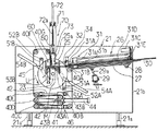
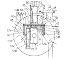
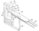
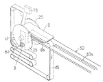
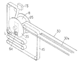
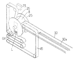
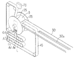
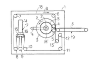
図1ないし図14は本発明に係わる巻鉄心製造装置の構成例を示したもので、図1はその全体的な構成を示す正面図、図2は図1の要部の拡大正面図、図3は図1の要部を示す斜視図、図4ないし図14は本発明に係わる巻鉄心製造装置の動作を順を追って示した斜視図である。
【0050】
図1において21は板状に形成されて垂直に起立された状態で配置された巻鉄心製造装置の主フレームで、主フレーム21はその下部に取り付けられた脚部21a,21aを介して図示しない設置ベース上に固定される。主フレーム21の先端部21a寄りの位置には主軸23がその中心軸線をフレーム21の板面と直交させた状態で、かつ水平方向に向けた状態で回転自在に支持され、主軸23に巻枠Mが取り付けられている。巻枠Mは、横断面の輪郭がほぼ矩形状(矩形の各角部に丸みをつけた形状)を呈するように形成されていて、その中心軸線を主軸23の中心軸線に一致させた状態で取り付けられている。図示してないが、主フレーム21の裏面には、電動機により減速機を介して主軸23を回転駆動する巻枠駆動装置が設けられ、この巻枠駆動装置により巻枠Mが回転駆動される。
【0051】
図4に見られるように、主軸23には、巻枠Mを軸線方向の両端側から挟むように配置された1対の面板25,25が取り付けられている。1対の面板25,25の内、主フレーム21と反対側に配置された面板25は、取り外すことができるようになっていて、この面板25を外した状態で巻枠Mの着脱を行うことができるようになっている。面板25,25には互いに整合するコの字形の切欠き部25a,25aが形成されている。図7に見られるように、各切欠き部25aは、面板25の半径方向と平行な方向に伸びる対辺25a1,25a1と、面板25の半径方向に対して直角な方向に伸びる底辺部25a2とを有していて、巻枠Mはその一方の短辺部を切欠き部25aの底辺部25a2に沿わせた状態で取り付けられる。切欠き部25aの底辺部25a2に沿う巻枠Mの一方の短辺部に巻鉄心を構成する積層体ブロックのラップ部が配置される。
【0052】
主フレーム21にはまた、積層体ブロック供給装置26が取り付けられている。積層体ブロック供給装置26は、主フレーム21の後端部21b側から巻枠M側に向って長く延びる可動フレーム27を備えている。可動フレーム27は、その後端部(巻枠Mと反対側に位置する端部)側に設けられた軸28により主フレーム21に回動自在に支持されている。可動フレーム27の下部には主フレーム21に回動自在に支持されたジャッキ29のラム29aが連結され、ジャッキ29により可動フレーム27が回動させられて、該可動フレーム27の先端部の高さが調整されるようになっている。
【0053】
可動フレーム27には、該可動フレームの長手方向に延びるガイド板30と、積層体ブロック送給機構31とが取り付けられている。ガイド板30は巻枠M側に送給される積層体ブロックBを載せて支えるために設けられたもので、その先端が面板25,25の間を通して巻枠Mの近傍に至るように設けられている。図4ないし図14に見られるように、ガイド板30の幅方向の中央部には、その長手方向に延びるスリット30aが形成されている。
【0054】
積層体ブロック送給機構31は、ガイド板30の上方に配置されてガイド板30の長手方向に移動自在に支持された可動ブロック31aに取り付けられた上部クランプ31Aと、ガイド板30の下方に配置されて可動ブロック31aと同じ方向に変位し得るように支持された可動ブロック31bに取り付けられた下部クランプ31Bと、モータ31Cと、ガイド板の長手方向に延びるように設けられて可動ブロック31aに固定されたナットに螺合されたボールネジ31Dとを備えている。
【0055】
可動ブロック31a及び可動ブロック31bは、それぞれが支持した上部クランプ31A及び下部クランプ31Bを互いに連動して変位させるように、図示しない手段により連結されている。
【0056】
モータ31Cの出力軸はチェーンスプロケット機構等からなる動力伝達機構31Eを介してボールネジ31Dに結合され、モータ31Cによりボールネジ31Dが回転駆動されて、可動ブロック31a及び31bとともに上部クランプ31A及び下部クランプ31Bがガイド板30の長手方向に往復移動させられる。
【0057】
上部クランプ31A及び下部クランプ31Bは、ガイド板30のスリット30aを通して上下に相対するクランプ部材と、該クランプ部材を駆動する流体圧シリンダとを備えている。積層体ブロックBを送給する際には、上部クランプ31Aのクランプ部材をガイド板30の上に供給された積層体ブロックBの上面に当接させ、下部クランプ31Bのクランプ部材をスリット30aを通して積層体ブロックBの下面に当接させることによりガイド板31D上の積層体ブロックBをクランプする。この状態で、モータ31Cを駆動してボールネジ31Dを回転させることにより、上部クランプ31A及び下部クランプ31Bを変位させて、積層体ブロックBを、ガイド板30の巻枠側の端部から順次巻枠M側に送り出して送給する。この例では、ガイド板30の巻枠側の端部が、積層体ブロックの送出部となっていて、可動フレーム27と、ガイド板30と、積層体ブロック送給機構31とにより、積層体ブロック供給装置26が構成され、ジャッキ29により積層体ブロック送出位置調整機構が構成されている。
【0058】
可動フレーム27の先端部には、アーム32が回動自在に支持され、該アームの先端部には、巻枠Mに巻回される積層体ブロックBに摩擦接触して該積層体ブロックBに摩擦抵抗を与える摩擦付与部材33(図2参照)が回動可能に取り付けられている。摩擦付与部材33は,所定の質量を有する板(錘)からなっている。アーム32を駆動するためにシリンダ34が設けられ、該シリンダ34を駆動することにより、摩擦付与部材33を、面板25,25の間で巻枠上の積層体ブロックに当接する位置と、該積層体ブロックから離れた状態になる退避位置とに変位させることができるようになっている。
【0059】
主フレーム21にはまた、供給装置26の先端部付近の下方に、上下に間隔をあけて配置された第1及び第2のガイドローラ40A及び40Bと、主軸23の中心軸線を含む垂直面に対して第2のガイドローラ40Bと対称に配置された第3のガイドローラ40Cと、第3のガイドローラ40Cの真上に並べて配置された第4及び第5のガイドローラ40D及び40Eと、第5のガイドローラ40Eの上方に位置させて、かつ面板25,25´よりも高い位置に配置された第6のガイドローラ40Fと、第6のガイドローラ40Fと同じ高さの位置に位置させた状態で巻枠Mの上方に配置された第7のガイドローラ40Gとが取り付けられている。第3ないし第5のガイドローラ40Cないし40Eは、狭い間隔をもって上下方向に並ぶように配置され、これらのガイドローラの中心軸線を含む垂直面と第1及び第2のガイドローラ40A及び40Bの中心軸線を含む垂直面との間に位置させた状態でスライダ41が配置されている。スライダ41は主フレーム21に固定された平行なガイド棒42,42に沿って水平方向にスライドし得るように支持されている。スライダ41には、第3及び第4のガイドローラ40C及び40Dの間の隙間に相応する位置に配置された第1のテンションローラ43Aと、第4のガイドローラ40Dと第5のガイドローラ40Eとの間の隙間に相応する位置に配置された第2のテンションローラ43Bとが支持されている。スライダ41には、主フレーム21に取り付けられたエアシリンダ44のピストンロッドが連結され、シリンダ44によりスライダ41が第3ないし第5のガイドローラ40Cないし40Eから離れる方向に付勢されるようになっている。
【0060】
第1及び第2のガイドローラ40A及び40Bと、第3のガイドローラ40Cと第1のテンションローラ43Aと、第4のガイドローラ40Dと、第2のテンションローラ42Bと、第5のガイドローラ40Eと、第6及び第7のガイドローラ40F及び40Gと、巻枠Mの外周とにループ状に形成された無端ベルト(エンドレスベルト)45が掛け渡されている。
【0061】
無端ベルト45は、巻枠Mをそのループの外側に位置させた状態でその一部が巻枠Mの外周の大部分に沿うように設けられている。図示の例では、第3ないし第5のガイドローラ40Cないし40Eとスライダ41と第1及び第2のテンションローラ43A及び43Bとシリンダ44とにより、張力付与装置(アキュムレータ)46が構成され、この張力付与装置により無端ベルト45に緊張力が与えられて、該無端ベルトが巻枠Mまたは該巻枠に巻回される積層体ブロックBの外周に密接した状態に保持されるようになっている。本明細書では、無端ベルト45の巻枠Mの外周に沿う部分の軌道R(図2参照)を無端ベルトの周回軌道と呼ぶ。
【0062】
図4ないし図14に見られるように、無端ベルト45は、巻枠Mに巻回される積層体ブロックBの幅寸法よりも小さい幅寸法を有するように形成されていて、巻枠M及び該巻枠Mに巻回される積層体ブロックの幅方向の中央部に沿うように配置されている。従って、無端ベルト45が巻枠Mの外周に巻回される積層体ブロックBの外周に接触した状態にあるときに、該積層体ブロックの幅方向の両端部には無端ベルトに接触しない部分が残される。
【0063】
主軸23の両側にはくの字形に形成された第1のしごきローラ支持アーム51A及び第2のしごきローラ支持アーム51Bが配置されている。第1のしごきローラ支持アーム51Aは、積層体ブロック供給装置26側に設けられて、ピン52Aを介して主フレーム21に回動自在に支持されている。また第2のしごきローラ支持アーム51Bは積層体ブロック供給装置と反対側に配置されて、ピン52Bを介して主フレーム21に回動自在に支持されている。
【0064】
第1のしごきローラ支持アーム51A及び第2のしごきローラ支持アーム51Bはそれぞれの先端が面板25,25の間を通して巻枠Mに接近したり該巻枠Mから離れたりするように設けられていて、それぞれの先端に取り付けられた第1及び第2のしごきローラ53A及び53Bが無端ベルト45に接触させられている。
【0065】
主フレーム21には、第1及び第2のしごきローラ支持アーム51A及び51Bを付勢する付勢手段としての第1及び第2のエアシリンダ54A及び54Bが回動自在に支持され、これらのエアシリンダ54A及び54Bのピストンロッドが第1のしごきローラ支持アーム51Aの中間部及び第2のしごきローラ支持アーム51Bの中間部にそれぞれピンを介して連結されている。第1及び第2のエアシリンダ54A及び54Bにより第1のしごきローラ支持アーム51A及び第2のしごきローラ支持アーム51Bが巻枠M側に付勢されるようになっている。
【0066】
図示の巻鉄心製造装置では、供給装置26から巻枠M上に積層体ブロックBを供給する際に、図1に示すように巻枠Mの長辺部を垂直方向に沿わせ、該巻枠Mの一方の短辺部を上方に向けた状態にして、巻枠Mを停止させる。このときの巻枠Mの停止位置を巻枠の積層体ブロック受入れ位置と呼ぶことにする。
【0067】
図示の例では、巻枠Mが積層体ブロック受入れ位置に停止したときに、無端ベルト45の巻枠Mから第7のガイドローラ40Gに向けて立上る部分が垂直方向に沿うように、第7のガイドローラ40Gの位置が設定されている。また第1のしごきローラ53Aは、巻枠Mの長辺部が垂直方向に沿うように配置された状態にあるときに、該巻枠Mの積層体ブロック供給装置26側の長辺部の上端部付近で無端ベルト45に接触するように設けられる。更に第2のしごきローラ53Bは、巻枠Mの長辺部が垂直方向に沿うように配置されたときに、巻枠Mの積層体ブロック供給装置26と反対側の長辺部の下端部付近で無端ベルト45に接触するように設けられる。
【0068】
図示の例では、巻枠Mが回転する過程で、第1のしごきローラ53Aが巻枠Mの1つの角部に対向して無端ベルトに接触した際に、第2のしごきローラ53Bが、第1のしごきローラに対向する角部と対角位置にある他の角部に対向して無端ベルトに接触し、図1及び図2に示すように巻枠Mが積層体ブロック導入位置にあるときには、第1のしごきローラ53A及び第2のしごきローラ53Bが巻枠Mの異なる長辺部の端部寄りの位置で無端ベルトに接触するように、第1及び第2のしごきローラが設けられている。
【0069】
図示の例では、第7のガイドローラ40Gと第1のしごきローラ53Aと、第2のしごきローラ53Bとにより、無端ベルト45の巻枠Mの外周に沿う周回軌道Rが定められている。この周回軌道Rは、第7のガイドローラ40Gから巻枠M側に下降する無端ベルト45が巻枠Mまたは該巻枠に巻かれた積層体ブロックBに接する位置を始点P(図2参照)とし、無端ベルト45が第1のしごきローラ53Aと巻枠Mまたは巻枠Mに巻回された積層体ブロックBとの間から離脱する位置を終点Qとする軌道である。無端ベルト45は、シリンダ54Aにより付勢されて周回軌道Rの終点Q付近で該無端ベルトに接触する第1のしごきローラ53Aの働きと、シリンダ54Bにより付勢されて周回軌道Rの始点Pと終点Qとの間の中間部付近で該無端ベルトに接触する第2のしごきローラ53Bの働きとにより、常時巻枠M側に押し付けられた状態で走行する。
【0070】
巻枠Mが回転させられると、第1のしごきローラ53Aと無端ベルト45との接点と主軸23との間の距離、及び第2のしごきローラ53Bと無端ベルト45との接点と主軸23との間の距離が変化し、これらの距離の変化に追従して第1及び第2のしごきローラ53A及び53Bの位置が変化する。このように巻枠Mの回転に追従して第1及び第2のしごきローラの位置が変化することにより、巻枠Mの円滑な回転が許容される。
【0071】
無端ベルト45の巻枠Mに沿う周回軌道の始点Pと終点Qとの間に、積層体ブロック導入部(無端ベルトが開いた部分)Gが形成され、積層体ブロック供給装置26から導入部Gを通して巻枠M側に積層体ブロックBが供給される。
【0072】
巻枠Mの両側に設けられた面板25,25には、巻枠M上の積層体ブロックの一端側の端部(ラップ部を構成する端部)をクランプする1対のラップクランプ装置60,60が取り付けられている。図2及び図3に示したように、各ラップクランプ装置60は、面板25の切欠き部25aの底辺部25a2及び巻枠Mの一方の短辺部に長手方向を沿わせた状態で面板25の外側に配置された矩形状の可動板61を備えている。可動板61は、垂直方向に向くように配置されて面板25の外面に固定された1対のガイドレール62,62により主軸23の径方向に沿う第1の方向(図示の例では上下方向)に移動自在に支持されたスライダ63,63の上端に固定されている。
【0073】
可動板61の下面の中央部には、クランプ板64がガイド機構65を介して主軸23の軸線方向に沿う第2の方向に移動自在に支持されている。ガイド機構65は、ガイドレールと該ガイドレールにスライド自在に保持されたスライダとを備えた公知のものである。
【0074】
クランプ板64は、積層体ブロックの一端側の端部をクランプするために必要な機械的強度を確保するために必要最小限の厚さを有する板からなっていて、図4ないし図14に見られるように、クランプ板64には、巻枠M側に向かうに従って該クランプ板の厚みを薄くする向きのテーパがつけられている。
【0075】
クランプ板64は、その板面が巻枠Mの一方の短辺部に沿うように設けられていて、可動板61の変位に伴って主軸の径方向に沿う第1の方向に沿って移動し、ガイド機構65の働きにより主軸23の軸線方向に沿う第2の方向に変位する。このクランプ板64は、第2の方向(主軸の軸線方向)に沿って巻枠Mの一方の短辺部の外周面に対向する位置まで変位させられた状態で第1の方向(主軸の径方向)に沿って巻枠側に変位させられたときに巻枠M上の積層体ブロックBの一端側の端部に当接して該一端側の端部を巻枠Mに対してクランプし、第2の方向(主軸の軸線方向)に沿って巻枠から離れる側に移動させられたときに一端側の端部のクランプを解除する。
【0076】
クランプ板64を主軸の径方向に沿う第1の方向に沿って変位させるため、第1のラップクランプ駆動用エアシリンダ66のピストンロッド66aが可動板61に連結されている。またクランプ板64を主軸の軸線方向に沿う第2の方向に沿って変位させるために、可動板61の下面に固定された第2のラップクランプ駆動用エアシリンダ67のピストンロッド67aが連結部材68を介してクランプ板64に連結されている(図3参照)。可動板61とガイドレール62,62とスライダ63,63と第1のラップクランプ駆動用エアシリンダ66とにより、クランプ板64を第1の方向に沿って移動させる第1のクランプ板駆動機構が構成されている。またガイド機構65と第2のラップクランプ駆動用エアシリンダ67とにより、クランプ板64を第2の方向に沿って移動させる第2のクランプ板駆動機構が構成され、クランプ板64と第1及び第2のクランプ板駆動機構とにより、ラップクランプ装置60が構成されている。各ラップクランプ装置60は面板25に取付けられているため、主軸23が回転駆動されたときに巻枠Mとともに回転して、巻枠M上の積層体ブロックをクランプしたりアンクランプしたりする。
【0077】
積層体ブロック導入部Gにはまた、積層体ブロック導入部に供給された積層体ブロックの一端側の端部を巻枠側に押え付けるラップ押え装置70が設けられている。このラップ押え装置70は、積層体ブロック導入部Gに相応する位置で主フレーム21に固定されたシリンダ取付け板71にピストンロッド72aを下方に向けた状態で取り付けられたエアシリンダ72と、該エアシリンダ72のピストンロッド72aの下端に固定された押え部材73とからなっている。エアシリンダ72は、そのピストンロッド72aを主軸23の中心軸線を含む垂直面上で巻枠Mの外周面の幅方向の中央部に向けた状態で設けられ、押え部材73は、エアシリンダ72により駆動されて、積層体ブロック導入部Gにある積層体ブロックBのラップ部に当接して該ラップ部を巻枠M側に押え付ける押え位置と該ラップ部から離れて巻枠Mの回転を許容する状態になる退避位置との間を主軸23の軸線方向と直角な方向に沿って変位させられる。この例では、エアシリンダ71により、押え部材73を押え位置と退避位置とに変位させる押え部材駆動機構が構成されている。
【0078】
また図示の例では、第7のガイドローラ40Gを支持する軸に無端ベルト45の幅方向の両側で巻枠M上の積層体ブロックBに接触する1対の半月形のバネ80,80が設けられている。
【0079】
図示の例では、主軸23と、主軸に取り付けられた巻枠Mと、主軸を回転させて巻枠Mを駆動する巻枠駆動装置と、ガイドローラ40A〜40Gなどによりガイドされた無端ベルト45と、ラップクランプ装置60と、ラップ押え装置70とにより、巻鉄心巻回装置が構成されている。
【0080】
巻鉄心の製造を自動的に行わせるため、巻枠駆動装置と積層体ブロック供給装置26とラップ押え装置70の押え部材駆動機構とラップクランプ装置60の第1及び第2のクランプ板駆動機構と積層体ブロック送出位置調整機構とを制御する制御装置を設けるのが好ましい。この制御装置は、巻枠Mの回転角度を検出するセンサ、積層体ブロックの一端が巻枠Mの一方の短辺上の所定位置に到達したことを検出するセンサ、及び各部の動作位置を検出する位置センサ等の各種のセンサと、これらのセンサの検出出力を入力として各部をシーケンス制御するマイクロコンピュータとにより構成することができる。
【0081】
この制御装置は、巻枠Mの一方の短辺部を積層体ブロック導入部Gに位置させた状態で積層体ブロック導入部Gを通して巻枠Mの一方の短辺部の位置に積層体ブロックBの一端側の端部Ba を供給する積層体ブロック供給動作と、巻枠Mの一方の短辺部の位置に供給された積層体ブロックBの一端側の端部Ba をラップ押え装置70の押え部材73により巻枠に対して押え付けるラップ押え動作と、押え部材73により押え付けられた積層体ブロックの一端側の端部Ba にラップクランプ装置60のクランプ板64を当接させて該一端側の端部をクランプする積層体端部クランプ動作と、押え部材73を退避位置に変位させて巻枠Mの回転が許容される状態にするラップ押え退避動作と、巻枠を回転させて一端側の端部がクランプされた積層体ブロックBを無端ベルト45の内側に巻き込んでその一端側の端部Ba に他端側の端部Bb を重ね合わせることによりラップ部Lを形成した後、該ラップ部Lを無端ベルト45の内側に位置させた状態で停止させる積層体ブロック巻回動作と、積層体ブロックBのラップ部Lを構成する一端側の端部Ba と他端側の端部Bb との間に挟み込まれた状態にあるクランプ板64を第2の方向に沿って巻枠から離れる側に変位させてラップ部Lから離脱させるクランプ板離脱動作と、ラップ部Lから離脱したクランプ板64を該ラップ部の外周側に当接して該ラップ部を巻枠に対してクランプする位置まで変位させるラップ部クランプ動作と、ラップ部Lを積層体ブロック導入部Gに位置させるまで巻枠Mを回転させて停止させる巻枠復帰動作と、巻枠に巻回された積層体ブロックの外径寸法の増大に合わせて新たに供給される積層体ブロックの送り出し位置を変化させるように前記積層体ブロック送出位置調整機構を駆動する動作とを必要な数の積層体ブロックが巻回されるまで繰り返すように構成される。
【0082】
上記制御装置を実現するためにマイクロコンピュータにより実行させるプログラムのアルゴリズムの一例を図15に示した。このアルゴリズムによる場合の巻鉄心巻回動作を説明すると下記の通りである。
【0083】
プログラムが開始されると、先ず所定枚数積層された非晶質磁性合金薄帯を図示しないシヤーにより所定の長さに切断して単位積層体を形成し、この単位積層体を段積みすることにより、図16に示したような構造の積層体ブロックBを形成する(図15のステップ1)。次いでこの積層体ブロックBを積層体ブロック供給装置26の受取り位置に搬送する(ステップ2)。ステップ1とステップ2とを繰り返すことにより、巻鉄心を構成するために必要な数の積層体ブロックを順次製作して、一連の積層体ブロックを積層体ブロック供給装置26の受取り位置に供給する。
【0084】
図15のステップ3では、図4に示すように、積層体ブロック供給装置26のガイド板30上の待機位置に積層体ブロックBを搬送する。次いでステップ4で上部クランプ31A及び下部クランプ31Bを待機している積層体ブロックの位置(受取り位置)まで移動させ、ステップ5で該積層体ブロックの先端部付近をクランプする。巻鉄心巻回装置側で新たな積層体ブロックを受入れる条件が成立したことが検出されたときにステップ6を行って、積層体ブロックBをクランプしたクランプ31A及び31Bを巻枠M側に移動させ、図5に示すように、積層体ブロックBの一端側の端部Ba を積層体ブロック導入部Gを通して積層体ブロック受入れ位置で停止している巻枠Mの一方の短辺上に挿入する。次いでステップ7でクランプ31A及び31Bによる積層体ブロックBのクランプを解除する。
【0085】
積層体ブロックBの一端を巻枠Mの一方の短辺上に供給した後、ステップ8を実行して、図6に示すようにラップ押え装置70の押え部材73を押え位置まで下降させて、積層体ブロックBの一端の端部Ba を巻枠Mの短辺に対して加圧する。次いでステップ9を行って、図7に示すようにラップクランプ装置60,60のクランプ板64,64を主軸23の軸線方向の外側に平行移動させることにより、巻枠Mの外側に離脱させる。次いでステップ10において、図8の矢印A1 に示すようにラップクランプのクランプ板64,64を主軸の径方向の外側に変位(上昇)させた後、ステップ11において図8の矢印A2 に示すようにクランプ板64,64を主軸の軸線方向の内側に平行移動させ、更にステップ12において図8の矢印A3 のようにクランプ板64,64を主軸の径方向の内側に変位(下降)させて、積層体ブロックBの一端側の端部Ba に当接させることにより、端部Ba をクランプする。
【0086】
クランプ板64,64により積層体ブロックBの一端側の積層端面Ba をクランプした後、ステップ13において図9に示すようにラップ押え装置の押え部材73を上方の退避位置まで移動させてラップ押え装置を開放する。
【0087】
ラップ押え装置を開放した後、図示しない巻枠駆動装置により主軸23を回転させて巻枠Mを図示の矢印Uの方向に回転させる。これにより無端ベルト45を矢印U方向に走行させ、図10に示すように巻枠Mに一端側の端部Ba が固定された積層体ブロックBを無端ベルト45の内側に巻き込んで巻枠Mの回りに巻回する。このとき積層体ブロックBに摩擦付与部材33が接触して、該積層体ブロックに適度の張力を与え、また無端ベルト45の幅方向の両側に配置されたバネ80,80が積層体ブロック導入部Gの始点P付近で積層体ブロックBに接触して、該積層体ブロックBを巻枠M側に押圧するため、無端ベルト45の内側への積層体ブロックBの巻き込みは円滑に行われる。
【0088】
図10は巻枠Mを図9の状態から180度回転(1/2回転)させた状態を示している。図11に示したように、図9の状態から巻枠Mを1+α(0<α<1)回転させたところで、巻枠Mを停止させる。図11はα=0.5として、図9の状態から巻枠を1.5回転(540度回転)させたところで停止させた状態を示している。図11の状態では、無端ベルト45の内側に巻き込まれた積層体ブロックBの一端側の端部Ba の上にクランプ板64を介して他端側の端部Bb が重ね合わされてラップ部Lが形成された状態にある。
【0089】
巻枠Mを1.5回転させて停止させた後、ステップ15を行い、図12に示すようにクランプ板64,64を主軸の軸線方向に沿って外側に平行移動させてラップ部Lから離脱させる。ステップ15においてクランプ板64,64を離脱させた後、ステップ16を行ってクランプ板64,64を図13に矢印A1 ´で示したように主軸の径方向の外側に移動させる。次いでステップ17を行ってクランプ板64,64を図13に矢印A2 ´で示したように主軸の軸線方向に沿って内側に平行移動させた後、ステップ18を行ってクランプ板64,64を図13に矢印A3 ´で示したように主軸の径方向の内側に移動させる。これによりクランプ板64,64を図13に示すように積層体ブロックBのラップ部Lに当接するクランプ位置に到達させてラップ部Lをクランプする。その後ステップ19で巻枠Mを1−α回転(図示の例では1−α=0.5回転)させて図14に示すように巻枠Mを積層体ブロック受入れ位置に戻し、巻枠Mの一方の短辺部を積層体ブロック導入部Gに位置させる。
【0090】
巻枠Mの回りに積層体ブロックを巻回していくと、巻回した積層体ブロックの数の増大に伴って巻枠の回りに形成される積層体ブロック巻回体の外径寸法が大きくなっていくため、この外径寸法の増大に合わせて新たな積層体ブロックBを巻枠側に送り出す位置を変化させる必要がある。そのため、図1に示した例では、積層体ブロック供給装置26にジャッキ29からなる積層体ブロック送出位置調整機構を設けて、該調整機構により可動フレーム27の傾きを調節して、ガイド板30の先端(積層体ブロックの送出部)の高さを変化させることにより、積層体ブロック巻回体の外径寸法の増大に合わせて、供給装置26からの積層体ブロックの送り出し位置を上昇させるようにしている(ステップ20)。
【0091】
上記の例で示したように、巻枠Mの両側に面板25,25を配置して、巻枠Mに巻かれる積層体ブロックの幅方向の位置を規制するようにすると、積層体ブロックの位置を揃えて、積層面の凹凸が少ない巻鉄心を得ることができるが、これらの面板は省略してもよい。
【0092】
面板25,25を省力する場合には、適宜の支持手段を主軸23に取り付けて、該支持手段を介してラップクランプ装置を支持する。
【0093】
また上記の例のように積層体ブロックBに摩擦接触する摩擦付与部材(錘)33を設けておくと、積層体ブロックBに適当な張力を与えて、該積層体ブロックの巻き込みを円滑に行わせることかできるが、この摩擦付与部材は省略することもできる。
【0094】
更に、上記のようにバネ80,80を設けておくと、積層体ブロックBを巻枠Mに沿わせることができるため、積層体ブロックの巻き込みを容易にすることができるが、このバネも省略することができる。
【0095】
上記の例では、各積層体ブロックを複数の単位積層体により構成しているが、本発明において、「積層体ブロック」は、巻枠に一度に巻回される非晶質磁性合金薄帯の積層体を意味し、各積層体ブロックを構成する単位積層体の数は任意である。即ち、各積層体ブロックは少くとも1つの単位積層体からなっていればよく、1つの単位積層体を1つの積層体ブロックとして該積層体ブロックを順次巻枠に巻回して巻鉄心を形成する場合にも本発明を適用することができる。
【0096】
【発明の効果】
以上のように、本発明によれば、主軸とともに回転するように設けられてラップ部を構成する積層体ブロックの端部を巻枠に対してクランプするラップクランプ装置を設けて、積層体ブロックを無端ベルトの内側に巻き込んで巻回する際に積層体ブロックの端部が巻枠に対して動くことがないようにしたため、ラップ部の位置がずれるのを防ぐことができ、ラップ流れが生じるのを防ぐことができる。
【0097】
更に本発明によれば、積層体ブロックの端部を巻枠に対してクランプするようにしたので、積層体ブロックが無端ベルトから開放された状態になったときにラップ部が開くのを防ぐことができ、また積層体ブロック導入部に供給された積層体ブロックの一端側の端部を巻枠側に押え付けるラップ押え装置を設けたので、既に巻回されている積層体ブロックのラップ部を開かせることなく、新たに積層体ブロック導入部に供給された積層体ブロックの一端側の端部をクランプすることができる。従って、巻回された積層体ブロックのラップ部を開かせることなく全ての積層体ブロックの巻回作業を円滑に進めて、高品質の巻鉄心を得ることができる。
【図面の簡単な説明】
【図1】本発明の実施例の全体的な構成を示す正面図である。
【図2】図1の要部を示す拡大正面図である。
【図3】図1の要部を示す斜視図である。
【図4】本発明に係わる巻鉄心製造装置において新たな積層体ブロックを積層体ブロック導入部に供給する際の状態を示した斜視図である。
【図5】本発明に係わる巻鉄心製造装置において積層体ブロック導入部に積層体ブロックが供給された状態を示した斜視図である。
【図6】本発明に係わる巻鉄心製造装置において積層体ブロック導入部に供給された積層体ブロックをラップ押え装置の押え部材により押え付けた状態を示した斜視図である。
【図7】本発明に係わる巻鉄心製造装置において積層体ブロック導入部に供給された積層体ブロックの端部をラップ押え装置の押え部材により押え付けた状態を示した斜視図である。
【図8】本発明に係わる巻鉄心製造装置において積層体ブロック導入部に供給された積層体ブロックの端部をラップクランプ装置によりクランプした状態を示した斜視図である。
【図9】本発明に係わる巻鉄心製造装置において積層体ブロック導入部に供給された積層体ブロックの端部をラップクランプ装置によりクランプした後押え部材を退避させた状態を示した斜視図である。
【図10】本発明に係わる巻鉄心製造装置において積層体ブロック導入部に供給された積層体ブロックをクランプした後巻枠を1/2度回転させて積層体ブロックを無端ベルトの内側に巻き込んだ状態を示した斜視図である。
【図11】本発明に係わる巻鉄心製造装置において積層体ブロック導入部に供給された積層体ブロックをクランプした後巻枠を1.5回転させることにより積層体ブロックを巻回してその両端を重ね合わせた状態を示した斜視図である。
【図12】本発明に係わる巻鉄心製造装置において巻回された積層体ブロックの両端のラップ部からラップクランプ装置のクランプ板を離脱させた状態を示した斜視図である。
【図13】本発明に係わる巻鉄心製造装置において巻回された積層体ブロックの両端のラップ部からクランプ板を離脱させた後、ラップ部をクランプした状態を示した斜視図である。
【図14】本発明に係わる巻鉄心製造装置において積層体ブロックのラップ部をクランプした後巻枠を1/2回転させて停止させた状態を示した斜視図である。
【図15】本発明に係わる巻鉄心製造装置に設ける制御装置の制御アルゴリズムを示したフローチャートである。
【図16】本発明で用いる積層体ブロックの1つを示した斜視図である。
【図17】本発明の巻鉄心製造装置により製造される巻鉄心の正面図である。
【図18】従来の巻鉄心製造装置の正面図である。
【図19】(A)はラップ部が正常に分布している巻鉄心を示した正面図、(B)はラップ流れが生じた巻鉄心を示した正面図である。
【符号の説明】
21 主フレーム
23 主軸
25 面板
25 切欠き部
26 積層体ブロック供給装置
27 可動フレーム
30 ガイド板
31A 上部クランプ
31B 下部クランプ
33 摩擦付与部材
40A〜40G ガイドローラ
43A,43B テンションローラ
45 無端ベルト
51A 第1のしごきローラ支持アーム
51B 第2のしごきローラ支持アーム
53A 第1のしごきローラ
53B 第2のしごきローラ
54A 第1のエアシリンダ
54B 第2のエアシリンダ
60 ラップクランプ装置
61 可動板
64 クランプ板
65 ガイド機構
66 第1のラップクランプ駆動用エアシリンダ
67 第2のラップクランプ駆動用エアシリンダ
70 ラップ押え装置
72 エアシリンダ
80 バネ[0001]
BACKGROUND OF THE INVENTION
The present invention relates to a wound core manufacturing apparatus that manufactures a wound core from an amorphous magnetic alloy ribbon.
[0002]
[Prior art]
Recently, amorphous magnetic alloys have attracted attention as a low-loss magnetic material. When an iron core for an electric device such as a transformer is formed using this material, a low-loss electric device can be obtained. it can. An amorphous magnetic alloy is provided in the form of a ribbon (thin strip) having a very thin thickness (about 25 μm), and its handling is troublesome. In the case of constructing, it is advantageous to adopt a wound core structure.
[0003]
As a wound iron core using a silicon steel strip, a one-turn cut type iron core is often used. When manufacturing a one-turn cut type wound core, steel strips cut to have a length slightly longer than one turn are sequentially wound around a circular reel, and the steel strip of each turn A method is employed in which a circular wound core with both ends overlapped and joined stepwise is manufactured, and then this circular wound core is shaped into a rectangular shape and annealed.
[0004]
However, as described above, since the amorphous magnetic alloy is very thin and is difficult to handle, a one-turn cut type structure was adopted when forming a wound core with an amorphous magnetic alloy ribbon. Then, an iron core cannot be manufactured efficiently.
[0005]
In view of this, a method of forming a wound core using a unit laminated body obtained by laminating several or tens of amorphous magnetic alloy ribbons is employed. In this method, a large number of unit laminated bodies having lengths that are sequentially increased by 2πt (t is the thickness of the unit laminated body) are formed, and a single unit laminated body or n unit laminated bodies (n is 2). A laminate block is formed by laminating each position in the longitudinal direction in order from the shortest one by the above integer). By winding m pieces (m is an integer of 1 or more) of laminate blocks obtained in this way around a rectangular winding frame in order from the shortest one, the both ends of each laminate block are overlapped and joined. A rectangular wound core is formed.
[0006]
FIG. 16 shows, as an example, the configuration of the first laminated body block B1 when the number of unit laminated bodies n of one laminated body block is 3, and in this example, 2πt (the circumference for each turn) The laminated body block B1 is constituted by laminating the unit laminated bodies U1 to U3 whose lengths are increased by increments) by shifting the positions in the longitudinal direction by a dimension ΔX. Similarly, three unit laminated bodies U4, U5,... Are sequentially laminated to form second and subsequent laminated body blocks B2, B3,. The end portion Ba on the one end side and the end portion Bb on the other end side in the longitudinal direction of each laminate block are formed in a step shape. In some cases, the number of unit laminates may be different for each laminate block, and a single unit laminate may be used as a laminate block.
[0007]
FIG. 17 shows the structure of a wound iron core constructed by winding the laminated body block constructed as described above around a winding frame M. In this example, the number m of laminated body blocks is 3. The winding frame M is formed so that the outline of its transverse cross section (cross section orthogonal to the central axis) has a substantially rectangular shape. On the winding frame M, a laminate block B1 composed of unit laminate bodies U1 to U3, a laminate block B2 composed of unit laminate bodies U4 to U6, and a laminate block B3 composed of unit laminate bodies U7 to U9 are sequentially wound. One end side end and the other end side end of each of the unit laminated bodies that are stacked and wound are overlapped and joined on one short side of the rectangular winding frame M to form a wound core Has been. In the present specification, a portion L in which the end portion on one end side and the end portion on the other end side of each unit laminate body are overlapped and joined to each other is referred to as a lap portion.
[0008]
A steel strip S made of stainless steel or the like is wound around the outermost periphery of the wound core and the shape thereof is maintained. In this state, the whole is annealed and has yoke portions Y1 and Y2 and leg portions C1 and C2. A rectangular wound core is completed.
[0009]
For example, when a transformer for power distribution is constructed using this wound core, the steel strip S is removed, the joint formed in the yoke Y1 is opened, the reel M is removed, and then the legs C1 and Each winding is fitted to C2. After the windings are fitted to the leg portions C1 and C2, the joint portion of the yoke portion Y1 is closed, the steel strip S is wound around the outermost periphery of the wound iron core, and both ends of the steel strip are welded.
[0010]
Note that the annealed amorphous magnetic alloy is in a very fragile state, and there is a risk of debris being generated from the iron core when handling the winding, so when inserting the winding into the iron core, cover the iron core with a cover. Measures such as covering are taken.
[0011]
Conventionally, as described above, a single unit laminate or a laminate of a predetermined number of unit laminates shifted by a predetermined shift dimension ΔX is used as a block of the laminate, and the laminate block is wound around the winding frame M. Therefore, the method of manufacturing the wound core has been taken, but the process of winding the laminated body block around the wound core and joining the both ends requires manual work, resulting in poor work efficiency and high core cost. It was inevitable to become.
[0012]
As a device for manufacturing a circular wound iron core, a manufacturing device (Japanese Patent Publication No. 6-9180) as shown in FIG. 18 has been proposed. In this wound iron core manufacturing apparatus, a
[0013]
Further, a
[0014]
When the wound iron core is manufactured using the apparatus of FIG. 18, the
[0015]
[Problems to be solved by the invention]
In the wound iron core manufacturing apparatus shown in FIG. 18, since the wound iron core is formed in a circular shape, a wound iron core having a polygonal cross section, for example, a rectangular wound iron core as shown in FIG. For this, it is necessary to perform a work of forming a circular wound core into a rectangular shape before annealing, which is troublesome.
[0016]
In the wound iron core, it is desirable that the lap portions L of a series of laminated body blocks are distributed in an orderly manner within a region W having a constant width as shown in FIG.
[0017]
However, when the laminated body block B of amorphous magnetic alloy ribbon is wound around the circular winding frame M ′ by the wound iron core manufacturing apparatus shown in FIG. 18, a series of laminated body blocks are wound around the winding frame. In the process of turning, the position of the lap part of the laminated body block located on the outside shifts from the position of the lap part of the laminated body block located on the inside, so that the wrap as shown in FIG. There may be a so-called “wrap flow” state in which the region W ′ where the portion L exists is in an obliquely developed state. Even if the circular wound core in which the wrap flow is generated is shaped into a rectangular shape, it is not possible to obtain a wound core in which the wrap portion is correctly distributed in the vicinity of the center portion of one yoke portion Y1 as shown in FIG.
[0018]
In the wound iron core manufacturing apparatus shown in FIG. 18, it is also conceivable to use a polygonal shape, for example, a rectangular shape, as the winding frame M ′. In that case, in order to enable rotation of the rectangular winding frame, the gap between the
[0019]
Accordingly, in the wound iron core manufacturing apparatus of FIG. 18, when a roll having a polygonal cross-sectional shape such as a rectangle is used, the wrap portion is prevented from opening during the winding operation of the laminated body block. Therefore, it was necessary to add a manual work to manufacture the wound iron core efficiently.
[0020]
An object of the present invention is to provide a wound core manufacturing apparatus capable of efficiently manufacturing a wound core without causing a state of lap flow.
[0021]
[Means for Solving the Problems]
The present invention relates to a winding frame whose central portion is supported by a main shaft, a winding frame driving device that rotationally drives the winding frame, and a state in which the winding frame is positioned outside the loop and formed to form a loop. A unit comprising a plurality of laminated amorphous magnetic alloy ribbons and an endless belt that is guided so as to be along a circular orbit along the outer circumference of the reel and driven by the rotation of the reel. A single unit of the laminate or unit laminates of n (n is an integer of 1 or more) are laminated with their positions shifted in the longitudinal direction, and one end side and the other end side in the longitudinal direction are formed in a staircase shape. The present invention relates to a wound core manufacturing apparatus provided with a laminated body block supply device that sequentially supplies the laminated body block to the reel side as a laminated body block.
[0022]
The endless belt orbit is set so as to form a laminate block introduction portion that receives an end portion on one end side in the longitudinal direction of the laminate block supplied by the laminate block supply device between the start point and the end point thereof. Is done. In addition, the laminated body block supply device is arranged so that one end side of each laminated body block faces the outer periphery of the winding frame in a state where one end in the longitudinal direction of each laminated body block is directed to the starting point of the endless belt. Provided to supply. Laminate blocks sequentially supplied by the laminate block supply device are wound inside the endless belt, wound and stacked on a reel, and one end and the other end of each wound laminate block A wound iron core having a structure in which a lap portion is formed by superimposing the end portion of the winding on one short side portion of the winding frame is manufactured.
[0023]
In the present invention, a lap press device that presses the end of one side of the laminate block supplied to the laminate block introduction portion to the reel side, and a stack that is provided so as to rotate together with the main shaft to constitute the lap portion A lap clamp device is provided for clamping the end of the body block to the winding frame.
[0024]
As described above, if a lap clamp device that clamps the end of the laminated body block, which is provided so as to rotate with the main shaft and constitute the lap portion, is clamped against the winding frame, the laminated body block is placed inside the endless belt. Since the edge part of a laminated body block does not move with respect to a winding frame when winding in and winding, it can prevent that the position of a wrap part shifts | deviates and it can prevent that a wrap flow arises.
[0025]
In addition, if the end of the laminate block is clamped against the winding frame as described above, the lap portion does not open even when the laminate block is released from the endless belt. When the short side part and long side part of a winding frame pass the position of a laminated body block introduction part, it can prevent that a lap | wrap part opens.
[0026]
Furthermore, as described above, if a wrap presser device is provided that presses the end of one end of the laminate block supplied to the laminate block introduction part to the winding frame side, the laminate block that has already been wound is provided. The end of one end side of the laminate block newly supplied to the laminate block introducing portion can be clamped without opening the wrap portion.
[0027]
Therefore, according to the present invention, it is possible to proceed with the winding operation of a series of laminate blocks without causing the wrap portion of the wound laminate block to be opened, and without causing a positional shift of the wrap portion. It is possible to manufacture a high-quality wound core without wrap flow.
[0028]
The wrap presser device is provided so that it can be displaced in a direction perpendicular to the axial direction of the main shaft at the laminated body block introducing portion, and is in contact with one end of the laminated body block at the laminated body block introducing portion. A presser provided so as to be displaceable between a presser position where the end on the one end side is pressed against the reel side and a retracted position where the reel is allowed to rotate away from the end on the one end side. It can be constituted by a member and a presser member driving mechanism for displacing the presser member to a presser position and a retracted position.
[0029]
The wrap clamp device is provided so as to be movable along a first direction along the radial direction of the main shaft, and is provided so as to be movable in a second direction along the axial direction of the main shaft. In the state of being displaced to the position facing the outer peripheral surface of the reel along the direction of 2, when being displaced toward the reel along the first direction, the end of the laminated body block on the reel A clamp plate provided to abut and clamp the end against the reel, and to release the end clamp when moved to the side away from the reel along the second direction; The clamp plate can be constituted by a first clamp plate drive mechanism that displaces the clamp plate along a first direction and a second clamp plate drive mechanism that moves the clamp plate in the second direction.
[0030]
In this case, the endless belt is formed to have a width dimension smaller than the width dimension of the laminated body block, and is disposed along the center portion in the width direction of the laminated body block. It is provided so as to abut the end portion of the laminated body block that does not interfere with the endless belt when it is in the clamping position, and to abut the end portion in the width direction so as to clamp the end portion.
[0031]
In the present invention, there is also provided a laminate block feed position adjusting mechanism that changes the position of the delivery portion of the laminate block supply device in accordance with the increase in the outer diameter of the laminate block wound around the winding frame. Is preferred.
[0032]
As described above, when the clamp plate of the lap clamp device is displaced in the axial direction (second direction) of the main shaft so that it can be detached from the laminate block, the laminate block is placed inside the endless belt. A lap part is formed by overlapping the end part on one end side and the end part on the other end side of the laminated body block to form a lap part, and then the lap part is constrained by an endless belt. The wrap portion can be clamped again by once detaching the clamp plate sandwiched between the end portions of the body block from the laminated body block. If the wrap portion is clamped in this way, the wrap portion can be prevented from opening when the wrap portion is released from the endless belt.
[0033]
In addition, as described above, a wrap press device is provided that presses the end of one end of the laminate block supplied to the laminate block introduction portion to the reel side, and the clamp plate of the wrap clamp device is attached in the axial direction of the spindle ( When the new laminate block is supplied to the laminate block introducing portion, the end of the laminate block is moved when the laminate block is disengaged in the second direction). Since it is possible to clamp the end of one end of the new laminate block by releasing the clamp plate in a state of being pressed against the reel side, without opening the wrap of the already laminated laminate block, The edge part of the one end side of the newly supplied laminated body block can be clamped with a lap clamp device.
[0034]
It is preferable to arrange a pair of face plates provided at both ends in the axial direction of the winding frame so as to rotate together with the winding frame and restrict the position in the width direction of the laminated body block on the winding frame. .
[0035]
By providing a pair of face plates in this way, the position of the laminated body block wound around the winding frame can be aligned in the width direction, so that a series of laminated body blocks can be wound in an orderly manner. It is possible to obtain a high-quality wound iron core with no body block displacement.
[0036]
In the present invention, the reel driving device, the laminate block supply device, the presser member drive mechanism of the wrap press device, the first and second clamp plate drive mechanisms of the lap clamp device, and the stack block feed position adjustment It is preferable to further provide a control device for controlling the mechanism.
[0037]
This control device provides a laminate block supply operation for supplying the end of one end side of the laminate block to a position facing the outer periphery of the reel through the laminate block introducing portion, and the position of one short side of the reel. The pressing operation of pressing the end of one side of the supplied laminated body block against the winding frame by the pressing member of the lap pressing device, and wrapping to the end of one side of the laminated body block pressed by the pressing member Laminate end clamp operation that clamps the end of one end by abutting the clamp plate of the clamp device, and a wrap presser that displaces the presser member to the retracted position and allows the reel to rotate. With the retracting operation, the winding block is rotated and the laminated body block whose one end is clamped is wound inside the endless belt, and the other end is overlapped with the one end of the laminated block. By After forming the lap portion, the laminated body block winding operation for stopping the winding frame in a state where the wrap portion is positioned between the endless belt and the winding frame, and one end side constituting the wrap portion of the laminated body block A clamp plate detachment operation for displacing the clamp plate in a state of being sandwiched between the end portion of the first end portion and the end portion on the other end side to the side away from the winding frame along the second direction and detaching from the wrap portion; A lap part clamping operation for displacing the clamp plate released from the lap part to the outer peripheral side of the lap part and displacing the wrap part to a position for clamping the wrap part with respect to the winding frame, and positioning the lap part at the laminated body block introduction part The reel returning operation of rotating the reel until the reel is stopped and the feeding position of the newly supplied laminate block is changed in accordance with the increase in the outer diameter of the laminate block wound around the reel. Laminate block The number of laminated block required and the operation of driving the position adjusting mechanism out configured to repeat until wound.
[0038]
It is preferable that a pair of the lap clamp devices is provided, and the pair of lap clamp devices are respectively disposed on both sides in the axial direction of the winding frame. In this case, the wrap presser is in contact with the laminated end portion at a position near the center in the width direction of the laminated end portion of the laminated body block in the laminated body block introduction portion so as not to interfere with the clamp plate of the lap clamp device. It is preferable to provide in.
[0039]
In the case where a pair of lap clamp devices and a pair of face plates are provided, a pair of lap clamps are provided by providing notch portions that are aligned with each other at portions where the clamp plates of the pair of face plate clamp devices are disposed. Preferably, each clamping plate of the device is displaced through the notch in the face plate.
[0040]
As described above, if a pair of wrap clamp devices are provided, the end of the laminate block can be stably clamped at both ends in the width direction, so the laminate block is wound inside the endless belt. In the process of turning, it is possible to prevent the clamp from coming off and to perform a stable operation.
[0041]
In the present invention, the first ironing roller that contacts the endless belt near the end point of the circular track and presses the endless belt against the reel side, and the endless belt near the intermediate portion between the start point and the end point of the circular track It is preferable to provide a second ironing roller that contacts the endless belt and presses the endless belt against the reel side.
[0042]
In this case, the first and second squeezing rollers are supported so that they can be displaced following the rotation of the reel, and are urged toward the reel by the urging means.
[0043]
The first and second squeezing rollers are configured such that when the first squeezing roller is opposed to one of the two corners at the diagonal position of the winding frame, the second squeezing roller is the two corners. It is preferable to provide it so as to face the other of them.
[0044]
If the ironing roller is provided as described above, the endless belt can be brought into close contact with the winding frame or the already wound laminated body block without causing the endless belt to become loose. It is possible to obtain a high-quality wound iron core having no gap between the laminate blocks.
[0045]
Further, in the present invention, a spring is further provided that contacts the laminated body block wound inside the endless belt on the starting point side of the endless belt orbit and presses the laminated body block against the reel side. It is preferable to provide it.
[0046]
By providing a spring in this way, it is possible to prevent the laminate block from floating when a new laminate block is wound inside the endless belt, so that the laminate block can be easily wound. it can.
[0047]
In the present invention, it is also preferable to provide a friction applying member that applies friction to the laminate block at the laminate block introduction portion and applies tension to the laminate block that is wound inside the endless belt.
[0048]
The present invention can be applied to any shape of the cross section of the winding frame, but is particularly useful when the contour shape of the cross section exhibits a polygonal shape of quadrilateral or more (most often a rectangular shape). When a winding frame having a polygonal cross-sectional profile is used, the laminated core is wound with the wrap portion positioned on a specific side of the winding frame to manufacture a wound core. For example, when a winding frame having a rectangular cross-sectional profile is used, the wound iron core is manufactured in a state where a lap portion of a series of laminated body blocks is positioned on one short side portion of the winding frame. Therefore, when a polygonal winding frame is used, the laminate block supply device supplies one end of the laminate block to a position facing the outer periphery of a specific side of the reel, and the lap clamp device The end of one end of the body block is clamped against a specific side of the reel.
[0049]
DETAILED DESCRIPTION OF THE INVENTION
1 to 14 show a configuration example of a wound core manufacturing apparatus according to the present invention. FIG. 1 is a front view showing the overall configuration of the wound core manufacturing apparatus. FIG. 3 is a perspective view showing a main part of FIG. 1, and FIGS. 4 to 14 are perspective views sequentially showing the operation of the wound core manufacturing apparatus according to the present invention.
[0050]
In FIG. 1,
[0051]
As seen in FIG. 4, the
[0052]
A laminated body block supply device 26 is also attached to the
[0053]
A
[0054]
The laminated body
[0055]
The movable block 31a and the movable block 31b are connected by means (not shown) so as to displace the
[0056]
The output shaft of the motor 31C is coupled to the ball screw 31D via a
[0057]
The
[0058]
An
[0059]
The
[0060]
First and
[0061]
The
[0062]
As shown in FIGS. 4 to 14, the
[0063]
On both sides of the
[0064]
The first ironing roller support arm 51 </ b> A and the second ironing roller support arm 51 </ b> B are provided such that their respective tips approach the reel M and pass through the
[0065]
The
[0066]
In the illustrated wound iron core manufacturing apparatus, when the laminated body block B is supplied from the supply device 26 onto the winding frame M, the long side portion of the winding frame M is vertically aligned as shown in FIG. The reel M is stopped with one short side of M facing upward. The stop position of the winding frame M at this time will be referred to as a stack block receiving position of the winding frame.
[0067]
In the illustrated example, when the winding frame M stops at the stacked body block receiving position, the seventh end is such that the portion of the
[0068]
In the illustrated example, the first ironing roller is in the process of rotating the reel M. 53A The second squeezing roller when it contacts the endless belt facing one corner of the
[0069]
In the example shown in the drawing, a circular orbit R along the outer periphery of the winding frame M of the
[0070]
When the winding frame M is rotated, the distance between the contact point between the
[0071]
Between the start point P and the end point Q of the circular track along the winding frame M of the
[0072]
The
[0073]
A
[0074]
The
[0075]
The
[0076]
The
[0077]
The laminated body block introducing part G is also provided with a
[0078]
In the illustrated example, a pair of half-moon shaped springs 80 and 80 are provided on the shaft supporting the
[0079]
In the illustrated example, a
[0080]
In order to automatically manufacture the wound core, the reel driving device, the laminate block supply device 26, the pressing member driving mechanism of the lap
[0081]
This control apparatus is configured such that the laminate block B is positioned at the position of one short side of the winding frame M through the laminate block introducing portion G in a state where one short side portion of the winding frame M is positioned at the laminate block introducing portion G. The laminate block supply operation for supplying the end portion Ba on the one end side of the sheet, and the end portion Ba on the one end side of the laminate block B supplied to the position of one short side portion of the winding frame M A wrap pressing operation of pressing against the winding frame by the
[0082]
An example of an algorithm of a program executed by a microcomputer to realize the control device is shown in FIG. A winding core winding operation in the case of this algorithm will be described as follows.
[0083]
When the program starts, first, a unit laminate is formed by cutting a predetermined number of amorphous magnetic alloy ribbons to a predetermined length with a shear (not shown), and stacking the unit laminates. A laminate block B having a structure as shown in FIG. 16 is formed (
[0084]
In
[0085]
After supplying one end of the laminated body block B onto one short side of the reel M,
[0086]
After clamping the laminated end face Ba on one end side of the laminated body block B by the
[0087]
After opening the wrap presser, the
[0088]
FIG. 10 shows a state in which the reel M is rotated 180 degrees (1/2 rotation) from the state of FIG. As shown in FIG. 11, when the reel M is rotated 1 + α (0 <α <1) from the state shown in FIG. 9, the reel M is stopped. FIG. 11 shows a state in which α is set to 0.5 and is stopped when the reel is rotated 1.5 times (540 degrees) from the state of FIG. In the state of FIG. 11, the end Bb on the other end side is overlaid on the end Ba on the one end side of the laminate block B wound inside the
[0089]
After the reel M is rotated 1.5 times and stopped,
[0090]
When the laminated body block is wound around the winding frame M, the outer diameter dimension of the laminated body block wound body formed around the winding frame increases with the increase in the number of wound laminated body blocks. Therefore, it is necessary to change the position at which the new laminated body block B is sent out to the reel side in accordance with the increase in the outer diameter. For this reason, in the example shown in FIG. 1, the laminated body block supply device 26 is provided with a laminated body block feed position adjusting mechanism including a
[0091]
As shown in the above example, when the
[0092]
In order to save the
[0093]
In addition, when a friction applying member (weight) 33 that is brought into frictional contact with the laminate block B is provided as in the above example, an appropriate tension is applied to the laminate block B so that the laminate block is smoothly wound. This friction imparting member can be omitted.
[0094]
Furthermore, if the
[0095]
In the above example, each laminated body block is composed of a plurality of unit laminated bodies. However, in the present invention, the “laminated body block” is an amorphous magnetic alloy ribbon that is wound around a winding frame at a time. It means a laminated body, and the number of unit laminated bodies constituting each laminated body block is arbitrary. That is, each laminated body block only needs to be composed of at least one unit laminated body, and each laminated body block is sequentially wound around a winding frame as one unit laminated body to form a wound iron core. The present invention can also be applied to cases.
[0096]
【The invention's effect】
As described above, according to the present invention, a lap clamp device that clamps an end of a laminated body block that is provided to rotate with a main shaft and constitutes a wrap portion with respect to a winding frame is provided. Since the end of the laminate block does not move relative to the winding frame when it is wound inside the endless belt, the position of the wrap can be prevented from shifting, and a wrap flow is generated. Can be prevented.
[0097]
Furthermore, according to the present invention, the end of the laminate block is clamped against the winding frame, so that the lap portion is prevented from opening when the laminate block is released from the endless belt. In addition, since the wrap presser device that presses the end of one end of the laminate block supplied to the laminate block introduction part to the winding frame side is provided, the wrap portion of the laminate block that has already been wound is provided. Without opening, it is possible to clamp the end portion on one end side of the laminate block newly supplied to the laminate block introduction portion. Therefore, the winding work of all the laminated body blocks can be advanced smoothly without opening the lap | wrap part of the laminated body block wound, and a high quality wound iron core can be obtained.
[Brief description of the drawings]
FIG. 1 is a front view showing an overall configuration of an embodiment of the present invention.
FIG. 2 is an enlarged front view showing a main part of FIG. 1;
FIG. 3 is a perspective view showing a main part of FIG. 1;
FIG. 4 is a perspective view showing a state when a new laminated body block is supplied to a laminated body block introduction section in the wound core manufacturing apparatus according to the present invention.
FIG. 5 is a perspective view showing a state in which a laminated body block is supplied to a laminated body block introduction part in the wound core manufacturing apparatus according to the present invention.
FIG. 6 is a perspective view showing a state in which the laminated body block supplied to the laminated body block introduction unit is pressed by the holding member of the wrap presser in the wound core manufacturing apparatus according to the present invention.
FIG. 7 is a perspective view showing a state in which the end portion of the laminated body block supplied to the laminated body block introduction portion is pressed by the holding member of the lap presser device in the wound core manufacturing apparatus according to the present invention.
FIG. 8 is a perspective view showing a state in which the end of the laminated body block supplied to the laminated body block introduction part is clamped by the lap clamp device in the wound core manufacturing apparatus according to the present invention.
FIG. 9 is a perspective view showing a state where the holding member is retracted after the end of the laminated body block supplied to the laminated body block introduction portion is clamped by the lap clamp device in the wound core manufacturing apparatus according to the present invention. .
FIG. 10 shows a wound iron core manufacturing apparatus according to the present invention, in which the laminated body block supplied to the laminated body block introduction part is clamped, and then the winding frame is rotated 1/2 degree to wind the laminated body block inside the endless belt. It is the perspective view which showed the state.
FIG. 11 shows a wound iron core manufacturing apparatus according to the present invention, in which a laminated body block supplied to a laminated body block introduction portion is clamped and then wound around the laminated body block by rotating the winding frame by 1.5 rotations. It is the perspective view which showed the state put together.
FIG. 12 is a perspective view showing a state in which the clamp plates of the lap clamp device are detached from the lap portions at both ends of the laminated body block wound in the wound core manufacturing apparatus according to the present invention.
FIG. 13 is a perspective view showing a state in which the wrap portion is clamped after the clamp plates are detached from the lap portions at both ends of the laminated block wound in the wound core manufacturing apparatus according to the present invention.
FIG. 14 is a perspective view showing a state in which after the wrap portion of the laminated body block is clamped in the wound iron core manufacturing apparatus according to the present invention, the subsequent winding frame is rotated by 1/2 turn and stopped.
FIG. 15 is a flowchart showing a control algorithm of a control device provided in the wound core manufacturing apparatus according to the present invention.
FIG. 16 is a perspective view showing one of the laminate blocks used in the present invention.
FIG. 17 is a front view of a wound core manufactured by the wound core manufacturing apparatus of the present invention.
FIG. 18 is a front view of a conventional wound core manufacturing apparatus.
FIG. 19A is a front view showing a wound core in which a wrap portion is normally distributed, and FIG. 19B is a front view showing a wound core in which a wrap flow is generated.
[Explanation of symbols]
21 Main frame
23 Spindle
25 face plate
25 Notch
26 Laminate block supply device
27 Movable frame
30 Guide plate
31A Upper clamp
31B Lower clamp
33 Friction imparting member
40A-40G Guide roller
43A, 43B Tension roller
45 Endless belt
51A First ironing roller support arm
51B Second ironing roller support arm
53A First ironing roller
53B Second ironing roller
54A First air cylinder
54B Second air cylinder
60 Lap clamp device
61 Movable plate
64 Clamp plate
65 Guide mechanism
66 Air cylinder for driving first lap clamp
67 Air cylinder for driving second lap clamp
70 Lap presser
72 Air cylinder
80 Spring
Claims (8)
前記無端ベルトの周回軌道の始点と終点との間に前記積層体ブロック供給装置により供給される積層体ブロックの長手方向の一端側の端部を受け入れるための積層体ブロック導入部を形成するように前記周回軌道が設定され、 A laminate block introducing portion for receiving an end portion on one end side in the longitudinal direction of the laminate block supplied by the laminate block supply device is formed between a start point and an end point of the orbit of the endless belt. The orbit is set,
前記積層体ブロック供給装置は、各積層体ブロックの長手方向の一端を前記無端ベルトの周回軌道の始点に向けた状態で各積層体ブロックを供給するように設けられ、 The laminate block supply device is provided so as to supply each laminate block in a state in which one end in the longitudinal direction of each laminate block is directed to the starting point of the orbit of the endless belt,
前記積層体ブロック供給装置により順次供給される積層体ブロックを前記無端ベルトの内側に巻き込むことにより前記巻枠上に複数の積層体ブロックを順次巻回積層して、巻回された各積層体ブロックの一端と他端とが重ね合わされてラップ部が形成された構造を有する巻鉄心を製造する巻鉄心製造装置であって、 Each laminate block wound by laminating a plurality of laminate blocks sequentially on the winding frame by winding the laminate blocks sequentially supplied by the laminate block supply device inside the endless belt. A wound core manufacturing apparatus for manufacturing a wound core having a structure in which one end and the other end of each are overlapped to form a wrap portion,
前記積層体ブロック導入部で前記主軸の軸線方向と直角な方向に変位し得るように設けられていて、前記積層体ブロック導入部にある積層体ブロックの前記一端側の端部に当接して該一端側の端部を前記巻枠側に押え付ける押え位置と該一端側の端部から離れて巻枠の回転を許容する状態になる退避位置との間を変位し得るように設けられた押え部材と、該押え部材を押え位置と退避位置とに変位させる押え部材駆動機構とを備えたラップ押え装置と、 The laminated body block introducing portion is provided so as to be displaced in a direction perpendicular to the axial direction of the main shaft, and is in contact with the end portion on the one end side of the laminated body block in the laminated body block introducing portion. A presser provided so as to be displaceable between a presser position where the end on one end side is pressed against the reel side and a retreat position where the reel is allowed to rotate away from the end on the one end side. A lap presser device including a member and a presser member drive mechanism that displaces the presser member between a presser position and a retracted position;
前記主軸の径方向に沿う第1の方向に沿って移動し得るように設けられるとともに、前記主軸の軸線に沿う第2の方向に移動し得るように設けられて、前記第2の方向に沿って前記巻枠の外周面に対向する位置まで変位させられた状態で前記第1の方向に沿って前記巻枠側に変位させられたときに前記巻枠上の積層体ブロックの端部に当接して該端部を巻枠に対してクランプし、前記第2の方向に沿って巻枠から離れる側に移動したときに前記積層体ブロックの端部のクランプを解除するように設けられたクランプ板と、前記クランプ板を前記第1の方向に沿って変位させる第1のクランプ板駆動機構と、前記クランプ板を前記第2の方向に移動させる第2のクランプ板駆動機構とを備えていて、前記主軸とともに回転するように設けられたラップクランプ装置と、 It is provided so as to be able to move along a first direction along the radial direction of the main shaft, and is provided so as to be able to move in a second direction along the axis of the main shaft, along the second direction. And is moved to the reel side along the first direction while being displaced to a position facing the outer peripheral surface of the reel. Clamp provided to release the clamp of the end portion of the laminated body block when the end portion is clamped with respect to the reel and is moved to the side away from the reel along the second direction. A plate, a first clamp plate drive mechanism that displaces the clamp plate along the first direction, and a second clamp plate drive mechanism that moves the clamp plate in the second direction. , Provided to rotate with the main shaft And Ppukuranpu apparatus,
前記巻枠に巻回された積層体ブロックの外径寸法の増大に合わせて前記積層体ブロック供給装置の送出部の位置を変化させる積層体ブロック送出位置調整機構とを具備し、 A laminate block delivery position adjusting mechanism that changes the position of the delivery unit of the laminate block supply device according to an increase in the outer diameter of the laminate block wound around the winding frame;
前記無端ベルトは前記積層体ブロックの幅寸法よりも小さい幅寸法を有するように形成されて、前記積層体ブロックの幅方向の中央部に沿うように配置され、 前記ラップクランプ装置のクランプ板は、前記無端ベルトと干渉しないように前記積層体ブロックの前記一端側の端部の幅方向の端部寄りの部分に当接して該一端側の端部をクランプするように設けられていることを特徴とする巻鉄心製造装置。 The endless belt is formed so as to have a width dimension smaller than the width dimension of the laminate block, and is arranged along the center portion in the width direction of the laminate block. The clamp plate of the lap clamp device is In order not to interfere with the endless belt, the laminate block is provided so as to abut on a portion near the end portion in the width direction of the end portion on the one end side to clamp the end portion on the one end side. Wrapped iron core manufacturing equipment.
前記制御装置は、前記積層体ブロックの前記一端側の端部を前記積層体ブロック導入部を通して前記巻枠の外周に対向する位置に供給する積層体ブロック供給動作と、前記巻枠の一方の短辺部の位置に供給された積層体ブロックの一端側の端部を前記ラップ押え装置の押え部材により巻枠に対して押え付ける押え動作と、前記押え部材により押え付けられた積層体ブロックの一端側の端部に前記ラップクランプ装置のクランプ板を当接させて該一端側の端部をクランプする積層体端部クランプ動作と、前記押え部材を退避位置に変位させて前記巻枠の回転が許容される状態にするラップ押え退避動作と、前記巻枠を回転さ The control device is configured to supply a laminate block supply operation for supplying an end of the laminate block on the one end side to a position facing the outer periphery of the reel through the laminate block introducing portion, and one short of the reel. A pressing operation of pressing the end of one side of the laminated body block supplied to the position of the side against the reel by the pressing member of the lap pressing device, and one end of the laminated body block pressed by the pressing member A laminate end clamping operation in which the clamp plate of the lap clamp device is brought into contact with the end on the side to clamp the end on the one end side, and the rotation of the winding frame is performed by displacing the pressing member to the retracted position. The wrap presser retracting operation to make it an allowable state and rotating the reel せて一端側の端部がクランプされた積層体ブロックを前記無端ベルトの内側に巻き込んで該積層体ブロックの一端側の端部に他端側の端部を重ね合わせることによりラップ部を形成した後、該ラップ部を無端ベルトの内側に位置させた状態で巻枠を停止させる積層体ブロック巻回動作と、前記積層体ブロックのラップ部を構成する一端側の端部と他端側の端部との間に挟み込まれた状態にある前記クランプ板を前記第2の方向に沿って巻枠から離れる側に変位させて前記ラップ部から離脱させるクランプ板離脱動作と、前記ラップ部から離脱したクランプ板を該ラップ部の外周側に当接して該ラップ部を巻枠に対してクランプする位置まで変位させるラップ部クランプ動作と、前記ラップ部を前記積層体ブロック導入部に位置させるまで前記巻枠を回転させて停止させる巻枠復帰動作と、前記巻枠に巻回された積層体ブロックの外径寸法の増大に合わせて新たに供給される積層体ブロックの送り出し位置を変化させるように前記積層体ブロック送出位置調整機構を駆動する動作とを必要な数の積層体ブロックが巻回されるまで繰り返すように構成されていることを特徴とする請求項1に記載の巻鉄心製造装置。The wrap portion was formed by winding the laminated body block whose end on one end side was clamped inside the endless belt and overlapping the end portion on the other end side with the end portion on the one end side of the laminated body block. Then, a laminated body block winding operation for stopping the winding frame in a state where the wrap portion is positioned inside the endless belt, an end on one end side and an end on the other end side constituting the wrap portion of the laminated body block The clamp plate that is sandwiched between the clamp plate and the clamp plate is disengaged from the wrap portion by displacing the clamp plate to the side away from the winding frame along the second direction, and the wrap portion is detached. A lap part clamping operation for abutting the clamp plate to the outer peripheral side of the lap part and displacing the wrap part to a position for clamping the wrap part to the winding frame, and until the wrap part is positioned at the laminated body block introduction part. The reel return operation for rotating and stopping the frame, and the feeding position of the laminate block newly supplied according to the increase in the outer diameter of the laminate block wound around the reel is changed. 2. The wound core manufacturing apparatus according to claim 1, wherein the operation of driving the laminated body block feed position adjusting mechanism is repeated until a necessary number of laminated body blocks are wound.
前記ラップ押え装置は、前記ラップクランプ装置のクランプ板と干渉しないように、前記積層体ブロック導入部にある積層体ブロックの端部の幅方向の中央部寄りの位置で該端部を押え付けるように設けられていることを特徴とする請求項1ないし3のいずれか1つに記載の巻鉄心製造装置。 The wrap pressing device presses the end portion at a position near the center in the width direction of the end portion of the laminated body block in the laminated body block introduction portion so as not to interfere with the clamp plate of the lap clamp device. The wound iron core manufacturing apparatus according to any one of claims 1 to 3, wherein the wound iron core manufacturing apparatus is provided.
前記ラップクランプ装置は1対設けられていて、該1対のラップクランプ装置が前記巻枠の軸線方向の両側にそれぞれ配置され、 A pair of the lap clamp devices are provided, and the pair of lap clamp devices are respectively disposed on both sides in the axial direction of the reel,
前記1対の面板は前記1対のラップクランプ装置のクランプ板が配置される部分に互いに整合する切欠き部を有し、 The pair of face plates have notch portions that are aligned with each other at a portion where the clamp plate of the pair of lap clamp devices is disposed;
前記1対のラップクランプ装置のクランプ板は、前記1対の面板の切欠き部内を通して変位するように設けられていることを特徴とする請求項1または2に記載の巻鉄心製造装置。 3. The wound core manufacturing apparatus according to claim 1, wherein the clamp plates of the pair of lap clamp devices are provided so as to be displaced through notches in the pair of face plates. 4.
前記第1及び第2のしごきローラは、前記巻枠の回転に追従して変位し得るように支持されるとともに、付勢手段により前記巻枠側に付勢されていることを特徴とする請求項1ないし5のいずれか1つに記載の巻鉄心製造装置。 The first and second squeezing rollers are supported so as to be able to be displaced following the rotation of the reel, and are biased toward the reel by an urging means. Item 6. The wound core manufacturing apparatus according to any one of Items 1 to 5.
Priority Applications (1)
| Application Number | Priority Date | Filing Date | Title |
|---|---|---|---|
| JP32559996A JP3774520B2 (en) | 1996-12-05 | 1996-12-05 | Winding core manufacturing equipment |
Applications Claiming Priority (1)
| Application Number | Priority Date | Filing Date | Title |
|---|---|---|---|
| JP32559996A JP3774520B2 (en) | 1996-12-05 | 1996-12-05 | Winding core manufacturing equipment |
Publications (3)
| Publication Number | Publication Date |
|---|---|
| JPH10172849A JPH10172849A (en) | 1998-06-26 |
| JPH10172849A5 JPH10172849A5 (en) | 2004-11-18 |
| JP3774520B2 true JP3774520B2 (en) | 2006-05-17 |
Family
ID=18178687
Family Applications (1)
| Application Number | Title | Priority Date | Filing Date |
|---|---|---|---|
| JP32559996A Expired - Lifetime JP3774520B2 (en) | 1996-12-05 | 1996-12-05 | Winding core manufacturing equipment |
Country Status (1)
| Country | Link |
|---|---|
| JP (1) | JP3774520B2 (en) |
Families Citing this family (4)
| Publication number | Priority date | Publication date | Assignee | Title |
|---|---|---|---|---|
| CN112164577B (en) * | 2020-10-29 | 2025-04-22 | 湖南联诚轨道装备有限公司 | A silicon steel sheet pressing device |
| CN113410038B (en) * | 2021-07-09 | 2024-06-14 | 广西岑科电子工业有限公司 | Multi-head multi-station common-mode inductance automatic production equipment |
| CN116230387B (en) * | 2023-01-04 | 2024-02-27 | 深圳市星特科技有限公司 | Efficient magnetic ring winding machine |
| CN117690722B (en) * | 2023-12-28 | 2024-07-23 | 广东康德威电气股份有限公司 | Winding device and method for forming single-frame iron core of transformer |
Family Cites Families (6)
| Publication number | Priority date | Publication date | Assignee | Title |
|---|---|---|---|---|
| JPS5792816A (en) * | 1980-11-30 | 1982-06-09 | Tdk Corp | Manufacture of amorphous magnetic alloy thin-plate cut core |
| JPH0642439B2 (en) * | 1986-05-22 | 1994-06-01 | 愛知電機株式会社 | Winding method of winding iron core |
| JPH04320312A (en) * | 1991-04-19 | 1992-11-11 | Takaoka Electric Mfg Co Ltd | Manufacture of transformer iron core |
| JPH07307234A (en) * | 1994-03-18 | 1995-11-21 | Mitsubishi Electric Corp | Method and apparatus for manufacturing amorphous iron core |
| JP3490511B2 (en) * | 1994-10-25 | 2004-01-26 | 株式会社ダイヘン | Method and apparatus for stacking steel sheets for iron core |
| JPH08316075A (en) * | 1995-05-18 | 1996-11-29 | Daihen Corp | Manufacturing machine for wound core |
-
1996
- 1996-12-05 JP JP32559996A patent/JP3774520B2/en not_active Expired - Lifetime
Also Published As
| Publication number | Publication date |
|---|---|
| JPH10172849A (en) | 1998-06-26 |
Similar Documents
| Publication | Publication Date | Title |
|---|---|---|
| US8959752B2 (en) | Transformer core manufacturing apparatus and method | |
| JPS6297834A (en) | Laminating device for prepreg material | |
| CN210650829U (en) | Automatic coil pipe equipment that cuts of medical treatment | |
| JP3774520B2 (en) | Winding core manufacturing equipment | |
| US6615482B2 (en) | System for wrapping transformer cores from amorphous metal strips | |
| JP3990481B2 (en) | Winding core manufacturing equipment | |
| JP2009044199A (en) | Manufacturing method and manufacturing device of wound core | |
| JP3727425B2 (en) | Method and apparatus for stacking amorphous magnetic alloy ribbons for iron cores | |
| JP3490511B2 (en) | Method and apparatus for stacking steel sheets for iron core | |
| JP2004262561A (en) | Winding device | |
| JPH069180B2 (en) | Method of manufacturing a transformer core consisting of an amorphous steel strip wrapped around a core window | |
| JP2635919B2 (en) | Transformer core winding device | |
| JP6076234B2 (en) | Cold rolling method and cold rolling equipment for steel sheet coil | |
| JP3720498B2 (en) | Iron core material transfer device | |
| JPH118147A (en) | Stacking of core material and stacking device | |
| JP2000106314A (en) | Method and device for manufacturing wound core | |
| JP2914882B2 (en) | Coil welding equipment | |
| JP4659419B2 (en) | Equipment for manufacturing steel sheet laminates for iron cores | |
| JP4474396B2 (en) | Rubber sheet joining method and joining apparatus | |
| JPS5823311B2 (en) | Thermoplastic web handling method and device | |
| JP3857787B2 (en) | Transport laminating apparatus and transport laminating method | |
| US4246053A (en) | Web rolling method and apparatus | |
| CN214630223U (en) | Mask machine | |
| CN222408664U (en) | A film-drawing and cutting device for electronic cigarette outer packaging film coating | |
| JPH08316075A (en) | Manufacturing machine for wound core |
Legal Events
| Date | Code | Title | Description |
|---|---|---|---|
| A977 | Report on retrieval |
Free format text: JAPANESE INTERMEDIATE CODE: A971007 Effective date: 20050721 |
|
| A131 | Notification of reasons for refusal |
Free format text: JAPANESE INTERMEDIATE CODE: A131 Effective date: 20051018 |
|
| A521 | Written amendment |
Free format text: JAPANESE INTERMEDIATE CODE: A523 Effective date: 20051215 |
|
| TRDD | Decision of grant or rejection written | ||
| A01 | Written decision to grant a patent or to grant a registration (utility model) |
Free format text: JAPANESE INTERMEDIATE CODE: A01 Effective date: 20060214 |
|
| A61 | First payment of annual fees (during grant procedure) |
Free format text: JAPANESE INTERMEDIATE CODE: A61 Effective date: 20060220 |
|
| R150 | Certificate of patent or registration of utility model |
Free format text: JAPANESE INTERMEDIATE CODE: R150 |
|
| FPAY | Renewal fee payment (event date is renewal date of database) |
Free format text: PAYMENT UNTIL: 20100224 Year of fee payment: 4 |
|
| FPAY | Renewal fee payment (event date is renewal date of database) |
Free format text: PAYMENT UNTIL: 20100224 Year of fee payment: 4 |
|
| FPAY | Renewal fee payment (event date is renewal date of database) |
Free format text: PAYMENT UNTIL: 20110224 Year of fee payment: 5 |
|
| FPAY | Renewal fee payment (event date is renewal date of database) |
Free format text: PAYMENT UNTIL: 20110224 Year of fee payment: 5 |
|
| FPAY | Renewal fee payment (event date is renewal date of database) |
Free format text: PAYMENT UNTIL: 20120224 Year of fee payment: 6 |
|
| FPAY | Renewal fee payment (event date is renewal date of database) |
Free format text: PAYMENT UNTIL: 20120224 Year of fee payment: 6 |
|
| FPAY | Renewal fee payment (event date is renewal date of database) |
Free format text: PAYMENT UNTIL: 20130224 Year of fee payment: 7 |
|
| FPAY | Renewal fee payment (event date is renewal date of database) |
Free format text: PAYMENT UNTIL: 20130224 Year of fee payment: 7 |
|
| FPAY | Renewal fee payment (event date is renewal date of database) |
Free format text: PAYMENT UNTIL: 20140224 Year of fee payment: 8 |
|
| EXPY | Cancellation because of completion of term |