JP3772693B2 - Vehicle occupant restraint system - Google Patents
Vehicle occupant restraint system Download PDFInfo
- Publication number
- JP3772693B2 JP3772693B2 JP2001159327A JP2001159327A JP3772693B2 JP 3772693 B2 JP3772693 B2 JP 3772693B2 JP 2001159327 A JP2001159327 A JP 2001159327A JP 2001159327 A JP2001159327 A JP 2001159327A JP 3772693 B2 JP3772693 B2 JP 3772693B2
- Authority
- JP
- Japan
- Prior art keywords
- movement amount
- rear direction
- right direction
- occupant
- restraint device
- Prior art date
- Legal status (The legal status is an assumption and is not a legal conclusion. Google has not performed a legal analysis and makes no representation as to the accuracy of the status listed.)
- Expired - Fee Related
Links
Images

Classifications
-
- B—PERFORMING OPERATIONS; TRANSPORTING
- B60—VEHICLES IN GENERAL
- B60R—VEHICLES, VEHICLE FITTINGS, OR VEHICLE PARTS, NOT OTHERWISE PROVIDED FOR
- B60R21/00—Arrangements or fittings on vehicles for protecting or preventing injuries to occupants or pedestrians in case of accidents or other traffic risks
- B60R21/01—Electrical circuits for triggering passive safety arrangements, e.g. airbags, safety belt tighteners, in case of vehicle accidents or impending vehicle accidents
- B60R21/013—Electrical circuits for triggering passive safety arrangements, e.g. airbags, safety belt tighteners, in case of vehicle accidents or impending vehicle accidents including means for detecting collisions, impending collisions or roll-over
- B60R21/0132—Electrical circuits for triggering passive safety arrangements, e.g. airbags, safety belt tighteners, in case of vehicle accidents or impending vehicle accidents including means for detecting collisions, impending collisions or roll-over responsive to vehicle motion parameters, e.g. to vehicle longitudinal or transversal deceleration or speed value
-
- B—PERFORMING OPERATIONS; TRANSPORTING
- B60—VEHICLES IN GENERAL
- B60R—VEHICLES, VEHICLE FITTINGS, OR VEHICLE PARTS, NOT OTHERWISE PROVIDED FOR
- B60R21/00—Arrangements or fittings on vehicles for protecting or preventing injuries to occupants or pedestrians in case of accidents or other traffic risks
- B60R2021/0002—Type of accident
- B60R2021/0004—Frontal collision
-
- B—PERFORMING OPERATIONS; TRANSPORTING
- B60—VEHICLES IN GENERAL
- B60R—VEHICLES, VEHICLE FITTINGS, OR VEHICLE PARTS, NOT OTHERWISE PROVIDED FOR
- B60R21/00—Arrangements or fittings on vehicles for protecting or preventing injuries to occupants or pedestrians in case of accidents or other traffic risks
- B60R2021/0002—Type of accident
- B60R2021/0006—Lateral collision
-
- B—PERFORMING OPERATIONS; TRANSPORTING
- B60—VEHICLES IN GENERAL
- B60R—VEHICLES, VEHICLE FITTINGS, OR VEHICLE PARTS, NOT OTHERWISE PROVIDED FOR
- B60R21/00—Arrangements or fittings on vehicles for protecting or preventing injuries to occupants or pedestrians in case of accidents or other traffic risks
- B60R21/01—Electrical circuits for triggering passive safety arrangements, e.g. airbags, safety belt tighteners, in case of vehicle accidents or impending vehicle accidents
- B60R2021/01034—Controlling a plurality of restraint devices
-
- B—PERFORMING OPERATIONS; TRANSPORTING
- B60—VEHICLES IN GENERAL
- B60R—VEHICLES, VEHICLE FITTINGS, OR VEHICLE PARTS, NOT OTHERWISE PROVIDED FOR
- B60R21/00—Arrangements or fittings on vehicles for protecting or preventing injuries to occupants or pedestrians in case of accidents or other traffic risks
- B60R21/01—Electrical circuits for triggering passive safety arrangements, e.g. airbags, safety belt tighteners, in case of vehicle accidents or impending vehicle accidents
- B60R21/013—Electrical circuits for triggering passive safety arrangements, e.g. airbags, safety belt tighteners, in case of vehicle accidents or impending vehicle accidents including means for detecting collisions, impending collisions or roll-over
- B60R2021/01315—Electrical circuits for triggering passive safety arrangements, e.g. airbags, safety belt tighteners, in case of vehicle accidents or impending vehicle accidents including means for detecting collisions, impending collisions or roll-over monitoring occupant displacement
Landscapes
- Engineering & Computer Science (AREA)
- Mechanical Engineering (AREA)
- Air Bags (AREA)
- Automotive Seat Belt Assembly (AREA)
Description
【0001】
【発明の属する技術分野】
本発明は、車両用乗員拘束装置に係り、特に推定した乗員の挙動に応じて前後方向及び左右方向に乗員を拘束する車両用乗員拘束装置に関する。
【0002】
【従来の技術】
従来より車両衝突時に乗員を保護するために、シートベルト、エアバッグ、ニーパッド等の乗員拘束装置が用いられている。一般に乗用車用のシートベルトは、乗員身体の中心線に対して非対称に装着されるため、衝突時に乗員身体のねじれを生じる。この乗員身体のねじれを抑制し、衝撃吸収性能を最大限に高める技術として、特開平5−39000号公報記載の技術が知られている。この従来技術は、乗員測定センサにより乗員の体格や挙動を把握し、エアバッグ、シートベルト、ニーパッド等を調整制御し、衝突時の衝撃吸収効果を高めるものである。
【0003】
【発明が解決しようとする課題】
しかしながら、前記従来例によれば、乗員測定センサで検出した乗員の変位に応じて各拘束装置を作動させるため、乗員の移動を確実に拘束するためには、必ずしも乗員移動に対する拘束装置作動に十分な応答性が得られないケースが発生する可能性がある。
【0004】
たとえば、図15に示したような斜め前面衝突の場合、衝突してからエンジンコンパートメントが衝撃エネルギーを吸収して潰れる間は、左右方向の移動量は小さく、車体に発生する左右方向の加速度も小さい。しかしエンジンコンパートメントが潰れ終わると車両の回転や車両左右方向の衝撃力により左右方向の加速度が大きくなり、乗員に左右方向の力が作用する。この時点でシートベルトはロードリミッタが機能しているため、左右方向の拘束力は小さく、しかも、通常の側面衝突時ほど大きな車体左右方向加速度ではないため、サイドエアバッグ等の左右方向の拘束装置も作動しない可能性がある。また乗員の挙動に応じて作動したとしても、エアバッグ等が展開に時間を要するため、その効果が十分に発揮できない可能性もある。
【0005】
本発明は、上記従来技術の問題点に鑑みてなされたもので、その目的は、従来の車両用乗員拘束装置では、前後方向拘束装置または左右方向拘束装置の一方の拘束装置しか作動しない衝突時にも、乗員の前後方向移動量及び左右方向移動量を推定し、この推定結果に応じて他方の拘束装置も最適なタイミングで作動させることにより、乗員移動及び車体変形に伴う乗員と部品との干渉を回避し、もし干渉した場合にも衝撃吸収能力を最大限に発揮させることができる車両用乗員拘束装置を提供することである。
【0006】
【課題を解決するための手段】
請求項1記載の発明は、上記目的を達成するため、車両の衝突を検出する衝突検出手段と、乗員を前後方向に拘束する前後方向拘束手段と、乗員を左右方向に拘束する左右方向拘束手段と、前記衝突検出手段からの信号により、前記前後方向拘束手段及び前記左右方向拘束手段を作動させるタイミングを制御するタイミング制御手段と、乗員の前後方向移動量と左右方向移動量とをそれぞれ推定する移動量推定手段と、を備えた車両用乗員拘束装置であって、前記タイミング制御手段は、前記推定された前後方向移動量及び左右方向移動量に基づいて、前記前後方向拘束手段を作動させてから前記左右方向拘束手段を作動させるまでの作動遅延時間を設定し、該作動遅延時間は、前記前後方向移動量に比例し、かつ前記左右方向移動量に反比例するように設定されることを要旨とする。
【0007】
請求項2記載の発明は、上記目的を達成するため、車両の衝突を検出する衝突検出手段と、乗員を前後方向に拘束する前後方向拘束手段と、乗員を左右方向に拘束する左右方向拘束手段と、前記衝突検出手段からの信号により、前記前後方向拘束手段及び前記左右方向拘束手段を作動させるタイミングを制御するタイミング制御手段と、乗員の前後方向移動量と左右方向移動量とをそれぞれ推定する移動量推定手段と、を備えた車両用乗員拘束装置であって、前記タイミング制御手段は、前記推定された前後方向移動量及び左右方向移動量に基づいて、前記左右方向拘束手段を作動させてから前記前後方向拘束手段を作動させるまでの作動遅延時間を設定し、該作動遅延時間は、前記左右方向移動量に比例し、かつ前記前後方向移動量に反比例するように設定されることを要旨とする。
【0008】
請求項3記載の発明は、上記目的を達成するため、請求項1または請求項2記載の車両用乗員拘束装置において、前記推定される前後方向移動量及び左右方向移動量は、少なくとも大小2つの設定域を有し、小さい設定域は、車両前後方向に略平行な前面衝突または車両左右方向に略平行な側面衝突で発生する推定移動量以下の値とすることを要旨とする。
【0009】
請求項4記載の発明は、上記目的を達成するため、請求項1ないし請求項3のいずれか1項記載の車両用乗員拘束装置において、前記移動量推定手段は、車体にかかる車両前後方向加速度と車体にかかる車両左右方向加速度とに基づいて、乗員の前後方向移動量と左右方向移動量とをそれぞれ推定することを要旨とする。
【0010】
請求項5記載の発明は、上記目的を達成するため、請求項1ないし請求項3のいずれか1項記載の車両用乗員拘束装置において、前記移動量推定手段は、シートベルトにかかる張力に基づいて乗員の前後方向移動量と左右方向移動量とをそれぞれ推定することを要旨とする。
【0011】
請求項6記載の発明は、上記目的を達成するため、請求項1ないし請求項3のいずれか1項記載の車両用乗員拘束装置において、前記移動量推定手段は、エアバッグの内圧に基づいて乗員の前後方向移動量と左右方向移動量とをそれぞれ推定することを要旨とする。
【0012】
請求項7記載の発明は、上記目的を達成するため、請求項1ないし請求項6のいずれか1項記載の車両用乗員拘束装置において、前記タイミング制御手段は、前記左右方向拘束手段の作動遅延時間を乗員の前後移動量に線形に反比例させ、前記前後方向拘束手段の作動遅延時間を乗員の左右移動量に線形に反比例させるように設定することを要旨とする。
【0013】
請求項8記載の発明は、上記目的を達成するため、請求項1ないし請求項6のいずれか1項記載の車両用乗員拘束装置において、前記タイミング制御手段は、前記左右方向拘束手段の作動遅延時間を前記推定された前後方向移動量に幾何級数により反比例させ、前記前後方向拘束手段の作動遅延時間を前記推定された左右方向移動量に幾何級数により反比例させるように設定することを要旨とする。
【0014】
請求項9記載の発明は、上記目的を達成するため、請求項1ないし請求項6のいずれか1項記載の車両用乗員拘束装置において、前記タイミング制御手段は、前記左右方向拘束手段の作動遅延時間を前記推定された前後方向移動量に対し段階的に設定することを要旨とする。
【0015】
請求項10記載の発明は、上記目的を達成するため、請求項1ないし請求項6のいずれか1項記載の車両用乗員拘束装置において、前記タイミング制御手段は、前記前後方向拘束手段の作動遅延時間を前記推定された左右方向移動量に対し段階的に設定することを要旨とする。
【0016】
請求項11記載の発明は、上記目的を達成するため、請求項9または請求項10記載の車両用乗員拘束装置において、前記タイミング制御手段は、前記前後方向拘束手段または左右方向拘束手段の作動遅延時間を前記推定された前後方向移動量と左右方向移動量とのマトリクスにより設定することを要旨とする。
【0017】
請求項12記載の発明は、上記目的を達成するため、請求項1ないし請求項11のいずれか1項記載の車両用乗員拘束装置において、前記移動量推定手段は、前記推定された前後方向移動量または左右方向移動量を少なくとも乗員の体格または位置または姿勢のいずれかにより補正することを要旨とする。
【0018】
【発明の効果】
請求項1記載の発明によれば、車両の衝突を検出する衝突検出手段と、乗員を前後方向に拘束する前後方向拘束手段と、乗員を左右方向に拘束する左右方向拘束手段と、前記衝突検出手段からの信号により、前記前後方向拘束手段及び前記左右方向拘束手段を作動させるタイミングを制御するタイミング制御手段と、乗員の前後方向移動量と左右方向移動量とをそれぞれ推定する移動量推定手段と、を備えた車両用乗員拘束装置であって、前記タイミング制御手段は、前記推定された前後方向移動量及び左右方向移動量に基づいて、前記前後方向拘束手段を作動させてから前記左右方向拘束手段を作動させるまでの作動遅延時間を設定し、該作動遅延時間は、前記前後方向移動量に比例し、前記左右方向移動量に反比例するよう設定したので、車両の衝突方向を検知するとともに、乗員の前後、左右方向の移動量を推定し、たとえ従来の単純な前面衝突や単純な側面衝突で一方の拘束手段が作動し他方の拘束手段が作動しないような乗員移動量であっても、その推定移動量に対し前後方向拘束手段と左右方向拘束手段を適切なタイミングで作動させることにより、乗員移動および車体変形に伴う乗員と部品との干渉を最小にし、干渉した場合その衝撃吸収を最大にすることができるという効果がある。
【0019】
請求項2記載の発明によれば、車両の衝突を検出する衝突検出手段と、乗員を前後方向に拘束する前後方向拘束手段と、乗員を左右方向に拘束する左右方向拘束手段と、前記衝突検出手段からの信号により、前記前後方向拘束手段及び前記左右方向拘束手段を作動させるタイミングを制御するタイミング制御手段と、乗員の前後方向移動量と左右方向移動量とをそれぞれ推定する移動量推定手段と、を備えた車両用乗員拘束装置であって、前記タイミング制御手段は、前記推定された前後方向移動量及び左右方向移動量に基づいて、前記左右方向拘束手段を作動させてから前記前後方向拘束手段を作動させるまでの作動遅延時間を設定したので、車両の衝突方向を検知するとともに、乗員の前後、左右方向の移動量を推定し、たとえ従来の単純な前面衝突や単純な側面衝突で一方の拘束手段が作動し他方の拘束手段が作動しないような乗員移動量であっても、その推定移動量に対し前後方向拘束手段と左右方向拘束手段を適切なタイミングで作動させることにより、乗員移動および車体変形に伴う乗員と部品との干渉を最小にし、干渉した場合その衝撃吸収を最大にすることができるという効果がある。
【0020】
請求項3記載の発明によれば、請求項1または請求項2記載の発明の効果に加えて、前記推定される前後方向移動量及び左右方向移動量は、少なくとも大小2つの設定域を有し、小さい設定域は、車両前後方向に略平行な前面衝突または車両左右方向に略平行な側面衝突で発生する推定移動量以下の値とするようにしたので、従来左右方向拘束手段が作動しなかった単純前面衝突、または従来前後方向拘束手段が作動しなかった単純側面衝突においても、乗員の左右方向移動量及び前後左右移動量を推定して、左右方向拘束装置または前後方向拘束装置を作動させて、車体の衝突変形後の二次的な加速度による乗員と部品との干渉を効果的に回避または衝撃吸収を最大限に発揮することができるという効果がある。
【0021】
請求項4記載の発明によれば、請求項1ないし請求項3記載の発明の効果に加えて、前記移動量推定手段は、車体にかかる車両前後方向加速度と車体にかかる車両左右方向加速度とに基づいて、乗員の前後方向移動量と左右方向移動量とをそれぞれ推定するので、前方からの衝突に対しても、側方からの衝突に対しても乗員の前後及び左右方向の移動量を推定することができるという効果がある。
【0022】
請求項5記載の発明によれば、請求項1ないし請求項3記載の発明の効果に加えて、前記移動量推定手段は、シートベルトにかかる張力に基づいて乗員の前後方向移動量と左右方向移動量とをそれぞれ推定するので、拘束手段の作動状況を把握することができ、より直接的に乗員の前後方向、左右方向の移動量の時間変化を推定することができるという効果がある。
【0023】
請求項6記載の発明によれば、請求項1ないし請求項3記載の発明の効果に加えて、前記移動量推定手段は、エアバッグの内圧に基づいて乗員の前後方向移動量と左右方向移動量とをそれぞれ推定するので、拘束手段の作動状況を把握することができ、より直接的に乗員の前後方向、左右方向の移動量の時間変化を推定することができるという効果がある。
【0024】
請求項7記載の発明によれば、請求項1ないし請求項6記載の発明の効果に加えて、前記タイミング制御手段は、前記左右方向拘束手段の作動遅延時間を乗員の前後移動量に線形に反比例させ、前記前後方向拘束手段の作動遅延時間を乗員の左右移動量に線形に反比例させるように設定するので、より詳細な拘束装置の作動遅延時間設定が可能となるという効果がある。
【0025】
請求項8記載の発明によれば、請求項1ないし請求項6記載の発明の効果に加えて、前記タイミング制御手段は、前記左右方向拘束手段の作動遅延時間を前記推定された前後方向移動量に幾何級数により反比例させ、前記前後方向拘束手段の作動遅延時間を前記推定された左右方向移動量に幾何級数により反比例させるように設定するので、より詳細な拘束装置の作動遅延時間設定ができるという効果がある。
【0026】
請求項9記載の発明によれば、請求項1ないし請求項6記載の発明の効果に加えて、前記タイミング制御手段は、前記左右方向拘束手段の作動遅延時間を前記推定された前後方向移動量に対し段階的に設定するようにしたので、拘束装置の作動遅延時間設定を容易にすることができるという効果がある。
【0027】
請求項10記載の発明によれば、請求項1ないし請求項6記載の発明の効果に加えて、前記タイミング制御手段は、前記前後方向拘束手段の作動遅延時間を前記推定された左右方向移動量に対し段階的に設定するようにしたので、拘束装置の作動遅延時間設定を容易にすることができるという効果がある。
【0028】
請求項11記載の発明によれば、請求項9または請求項10記載の発明の効果に加えて、前記タイミング制御手段は、前記前後方向拘束手段または左右方向拘束手段の作動遅延時間を前記推定された前後方向移動量と左右方向移動量とのマトリクスにより設定するようにしたので、拘束装置の作動遅延時間設定を容易にすることができるという効果がある。
【0029】
請求項12記載の発明によれば、請求項1ないし請求項11記載の発明の効果に加えて、前記移動量推定手段は、前記推定された前後方向移動量または左右方向移動量を少なくとも乗員の体格または位置または姿勢のいずれかにより補正するようにしたので、より正確な乗員の移動量を推定することができ、これに基づいてより適切な拘束装置の作動遅延時間を設定することができるという効果がある。
【0030】
【発明の実施の形態】
以下、図面を参照して、本発明に係る車両用乗員拘束装置の実施の形態を詳細に説明する。
【0031】
〔第1実施形態〕
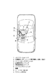
図2は、本発明に係る車両用乗員拘束装置を乗用車に適用した場合の全体構成を示す平面図であり、運転者に対応する拘束装置のみを示している。同図においてコントロールユニット1は、衝突検知及び前後左右の加速度を検出する加速度センサーユニット2(衝突検出手段)からの信号を受けて車両用乗員拘束装置の作動を制御する。加速度センサーユニット2には衝突を検知するとともに、車体前後方向及び車体左右方向のそれぞれの加速度を計測するための加速度センサーが搭載されている。ここで、前面衝突検知用センサをフロントサンドメンバ先端に搭載してもよく、また側面衝突検知用センサをセンターピラー下端に搭載しても良い。
【0032】
シートベルトプリテンショナ3は、衝突初期にシートベルトのたるみを除去するようシートベルトを巻き込み、乗員7を拘束する拘束装置であり、ロードリミッタ機能も併せ持っている。前面衝突用エアバッグ4は、前面衝突時に乗員7とステアリング等車体部品との干渉による衝撃を吸収するための前後方向拘束装置である。
【0033】
側面衝突用エアバッグ5は、側面衝突時に乗員7とピラー等車体部品との干渉による衝撃を吸収するための左右方向拘束装置である。バックルプリテンショナ6は、シートベルトに張力をあたえるべく、シートベルトのバックルを客室後方へ引き込む拘束装置である。
【0034】
上記シートベルトプリテンショナ3,前面衝突用エアバッグ4,側面衝突用エアバッグ5,及びバックルプリテンショナ6は、コントロールユニット1からの信号によりその作動タイミングが制御されるよう構成されている。
【0035】
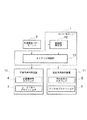
図1は、本発明に係る車両用乗員拘束装置の第1実施形態の構成を示すブロック図である。図1において、車両用乗員拘束装置は、車両の衝突を検出する衝突検出手段である加速度センサーユニット2と、乗員を前後方向に拘束する前後方向拘束手段である前後方向拘束装置10と、乗員を左右方向に拘束する左右方向拘束手段である左右方向拘束装置11と、加速度センサーユニット2からの信号により、前後方向拘束装置10及び左右方向拘束装置11を作動させるタイミングを制御するタイミング制御手段であるタイミング制御部13と、乗員の前後方向移動量と左右方向移動量とをそれぞれ推定する移動量推定手段である移動量推定部12と、を備え、タイミング制御部13は、推定された前後方向移動量及び左右方向移動量に基づいて、前後方向拘束装置10(または左右方向拘束装置11)を作動させてから、左右方向拘束装置11(または前後方向拘束装置10)を作動させるまでの作動遅延時間を演算し、該作動遅延時間は、前後方向移動量(または左右方向移動量)に比例し、かつ左右方向移動量(前後方向移動量)に反比例するように設定される(請求項1、請求項2)。
【0036】
ここで、移動量推定部12とタイミング制御部13とは、コントロールユニット1としてまとめて実装されている。また乗員を前後方向に拘束する前後方向拘束装置10は、前面衝突用エアバッグ4及びシートベルトプリテンショナ3であり、左右方向に拘束する左右方向拘束装置11は、側面衝突用エアバッグ5及びバックルプリテンショナ6である。
【0037】
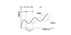
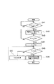
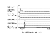
次に、図3のフローチャート及び図4、図5のタイムチャートを参照して、第1実施形態の動作について説明する。図4(a)は、第1実施形態における前面衝突時のタイムチャートであり、図4(b)は、第1実施形態における側面衝突時のタイムチャートである。図6は、斜め前面衝突時における前後方向の加速度(前後G)及び左右方向の加速度(左右G)の時間変化と図3のフローチャートの各ステップS1〜S9の対応を示すタイムチャートである。
【0038】
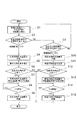
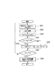
図3において、はじめに、加速度センサーユニット2が検出した車両の前後方向及び左右方向の加速度をコントロールユニット1が読み込む(ステップS1)。次いで、前後方向の加速度が所定値を超えるか否かにより前面衝突したか否かを判定する(ステップS2)。前後方向の加速度が所定値を超えていれば、前面衝突と判定しステップS4へ進む。前後方向の加速度が所定値を超えていなければ、次いで、左右方向の加速度が所定値を超えるか否かにより側面衝突したか否かを判定する(ステップS3)。左右方向の加速度が所定値を超えていれば、側面衝突と判定しステップS10へ進む。左右方向の加速度が所定値を超えていなければ、衝突はないとして、ステップS1へ戻る。
【0039】
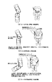
ステップS2で前面衝突と判定したとき、前後方向拘束装置10である前面衝突用エアバッグ4及びシートベルトプリテンショナ3を作動させる(ステップS4)。この間の車両および乗員の挙動は、図15(b)に示すように、車両エンジンコンパートメントが潰れながら、減速する。このとき乗員は、車両に対し相対的に前方移動を開始するが、その移動は前後方向拘束装置の作動により拘束される。
【0040】
次いで、乗員の前後方向及び左右方向移動量を推定し(ステップS5)、これら推定した前後方向移動量及び左右方向移動量に基づいて、乗員の左右方向拘束が必要か否かを判定する(ステップS6)。左右方向拘束が必要でなければ、以上で処理を終了する。左右方向拘束が必要であれば、左右方向拘束装置の作動遅延時間Td1を演算し(ステップS7)、作動遅延時間Td1が経過するまで待つ(ステップS8)。作動遅延時間Td1となると左右方向拘束装置11である側面衝突用エアバッグ5及びバックルプリテンショナ6を作動させる(ステップS9)。
【0041】
ステップS3で側面衝突と判定したとき、左右方向拘束装置11である側面衝突用エアバッグ5、及びシートベルトプリテンショナ3を作動させ(ステップS10)、乗員の前後方向及び左右方向移動量を推定する(ステップS11)。次いで、これら推定した前後方向移動量及び左右方向移動量に基づいて、乗員の前後方向拘束が必要か否かを判定する(ステップS12)。前後方向拘束が必要でなければ、以上で処理を終了する。前後方向拘束が必要であれば、前後方向拘束装置の作動遅延時間Td2を演算し(ステップS13)、作動遅延時間Td2が経過するまで待つ(ステップS14)。作動遅延時間Td2となると前後方向拘束装置10である前面衝突用エアバッグ4、及びバックルプリテンショナ6を作動させる(ステップS15)。
【0042】
次に、前面衝突時の前後方向拘束装置作動後に行うステップS6の左右方向の拘束が必要かどうかの判断から、ステップS9の左右方向拘束装置の作動までの詳細例を図5の詳細フローチャートに示す。尚、以下の説明では、作動遅延時間Td1と作動遅延時間Td2とを特に区別せずに作動遅延時間Tdと表記する。
【0043】
図5において、前後方向拘束装置の作動後のステップS31で、車体前後方向加速度(以下、前後Gと略す)、左右方向加速度(以下、左右Gと略す)、衝突後又は前後方向拘束装置10の作動後の経過時間Ts(t)が計測される。続くステップS32では、前後Gおよび左右Gに基づいて乗員の前後方向移動量と左右方向移動量を推定し、これら推定移動量により左右方向拘束装置11の作動遅延時間Tdが演算される(請求項4)。
【0044】
ここで作動遅延時間Tdは、左右方向移動量の推測から決定されるものであり、前後Gが大きいほど大きく、左右Gが大きいほど小さく定義され、*を乗算記号として、例えば、次に示す式(1)により演算されるものとする。
【0045】
【数1】
Td(t)=f(前後G(t))*前後G(t)/左右G(t) …(1)
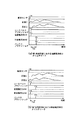
ここで、前後Gの増加に対して単調増加する関数f(前後G(t))は、たとえば、図7(a)に示すような前後Gの線形関係により定義される関数fとしてもよいし(請求項7)、あるいは、図7(b)に示すように、関数fを前後Gの幾何級数で定義し、この関数fを用いて式(1)により作動遅延時間Tdを演算してもよい。
【0046】
また、作動遅延時間Tdは、次に示す式(2)により演算することもできる。
【0047】
【数2】
Td(t)=f(左右G(t))*前後G(t) …(2)
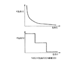
ここで、左右Gの増加に対して単調減少(停留も含む)する関数f(左右G(t))は、図8(a)に示すよう関数fを左右Gの幾何級数に反比例する関数で定義したり(請求項8)、図8(b)に示すよう関数fを左右Gの階段状の関数で定義し(請求項9)、それに前後Gを積算することにより作動遅延時間Tdを求めてもよい。
【0048】
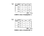
さらに、図16に示すように前後G、左右Gをそれぞれの段階にわけ、その2次元マトリックスの組み合わせで作動遅延時間Tdを定義するようにしてもよい(請求項11)。
【0049】
いずれにせよ、これらの定義により車両左右方向に略平行な単純側面衝突で左右方向拘束装置が作動する場合に発生する左右Gより小さい左右Gでも、前後Gの状態によっては左右方向拘束装置が作動するように定義される。すなわち、従来の左右方向拘束装置が作動しない10G程度の左右Gでも、前面衝突時の前後方向拘束装置作動後に、左右方向拘束装置を作動させることが可能である(請求項3)。
【0050】
このようにして演算された左右方向拘束装置の作動遅延時間Tdと、衝突開始時刻を基準とした現在の時刻、すなわち衝突発生からの経過時間Ts(t)を加算することによりステップS33で左右方向拘束装置が作動すべき時刻T(t)が決定される。続くステップS34〜S36で前回のタイムステップ、すなわちt−△t時に求められたT(t−△t)と比較され小さいほうをT(t)とする。
【0051】
ステップS37では、ステップ36で求められた作動時刻T(t)と現在の時刻Ts(t)の大小が比較され、作動時刻T(t)の方が大きければ、ステップS31からを繰り返し、作動時刻T(t)の方が小さければ、ステップS38で左右方向拘束装置作動トリガを出力する。このトリガをうけた左右方向拘束装置11すなわち側面衝突用エアバッグ5および、バックルプリテンショナ6は、図3のステップS9で左右方向拘束装置を作動させ一連の作動を終了する。
【0052】
一方、図3のステップS3で側面衝突と判断した場合、ステップS10に進み、左右方向拘束装置11すなわち側面衝突用エアバッグ5を作動させ、またシートベルトプリテンショナ3を作動させる。次いで乗員の前後方向及び左右方向移動量を推定し(ステップS11)、これら推定した前後方向移動量及び左右方向移動量に基づいて、乗員の前後方向拘束が必要か否かを判定する(ステップS12)。
【0053】
ステップS12における前後方向拘束が必要か否かの判断のフローは、前面衝突時のステップS6の判断と同様である。ただし、側面衝突時に左右方向拘束装置11を作動させた後の前後方向拘束装置10の作動遅延時間Td2は、前後Gが大きいほど小さく、左右Gが大きいほど大きく定義される。
【0054】
この作動遅延時間Td2の演算に用いられる式は、前後衝突時の式(1)、式(2)に代えて、次に示す式(3)、式(4)を用いる。
【0055】
【数3】
Td2(t)=f(左右G(t))*左右G(t)/前後G(t) …(3)
ここで、左右Gの増加に対して単調増加する関数f(左右G(t))は、たとえば、左右Gの線形関係により定義される関数fとしてもよいし(請求項7)、あるいは、関数fを左右Gの幾何級数で定義し、この関数fを用いて式(3)により作動遅延時間Td2を演算してもよい。
【0056】
また、作動遅延時間Td2は、次に示す式(4)により演算することもできる。
【0057】
【数4】
Td2(t)=f(前後G(t))*左右G(t) …(4)
これらの式(3)、(4)の説明は、図7、図8の「前後」を「左右」と読み替え、「左右」を「前後」と読み替えて、参照することができる。
【0058】
こうして、側面衝突時に、従来の前後方向拘束装置が作動する限界の前後Gより小さい前後Gでも、左右Gの状態によっては前後方向拘束装置が作動するように定義される(請求項3)。
【0059】
すなわち、従来の前後方向拘束装置が作動しない10G程度の前後Gでも、側面衝突時に左右方向拘束装置を作動させた後に前後方向拘束装置を作動させることが可能である。続くステップS15で前後方向拘束装置10すなわち前面衝突用エアバッグ4を作動させ、またバックルプリテンショナ6を作動させて一連の作動を終了する。
【0060】
以上のように前後方向拘束装置の作動後に車体にかかる前後加速度及び左右加速度から乗員の移動量を推定し、左右方向拘束装置の作動の必要性を判断すること、あるいは、左右方向拘束装置の作動後に車体にかかる前後加速度及び左右加速度から乗員の移動量を推定し、前後方向拘束装置の作動の必要性を判断することにより、従来の斜め衝突のような前後方向拘束装置または左右方向拘束装置のいずれか一方しか作動しない、または作動遅れが発生する可能性があるような状況でも乗員の移動を確実に拘束するために十分な拘束装置作動の応答性が得ることが可能となる。
【0061】
〔第2実施形態〕
次に、本発明の第2実施形態を図面を参照して説明する。
第2実施形態は、前面衝突の場合に作用を特化した場合である。第2実施形態の構成は、第1実施形態に対してシートベルトにかかる張力を検出するシートベルト張力計8、図示していないシート座面圧力計10、シート位置検出装置11を付加したものであり、シートベルト張力計8は衝突後のシートベルト張力を計測し、コントロールユニット1にその計測値を送るよう構成されている。
【0062】
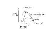
動作フローは第1実施形態と同様である。ただし、図3のステップS6の左右方向拘束の必要性の判定、及びステップS7の左右方向拘束装置の作動遅延時間Tdの演算には、図9,10、11に示すようシートベルト張力が使用される(請求項5)。
【0063】
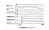
図9は、第2実施形態の動作を説明するタイムチャートであり、図10は第2実施形態の要部の動作を説明するフローチャートである。また図11は、シートベルト張力F(t)と、所定のシートベルト張力閾値Cf(t)とを示すタイムチャートである。
【0064】
図10において、まず、ステップS41でシートベルトプリテンショナ3の作動が確認された後、ステップS42で、シートベルト張力F(t)、前後方向拘束装置の作動後の経過時間Ts(t)が計測される。続くステップS43では、あらかじめ設定されているシートベルト張力閾値Cf(t)とシートベルト張力F(t)が比較される。
【0065】
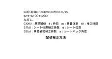
シートベルト張力閾値Cf(t)は、図17に示すよう前後G、乗員の体格、シート位置、乗車姿勢により補正される(請求項12)。ただし、シート位置補正係数S1(d)はシート位置が可動範囲の中央の場合を0とし、それより前方の場合、シート位置補正係数S1(d)は−の値で前方ほど小さい値をとるよう、後方の場合+の値で後方ほど大きい値となるよう定義される。また乗車姿勢補正係数S2(a)は、乗車姿勢として、シートバック角度を計測使用しており、シートバック角度20°の場合を0とし、それより角度が小さい場合、乗車姿勢補正係数S2(a)は−の値で前方ほど小さい値をとるよう、角度が20°より大きい場合は乗車姿勢補正係数S2(a)は+の値で角度が大きいほど大きい値となるよう定義される。
【0066】
シートベルト張力計8が検出するシートベルト張力F(t)は、そのピーク値が大きいほど、また張力持続時間が長いほど、乗員の左右方向移動量が小さい。従って、シートベルト張力と張力持続時間により乗員の左右方向移動量を演算することができる(請求項5)。
【0067】
これにより、図11に示す単純側面衝突時に発生するシートベルト張力よりも大きく、持続時間も大きい範囲、すなわち、単純側面衝突で発生する乗員左右方向移動量より小さい場合でも、左右方向拘束装置作動の必要性の判定されることになる。ステップS42〜S43は、シートベルト張力F(t)がシートベルト張力閾値Cf(t)より小さくなるまで繰り返される。F(t)の方がCf(t)より小さい場合は、続くステップS44で左右方向拘束装置の作動遅延時間Tdと、現在の時刻、すなわち衝突発生からの経過時間Ts(t)を加算することにより、左右方向拘束装置の作動時刻Tが決定される。ここで左右方向拘束装置の作動遅延時間Tdは一定値とする。
【0068】
ステップS45では、ステップS44で求められた作動時刻Tと現在の時刻Ts(t)の大小が比較され、作動時刻Tの方が大きければ、引き続きステップS46で現在の時刻Ts(t)を計測、ステップS45を繰り返し、作動時刻Tの方が現在の時刻Ts(t)より小さい場合、ステップS46で左右方向拘束装置作動トリガを出力する。このトリガをうけた左右方向拘束装置11すなわち側面衝突用エアバッグ5及びバックルプリテンショナ6は、図3ステップS9で左右方向拘束装置を作動させ一連の作動を終了する。
【0069】
以上のように第2実施形態では、第1実施形態と同様の効果が得られるのに加え、シートベルト張力から前面衝突後の乗員の左右方向移動量および移動開始をより正確に推定することが可能となる。
【0070】
〔第3実施形態〕
次に、本発明の第3実施形態を図面を参照して説明する。
第3実施形態は、前面衝突の場合に作用を特化した場合である。第3実施形態の構成は、第1実施形態に前面衝突用エアバッグ内圧計9、図示していないシート座面圧力計10、シート位置検出装置11を付加したものであり、前面衝突用エアバッグ内圧計9は衝突後の前面衝突用エアバッグ4の内圧を計測し、コントロールユニット1にその計測値を送るよう構成されている。
【0071】
動作フローは第1実施形態と同様である。ただし、図3のステップS6の左右方向拘束の必要性の判定、ないしステップS7の左右方向拘束装置の作動遅延時間Tdの演算には、図12,13、14に示すように前面衝突用エアバッグ内圧が使用される(請求項6)。
【0072】
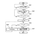
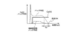
図12は、第3実施形態の動作を説明するタイムチャートである。図13は、第3実施形態の要部の動作を説明するフローチャートである。図14は、前面衝突用エアバッグ内圧P(t)と、所定の前面衝突用エアバッグ内圧閾値Cp(t)とを説明するタイムチャートである。
【0073】
図13において、ステップS51で前面衝突用エアバッグ4の作動が確認された後、ステップS52で、前面衝突用エアバッグ内圧P(t)、前後方向拘束装置の作動後の経過時間Ts(t)が計測される。続くステップS53では、あらかじめ設定されている前面衝突用エアバッグ内圧閾値Cp(t)と前面衝突用エアバッグ内圧P(t)が比較される。
【0074】
前面衝突用エアバッグ内圧閾値Cp(t)は、図17に示すよう前後G、乗員の体格、乗車位置、乗車姿勢により補正される(請求項12)。ここで、エアバッグ内圧はそのピーク値が大きいほど、また内圧持続時間が長いほど、乗員の左右方向移動量が小さい。したがって、図14に示す単純側面衝突時に発生するエアバッグ内圧よりも大きく、持続時間も大きい範囲、すなわち、単純側面衝突で発生する乗員左右方向移動量より小さい場合でも、左右方向拘束の必要性が判定されることになる。ステップS52〜S53は、P(t)がCp(t)より小さくなるまで繰り返される。
【0075】
P(t)の方がCp(t)より小さい場合は、続くステップS54でTdと現在の時刻、すなわち衝突発生からの経過時間Ts(t)を加算することにより左右方向拘束装置の作動時刻Tが決定される。ここで左右方向拘束装置の作動遅延時間Tdは一定値とする。ステップS55では、ステップS54で求められた作動時刻Tと現在の時刻Ts(t)の大小が比較され、作動時刻Tの方が大きければ、引き続きステップS56で現在の時刻Ts(t)を計測、ステップS55を繰り返し、作動時刻Tの方が現在の時刻Ts(t)より小さい場合、ステップS56で左右方向拘束装置の作動トリガを出力する。このトリガをうけた左右方向拘束装置11すなわち側面衝突用エアバッグ5及びバックルプリテンショナ6は、図3のステップS9で左右方向拘束装置を作動させ一連の作動を終了する。
【0076】
以上のように第3実施形態では、第1実施形態と同様の効果が得られるのに加え、前面衝突用エアバッグ内圧から前面衝突後の乗員の左右方向移動量および移動開始をより正確に推定することが可能となる。
【図面の簡単な説明】
【図1】本発明に係る車両用乗員拘束装置の第1実施形態の構成を示すブロック図である。
【図2】本発明に係る車両用乗員拘束装置の全体構成を示す平面図である。
【図3】第1実施形態の動作を説明するフローチャートである。
【図4】(a)第1実施形態における前面衝突時のタイムチャート、(b)第1実施形態における側面衝突時のタイムチャートである。
【図5】第1実施形態の前後方向(左右方向)拘束装置作動後の左右方向(前後方向)拘束装置の作動遅延時間を決定するフローチャートである。
【図6】斜め前面衝突時の車体加速度発生例を示すタイムチャートである。
【図7】第1実施形態における作動遅延時間の定義説明図である。
【図8】第1実施形態における作動遅延時間の定義説明図である。
【図9】第2実施形態の動作を説明するタイムチャートである。
【図10】第2実施形態における前後方向拘束装置作動後の左右方向拘束装置の作動遅延時間を決定するフローチャートである。
【図11】第2実施形態におけるシートベルト張力閾値の説明図である。
【図12】第3実施形態の動作を説明するタイムチャートである。
【図13】第3実施形態における前後方向拘束装置作動後の左右方向拘束装置の作動遅延時間を決定するフローチャートである。
【図14】第3実施形態における前面衝突用エアバッグ内圧閾値の説明図である。
【図15】実施形態作動時の車両および乗員の挙動を説明する図である。
【図16】第1実施形態における作動遅延時間の定義説明図である。
【図17】第2,3実施形態における閾値補正方法の説明図である。
【符号の説明】
1 コントロールユニット
2 加速度センサユニット
3 シートベルトプリテンショナ
4 前面衝突用エアバッグ
5 側面衝突用エアバッグ
6 バックルプリテンショナ
10 前後方向拘束装置
11 左右方向拘束装置
12 移動量推定部
13 タイミング制御部[0001]
BACKGROUND OF THE INVENTION
The present invention relates to a vehicle occupant restraint device, and more particularly to a vehicle occupant restraint device that restrains an occupant in the front-rear direction and the left-right direction according to the estimated behavior of the occupant.
[0002]
[Prior art]
Conventionally, an occupant restraint device such as a seat belt, an airbag, or a knee pad has been used to protect the occupant in the event of a vehicle collision. In general, a seat belt for a passenger car is mounted asymmetrically with respect to the center line of the occupant body, so that the occupant body is twisted at the time of collision. A technique described in Japanese Patent Application Laid-Open No. 5-39000 is known as a technique for suppressing the twist of the passenger body and maximizing the impact absorption performance. In this conventional technique, the occupant measurement sensor is used to grasp the physique and behavior of the occupant, and the air bag, seat belt, knee pad, and the like are adjusted and controlled to enhance the impact absorption effect at the time of collision.
[0003]
[Problems to be solved by the invention]
However, according to the conventional example, each restraint device is operated according to the displacement of the occupant detected by the occupant measurement sensor. Therefore, in order to restrain the occupant movement reliably, the restraint device operation is not necessarily sufficient for the occupant movement. There is a possibility that a case where the responsiveness cannot be obtained may occur.
[0004]
For example, in the case of an oblique frontal collision as shown in FIG. 15, while the engine compartment absorbs impact energy and is crushed after the collision, the lateral movement amount is small and the lateral acceleration generated in the vehicle body is also small. . However, when the engine compartment is completely crushed, the lateral acceleration is increased by the rotation of the vehicle and the impact force in the lateral direction of the vehicle, and the lateral force acts on the occupant. At this point, the seat belt functions as a load limiter, so the restraining force in the left-right direction is small, and it is not as large as the left-right acceleration of the vehicle body as in a normal side collision. May not work. Even if it operates according to the behavior of the occupant, the airbag or the like takes time to deploy, so that the effect may not be sufficiently exhibited.
[0005]
The present invention has been made in view of the above-described problems of the prior art, and the purpose of the conventional vehicle occupant restraint device is at the time of a collision in which only one restraint device of the front-rear direction restraint device or the left-right direction restraint device operates. In addition, the amount of movement of the occupant in the front-rear direction and the amount of movement in the left-right direction is estimated. It is an object of the present invention to provide a vehicle occupant restraint device capable of maximizing the shock absorbing ability even when there is interference.
[0006]
[Means for Solving the Problems]
In order to achieve the above object, the invention described in
[0007]
In order to achieve the above object, the invention described in
[0008]
According to a third aspect of the present invention, in order to achieve the above object, in the vehicle occupant restraint device according to the first or second aspect, the estimated front-rear direction movement amount and left-right direction movement amount are at least two. The gist is to have a setting area, and the small setting area is set to a value equal to or less than an estimated movement amount generated by a frontal collision substantially parallel to the vehicle longitudinal direction or a side collision substantially parallel to the vehicle lateral direction.
[0009]
According to a fourth aspect of the present invention, in order to achieve the above object, in the vehicle occupant restraint apparatus according to any one of the first to third aspects, the movement amount estimating means is a vehicle longitudinal acceleration applied to a vehicle body. And the lateral movement amount and the lateral movement amount of the occupant are estimated based on the vehicle lateral acceleration applied to the vehicle body.
[0010]
According to a fifth aspect of the present invention, in order to achieve the above object, in the vehicle occupant restraint apparatus according to any one of the first to third aspects, the movement amount estimating means is based on a tension applied to a seat belt. The gist is to estimate the amount of movement of the occupant in the front-rear direction and the amount of movement in the left-right direction.
[0011]
According to a sixth aspect of the present invention, in order to achieve the above object, in the vehicle occupant restraint device according to any one of the first to third aspects, the movement amount estimating means is based on an internal pressure of the airbag. The gist is to estimate the amount of movement of the occupant in the front-rear direction and the amount of movement in the left-right direction.
[0012]
In order to achieve the above object, according to a seventh aspect of the present invention, in the vehicle occupant restraint device according to any one of the first to sixth aspects, the timing control means is an operation delay of the left-right direction restraint means. The gist is to set the time so that the time is linearly inversely proportional to the amount of movement of the occupant and the operation delay time of the front-rear direction restraining means is linearly inversely proportional to the amount of movement of the occupant.
[0013]
In order to achieve the above object, according to an eighth aspect of the present invention, in the vehicle occupant restraint device according to any one of the first to sixth aspects, the timing control means is an operation delay of the left-right direction restraint means. The gist is to set the time inversely proportional to the estimated back-and-forth movement amount by a geometric series, and to set the operation delay time of the front-and-rear direction restraining means to be inversely proportional to the estimated left-and-right direction movement amount by a geometric series. .
[0014]
According to a ninth aspect of the invention, in order to achieve the above object, in the vehicle occupant restraint device according to any one of the first to sixth aspects, the timing control means is an operation delay of the left-right direction restraint means. The gist is to set the time stepwise with respect to the estimated amount of forward and backward movement.
[0015]
According to a tenth aspect of the present invention, in order to achieve the above object, in the vehicle occupant restraint device according to any one of the first to sixth aspects, the timing control means is an operation delay of the front-rear direction restraint means. The gist is to set the time stepwise with respect to the estimated amount of lateral movement.
[0016]
In order to achieve the above object, according to an eleventh aspect of the present invention, in the vehicle occupant restraint device according to the ninth or tenth aspect, the timing control means is an operation delay of the front-rear direction restraint means or the left-right direction restraint means. The gist is that the time is set by a matrix of the estimated front-rear direction movement amount and left-right direction movement amount.
[0017]
According to a twelfth aspect of the present invention, in order to achieve the above object, in the vehicle occupant restraint apparatus according to any one of the first to eleventh aspects, the movement amount estimation means is configured to perform the estimated longitudinal movement. The gist is to correct the amount or the lateral movement amount by at least one of the physique, position, or posture of the occupant.
[0018]
【The invention's effect】
According to the first aspect of the present invention, the collision detection means for detecting the collision of the vehicle, the front-rear direction restraining means for restraining the occupant in the front-rear direction, the left-right direction restraining means for restraining the occupant in the left-right direction, and the collision detection Timing control means for controlling the timing for operating the front-rear direction restraining means and the left-right direction restraining means, and movement amount estimation means for estimating the front-rear direction movement amount and the left-right direction movement amount, respectively, according to signals from the means; The timing control means operates the front-rear direction restraining means based on the estimated front-rear direction movement amount and left-right direction movement amount, and then performs the left-right direction restraint device. An operation delay time until the device is operated is set, and the operation delay time is set to be proportional to the front-rear direction movement amount and inversely proportional to the left-right direction movement amount. did Therefore, the collision direction of the vehicle is detected and the amount of movement of the occupant in the front-rear and left-right directions is estimated. Traditional A simple frontal collision or Simple In a side collision One restraining means is activated and the other Restraint means Even if the occupant movement amount is such that the occupant movement is not activated, the front and rear direction restraining means and the left and right direction restraining means are actuated at appropriate timing with respect to the estimated movement amount, thereby There is an effect that the interference can be minimized and the shock absorption can be maximized when the interference occurs.
[0019]
According to a second aspect of the present invention, a collision detection means for detecting a vehicle collision, a front-rear direction restraining means for restraining the occupant in the front-rear direction, a left-right direction restraining means for restraining the occupant in the left-right direction, and the collision detection Timing control means for controlling the timing for operating the front-rear direction restraining means and the left-right direction restraining means, and movement amount estimation means for estimating the front-rear direction movement amount and the left-right direction movement amount, respectively, according to signals from the means; The timing control means operates the left-right direction restraining means on the basis of the estimated front-rear direction movement amount and left-right direction movement amount, and then performs the front-rear direction restraint device. Set the operation delay time until the device is activated did Therefore, the collision direction of the vehicle is detected and the amount of movement of the occupant in the front-rear and left-right directions is estimated. Traditional A simple frontal collision or Simple In a side collision One restraining means is activated and the other Restraint means Even if the occupant movement amount is such that the occupant movement is not activated, the front and rear direction restraining means and the left and right direction restraining means are actuated at appropriate timing with respect to the estimated movement amount, thereby There is an effect that the interference can be minimized and the shock absorption can be maximized when the interference occurs.
[0020]
According to the invention described in
[0021]
According to the fourth aspect of the present invention, in addition to the effects of the first to third aspects of the invention, the movement amount estimating means includes a vehicle longitudinal acceleration applied to the vehicle body and a vehicle lateral acceleration applied to the vehicle body. Based on this, the occupant's longitudinal and lateral movements are estimated, so the occupant's longitudinal and lateral movements are estimated for both front and side collisions. There is an effect that can be done.
[0022]
According to a fifth aspect of the present invention, in addition to the effects of the first to third aspects of the invention, the movement amount estimation means is configured to determine the amount of movement of the occupant in the front-rear direction and the left-right direction based on the tension applied to the seat belt. Since the amount of movement is estimated, it is possible to grasp the operating state of the restraining means, and it is possible to more directly estimate the temporal change in the amount of movement of the occupant in the front-rear direction and the left-right direction.
[0023]
According to the sixth aspect of the present invention, in addition to the effects of the first to third aspects of the invention, the movement amount estimation means is configured such that the occupant's front-rear direction movement amount and left-right direction movement are based on the internal pressure of the airbag. Therefore, there is an effect that it is possible to grasp the operating state of the restraint means and more directly estimate the temporal change of the movement amount of the occupant in the front-rear direction and the left-right direction.
[0024]
According to a seventh aspect of the invention, in addition to the effects of the first to sixth aspects of the invention, the timing control means linearly sets the operation delay time of the left-right direction restraining means to the occupant's back-and-forth movement amount. Since the operation delay time of the front / rear direction restraining means is set to be inversely proportional to the amount of lateral movement of the occupant, the operation delay time of the restraint device can be set in more detail.
[0025]
According to an eighth aspect of the invention, in addition to the effects of the first to sixth aspects of the invention, the timing control means determines the operation delay time of the left-right direction restraining means as the estimated front-rear direction movement amount. The operation delay time of the front-rear direction restraining means is set to be inversely proportional to the estimated lateral movement amount by the geometric series, so that the operation delay time of the restraint device can be set in more detail. effective.
[0026]
According to the ninth aspect of the present invention, in addition to the effects of the first to sixth aspects of the invention, the timing control means determines the operation delay time of the left-right direction restraining means as the estimated back-and-forth movement amount. In contrast, since the delay time is set stepwise, it is possible to easily set the operation delay time of the restraint device.
[0027]
According to a tenth aspect of the present invention, in addition to the effects of the first to sixth aspects of the invention, the timing control means sets the operation delay time of the front-rear direction restraining means to the estimated left-right movement amount. In contrast, since the delay time is set stepwise, it is possible to easily set the operation delay time of the restraint device.
[0028]
According to the eleventh aspect of the invention, in addition to the effect of the ninth or tenth aspect of the invention, the timing control means is configured to estimate the operation delay time of the front-rear direction restraining means or the left-right direction restraining means. Further, since the setting is made by the matrix of the amount of movement in the front-rear direction and the amount of movement in the left-right direction, there is an effect that the operation delay time setting of the restraint device can be facilitated.
[0029]
According to a twelfth aspect of the present invention, in addition to the effects of the first to eleventh aspects of the invention, the movement amount estimating means at least determines the estimated front-rear direction movement amount or left-right direction movement amount of the occupant. Since the correction was made based on either the physique or the position or posture, it is possible to estimate a more accurate movement amount of the occupant, and to set a more appropriate operation delay time of the restraint device based on this. effective.
[0030]
DETAILED DESCRIPTION OF THE INVENTION
DESCRIPTION OF EMBODIMENTS Hereinafter, embodiments of a vehicle occupant restraint device according to the present invention will be described in detail with reference to the drawings.
[0031]
[First Embodiment]
FIG. 2 is a plan view showing the overall configuration when the vehicle occupant restraint device according to the present invention is applied to a passenger car, and shows only the restraint device corresponding to the driver. In the figure, a
[0032]
The
[0033]
The
[0034]
The
[0035]
FIG. 1 is a block diagram showing a configuration of a first embodiment of a vehicle occupant restraint device according to the present invention. In FIG. 1, the vehicle occupant restraint device includes an
[0036]
Here, the movement amount estimation unit 12 and the
[0037]
Next, the operation of the first embodiment will be described with reference to the flowchart of FIG. 3 and the time charts of FIGS. FIG. 4A is a time chart at the time of a frontal collision in the first embodiment, and FIG. 4B is a time chart at the time of a side collision in the first embodiment. FIG. 6 is a time chart showing the correspondence between the temporal change in the longitudinal acceleration (front-rear G) and the lateral acceleration (left-right G) in a diagonal frontal collision and the steps S1 to S9 in the flowchart of FIG.
[0038]
In FIG. 3, first, the
[0039]
When it is determined in step S2 that a frontal collision has occurred, the
[0040]
Next, the occupant's longitudinal and lateral movement amounts are estimated (step S5), and it is determined whether the occupant's lateral restraint is necessary based on the estimated longitudinal and lateral movement amounts (step S5). S6). If the left-right direction constraint is not necessary, the process ends. If the left and right direction restraint is necessary, the operation delay time Td1 of the left and right direction restraint device is calculated (step S7), and the process waits until the operation delay time Td1 elapses (step S8). When the operation delay time Td1 is reached, the
[0041]
When it is determined in step S3 that a side collision has occurred, the
[0042]
Next, the detailed flowchart of FIG. 5 shows a detailed example from the determination of whether the restraint in the left-right direction in step S6 required after the operation of the front-rear direction restraint device at the time of the frontal collision to the operation of the left-right restraint device in step S9. . In the following description, the operation delay time Td1 and the operation delay time Td2 are expressed as the operation delay time Td without any particular distinction.
[0043]
5, in step S31 after the operation of the front-rear direction restraint device, the vehicle body front-rear direction acceleration (hereinafter abbreviated as “front-rear G”), left-right direction acceleration (hereinafter referred to as “right-left G”), The elapsed time Ts (t) after the operation is measured. In the subsequent step S32, the amount of movement of the occupant in the front-rear direction and the amount of left-right movement is estimated based on the front-rear G and the left-right G, and the operation delay time Td of the left-right
[0044]
Here, the operation delay time Td is determined based on the estimation of the lateral movement amount, and is defined to be larger as the front and rear G is larger and smaller as the left and right G is larger. It shall be calculated by (1).
[0045]
[Expression 1]
Td (t) = f (front and rear G (t)) * front and rear G (t) / left and right G (t) (1)
Here, the function f (front and rear G (t)) monotonously increasing with respect to the increase and decrease of front and rear G may be a function f defined by the linear relationship of front and rear G as shown in FIG. (Claim 7) Or, as shown in FIG. 7 (b), the function f is defined by a geometric series of front and rear G, and the operation delay time Td is calculated by the equation (1) using this function f. Good.
[0046]
Further, the operation delay time Td can be calculated by the following equation (2).
[0047]
[Expression 2]
Td (t) = f (left and right G (t)) * front and rear G (t) (2)
Here, the function f (right and left G (t)) that monotonously decreases (including stationary) with respect to the increase in the left and right G is a function that is inversely proportional to the geometric series of the left and right G as shown in FIG. The function f is defined by a stepwise function of right and left G as shown in FIG. 8B (claim 9), and the operation delay time Td is obtained by adding the front and rear G to it. May be.
[0048]
Further, as shown in FIG. 16, the front and rear G and the left and right G may be divided into respective stages, and the operation delay time Td may be defined by a combination of the two-dimensional matrix.
[0049]
In any case, the left and right direction restraint device is activated depending on the state of the front and rear G even when the left and right direction G is smaller than the left and right G generated when the left and right direction restraint device is activated by a simple side collision substantially parallel to the left and right direction of the vehicle. To be defined. That is, even in the left and right G of about 10G where the conventional left and right direction restraint device does not work, the left and right direction restraint device can be actuated after the front and rear direction restraint device is actuated at the time of a frontal collision.
[0050]
In step S33, the operation delay time Td of the left-right direction restraint device calculated in this way and the current time based on the collision start time, that is, the elapsed time Ts (t) from the occurrence of the collision, are added in the left-right direction in step S33. A time T (t) at which the restraint device is to be activated is determined. In subsequent steps S34 to S36, the smaller time is compared with T (t-Δt) obtained at the previous time step, that is, t-Δt, and T (t) is set as the smaller one.
[0051]
In step S37, the operation time T (t) obtained in step 36 is compared with the current time Ts (t). If the operation time T (t) is greater, step S31 is repeated, and the operation time If T (t) is smaller, a left / right direction restraint device operation trigger is output in step S38. The left-right
[0052]
On the other hand, if it is determined in step S3 of FIG. 3 that a side collision has occurred, the process proceeds to step S10, where the
[0053]
The flow for determining whether or not front-rear direction restraint is necessary in step S12 is the same as the determination in step S6 at the time of frontal collision. However, the operation delay time Td2 of the front-rear
[0054]
The following formulas (3) and (4) are used in place of the formulas (1) and (2) at the time of the front-rear collision, as formulas used for calculating the operation delay time Td2.
[0055]
[Equation 3]
Td2 (t) = f (left and right G (t)) * left and right G (t) / front and back G (t) (3)
Here, the function f (right and left G (t)) monotonously increasing with respect to the increase in left and right G may be, for example, a function f defined by a linear relationship between left and right G (Claim 7), or It is also possible to define f as a geometric series of left and right G, and to calculate the operation delay time Td2 by the expression (3) using this function f.
[0056]
Further, the operation delay time Td2 can be calculated by the following equation (4).
[0057]
[Expression 4]
Td2 (t) = f (front and rear G (t)) * left and right G (t) (4)
The expressions (3) and (4) can be referred to by replacing “front and rear” in FIGS. 7 and 8 with “left and right” and “left and right” with “front and back”.
[0058]
Thus, it is defined that the front-rear direction restraint device is activated depending on the state of the left-right G even when the front-rear G is smaller than the front-rear direction G where the conventional front-rear direction restraint device operates at the time of a side collision.
[0059]
That is, it is possible to operate the front-rear direction restraint device after operating the left-right direction restraint device even in the front-rear direction G of about 10 G where the conventional front-rear direction restraint device does not operate. In the following step S15, the front-rear
[0060]
As described above, the movement amount of the occupant is estimated from the longitudinal acceleration and the lateral acceleration applied to the vehicle body after the actuation of the longitudinal restraint device, and the necessity of the actuation of the lateral restraint device is judged, or the actuation of the lateral restraint device is activated. The amount of movement of the occupant is estimated from the longitudinal acceleration and the lateral acceleration applied to the vehicle body later, and the necessity of the operation of the longitudinal restraint device is judged. Even in a situation in which only one of them operates or there is a possibility that an operation delay may occur, it is possible to obtain sufficient restraint device responsiveness to reliably restrain the movement of the occupant.
[0061]
[Second Embodiment]
Next, a second embodiment of the present invention will be described with reference to the drawings.
2nd Embodiment is a case where an effect | action is specialized in the case of frontal collision. The configuration of the second embodiment is obtained by adding a seat
[0062]
The operation flow is the same as in the first embodiment. However, the seat belt tension is used as shown in FIGS. 9, 10 and 11 for the determination of the necessity of the right / left restraint in step S6 in FIG. 3 and the calculation of the operation delay time Td of the left / right restraint device in step S7. (Claim 5).
[0063]
FIG. 9 is a time chart for explaining the operation of the second embodiment, and FIG. 10 is a flowchart for explaining the operation of the main part of the second embodiment. FIG. 11 is a time chart showing the seat belt tension F (t) and a predetermined seat belt tension threshold Cf (t).
[0064]
In FIG. 10, first, after the operation of the
[0065]
The seat belt tension threshold Cf (t) is corrected by the front and rear G, the occupant's physique, the seat position, and the riding posture as shown in FIG. However, the sheet position correction coefficient S1 (d) is set to 0 when the sheet position is in the center of the movable range, and the sheet position correction coefficient S1 (d) is a negative value and becomes smaller toward the front when the sheet position is ahead. In the case of the rear, it is defined to be a positive value with a larger value toward the rear. The riding posture correction coefficient S2 (a) measures and uses the seat back angle as the riding posture. When the seat back angle is 20 °, the riding posture correction coefficient S2 (a) is 0. ) Is defined as a negative value that is smaller toward the front, and when the angle is greater than 20 °, the riding posture correction coefficient S2 (a) is a positive value that increases as the angle increases.
[0066]
The seat belt tension F (t) detected by the seat
[0067]
As a result, even if the seat belt tension is greater than the seat belt tension generated during a simple side collision shown in FIG. The necessity will be determined. Steps S42 to S43 are repeated until the seat belt tension F (t) becomes smaller than the seat belt tension threshold Cf (t). If F (t) is smaller than Cf (t), the operation delay time Td of the left / right direction restraint device and the current time, that is, the elapsed time Ts (t) from the occurrence of the collision are added in the subsequent step S44. Thus, the operation time T of the left-right direction restraining device is determined. Here, the operation delay time Td of the right-and-left restraining device is a constant value.
[0068]
In step S45, the operating time T obtained in step S44 is compared with the current time Ts (t). If the operating time T is greater, the current time Ts (t) is continuously measured in step S46. Step S45 is repeated, and if the operation time T is smaller than the current time Ts (t), a left-right direction restraint device operation trigger is output in step S46. The left-right
[0069]
As described above, in the second embodiment, in addition to obtaining the same effect as in the first embodiment, it is possible to more accurately estimate the lateral movement amount and the movement start of the occupant after the frontal collision from the seat belt tension. It becomes possible.
[0070]
[Third Embodiment]
Next, a third embodiment of the present invention will be described with reference to the drawings.
3rd Embodiment is a case where an effect | action is specialized in the case of frontal collision. The configuration of the third embodiment is obtained by adding a front collision airbag
[0071]
The operation flow is the same as in the first embodiment. However, as shown in FIGS. 12, 13, and 14, the front collision airbag is used for determining the necessity of right / left restraint in step S6 in FIG. 3 or for calculating the operation delay time Td of the left / right restraint device in step S7. Internal pressure is used (Claim 6).
[0072]
FIG. 12 is a time chart for explaining the operation of the third embodiment. FIG. 13 is a flowchart for explaining the operation of the main part of the third embodiment. FIG. 14 is a time chart for explaining the front collision airbag internal pressure P (t) and a predetermined front collision airbag internal pressure threshold Cp (t).
[0073]
In FIG. 13, after the operation of the
[0074]
The front collision airbag internal pressure threshold Cp (t) is corrected by the front and rear G, the occupant's physique, the boarding position, and the boarding posture as shown in FIG. Here, the greater the peak value of the airbag internal pressure and the longer the internal pressure duration, the smaller the amount of movement of the occupant in the left-right direction. Therefore, even in the case where the air bag internal pressure generated during a simple side collision shown in FIG. 14 is larger and the duration is longer, that is, smaller than the lateral movement amount of the occupant generated during the simple side collision, there is a need for left-right restraint. Will be judged. Steps S52 to S53 are repeated until P (t) becomes smaller than Cp (t).
[0075]
If P (t) is smaller than Cp (t), in the following step S54, Td and the current time, that is, the elapsed time Ts (t) from the occurrence of the collision, are added, so that the operation time T of the left / right direction restraint device is reached. Is determined. Here, the operation delay time Td of the right-and-left restraining device is a constant value. In step S55, the operating time T obtained in step S54 is compared with the current time Ts (t). If the operating time T is larger, the current time Ts (t) is continuously measured in step S56. Step S55 is repeated, and if the operation time T is smaller than the current time Ts (t), an operation trigger for the left / right direction restraint device is output in step S56. The left-right
[0076]
As described above, in the third embodiment, in addition to obtaining the same effects as those in the first embodiment, the lateral movement amount and the start of movement of the occupant after the frontal collision are more accurately estimated from the frontal collision airbag internal pressure. It becomes possible to do.
[Brief description of the drawings]
FIG. 1 is a block diagram showing a configuration of a first embodiment of a vehicle occupant restraint device according to the present invention.
FIG. 2 is a plan view showing the overall configuration of the vehicle occupant restraint device according to the present invention.
FIG. 3 is a flowchart for explaining the operation of the first embodiment;
4A is a time chart at the time of a frontal collision in the first embodiment, and FIG. 4B is a time chart at the time of a side collision in the first embodiment.
FIG. 5 is a flowchart for determining the operation delay time of the left-right direction (front-rear direction) restraint device after the front-rear direction (left-right direction) restraint device is actuated according to the first embodiment;
FIG. 6 is a time chart showing an example of vehicle body acceleration occurring at a diagonal frontal collision.
FIG. 7 is an explanatory diagram for defining an operation delay time in the first embodiment.
FIG. 8 is an explanatory diagram for defining an operation delay time in the first embodiment.
FIG. 9 is a time chart for explaining the operation of the second embodiment.
FIG. 10 is a flowchart for determining an operation delay time of the left-right direction restraint device after the operation of the front-rear direction restraint device in the second embodiment.
FIG. 11 is an explanatory diagram of a seat belt tension threshold value according to the second embodiment.
FIG. 12 is a time chart for explaining the operation of the third embodiment.
FIG. 13 is a flowchart for determining an operation delay time of the left-right direction restraint device after the operation of the front-rear direction restraint device in the third embodiment.
FIG. 14 is an explanatory diagram of a frontal collision airbag internal pressure threshold in the third embodiment.
FIG. 15 is a diagram for explaining the behavior of a vehicle and an occupant during operation of the embodiment.
FIG. 16 is a diagram illustrating the definition of an operation delay time in the first embodiment.
FIG. 17 is an explanatory diagram of a threshold correction method in the second and third embodiments.
[Explanation of symbols]
1 Control unit
2 Acceleration sensor unit
3 Seat belt pretensioner
4 Front collision airbag
5 Side impact airbag
6 Buckle pretensioner
10 Longitudinal restraint device
11 Left and right direction restraint device
12 Movement amount estimation part
13 Timing controller
Claims (12)
乗員を前後方向に拘束する前後方向拘束手段と、
乗員を左右方向に拘束する左右方向拘束手段と、
前記衝突検出手段からの信号により、前記前後方向拘束手段及び前記左右方向拘束手段を作動させるタイミングを制御するタイミング制御手段と、
乗員の前後方向移動量と左右方向移動量とをそれぞれ推定する移動量推定手段と、
を備えた車両用乗員拘束装置であって、
前記タイミング制御手段は、
前記推定された前後方向移動量及び左右方向移動量に基づいて、
前記前後方向拘束手段を作動させてから前記左右方向拘束手段を作動させるまでの作動遅延時間を設定し、
該作動遅延時間は、
前記前後方向移動量に比例し、かつ前記左右方向移動量に反比例するように設定されることを特徴とする車両用乗員拘束装置。Collision detection means for detecting a vehicle collision;
A front-rear direction restraining means for restraining an occupant in the front-rear direction;
A left-right direction restraining means for restraining an occupant in the left-right direction;
A timing control means for controlling the timing for operating the front-rear direction restraining means and the left-right direction restraining means according to a signal from the collision detection means;
A movement amount estimating means for estimating the movement amount of the occupant in the front-rear direction and the movement amount in the left-right direction,
A vehicle occupant restraint device comprising:
The timing control means includes
Based on the estimated front-rear direction movement amount and left-right direction movement amount,
Set an operation delay time from operating the front-rear direction restraining means to activating the left-right direction restraining means,
The operation delay time is
The vehicle occupant restraint apparatus is set to be proportional to the amount of movement in the front-rear direction and inversely proportional to the amount of movement in the left-right direction.
乗員を前後方向に拘束する前後方向拘束手段と、
乗員を左右方向に拘束する左右方向拘束手段と、
前記衝突検出手段からの信号により、前記前後方向拘束手段及び前記左右方向拘束手段を作動させるタイミングを制御するタイミング制御手段と、
乗員の前後方向移動量と左右方向移動量とをそれぞれ推定する移動量推定手段と、
を備えた車両用乗員拘束装置であって、
前記タイミング制御手段は、
前記推定された前後方向移動量及び左右方向移動量に基づいて、
前記左右方向拘束手段を作動させてから前記前後方向拘束手段を作動させるまでの作動遅延時間を設定し、
該作動遅延時間は、
前記左右方向移動量に比例し、かつ前記前後方向移動量に反比例するように設定されることを特徴とする車両用乗員拘束装置。Collision detection means for detecting a vehicle collision;
A front-rear direction restraining means for restraining an occupant in the front-rear direction;
A left-right direction restraining means for restraining an occupant in the left-right direction;
A timing control means for controlling the timing for operating the front-rear direction restraining means and the left-right direction restraining means according to a signal from the collision detection means;
A movement amount estimating means for estimating the movement amount of the occupant in the front-rear direction and the movement amount in the left-right direction,
A vehicle occupant restraint device comprising:
The timing control means includes
Based on the estimated front-rear direction movement amount and left-right direction movement amount,
Set an operation delay time from operating the left-right direction restraining means to operating the front-rear direction restraining means,
The operation delay time is
The vehicle occupant restraint device is set so as to be proportional to the lateral movement amount and inversely proportional to the longitudinal movement amount.
小さい設定域は、
車両前後方向に略平行な前面衝突または
車両左右方向に略平行な側面衝突で発生する
推定移動量以下の値とすること
を特徴とする請求項1または請求項2記載の車両用乗員拘束装置。The estimated front-rear direction movement amount and left-right direction movement amount have at least two setting ranges,
A small setting area
3. The vehicle occupant restraint device according to claim 1, wherein the vehicle occupant restraint device has a value equal to or less than an estimated movement amount generated by a frontal collision substantially parallel to the vehicle longitudinal direction or a side collision substantially parallel to the vehicle lateral direction.
車体にかかる車両前後方向加速度と
車体にかかる車両左右方向加速度とに基づいて
乗員の前後方向移動量と左右方向移動量とをそれぞれ推定すること
を特徴とする請求項1ないし請求項3のいずれか1項記載の車両用乗員拘束装置。The movement amount estimation means includes
4. The front-rear direction movement amount and the left-right direction movement amount of the occupant are estimated based on the vehicle longitudinal acceleration applied to the vehicle body and the vehicle lateral acceleration applied to the vehicle body, respectively. The vehicle occupant restraint device according to claim 1.
シートベルトにかかる張力に基づいて
乗員の前後方向移動量と左右方向移動量とをそれぞれ推定すること
を特徴とする請求項1ないし請求項3のいずれか1項記載の車両用乗員拘束装置。The movement amount estimation means includes
The vehicle occupant restraint device according to any one of claims 1 to 3, wherein the occupant's front-rear direction movement amount and left-right direction movement amount are each estimated based on a tension applied to the seat belt.
エアバッグの内圧に基づいて
乗員の前後方向移動量と左右方向移動量とをそれぞれ推定すること
を特徴とする請求項1ないし請求項3のいずれか1項記載の車両用乗員拘束装置。The movement amount estimation means includes
The vehicle occupant restraint device according to any one of claims 1 to 3, wherein the amount of movement of the occupant in the front-rear direction and the amount of movement in the left-right direction are estimated based on the internal pressure of the airbag.
前記左右方向拘束手段の作動遅延時間を乗員の前後移動量に線形に反比例させ、
前記前後方向拘束手段の作動遅延時間を乗員の左右移動量に線形に反比例させるように設定すること
を特徴とする請求項1ないし請求項6のいずれか1項記載の車両用乗員拘束装置。The timing control means includes
The operation delay time of the right and left direction restraining means is linearly inversely proportional to the amount of occupant movement back and forth,
The vehicle occupant restraint device according to any one of claims 1 to 6, wherein an operation delay time of the front-rear direction restraint means is set so as to be linearly inversely proportional to a lateral movement amount of the occupant.
前記左右方向拘束手段の作動遅延時間を前記推定された前後方向移動量に幾何級数により反比例させるように設定するか、
あるいは、前記前後方向拘束手段の作動遅延時間を前記推定された左右方向移動量に幾何級数により反比例させるように設定すること
を特徴とする請求項1ないし請求項6のいずれか1項記載の車両用乗員拘束装置。The timing control means includes
Setting the operation delay time of the left-right direction restraining means to be inversely proportional to the estimated front-rear direction movement amount by a geometric series,
7. The vehicle according to claim 1, wherein the operation delay time of the front-rear direction restraining means is set to be inversely proportional to the estimated left-right movement amount by a geometric series. Crew restraint device.
前記左右方向拘束手段の作動遅延時間を
前記推定された前後方向移動量に対し段階的に設定すること
を特徴とする請求項1ないし請求項6のいずれか1項記載の車両用乗員拘束装置。The timing control means includes
7. The vehicle occupant restraint device according to claim 1, wherein an operation delay time of the left-right direction restraining unit is set in a stepwise manner with respect to the estimated front-rear direction movement amount.
前記前後方向拘束手段の作動遅延時間を
前記推定された左右方向移動量に対し段階的に設定すること
を特徴とする請求項1ないし請求項6のいずれか1項記載の車両用乗員拘束装置。The timing control means includes
The vehicle occupant restraint device according to any one of claims 1 to 6, wherein an operation delay time of the front-rear direction restraining means is set in a stepwise manner with respect to the estimated lateral movement amount.
前記前後方向拘束手段または左右方向拘束手段の作動遅延時間を
前記推定された前後方向移動量と左右方向移動量とのマトリクスにより設定することを特徴とする請求項9または請求項10記載の車両用乗員拘束装置。The timing control means includes
11. The vehicle according to claim 9, wherein an operation delay time of the front-rear direction restraint unit or the left-right direction restraint unit is set by a matrix of the estimated front-rear direction movement amount and left-right direction movement amount. Crew restraint device.
前記推定された前後方向移動量または左右方向移動量を
少なくとも乗員の体格または位置または姿勢のいずれかにより補正することを特徴とする請求項1ないし請求項11のいずれか1項記載の車両用乗員拘束装置。The movement amount estimation means includes
The vehicle occupant according to any one of claims 1 to 11, wherein the estimated amount of movement in the front-rear direction or amount of movement in the left-right direction is corrected by at least one of the physique, position, or posture of the occupant. Restraint device.
Priority Applications (4)
| Application Number | Priority Date | Filing Date | Title |
|---|---|---|---|
| JP2001159327A JP3772693B2 (en) | 2001-05-28 | 2001-05-28 | Vehicle occupant restraint system |
| DE60211416T DE60211416T2 (en) | 2001-05-28 | 2002-04-29 | Vehicle occupant restraint system and method |
| EP02009702A EP1262375B1 (en) | 2001-05-28 | 2002-04-29 | Vehicle occupant restraint system and method |
| US10/155,123 US6811182B2 (en) | 2001-05-28 | 2002-05-28 | Vehicle occupant restraint system and method |
Applications Claiming Priority (1)
| Application Number | Priority Date | Filing Date | Title |
|---|---|---|---|
| JP2001159327A JP3772693B2 (en) | 2001-05-28 | 2001-05-28 | Vehicle occupant restraint system |
Publications (2)
| Publication Number | Publication Date |
|---|---|
| JP2002347568A JP2002347568A (en) | 2002-12-04 |
| JP3772693B2 true JP3772693B2 (en) | 2006-05-10 |
Family
ID=19002928
Family Applications (1)
| Application Number | Title | Priority Date | Filing Date |
|---|---|---|---|
| JP2001159327A Expired - Fee Related JP3772693B2 (en) | 2001-05-28 | 2001-05-28 | Vehicle occupant restraint system |
Country Status (4)
| Country | Link |
|---|---|
| US (1) | US6811182B2 (en) |
| EP (1) | EP1262375B1 (en) |
| JP (1) | JP3772693B2 (en) |
| DE (1) | DE60211416T2 (en) |
Families Citing this family (31)
| Publication number | Priority date | Publication date | Assignee | Title |
|---|---|---|---|---|
| JP4062137B2 (en) * | 2003-03-17 | 2008-03-19 | タカタ株式会社 | Air bag and air bag device |
| DE20312596U1 (en) * | 2003-08-14 | 2003-12-24 | Trw Automotive Safety Systems Gmbh | The vehicle occupant restraint system |
| US20050156411A1 (en) * | 2004-01-20 | 2005-07-21 | Trw Vehicle Safety Systems Inc. | Method and apparatus for helping to protect an occupant of a vehicle |
| DE102004038167B4 (en) * | 2004-08-06 | 2013-03-07 | Daimler Ag | Motor vehicle with a preventive protection system |
| US20080111406A1 (en) * | 2004-08-12 | 2008-05-15 | Keith Friedman | Vehicle safety system with deployable lateral restraints |
| US7320478B2 (en) * | 2004-10-18 | 2008-01-22 | Ford Global Technologies Llc | Smart airbag for vehicular applications |
| DE502004010627D1 (en) * | 2004-11-10 | 2010-02-25 | Daimler Ag | MOTOR VEHICLE WITH INSERT RESTRAINT DEVICE |
| DE102006010779A1 (en) * | 2005-03-09 | 2006-10-19 | Denso Corp., Kariya | An information processing system in which information describing a current time is transferred from one computer to another to be used in calculating a delay amount of data transfer between the computers |
| US7840325B2 (en) * | 2005-06-30 | 2010-11-23 | Trw Automotive U.S. Llc | Method and apparatus for controlling a front actuatable restraining device using side satellite safing sensors |
| US20070007066A1 (en) * | 2005-07-08 | 2007-01-11 | Siemens Vdo Automotive Corporation | Peak load detection determination for deploying load limiting restraint devices |
| JP4752739B2 (en) * | 2006-11-27 | 2011-08-17 | トヨタ自動車株式会社 | Control method and device for occupant restraint device |
| US8861367B2 (en) * | 2006-12-13 | 2014-10-14 | Tropos Networks, Inc. | Deletion of routes of routing tables of a wireless mesh network |
| DE102008005159B4 (en) * | 2008-01-18 | 2018-02-15 | Robert Bosch Gmbh | Method and control device for controlling personal protective equipment for a vehicle |
| JP5164586B2 (en) * | 2008-01-25 | 2013-03-21 | 本田技研工業株式会社 | Vehicle seat belt device |
| JP5192257B2 (en) * | 2008-02-15 | 2013-05-08 | 株式会社東海理化電機製作所 | Seat belt device |
| DE102008045586B4 (en) * | 2008-09-03 | 2017-09-14 | Audi Ag | Collision and / or personal protection system for a motor vehicle and method thereto |
| JP4720910B2 (en) * | 2009-01-05 | 2011-07-13 | 株式会社デンソー | Vehicle occupant protection device |
| JP5286180B2 (en) * | 2009-07-22 | 2013-09-11 | 株式会社ケーヒン | Crew protection control device |
| JP5060542B2 (en) * | 2009-12-15 | 2012-10-31 | 本田技研工業株式会社 | Crew protection device |
| JP5618961B2 (en) * | 2011-10-11 | 2014-11-05 | 本田技研工業株式会社 | Crew protection device for vehicle |
| JP2015112911A (en) * | 2013-12-09 | 2015-06-22 | 株式会社デンソー | Electronics |
| DE102014201172A1 (en) * | 2014-01-23 | 2015-07-23 | Robert Bosch Gmbh | Procedures for accident prevention or reduction of consequences of accidents |
| US9067555B1 (en) * | 2014-06-11 | 2015-06-30 | Ford Global Technologies, Llc | Side impact vehicle restraint deployment |
| EP3018010B1 (en) * | 2014-11-06 | 2018-01-10 | Volvo Car Corporation | Method for controlling a time of activation of a reversible restraint system in a vehicle |
| JP6568807B2 (en) * | 2015-03-03 | 2019-08-28 | オートリブ ディベロップメント エービー | Crew protection device and program |
| JP6265181B2 (en) * | 2015-08-06 | 2018-01-24 | トヨタ自動車株式会社 | Vehicle airbag control system |
| JP7135723B2 (en) * | 2018-10-29 | 2022-09-13 | トヨタ自動車株式会社 | Vehicle seat belt controller |
| JP7298263B2 (en) * | 2019-04-16 | 2023-06-27 | マツダ株式会社 | Airbag deployment method and airbag system |
| JP7230659B2 (en) * | 2019-04-16 | 2023-03-01 | マツダ株式会社 | Airbag deployment method and airbag system |
| JP7298262B2 (en) * | 2019-04-16 | 2023-06-27 | マツダ株式会社 | Airbag deployment method and airbag system |
| DE102023209069A1 (en) * | 2023-09-19 | 2025-03-20 | Continental Automotive Technologies GmbH | Method and device for controlling an occupant restraint device of a vehicle |
Family Cites Families (15)
| Publication number | Priority date | Publication date | Assignee | Title |
|---|---|---|---|---|
| DE2745620A1 (en) | 1977-10-11 | 1979-04-12 | Daimler Benz Ag | AIR BAG SYSTEM TO PROTECT THE OCCUPANTS OF A MOTOR VEHICLE IN THE EVENT OF ACCIDENTS |
| US5071160A (en) * | 1989-10-02 | 1991-12-10 | Automotive Systems Laboratory, Inc. | Passenger out-of-position sensor |
| JP2605922B2 (en) * | 1990-04-18 | 1997-04-30 | 日産自動車株式会社 | Vehicle safety devices |
| US5202831A (en) * | 1991-07-09 | 1993-04-13 | Trw Vehicle Safety Systems Inc. | Method and apparatus for controlling an occupant restraint system using real time vector analysis |
| JP2687771B2 (en) | 1991-08-06 | 1997-12-08 | 日産自動車株式会社 | Vehicle occupant restraint system |
| US5446661A (en) * | 1993-04-15 | 1995-08-29 | Automotive Systems Laboratory, Inc. | Adjustable crash discrimination system with occupant position detection |
| US5400487A (en) * | 1994-01-14 | 1995-03-28 | Automotive Systems Laboratory, Inc. | Variable inflation system for vehicle safety restraint |
| US5758899A (en) * | 1995-06-15 | 1998-06-02 | Trw Inc. | Method and apparatus for providing a safing function for side impact crash sensing systems |
| US5746444A (en) * | 1996-09-27 | 1998-05-05 | Trw Inc. | Method and apparatus for single point sensing of front and side impact crash conditions |
| US5785347A (en) * | 1996-10-21 | 1998-07-28 | Siemens Automotive Corporation | Occupant sensing and crash behavior system |
| US5863067A (en) | 1996-12-05 | 1999-01-26 | Trw Vehicle Safety Systems Inc. | Vehicle occupant protection apparatus |
| US5986221A (en) * | 1996-12-19 | 1999-11-16 | Automotive Systems Laboratory, Inc. | Membrane seat weight sensor |
| US6186539B1 (en) * | 1998-07-01 | 2001-02-13 | Trw Inc. | Method and apparatus for controlling an actuatable restraint device using crash severity indexing and crush zone sensor |
| US6036225A (en) * | 1998-07-01 | 2000-03-14 | Trw Inc. | Method and apparatus for controlling an actuatable restraint device using crash severity indexing |
| US6460882B1 (en) | 1999-01-07 | 2002-10-08 | Siemens Vdo Automotive Corporation | Airbag actuation event discrimination system and method |
-
2001
- 2001-05-28 JP JP2001159327A patent/JP3772693B2/en not_active Expired - Fee Related
-
2002
- 2002-04-29 DE DE60211416T patent/DE60211416T2/en not_active Expired - Lifetime
- 2002-04-29 EP EP02009702A patent/EP1262375B1/en not_active Expired - Lifetime
- 2002-05-28 US US10/155,123 patent/US6811182B2/en not_active Expired - Fee Related
Also Published As
| Publication number | Publication date |
|---|---|
| DE60211416D1 (en) | 2006-06-22 |
| JP2002347568A (en) | 2002-12-04 |
| US20020175507A1 (en) | 2002-11-28 |
| US6811182B2 (en) | 2004-11-02 |
| EP1262375B1 (en) | 2006-05-17 |
| DE60211416T2 (en) | 2006-09-21 |
| EP1262375A2 (en) | 2002-12-04 |
| EP1262375A3 (en) | 2004-06-16 |
Similar Documents
| Publication | Publication Date | Title |
|---|---|---|
| JP3772693B2 (en) | Vehicle occupant restraint system | |
| US20010054816A1 (en) | Method and safety restraint device for restraining an occupant on a vehicle seat | |
| US9499116B2 (en) | Occupant protection device and program | |
| US20070273139A1 (en) | Device for Ascertaining an Occupant Position in a Vehicle | |
| JPH042545A (en) | Safety device for vehicle | |
| JPH05193439A (en) | Method and apparatus for controlling crew restriction system using real time vector analysis | |
| US20060064220A1 (en) | Object struck discrimination system and protection system | |
| JP3346472B2 (en) | Activation control device for occupant protection device | |
| CN108032856A (en) | It is a kind of to lead passively integrated multistage belt with pre-load device control system and its method | |
| US20120296526A1 (en) | Control unit for setting a device for the adaptive reduction of crash energy for a vehicle, device for the adaptive reduction of crash energy for a vehicle and method for setting a device for the adaptive reduction of crash energy for a vehicle | |
| JP5092678B2 (en) | Vehicle occupant protection device | |
| KR20150062531A (en) | Apparatus for protecting a passenger of an autombile | |
| JP6568807B2 (en) | Crew protection device and program | |
| US7350860B2 (en) | Headrest apparatus | |
| EP3699035B1 (en) | Vehicle occupant protection device | |
| JP4062219B2 (en) | Crew protection device | |
| CN118928289A (en) | Zero-gravity seat collision occupant protection control system and method | |
| JP6718266B2 (en) | Vehicle occupant protection device | |
| JP2002096707A (en) | Collision type determination device and activation control device for occupant protection device | |
| JP6555162B2 (en) | Crew protection device | |
| US8478488B2 (en) | Impact event countermeasure control method and system for automotive vehicle | |
| JP4003631B2 (en) | Vehicle occupant protection device | |
| JPH11129860A (en) | Air bag control device | |
| JP2007015586A (en) | Airbag device and collision determination method | |
| KR20060070093A (en) | Seating condition measuring device of vehicle passenger |
Legal Events
| Date | Code | Title | Description |
|---|---|---|---|
| A977 | Report on retrieval |
Free format text: JAPANESE INTERMEDIATE CODE: A971007 Effective date: 20050330 |
|
| A131 | Notification of reasons for refusal |
Free format text: JAPANESE INTERMEDIATE CODE: A131 Effective date: 20050823 |
|
| A521 | Written amendment |
Free format text: JAPANESE INTERMEDIATE CODE: A523 Effective date: 20050928 |
|
| TRDD | Decision of grant or rejection written | ||
| A01 | Written decision to grant a patent or to grant a registration (utility model) |
Free format text: JAPANESE INTERMEDIATE CODE: A01 Effective date: 20060124 |
|
| A61 | First payment of annual fees (during grant procedure) |
Free format text: JAPANESE INTERMEDIATE CODE: A61 Effective date: 20060206 |
|
| R150 | Certificate of patent or registration of utility model |
Free format text: JAPANESE INTERMEDIATE CODE: R150 |
|
| FPAY | Renewal fee payment (event date is renewal date of database) |
Free format text: PAYMENT UNTIL: 20090224 Year of fee payment: 3 |
|
| FPAY | Renewal fee payment (event date is renewal date of database) |
Free format text: PAYMENT UNTIL: 20100224 Year of fee payment: 4 |
|
| FPAY | Renewal fee payment (event date is renewal date of database) |
Free format text: PAYMENT UNTIL: 20100224 Year of fee payment: 4 |
|
| FPAY | Renewal fee payment (event date is renewal date of database) |
Free format text: PAYMENT UNTIL: 20110224 Year of fee payment: 5 |
|
| FPAY | Renewal fee payment (event date is renewal date of database) |
Free format text: PAYMENT UNTIL: 20120224 Year of fee payment: 6 |
|
| LAPS | Cancellation because of no payment of annual fees |