JP3772647B2 - Battery advance device - Google Patents
Battery advance device Download PDFInfo
- Publication number
- JP3772647B2 JP3772647B2 JP2000186703A JP2000186703A JP3772647B2 JP 3772647 B2 JP3772647 B2 JP 3772647B2 JP 2000186703 A JP2000186703 A JP 2000186703A JP 2000186703 A JP2000186703 A JP 2000186703A JP 3772647 B2 JP3772647 B2 JP 3772647B2
- Authority
- JP
- Japan
- Prior art keywords
- battery
- guide
- link
- reach
- bar
- Prior art date
- Legal status (The legal status is an assumption and is not a legal conclusion. Google has not performed a legal analysis and makes no representation as to the accuracy of the status listed.)
- Expired - Fee Related
Links
- 230000007246 mechanism Effects 0.000 claims description 11
- 229920001971 elastomer Polymers 0.000 description 6
- 239000005060 rubber Substances 0.000 description 6
- XEEYBQQBJWHFJM-UHFFFAOYSA-N Iron Chemical compound [Fe] XEEYBQQBJWHFJM-UHFFFAOYSA-N 0.000 description 2
- 239000000470 constituent Substances 0.000 description 1
- 230000000694 effects Effects 0.000 description 1
- 238000007689 inspection Methods 0.000 description 1
- 229910052742 iron Inorganic materials 0.000 description 1
- 238000012423 maintenance Methods 0.000 description 1
- 238000003466 welding Methods 0.000 description 1
Images


Landscapes
- Forklifts And Lifting Vehicles (AREA)
Description
【0001】
【発明の属する技術分野】
本発明は、リーチ式バッテリフォークリフトにおいて、バッテリを保守・点検等のサービス作業のためにバッテリ収納部から前方へ引き出すバッテリ前出し装置に関する。
【0002】
【従来の技術】
従来、リーチ式バッテリフォークリフトの前出し装置は、例えば特公平4−55889号公報に開示されている。
この公報記載の前出し装置は、車体前部のバッテリ収納部にバッテリトレイを介して搭載されているバッテリを、リーチレッグに案内されて前後に移動するマストのリーチ動作を利用して引き出し、押し込むことができるように構成したものである。
上記の前出し装置の場合、バッテリが載置されるバッテリトレイに、車体側に備えられたロック部材と係合して収納位置に固定される固定フックと、マスト側に設けられた引き出し用のピンに係脱可能な可動フックとを備えた構造となっている。
【0003】
【発明が解決しようとする課題】
ところが、上述した従来装置においては、バッテリをバッテリ収納部から前方へ引き出すために設定される前出し機構の構成部材をバッテリトレイに備える構造であった。すなわち、従来の前出し装置においては、バッテリトレイというバッテリを載置するための大型部品を必要とする構造のため、コストが高く付くという問題があった。
【0004】
本発明は、上述した従来の問題点に鑑みてなされたものであり、その目的とするところは、リーチ式バッテリフォークリフトにおいて、バッテリトレイを省略することが可能なバッテリ前出し装置を提供することにある。
【0005】
【課題を解決するための手段】
上記課題を達成するため、本発明に係る前出し装置は、特許請求の範囲の各請求項に記載の通りの構成を備えた。
従って、請求項1に記載の発明によれば、マストのリーチ動作を利用してバッテリをバッテリ収納部から前方へ引き出す際に、マストの引き出し部材と係合する係合部材をバッテリケースに設けたことによって、従来必要であったバッテリトレイという大型部品を省略することができる。このため、バッテリの前出し装置に関しての部品点数を削減してコストを低減することができる。
【0006】
また、バッテリケースに摺動可能に取り付けられたバーに係合部材を設けたことによって、バッテリを前方へ引き出すに際しては、バーを摺動させて係合部材を引き出し部材と係合可能な位置へ切り替えて引き出し作業に対応することができ、また、荷役作業時には、係合部材を係合不能位置へ切り替えておくことによって、マストのリーチ動作を支障なく行うことができる。また、バッテリの引き出し負荷をバー及びスライドガイドで受けることができるため、強度の確保が容易でかつ安定した切り替え動作を得ることが可能である。
【0007】
また、ロック部材によるロック解除動作に連動して係合部材をリンクを介して係合不能位置から係合可能位置へ移動させる構成としたことによって、係合部材の位置の切り替え操作を簡便化し、操作性を向上できる。また、リンクにはバッテリの引き出し負荷が作用しないため、リンクについては、小型化が可能である。
【0008】
また、請求項2に記載の発明によれば、レールガイドを備えたことにより、バッテリの引き出し動作をリーチレッグに沿って安定的に行うことができる。また、レールガイドのサイドガイドの突出高さの範囲内に収まるように、係合部材やリンク等の前出し機構が設定されることによって、バッテリケースを床面に置いたとき、レールガイド(詳しくは、サイドガイド)を下駄代わりに使用して前出し機構の床面に対する干渉を回避できる。
【0009】
【発明の実施の形態】
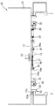
以下、本発明の実施の形態を図面に基づいて説明する。図1はリーチ式バッテリフォークリフトの概略側面図、図2は本実施の形態に係る前出し機構を取り付ける前のバッテリケースの背面図、図3は同じく底面図、図4は前出し機構を取り付けたバッテリケースの背面図、図5は同じく底面図である。
【0010】
リーチ式バッテリフォークリフトは、図1に示すように、車体1の前面下部から前方に延びる左右一対のリーチレッグ2を有している。左右のマスト3はその下端部がリーチレッグ2に沿って移動可能なマストキャリッジ3aに結合されていて、リーチシリンダ4によって前後移動、すなわちリーチ動作されるようになっている。また、車体1の前面部には、リーチレッグ2の基部側上面と、車体1の上面部から前方に張り出すフード部1aとによって形成される側面視で略コ字形のバッテリ収納部5が形成され、このバッテリ収納部5にバッテリ10が収納されている。なお、バッテリ収納部5は、左右側面にもフード部を有することもある。
【0011】
バッテリ10は、図示しない多数のバッテリセルと、そのバッテリセルを収納するための横長の箱形に形成される鉄板製のバッテリケース11とによって成立している。そして、バッテリケース11には、バッテリ10をバッテリ収納部5に固定するための必要な機能部品のほか、前出し用の機能部品、すなわちバッテリ収納部5から前方へ引き出し、かつ押し込むために必要な機能部品が直接的に設けられている。
【0012】
図4及び図5に示すように、バッテリケース11における底板11aの下面左右には、リーチレッグ2に沿って移動する左右一対のレールガイド12が設けられている。レールガイド12は、リーチレッグ2の上面を摺動するメインガイド12aと、リーチレッグ2の内側面に沿うサイドガイド12bとからなり、メインガイド12aの下面には、摺動性の高いライナー12cが固着され、引き出し、押し込み動作の円滑化を図っている。
【0013】
また、バッテリケース11における後面板の中央下部には、バッテリ10をバッテリ収納部5に固定するためのフック13が、例えば溶接にて固着されており、このフック13が車体1側に備えられるロック部材6(図5に概略的に示す)と係合することによってバッテリ10がバッテリ収納部5に固定される。
ロック部材6は、図示省略のロックバネにて係合可能位置に保持されていて、フック13先端の斜面にて押し退けられたのち、該フック13に自動的に係合する構成とされ、係合の解除は、例えば運転席に乗車した乗員のによるペダルあるいはレバー操作等のロック操作部材によって行われるようになっている。
【0014】
また、バッテリケース11における底板11aの中央下面には、バッテリ引き出し時にマスト3側に設けられる引き出し部材7と係脱可能なバッテリ引き出し用の係合ピン15が備えられている。この係合ピン15が本発明の係合部材に対応する。なお、引き出し部材7は図5においては概略的に示されているが、マストキャリッジ3a(図1参照)の水平部上面の略中央部上向きに突設された短円柱形のピンからなり、マスト3が最も引き込まれたとき、バッテリケース11の底板11aの下面に潜り込む(図5に仮想線で示す)ように相対的な位置関係が設定されている。
【0015】
引き出し用の係合ピン15は、スライドガイド16によって横方向(車幅方向)に摺動可能に案内される断面角形のバー17の略中央下面に突設(溶接)されており、該バー17の横移動によって、引き出し部材7の移動軌跡(図5に示す線P−P)に対応する係合可能位置と、移動軌跡から外れる係合不能位置との2位置に位置替え可能とされている。
なお、スライドガイド16は、底板11aの下面に溶接された4個の取付ボス11b(図2及び図3参照)と、前後の取付ボス11bの下面間に掛け渡されかつボルト18によって締着された2枚のプレート16aとによって構成されている。従って、バー17は前後の取付ボス11b間に嵌め込まれ、かつ下面をプレート16aで支えられた状態で摺動可能とされている。
【0016】
また、底板11aの下面には、係合ピン15の位置切り替え用としてのリンク19が配置され、その略中央部付近がリンクブラケット20にピン21によって水平回動可能に取り付けられている。リンクブラケット20は底板11aの下面に溶接された左右2個の取付ボス11c(図2及び図3参照)にボルト22によって締着されている。
リンク19は取付ボス11c間を通って前後方向に延びるとともに、その前端側面がバー17に設けられた突起23に係合(当接)され、後端部がバッテリケース11の後面よりも後方へ突出される。この後端突出部は、前記固定用フック13と上下方向において重なり合う位置となるように設定されている。
従って、リンク19は、図5に仮想線で示すように、固定用のフック13にロック部材6が係合されたロック状態のとき、該ロック部材6によって後端部を押されて回動するとともに、前端部によって突起23を加圧してバー17を摺動させ、係合ピン15を引き出し部材7の移動軌跡から外れる係合不能位置へ切り替える。
【0017】
また、バー17は係合ピン15を係合不能位置から係合可能位置へ切り替える方向にスプリング24にて引き寄せられている。従って、ロック部材6のフック13に対する係合が解除されたときは、バー17はスプリング24によって摺動されて係合ピン15を係合可能位置に切り替える。このとき、上記と逆方向に回動されるリンク19が一方の取付ボス11cに当接することによって係合ピン15が係合可能位置に止まる。すなわち、リンク19とスプリング24とによって係合ピン15の位置切り替え機構が構成されている。
なお、位置切り替え用のスプリング24のバネ力は、前記ロックバネのバネ力よりも小さく設定されており、従って、バッテリ10がバッテリ収納部5に収納され、ロック部材6にて固定されている通常時には、係合ピン15は係合不能位置に保持される。
【0018】
また、バッテリケース11における底板11aの下面前端部には、左右一対の押し込み用クッションラバー25がラバーブラケット26を介して取り付けられている。このクッションラバー25はバッテリ10のバッテリ収納部5への収納状態で、マストキャリッジ3aに形成された加圧部8(図5に概略的に示す)とマスト3の引き込み端で当接可能な位置に設定されている。なお、ラバーブラケット26は、図2及び図3に示すように、底板11aの下面に溶接されており、一方のラバーブラケット26は、前記位置切り替え用のスプリング24の取付ブラケットを兼用している。
【0019】
本実施の形態は上記のように構成したものである。従って、バッテリ10はバッテリ収納部5に収納された状態では、図5に仮想線で示すように、ロック部材6が固定用フック13に係合されて車体1側に固定されている。このとき、ロック部材6で押されたリンク19を介してバー17が図示右方へ移動され、係合ピン15が係合不能位置に保持されている。
従って、この状態では、マスト3が最も後端位置まで引き込まれると、引き出し部材7が係合ピンよりも後方へ移動(図5仮想線参照)するが、係合ピン15が係合不能位置に保持されているため、引き出し部材7が係合ピン15と係合することがなく、マスト3は何らの支障無くリーチ動作を行うことができる。
【0020】
一方、バッテリ10をサービス作業のためにバッテリ収納部5から前方へ引き出すときは、マスト3を最も後端位置まで引き込んだ状態で、操作部材を操作して、ロック部材6をフック13から解除すると、その解除動作と同時にロック部材6によるリンク19の規制が解放される。従って、リンク19及びバー17がスプリング24によって図5に実線で示すように移動され、係合ピン15が係合可能位置へ切り替えられる。
その後、ロック部材6の解除状態を維持しつつリーチシリンダ4を作動してマスト3を前方へ押し出すと、引き出し部材7が係合ピン15に係合し、バッテリ10を前方へ引き出す。このとき、バッテリ10はバッテリケース11の下面に設けられたレールガイド12によって横方向の動きを規制されつつリーチレッグ2に沿って移動されることになり、安定状態で前方へ引き出される。
【0021】
サービス作業後は、マスト3を引き込むと、マストキャリッジ3aの加圧部8がバッテリケース11のクッションラバー25を押し、バッテリ10をバッテリ収納部5へ収納する。
そして、バッテリ収納部5に押し込まれたとき、フック13が先端の斜面によってロック位置へ復帰しているロック部材6を押し退けて進入することにより自動的に係合し、バッテリ10が車体側に固定される。このとき、ロック部材6がリンク19を押し退け、バー17を介して係合ピン15を係合不能位置へ退避させる。かくして、初期状態に復帰される。
【0022】
このように、本実施の形態によれば、バッテリ10の引き出し、押し込みをマスト3のリーチ動作を利用して楽に行うことができ、その場合、係合ピン15の位置切り替え操作がロック部材6の解除動作に連動して行われるので、前出しのための操作性が向上する。
しかして、本実施の形態においては、バッテリ10をバッテリ収納部5に固定するに必要な部材のほか、バッテリ10のサービス作業のために、バッテリ収納部5からバッテリ10を引き出し、押し込む上で必要な部材を、それぞれバッテリケース11に直接的に備える構成としたことによって、従来であれば必要としていたバッテリトレイを省略することができた。
このことによって、バッテリ前出し装置に関しての部品点数が削減されることになり、特にバッテリトレイが大型部品であることから、コストの低減及び車両の軽量化に有効となる。
【0023】
また、本実施の形態では、バッテリケース11の底板11aの下面に、係合ピン15を有する位置切り替え用のバー17をスライドガイド16を介して摺動可能に取り付ける構造としたので、バッテリ10の引き出し負荷をバー17及びスライドガイド16によって受けることが可能となり、強度の確保が容易でかつ安定した切り替え動作を得ることができる。また、リンク19にはバッテリ10の引き出し負荷が作用することがなく、強度を考える必要がない。
【0024】
また、底板11aの下面に設けられたレールガイド12は、バッテリ10の引き出し、押し込み時の前後移動をリーチレッグ2に沿って安定的に行わせることができる。また、バッテリケース11に引き出し用として備えられる係合ピン15やリンク19等の前出し機構を、レールガイド12(詳しくは、サイドガイド12b)の突出高さの範囲内に収まるように設定してあるので、バッテリ10のバッテリケース11を床面に置いたときに、レールガイド12を下駄代わりに用いて、前記前出し機構の床面に対する干渉を回避できる。
【0025】
なお、本発明は図示の実施の形態に限定されるものではなく、その要旨を逸脱しない範囲内で適宜変更することが可能である。
例えば、係合ピン15の位置の切り替え動作が、ロック部材6のロック解除動作に連動して行われる構成としたが、切り替え操作を単独で行うように変更してもよい。
また、前出し装置を構成する主たる構成部材としての、引き出し部材7、それに対応して設定される係合ピン15等の形状については、図示の短円柱形に限らず、引き出し方向において相互に当接可能な形状であれば差し支えない。
【0026】
【発明の効果】
以上詳述したように、本発明によれば、バッテリをバッテリ収納部から引き出すための前出し装置の構成部材をバッテリケースに備えたことによって、バッテリトレイを省略してコスト低減を達成できる。
【図面の簡単な説明】
【図1】リーチ式バッテリフォークリフトの概略側面図である。
【図2】本実施の形態に係る前出し機構を取り付ける前のバッテリの背面図である。
【図3】同じく底面図である。
【図4】前出し機構を取り付けたバッテリの背面図である。
【図5】同じく底面図である。
【符号の説明】
1 車体
2 リーチレッグ
3 マスト
5 バッテリ収納部
6 ロック部材
7 引き出し部材
10 バッテリ
11 バッテリケース
11a 底板
12 レールガイド
13 固定用フック
15 係合ピン
16 スライドガイド
17 バー
19 リンク[0001]
BACKGROUND OF THE INVENTION
The present invention relates to a battery unloading device for pulling a battery forward from a battery storage portion for service work such as maintenance and inspection in a reach type battery forklift.
[0002]
[Prior art]
Conventionally, an advance device for a reach type battery forklift is disclosed in, for example, Japanese Patent Publication No. 4-55889.
The advancement device described in this publication uses a reach operation of a mast that moves forward and backward as guided by a reach leg to draw out and push in a battery mounted in a battery storage portion at the front of the vehicle body via a battery tray. It is comprised so that it can do.
In the case of the above-described advance device, the battery tray on which the battery is placed is engaged with a lock member provided on the vehicle body side and fixed at the storage position, and a drawer for hook provided on the mast side. It has a structure including a movable hook that can be attached to and detached from the pin.
[0003]
[Problems to be solved by the invention]
However, the above-described conventional apparatus has a structure in which the battery tray is provided with the components of the advance mechanism that is set to draw the battery forward from the battery housing. That is, the conventional advancement apparatus has a problem of high cost because of a structure that requires a large component for mounting a battery, called a battery tray.
[0004]
The present invention has been made in view of the above-described conventional problems, and an object of the present invention is to provide a battery advance device that can omit a battery tray in a reach type battery forklift. is there.
[0005]
[Means for Solving the Problems]
In order to achieve the above object, the advancement apparatus according to the present invention has a configuration as described in each of the claims.
Therefore, according to the first aspect of the present invention, the battery case is provided with an engaging member that engages with the mast pull-out member when the battery is pulled out from the battery housing portion using the reach operation of the mast. By this, the large component called a battery tray which was conventionally required can be omitted. For this reason, it is possible to reduce the cost by reducing the number of parts related to the battery advance device.
[0006]
Further , by providing the engaging member on the bar slidably attached to the battery case, when pulling the battery forward, the bar is slid to the position where the engaging member can be engaged with the pulling member. The pulling operation can be performed by switching, and at the time of the cargo handling operation, the reach operation of the mast can be performed without any trouble by switching the engaging member to the non-engageable position. In addition, since the battery pull-out load can be received by the bar and the slide guide, the strength can be easily secured and a stable switching operation can be obtained.
[0007]
In addition , since the engagement member is moved from the non-engageable position to the engageable position via the link in conjunction with the unlocking operation by the lock member, the operation of switching the position of the engagement member is simplified. Operability can be improved. In addition, since the battery pull-out load does not act on the link, the link can be reduced in size.
[0008]
According to the second aspect of the present invention, since the rail guide is provided, the battery pulling-out operation can be stably performed along the reach leg. Also, as fall within the scope of the protrusion height of the rail guide of the side guide, the Rukoto is advancing mechanism settings such engagement members or links, when placing the battery case on the floor, the rail guide (more Can avoid interference with the floor surface of the advance mechanism by using side guides instead of clogs.
[0009]
DETAILED DESCRIPTION OF THE INVENTION
Hereinafter, embodiments of the present invention will be described with reference to the drawings. FIG. 1 is a schematic side view of a reach-type battery forklift, FIG. 2 is a rear view of a battery case before attaching a advancement mechanism according to the present embodiment, FIG. 3 is a bottom view, and FIG. 4 is attached with an advancement mechanism. FIG. 5 is a bottom view of the battery case.
[0010]
As shown in FIG. 1, the reach type battery forklift has a pair of left and
[0011]
The
[0012]
As shown in FIGS. 4 and 5, a pair of left and
[0013]
In addition, a
The lock member 6 is held in an engageable position by a lock spring (not shown), and is configured to automatically engage with the
[0014]
The
[0015]
The pull-out
The
[0016]
Further, a
The
Accordingly, the
[0017]
The
Note that the spring force of the
[0018]
In addition, a pair of left and right push-in
[0019]
This embodiment is configured as described above. Therefore, in a state where the
Therefore, in this state, when the
[0020]
On the other hand, when the
Thereafter, when the reach cylinder 4 is operated and the
[0021]
After the service work, when the
When the
[0022]
As described above, according to the present embodiment, the
Thus, in the present embodiment, in addition to the members necessary to fix the
As a result, the number of parts related to the battery advancement device is reduced. Particularly, since the battery tray is a large-sized part, it is effective in reducing the cost and reducing the weight of the vehicle.
[0023]
In the present embodiment, since the
[0024]
The
[0025]
In addition, this invention is not limited to embodiment of illustration, It can change suitably in the range which does not deviate from the summary.
For example, although the switching operation of the position of the
In addition, the shapes of the pull-out member 7 and the
[0026]
【The invention's effect】
As described above in detail, according to the present invention, by providing the battery case with the constituent members of the advance device for pulling out the battery from the battery housing portion, it is possible to reduce the cost by omitting the battery tray.
[Brief description of the drawings]
FIG. 1 is a schematic side view of a reach type battery forklift.
FIG. 2 is a rear view of the battery before the advancement mechanism according to the present embodiment is attached.
FIG. 3 is a bottom view of the same.
FIG. 4 is a rear view of a battery to which a advancement mechanism is attached.
FIG. 5 is a bottom view of the same.
[Explanation of symbols]
DESCRIPTION OF
Claims (2)
前記バッテリのバッテリケース外面に、前記バッテリ収納部の前方で前後方向に移動するマストに設けられた引き出し部材と係脱可能な係合部材を備え、
前記係合部材は、前記バッテリケースの底板下面にスライドガイドを介して車幅方向に摺動可能に取り付けられたバーに設けられ、該バーを摺動することによって前記引き出し部材に対する係合可能位置と係合不能位置とに切り替え可能とされ、
前記バーが前記バッテリケースに回動可能に取り付けられたリンクと連携されており、そのリンクは、前記バッテリをバッテリ収納部に固定するために備えられているロック部材のロック解除動作に連動して前記係合部材を係合不能位置から係合可能位置に切り替えるように構成されている
バッテリ前出し装置。A battery unwinding device that is provided in a reach type battery forklift and draws out the battery stored in the battery storage set in the vehicle body,
On the outer surface of the battery case of the battery, provided with an engaging member detachable from a drawer member provided on a mast that moves in the front-rear direction in front of the battery housing portion ,
The engagement member is provided on a bar attached to the bottom surface of the bottom plate of the battery case via a slide guide so as to be slidable in the vehicle width direction, and the engagement member can be engaged with the drawer member by sliding the bar. And can be switched to a non-engageable position,
The bar is linked to a link pivotally attached to the battery case, and the link is linked to an unlocking operation of a lock member provided to fix the battery to the battery housing. A battery advancement device configured to switch the engagement member from an unengageable position to an engageable position .
前記バッテリケースの下面には、前記マストの前後移動を案内するリーチレッグに沿って移動可能なレールガイドを備え、
前記レールガイドは、前記リーチレッグの上面を摺動するメインガイドと、前記リーチレッグの内側面に沿うサイドガイドとからなり、
前記係合部材やリンク等の前出し機構が、前記レールガイドのサイドガイドの突出高さの範囲内に収まるように設定されている
バッテリ前出し装置。The battery advancement device according to claim 1,
The lower surface of the battery case includes a rail guide that can move along a reach leg that guides the mast to move back and forth.
The rail guide consists of a main guide that slides on the upper surface of the reach leg, and a side guide that runs along the inner surface of the reach leg.
A battery advancement device in which advancement mechanisms such as the engaging member and the link are set so as to be within a protruding height range of a side guide of the rail guide .
Priority Applications (1)
| Application Number | Priority Date | Filing Date | Title |
|---|---|---|---|
| JP2000186703A JP3772647B2 (en) | 2000-06-21 | 2000-06-21 | Battery advance device |
Applications Claiming Priority (1)
| Application Number | Priority Date | Filing Date | Title |
|---|---|---|---|
| JP2000186703A JP3772647B2 (en) | 2000-06-21 | 2000-06-21 | Battery advance device |
Publications (2)
| Publication Number | Publication Date |
|---|---|
| JP2002003194A JP2002003194A (en) | 2002-01-09 |
| JP3772647B2 true JP3772647B2 (en) | 2006-05-10 |
Family
ID=18686815
Family Applications (1)
| Application Number | Title | Priority Date | Filing Date |
|---|---|---|---|
| JP2000186703A Expired - Fee Related JP3772647B2 (en) | 2000-06-21 | 2000-06-21 | Battery advance device |
Country Status (1)
| Country | Link |
|---|---|
| JP (1) | JP3772647B2 (en) |
Cited By (1)
| Publication number | Priority date | Publication date | Assignee | Title |
|---|---|---|---|---|
| CN105502225A (en) * | 2016-01-22 | 2016-04-20 | 安徽江淮银联重型工程机械有限公司 | Storage battery drag-out mechanism of forklift truck |
Families Citing this family (4)
| Publication number | Priority date | Publication date | Assignee | Title |
|---|---|---|---|---|
| CN110143544A (en) * | 2019-06-20 | 2019-08-20 | 杭叉集团股份有限公司 | A kind of reach truck battery mobile device |
| US12391107B2 (en) | 2021-10-22 | 2025-08-19 | Crown Equipment Corporation | Battery guide pins for a battery receiving space of a materials handling vehicle, and materials handling vehicles incorporating the same |
| WO2023184215A1 (en) * | 2022-03-30 | 2023-10-05 | Crown Equipment Corporation | Battery guide pins for a battery receiving space of a materials handling vehicle, and materials handling vehicles incorporating the same |
| CN116039573B (en) * | 2023-01-29 | 2023-10-20 | 机科发展科技股份有限公司 | Automatic battery replacing device |
-
2000
- 2000-06-21 JP JP2000186703A patent/JP3772647B2/en not_active Expired - Fee Related
Cited By (1)
| Publication number | Priority date | Publication date | Assignee | Title |
|---|---|---|---|---|
| CN105502225A (en) * | 2016-01-22 | 2016-04-20 | 安徽江淮银联重型工程机械有限公司 | Storage battery drag-out mechanism of forklift truck |
Also Published As
| Publication number | Publication date |
|---|---|
| JP2002003194A (en) | 2002-01-09 |
Similar Documents
| Publication | Publication Date | Title |
|---|---|---|
| JP5193555B2 (en) | Vehicle storage seat | |
| KR101194914B1 (en) | Mono leg transformer seat | |
| EP2117873B1 (en) | Housing system and housing method for passenger seat | |
| JP5398336B2 (en) | Vehicle seat locking device | |
| KR100999795B1 (en) | Flow containment sheet assembly with major lateral displacement | |
| JP2012035655A (en) | Seat slide apparatus for vehicle | |
| JP4583613B2 (en) | Vehicle seat support mechanism | |
| JP3772647B2 (en) | Battery advance device | |
| JP5844127B2 (en) | Vehicle seat | |
| JP2018034801A (en) | Vehicle seat | |
| JP6244847B2 (en) | Vehicle seat device | |
| CA2696407A1 (en) | Vehicle seat apparatus | |
| JP2007050822A (en) | Motorcycle seat height changing device and motorcycle | |
| JPS62194955A (en) | Console box for automobile | |
| JP2001026949A (en) | Arm rest in driver's seat part | |
| JP3014941B2 (en) | Seat slide device for vehicle seat | |
| JP2002337576A (en) | Slide seat of vehicle | |
| JP2008273399A (en) | Cargo board interlocking structure | |
| JP7801565B2 (en) | Vehicle seats | |
| US12145486B2 (en) | Stowable seat assemblies and vehicles including same | |
| JP2025034899A (en) | Seating device | |
| JP6456107B2 (en) | Vehicle seat | |
| JP2004182147A (en) | Laterally jump-housing type slide seat | |
| JP5393437B2 (en) | Sheet device | |
| JPH057876Y2 (en) |
Legal Events
| Date | Code | Title | Description |
|---|---|---|---|
| A977 | Report on retrieval |
Free format text: JAPANESE INTERMEDIATE CODE: A971007 Effective date: 20051025 |
|
| A131 | Notification of reasons for refusal |
Free format text: JAPANESE INTERMEDIATE CODE: A131 Effective date: 20051108 |
|
| A521 | Written amendment |
Free format text: JAPANESE INTERMEDIATE CODE: A523 Effective date: 20051130 |
|
| TRDD | Decision of grant or rejection written | ||
| A01 | Written decision to grant a patent or to grant a registration (utility model) |
Free format text: JAPANESE INTERMEDIATE CODE: A01 Effective date: 20060124 |
|
| A61 | First payment of annual fees (during grant procedure) |
Free format text: JAPANESE INTERMEDIATE CODE: A61 Effective date: 20060206 |
|
| FPAY | Renewal fee payment (event date is renewal date of database) |
Free format text: PAYMENT UNTIL: 20120224 Year of fee payment: 6 |
|
| FPAY | Renewal fee payment (event date is renewal date of database) |
Free format text: PAYMENT UNTIL: 20120224 Year of fee payment: 6 |
|
| FPAY | Renewal fee payment (event date is renewal date of database) |
Free format text: PAYMENT UNTIL: 20130224 Year of fee payment: 7 |
|
| FPAY | Renewal fee payment (event date is renewal date of database) |
Free format text: PAYMENT UNTIL: 20140224 Year of fee payment: 8 |
|
| LAPS | Cancellation because of no payment of annual fees |