JP3766425B2 - Image generating apparatus, load display method, and program - Google Patents
Image generating apparatus, load display method, and program Download PDFInfo
- Publication number
- JP3766425B2 JP3766425B2 JP2004257260A JP2004257260A JP3766425B2 JP 3766425 B2 JP3766425 B2 JP 3766425B2 JP 2004257260 A JP2004257260 A JP 2004257260A JP 2004257260 A JP2004257260 A JP 2004257260A JP 3766425 B2 JP3766425 B2 JP 3766425B2
- Authority
- JP
- Japan
- Prior art keywords
- image
- unit
- tire
- load
- virtual vehicle
- Prior art date
- Legal status (The legal status is an assumption and is not a legal conclusion. Google has not performed a legal analysis and makes no representation as to the accuracy of the status listed.)
- Expired - Fee Related
Links
Images


Classifications
-
- G—PHYSICS
- G09—EDUCATION; CRYPTOGRAPHY; DISPLAY; ADVERTISING; SEALS
- G09B—EDUCATIONAL OR DEMONSTRATION APPLIANCES; APPLIANCES FOR TEACHING, OR COMMUNICATING WITH, THE BLIND, DEAF OR MUTE; MODELS; PLANETARIA; GLOBES; MAPS; DIAGRAMS
- G09B9/00—Simulators for teaching or training purposes
- G09B9/02—Simulators for teaching or training purposes for teaching control of vehicles or other craft
- G09B9/04—Simulators for teaching or training purposes for teaching control of vehicles or other craft for teaching control of land vehicles
- G09B9/05—Simulators for teaching or training purposes for teaching control of vehicles or other craft for teaching control of land vehicles the view from a vehicle being simulated
-
- A—HUMAN NECESSITIES
- A63—SPORTS; GAMES; AMUSEMENTS
- A63F—CARD, BOARD, OR ROULETTE GAMES; INDOOR GAMES USING SMALL MOVING PLAYING BODIES; VIDEO GAMES; GAMES NOT OTHERWISE PROVIDED FOR
- A63F13/00—Video games, i.e. games using an electronically generated display having two or more dimensions
- A63F13/50—Controlling the output signals based on the game progress
- A63F13/52—Controlling the output signals based on the game progress involving aspects of the displayed game scene
-
- A—HUMAN NECESSITIES
- A63—SPORTS; GAMES; AMUSEMENTS
- A63F—CARD, BOARD, OR ROULETTE GAMES; INDOOR GAMES USING SMALL MOVING PLAYING BODIES; VIDEO GAMES; GAMES NOT OTHERWISE PROVIDED FOR
- A63F13/00—Video games, i.e. games using an electronically generated display having two or more dimensions
-
- A—HUMAN NECESSITIES
- A63—SPORTS; GAMES; AMUSEMENTS
- A63F—CARD, BOARD, OR ROULETTE GAMES; INDOOR GAMES USING SMALL MOVING PLAYING BODIES; VIDEO GAMES; GAMES NOT OTHERWISE PROVIDED FOR
- A63F13/00—Video games, i.e. games using an electronically generated display having two or more dimensions
- A63F13/50—Controlling the output signals based on the game progress
- A63F13/53—Controlling the output signals based on the game progress involving additional visual information provided to the game scene, e.g. by overlay to simulate a head-up display [HUD] or displaying a laser sight in a shooting game
- A63F13/537—Controlling the output signals based on the game progress involving additional visual information provided to the game scene, e.g. by overlay to simulate a head-up display [HUD] or displaying a laser sight in a shooting game using indicators, e.g. showing the condition of a game character on screen
-
- A—HUMAN NECESSITIES
- A63—SPORTS; GAMES; AMUSEMENTS
- A63F—CARD, BOARD, OR ROULETTE GAMES; INDOOR GAMES USING SMALL MOVING PLAYING BODIES; VIDEO GAMES; GAMES NOT OTHERWISE PROVIDED FOR
- A63F13/00—Video games, i.e. games using an electronically generated display having two or more dimensions
- A63F13/55—Controlling game characters or game objects based on the game progress
- A63F13/56—Computing the motion of game characters with respect to other game characters, game objects or elements of the game scene, e.g. for simulating the behaviour of a group of virtual soldiers or for path finding
-
- A—HUMAN NECESSITIES
- A63—SPORTS; GAMES; AMUSEMENTS
- A63F—CARD, BOARD, OR ROULETTE GAMES; INDOOR GAMES USING SMALL MOVING PLAYING BODIES; VIDEO GAMES; GAMES NOT OTHERWISE PROVIDED FOR
- A63F13/00—Video games, i.e. games using an electronically generated display having two or more dimensions
- A63F13/55—Controlling game characters or game objects based on the game progress
- A63F13/57—Simulating properties, behaviour or motion of objects in the game world, e.g. computing tyre load in a car race game
-
- A—HUMAN NECESSITIES
- A63—SPORTS; GAMES; AMUSEMENTS
- A63F—CARD, BOARD, OR ROULETTE GAMES; INDOOR GAMES USING SMALL MOVING PLAYING BODIES; VIDEO GAMES; GAMES NOT OTHERWISE PROVIDED FOR
- A63F13/00—Video games, i.e. games using an electronically generated display having two or more dimensions
- A63F13/60—Generating or modifying game content before or while executing the game program, e.g. authoring tools specially adapted for game development or game-integrated level editor
-
- A—HUMAN NECESSITIES
- A63—SPORTS; GAMES; AMUSEMENTS
- A63F—CARD, BOARD, OR ROULETTE GAMES; INDOOR GAMES USING SMALL MOVING PLAYING BODIES; VIDEO GAMES; GAMES NOT OTHERWISE PROVIDED FOR
- A63F13/00—Video games, i.e. games using an electronically generated display having two or more dimensions
- A63F13/80—Special adaptations for executing a specific game genre or game mode
- A63F13/803—Driving vehicles or craft, e.g. cars, airplanes, ships, robots or tanks
-
- G—PHYSICS
- G09—EDUCATION; CRYPTOGRAPHY; DISPLAY; ADVERTISING; SEALS
- G09B—EDUCATIONAL OR DEMONSTRATION APPLIANCES; APPLIANCES FOR TEACHING, OR COMMUNICATING WITH, THE BLIND, DEAF OR MUTE; MODELS; PLANETARIA; GLOBES; MAPS; DIAGRAMS
- G09B9/00—Simulators for teaching or training purposes
- G09B9/02—Simulators for teaching or training purposes for teaching control of vehicles or other craft
- G09B9/04—Simulators for teaching or training purposes for teaching control of vehicles or other craft for teaching control of land vehicles
-
- A—HUMAN NECESSITIES
- A63—SPORTS; GAMES; AMUSEMENTS
- A63F—CARD, BOARD, OR ROULETTE GAMES; INDOOR GAMES USING SMALL MOVING PLAYING BODIES; VIDEO GAMES; GAMES NOT OTHERWISE PROVIDED FOR
- A63F2300/00—Features of games using an electronically generated display having two or more dimensions, e.g. on a television screen, showing representations related to the game
- A63F2300/30—Features of games using an electronically generated display having two or more dimensions, e.g. on a television screen, showing representations related to the game characterized by output arrangements for receiving control signals generated by the game device
- A63F2300/303—Features of games using an electronically generated display having two or more dimensions, e.g. on a television screen, showing representations related to the game characterized by output arrangements for receiving control signals generated by the game device for displaying additional data, e.g. simulating a Head Up Display
-
- A—HUMAN NECESSITIES
- A63—SPORTS; GAMES; AMUSEMENTS
- A63F—CARD, BOARD, OR ROULETTE GAMES; INDOOR GAMES USING SMALL MOVING PLAYING BODIES; VIDEO GAMES; GAMES NOT OTHERWISE PROVIDED FOR
- A63F2300/00—Features of games using an electronically generated display having two or more dimensions, e.g. on a television screen, showing representations related to the game
- A63F2300/30—Features of games using an electronically generated display having two or more dimensions, e.g. on a television screen, showing representations related to the game characterized by output arrangements for receiving control signals generated by the game device
- A63F2300/308—Details of the user interface
-
- A—HUMAN NECESSITIES
- A63—SPORTS; GAMES; AMUSEMENTS
- A63F—CARD, BOARD, OR ROULETTE GAMES; INDOOR GAMES USING SMALL MOVING PLAYING BODIES; VIDEO GAMES; GAMES NOT OTHERWISE PROVIDED FOR
- A63F2300/00—Features of games using an electronically generated display having two or more dimensions, e.g. on a television screen, showing representations related to the game
- A63F2300/60—Methods for processing data by generating or executing the game program
- A63F2300/6009—Methods for processing data by generating or executing the game program for importing or creating game content, e.g. authoring tools during game development, adapting content to different platforms, use of a scripting language to create content
-
- A—HUMAN NECESSITIES
- A63—SPORTS; GAMES; AMUSEMENTS
- A63F—CARD, BOARD, OR ROULETTE GAMES; INDOOR GAMES USING SMALL MOVING PLAYING BODIES; VIDEO GAMES; GAMES NOT OTHERWISE PROVIDED FOR
- A63F2300/00—Features of games using an electronically generated display having two or more dimensions, e.g. on a television screen, showing representations related to the game
- A63F2300/60—Methods for processing data by generating or executing the game program
- A63F2300/64—Methods for processing data by generating or executing the game program for computing dynamical parameters of game objects, e.g. motion determination or computation of frictional forces for a virtual car
-
- A—HUMAN NECESSITIES
- A63—SPORTS; GAMES; AMUSEMENTS
- A63F—CARD, BOARD, OR ROULETTE GAMES; INDOOR GAMES USING SMALL MOVING PLAYING BODIES; VIDEO GAMES; GAMES NOT OTHERWISE PROVIDED FOR
- A63F2300/00—Features of games using an electronically generated display having two or more dimensions, e.g. on a television screen, showing representations related to the game
- A63F2300/60—Methods for processing data by generating or executing the game program
- A63F2300/66—Methods for processing data by generating or executing the game program for rendering three dimensional images
- A63F2300/6607—Methods for processing data by generating or executing the game program for rendering three dimensional images for animating game characters, e.g. skeleton kinematics
-
- A—HUMAN NECESSITIES
- A63—SPORTS; GAMES; AMUSEMENTS
- A63F—CARD, BOARD, OR ROULETTE GAMES; INDOOR GAMES USING SMALL MOVING PLAYING BODIES; VIDEO GAMES; GAMES NOT OTHERWISE PROVIDED FOR
- A63F2300/00—Features of games using an electronically generated display having two or more dimensions, e.g. on a television screen, showing representations related to the game
- A63F2300/80—Features of games using an electronically generated display having two or more dimensions, e.g. on a television screen, showing representations related to the game specially adapted for executing a specific type of game
- A63F2300/8017—Driving on land or water; Flying
Landscapes
- Engineering & Computer Science (AREA)
- Multimedia (AREA)
- Theoretical Computer Science (AREA)
- Human Computer Interaction (AREA)
- Physics & Mathematics (AREA)
- Aviation & Aerospace Engineering (AREA)
- Business, Economics & Management (AREA)
- Educational Administration (AREA)
- Educational Technology (AREA)
- General Physics & Mathematics (AREA)
- Optics & Photonics (AREA)
- Processing Or Creating Images (AREA)
Description
本発明は、画像生成装置、荷重表示方法、ならびに、プログラムに関する。 The present invention relates to an image generation device, a load display method, and a program.
従来より、業務用や家庭用のゲーム装置が広く普及している。このようなゲーム装置では、一例として、自動車等の乗り物によるレースゲームを楽しむことができる。
このようなレースゲームは、たとえば、利用者(プレイヤ)が、コントローラ等を操作して、仮想空間内を走行する仮想車両(F1マシンや市販車等)を所定のゴール地点まで運転し、所要時間や他の仮想車両との先後着を競うものが一般的である。
Conventionally, game machines for business use and home use have been widely used. In such a game device, for example, a racing game by a vehicle such as an automobile can be enjoyed.
In such a race game, for example, a user (player) operates a controller or the like to drive a virtual vehicle (F1 machine, commercial vehicle, etc.) traveling in a virtual space to a predetermined goal point, and the required time. It is common to compete for first and last arrivals with other virtual vehicles.
また、ゲーム操作に不慣れな利用者でも比較的簡単な操作でレースゲームを楽しむことのできる競争ゲーム装置の技術も開示されている(たとえば、特許文献1参照)。
しかしながら、レースゲームを楽しめる従来のゲーム装置では、プレイ中に仮想車両の挙動を十分に把握できない場合が多かった。
つまり、現実の車両であれば、加速時や減速時等には、慣性力が働くため、ドライバ等は、後ろ向きの荷重や前向きの荷重を体感することになる。また、コーナ等の旋回時には、遠心力が働くため、旋回方向と逆向きの荷重を体感することになる。このような荷重の体感により、ドライバ等は、車両の挙動や走行状況を容易に把握することがきる。
これに対し、レースゲームのプレイ中には、表示される映像から何らの荷重も体感できないため、利用者は、仮想車両の挙動を十分に把握することができないという問題があった。
However, in conventional game devices that can enjoy a racing game, there are many cases where the behavior of the virtual vehicle cannot be sufficiently grasped during play.
That is, in an actual vehicle, an inertial force works during acceleration or deceleration, so that the driver or the like feels a backward load or a forward load. Moreover, since centrifugal force works when turning corners or the like, a load opposite to the turning direction is experienced. By such a bodily sensation of the load, the driver or the like can easily grasp the behavior of the vehicle and the traveling state.
On the other hand, there is a problem that the user cannot fully understand the behavior of the virtual vehicle because no load can be experienced from the displayed image during the race game.
本発明は、このような課題を解決するためになされたもので、走行状況に応じた荷重を適切に視覚化することにより、仮想車両の挙動を容易に把握することのできる画像生成装置、荷重表示方法、ならびに、これらをコンピュータによって実現するプログラムを提供することを目的とする。 The present invention has been made in order to solve such a problem, and an image generating apparatus and a load that can easily grasp the behavior of a virtual vehicle by appropriately visualizing a load according to a traveling situation It is an object of the present invention to provide a display method and a program for realizing these by a computer.
本発明の第1の観点に係る画像生成装置は、操作入力受付部、前方画像生成部、タイヤ画像生成部、および、表示制御部を備え、以下のように構成する。 An image generation apparatus according to a first aspect of the present invention includes an operation input reception unit, a front image generation unit, a tire image generation unit, and a display control unit, and is configured as follows.
まず、操作入力受付部は、仮想空間内を走行させる仮想車両に向けた操作入力を受け付ける。また、前方画像生成部は、受け付けられた操作入力に応じて走行する仮想車両の前方画像(たとえば、ドライバーズ・ビュー等)を生成する。
一方、タイヤ画像生成部は、当該仮想車両の走行状況に基づく荷重に応じて、形状の異なるタイヤ画像を生成する。そして、表示制御部は、生成された当該前方画像と当該タイヤ画像とを合成して表示する。
これにより、仮想車両の走行状況に基づく荷重に応じてタイヤ画像の形状が変化するため、利用者は、そのタイヤ画像から仮想車両に加わる荷重を体感することになる。この結果、走行状況に応じた荷重を適切に視覚化することにより、仮想車両の挙動を容易に把握することができる。
First, the operation input reception unit receives an operation input directed to a virtual vehicle that travels in the virtual space. Further, the front image generation unit generates a front image (for example, a driver's view) of the virtual vehicle that travels according to the received operation input.
On the other hand, the tire image generation unit generates tire images having different shapes in accordance with the load based on the traveling state of the virtual vehicle. Then, the display control unit synthesizes and displays the generated front image and the tire image.
Thereby, since the shape of a tire image changes according to the load based on the driving | running | working condition of a virtual vehicle, a user will experience the load added to a virtual vehicle from the tire image. As a result, it is possible to easily grasp the behavior of the virtual vehicle by appropriately visualizing the load according to the traveling state.
また、前記タイヤ画像生成部は、当該荷重に応じて、縦幅または横幅の異なる平面のタイヤ画像を生成してもよい。
一例として、タイヤ画像生成部は、走行状況が減速中であれば、左右の前輪の縦幅を拡大させ、また、走行状況が左/右旋回状況であれば、右/左の前後輪の横幅を拡大させる。
つまり、走行状況に基づく荷重に応じて、タイヤ画像の縦幅または横幅が変化するため、利用者は、そのタイヤ画像から仮想車両に加わる荷重を体感することになる。この結果、走行状況に応じた荷重を適切に視覚化することにより、仮想車両の挙動を容易に把握することができる。
The tire image generation unit may generate tire images of planes having different vertical widths or horizontal widths according to the load.
As an example, the tire image generation unit enlarges the vertical width of the left and right front wheels if the driving situation is decelerating, and if the driving situation is a left / right turning situation, Increase the width.
In other words, since the vertical width or the horizontal width of the tire image changes according to the load based on the traveling state, the user can experience the load applied to the virtual vehicle from the tire image. As a result, it is possible to easily grasp the behavior of the virtual vehicle by appropriately visualizing the load according to the traveling state.
本発明の第2の観点に係る画像生成装置は、画像情報記憶部、操作入力受付部、走行状況管理部、前方画像生成部、荷重算定部、タイヤ画像生成部、および、表示制御部を備え、以下のように構成する。 An image generation apparatus according to a second aspect of the present invention includes an image information storage unit, an operation input reception unit, a traveling state management unit, a front image generation unit, a load calculation unit, a tire image generation unit, and a display control unit. The configuration is as follows.
まず、画像情報記憶部は、仮想空間内に配置される風景画像を含む画像情報を記憶する。また、操作入力受付部は、仮想空間内を走行させる仮想車両に向けた操作入力を受け付ける。また、走行状況管理部は、受け付けられた操作入力に基づいて、当該仮想車両の走行状況を管理する。そして、前方画像生成部は、記憶された当該画像情報および管理されている当該走行状況に基づいて、当該仮想車両の前方画像(たとえば、ドライバーズ・ビュー等)を生成する。
一方、荷重算定部は、管理される当該走行状況に基づいて、当該仮想車両に加わる荷重を算定する。また、タイヤ画像生成部は、算定された当該荷重に応じて、形状の異なるタイヤ画像を生成する。そして、表示制御部は、生成された当該前方画像と当該タイヤ画像とを合成して表示する。
これにより、仮想車両の走行状況に基づく荷重に応じてタイヤ画像の形状が変化するため、利用者は、そのタイヤ画像から仮想車両に加わる荷重を体感することになる。この結果、走行状況に応じた荷重を適切に視覚化することにより、仮想車両の挙動を容易に把握することができる。
First, the image information storage unit stores image information including a landscape image arranged in the virtual space. The operation input receiving unit receives an operation input directed to a virtual vehicle that travels in the virtual space. Further, the traveling state management unit manages the traveling state of the virtual vehicle based on the received operation input. Then, the front image generation unit generates a front image (for example, a driver's view) of the virtual vehicle based on the stored image information and the managed traveling state.
On the other hand, the load calculation unit calculates a load applied to the virtual vehicle based on the traveling state to be managed. The tire image generation unit generates tire images having different shapes according to the calculated load. Then, the display control unit synthesizes and displays the generated front image and the tire image.
Thereby, since the shape of a tire image changes according to the load based on the driving | running | working condition of a virtual vehicle, a user will experience the load added to a virtual vehicle from the tire image. As a result, it is possible to easily grasp the behavior of the virtual vehicle by appropriately visualizing the load according to the traveling state.
また、前記荷重算定部は、当該走行状況が加減速の場合に、慣性力により生じた当該仮想車両に加わる荷重を算定し、当該走行状況が旋回の場合に、遠心力により生じた当該仮想車両に加わる荷重を算定し、前記タイヤ画像生成部は、算定された当該荷重に応じて、縦幅または横幅の異なる平面のタイヤ画像を生成してもよい。
一例として、タイヤ画像生成部は、走行状況が減速中であれば、左右の前輪の縦幅を拡大させ、また、走行状況が左/右旋回状況であれば、右/左の前後輪の横幅を拡大させる。
つまり、走行状況に基づく荷重に応じて、タイヤ画像の縦幅または横幅が変化するため、利用者は、そのタイヤ画像から仮想車両に加わる荷重を体感することになる。この結果、走行状況に応じた荷重を適切に視覚化することにより、仮想車両の挙動を容易に把握することができる。
The load calculating unit calculates a load applied to the virtual vehicle caused by an inertial force when the traveling state is acceleration / deceleration, and the virtual vehicle caused by a centrifugal force when the traveling state is turning. The tire image generation unit may generate a tire image of a plane having a different vertical width or horizontal width according to the calculated load.
As an example, the tire image generation unit enlarges the vertical width of the left and right front wheels if the driving situation is decelerating, and if the driving situation is a left / right turning situation, Increase the width.
In other words, since the vertical width or the horizontal width of the tire image changes according to the load based on the traveling state, the user can experience the load applied to the virtual vehicle from the tire image. As a result, it is possible to easily grasp the behavior of the virtual vehicle by appropriately visualizing the load according to the traveling state.
また、当該荷重に基づいて形状の異なるマスク画像を生成するマスク画像生成部を、さらに備え、前記表示制御部は、生成された当該前方画像と当該マスク画像とを合成した後に、さらに当該タイヤ画像を合成してもよい。
この場合、走行状況に基づく荷重に応じて前方画面の表示形態も変更されるため、利用者は、この前方画面からも荷重を体感できる。
Further, the image processing apparatus further includes a mask image generation unit that generates a mask image having a different shape based on the load, and the display control unit further combines the generated front image and the mask image, and then further adds the tire image. May be synthesized.
In this case, since the display form of the front screen is also changed according to the load based on the traveling state, the user can experience the load from the front screen.
本発明の第3の観点に係る荷重表示方法は、画像情報記憶部(仮想空間内に配置される風景画像を含む画像情報を記憶する)を用いる荷重表示方法であって、操作入力受付工程、前方画像生成工程、タイヤ画像生成工程、および、表示制御工程を備え、以下のように構成する。 A load display method according to a third aspect of the present invention is a load display method using an image information storage unit (stores image information including a landscape image arranged in a virtual space), and includes an operation input receiving step, A front image generation process, a tire image generation process, and a display control process are provided and configured as follows.
まず、操作入力受付工程では、仮想空間内を走行させる仮想車両に向けた操作入力を受け付ける。また、前方画像生成工程では、受け付けられた当該操作入力に応じて走行する当該仮想車両の前方画像(たとえば、ドライバーズ・ビュー等)を、記憶された当該画像情報に基づいて生成する。
一方、タイヤ画像生成工程は、当該仮想車両の走行状況に基づく荷重に応じて、形状の異なるタイヤ画像を生成する。そして、表示制御工程は、生成された当該前方画像と当該タイヤ画像とを所定の表示装置に合成して表示する。
これにより、仮想車両の走行状況に基づく荷重に応じてタイヤ画像の形状が変化するため、利用者は、そのタイヤ画像から仮想車両に加わる荷重を体感することになる。この結果、走行状況に応じた荷重を適切に視覚化することにより、仮想車両の挙動を容易に把握することができる。
First, in the operation input receiving step, an operation input directed to a virtual vehicle traveling in the virtual space is received. In the front image generation step, a front image (for example, a driver's view) of the virtual vehicle that travels according to the received operation input is generated based on the stored image information.
On the other hand, in the tire image generation step, tire images having different shapes are generated according to the load based on the traveling state of the virtual vehicle. In the display control step, the generated front image and the tire image are combined and displayed on a predetermined display device.
Thereby, since the shape of a tire image changes according to the load based on the driving | running | working condition of a virtual vehicle, a user will experience the load added to a virtual vehicle from the tire image. As a result, it is possible to easily grasp the behavior of the virtual vehicle by appropriately visualizing the load according to the traveling state.
本発明の第4の観点に係る荷重表示方法は、画像情報記憶部(仮想空間内に配置される風景画像を含む画像情報を記憶する)を用いる荷重表示方法であって、操作入力受付工程、走行状況管理工程、前方画像生成工程、荷重算定工程、タイヤ画像生成工程、および、表示制御工程を備え、以下のように構成する。 A load display method according to a fourth aspect of the present invention is a load display method using an image information storage unit (stores image information including a landscape image arranged in a virtual space), an operation input receiving step, A traveling state management process, a front image generation process, a load calculation process, a tire image generation process, and a display control process are provided and configured as follows.
まず、操作入力受付工程では、仮想空間内を走行させる仮想車両に向けた操作入力を受け付ける。また、走行状況管理工程では、受け付けられた当該操作入力に基づいて、当該仮想車両の走行状況を管理する。そして、前方画像生成工程では、記憶された当該画像情報および管理されている当該走行状況に基づいて、当該仮想車両の前方画像(たとえば、ドライバーズ・ビュー等)を生成する。
一方、荷重算定工程では、管理される当該走行状況に基づいて、当該仮想車両に加わる荷重を算定する。また、タイヤ画像生成工程では、算定された当該荷重に応じて、形状の異なるタイヤ画像を生成する。そして、表示制御工程では、生成された当該前方画像と当該タイヤ画像とを合成して表示する。
これにより、仮想車両の走行状況に基づく荷重に応じてタイヤ画像の形状が変化するため、利用者は、そのタイヤ画像から仮想車両に加わる荷重を体感することになる。この結果、走行状況に応じた荷重を適切に視覚化することにより、仮想車両の挙動を容易に把握することができる。
First, in the operation input receiving step, an operation input directed to a virtual vehicle traveling in the virtual space is received. In the travel status management process, the travel status of the virtual vehicle is managed based on the received operation input. Then, in the front image generation step, a front image (for example, a driver's view) of the virtual vehicle is generated based on the stored image information and the managed traveling state.
On the other hand, in the load calculation step, a load applied to the virtual vehicle is calculated based on the traveling state to be managed. In the tire image generation step, tire images having different shapes are generated according to the calculated load. In the display control step, the generated front image and the tire image are combined and displayed.
Thereby, since the shape of a tire image changes according to the load based on the driving | running | working condition of a virtual vehicle, a user will experience the load added to a virtual vehicle from the tire image. As a result, it is possible to easily grasp the behavior of the virtual vehicle by appropriately visualizing the load according to the traveling state.
本発明の第5の観点に係るプログラムは、コンピュータ(ゲーム装置を含む。)を、上記の画像生成装置として機能させるように構成する。 A program according to a fifth aspect of the present invention is configured to cause a computer (including a game device) to function as the above-described image generation device.
このプログラムは、コンパクトディスク、フレキシブルディスク、ハードディスク、光磁気ディスク、ディジタルビデオディスク、磁気テープ、半導体メモリ等のコンピュータ読取可能な情報記録媒体に記録することができる。 This program can be recorded on a computer-readable information recording medium such as a compact disk, flexible disk, hard disk, magneto-optical disk, digital video disk, magnetic tape, and semiconductor memory.
上記プログラムは、当該プログラムが実行されるコンピュータとは独立して、コンピュータ通信網を介して配布・販売することができる。また、上記情報記録媒体は、当該コンピュータとは独立して配布・販売することができる。 The above program can be distributed and sold via a computer communication network independently of the computer on which the program is executed. The information recording medium can be distributed and sold independently of the computer.
本発明によれば、走行状況に応じた荷重を適切に視覚化することにより、仮想車両の挙動を容易に把握することができる。 According to the present invention, it is possible to easily grasp the behavior of the virtual vehicle by appropriately visualizing the load according to the traveling state.
(実施形態1)
図1は、本発明の実施の形態に係る画像生成装置が実現される典型的なゲーム装置の概要構成を示す模式図である。以下、本図を参照して説明する。
(Embodiment 1)
FIG. 1 is a schematic diagram showing a schematic configuration of a typical game device in which the image generating device according to the embodiment of the present invention is realized. Hereinafter, a description will be given with reference to FIG.
ゲーム装置100は、CPU(Central Processing Unit)101と、ROM(Read Only Memory)102と、RAM(Random Access Memory)103と、インターフェース104と、コントローラ105と、外部メモリ106と、DVD(Digital Versatile Disk)−ROMドライブ107と、画像処理部108と、音声処理部109と、NIC(Network Interface Card)110と、を備える。 The game apparatus 100 includes a CPU (Central Processing Unit) 101, a ROM (Read Only Memory) 102, a RAM (Random Access Memory) 103, an interface 104, a controller 105, an external memory 106, and a DVD (Digital Versatile Disk). ) -ROM drive 107, image processing unit 108, audio processing unit 109, and NIC (Network Interface Card) 110.
なお、ゲーム用のプログラムおよびデータを記憶したDVD−ROMをDVD−ROMドライブ107に装着して、ゲーム装置100の電源を投入することにより、当該プログラムが実行され、本実施形態の画像生成装置が実現される。 Note that a DVD-ROM storing a game program and data is loaded in the DVD-ROM drive 107, and the game apparatus 100 is turned on to execute the program. Realized.
CPU 101は、ゲーム装置100全体の動作を制御し、各構成要素と接続され制御信号やデータをやりとりする。 The CPU 101 controls the overall operation of the game apparatus 100 and is connected to each component to exchange control signals and data.
ROM 102には、電源投入直後に実行されるIPL(Initial Program Loader)が記録され、これが実行されることにより、DVD−ROMに記録されたプログラムをRAM 103に読み出してCPU 101による実行が開始される。また、ROM 102には、ゲーム装置100全体の動作制御に必要なオペレーティングシステムのプログラムや各種のデータが記録される。 The ROM 102 records an IPL (Initial Program Loader) that is executed immediately after the power is turned on, and when this is executed, the program recorded on the DVD-ROM is read out to the RAM 103 and execution by the CPU 101 is started. The The ROM 102 stores an operating system program and various data necessary for operation control of the entire game apparatus 100.
RAM 103は、データやプログラムを一時的に記憶するためのもので、DVD−ROMから読み出したプログラムやデータ、その他ゲームの進行やチャット通信に必要なデータが保持される。 The RAM 103 is for temporarily storing data and programs, and holds programs and data read from the DVD-ROM and other data necessary for game progress and chat communication.
インターフェース104を介して接続されたコントローラ105は、ユーザがゲーム実行の際に行う操作入力を受け付ける。 The controller 105 connected via the interface 104 receives an operation input performed when the user executes the game.
インターフェース104を介して着脱自在に接続された外部メモリ106には、ゲームの進行状態を示すデータ、チャット通信のログ(記録)のデータなどが書き換え可能に記憶される。ユーザは、コントローラ105を介して指示入力を行うことにより、これらのデータを適宜外部メモリ106に記録することができる。 The external memory 106 detachably connected via the interface 104 stores data indicating the game progress status, chat communication log (record) data, and the like in a rewritable manner. The user can record these data in the external memory 106 as appropriate by inputting an instruction via the controller 105.
DVD−ROMドライブ107に装着されるDVD−ROMには、ゲームを実現するためのプログラムとゲームに付随する画像データや音声データが記録される。CPU 101の制御によって、DVD−ROMドライブ107は、これに装着されたDVD−ROMに対する読み出し処理を行って、必要なプログラムやデータを読み出し、これらはRAM 103等に一時的に記憶される。 A DVD-ROM mounted on the DVD-ROM drive 107 stores a program for realizing the game and image data and sound data associated with the game. Under the control of the CPU 101, the DVD-ROM drive 107 performs a reading process on the DVD-ROM loaded therein, reads out necessary programs and data, and these are temporarily stored in the RAM 103 or the like.
画像処理部108は、DVD−ROMから読み出されたデータをCPU 101や画像処理部108が備える画像演算プロセッサ(図示せず)によって加工処理した後、これを画像処理部108が備えるフレームメモリ(図示せず)に記録する。フレームメモリに記録された画像情報は、所定の同期タイミングでビデオ信号に変換され画像処理部108に接続されるモニタ(図示せず)へ出力される。これにより、各種の画像表示が可能となる。 The image processing unit 108 processes the data read from the DVD-ROM by the CPU 101 or an image arithmetic processor (not shown) included in the image processing unit 108, and then processes the processed data on a frame memory ( (Not shown). The image information recorded in the frame memory is converted into a video signal at a predetermined synchronization timing and output to a monitor (not shown) connected to the image processing unit 108. Thereby, various image displays are possible.
なお、画像演算プロセッサは、2次元の画像の重ね合わせ演算やαブレンディング等の透過演算、各種の飽和演算を高速に実行できる。
また、仮想3次元空間に配置され、各種のテクスチャ情報が付加されたポリゴン情報を、Zバッファ法によりレンダリングして、所定の視点位置から仮想3次元空間に配置されたポリゴンを俯瞰したレンダリング画像を得る演算の高速実行も可能である。
The image calculation processor can execute a two-dimensional image overlay calculation, a transmission calculation such as α blending, and various saturation calculations at high speed.
In addition, the polygon information arranged in the virtual three-dimensional space and added with various texture information is rendered by the Z buffer method, and a rendering image obtained by overlooking the polygon arranged in the virtual three-dimensional space from a predetermined viewpoint position is obtained. High speed execution of the obtained operation is also possible.
さらに、CPU 101と画像演算プロセッサが協調動作することにより、文字の形状を定義するフォント情報にしたがって、文字列を2次元画像としてフレームメモリへ描画したり、各ポリゴン表面へ描画することが可能である。フォント情報は、ROM 102に記録されているが、DVD−ROMに記録された専用のフォント情報を利用することも可能である。 Further, the CPU 101 and the image arithmetic processor operate in a coordinated manner, so that a character string can be drawn as a two-dimensional image in a frame memory or drawn on the surface of each polygon according to font information that defines the character shape. is there. The font information is recorded in the ROM 102, but it is also possible to use dedicated font information recorded in the DVD-ROM.
音声処理部109は、DVD−ROMから読み出した音声データをアナログ音声信号に変換し、これに接続されたスピーカ(図示せず)から出力させる。また、CPU 101の制御の下、ゲームの進行の中で発生させるべき効果音や楽曲データを生成し、これに対応した音声をスピーカから出力させる。 The audio processing unit 109 converts audio data read from the DVD-ROM into an analog audio signal, and outputs the analog audio signal from a speaker (not shown) connected thereto. Further, under the control of the CPU 101, sound effects and music data to be generated during the progress of the game are generated, and sound corresponding to this is output from the speaker.
NIC 110は、ゲーム装置100をインターネット等のコンピュータ通信網(図示せず)に接続するためのものであり、LAN(Local Area Network)を構成する際に用いられる10BASE−T/100BASE−T規格にしたがうものや、電話回線を用いてインターネットに接続するためのアナログモデム、ISDN(Integrated Services Digital Network)モデム、ADSL(Asymmetric Digital Subscriber Line)モデム、ケーブルテレビジョン回線を用いてインターネットに接続するためのケーブルモデム等と、これらとCPU 101との仲立ちを行うインターフェース(図示せず)により構成される。
The
このほか、ゲーム装置100は、ハードディスク等の大容量外部記憶装置を用いて、ROM 102、RAM 103、外部メモリ106、DVD−ROMドライブ107に装着されるDVD−ROM等と同じ機能を果たすように構成してもよい。
また、ユーザからの文字列の編集入力を受け付けるためのキーボードや、各種の位置の指定および選択入力を受け付けるためのマウスなどを接続する形態も採用することができる。
In addition, the game apparatus 100 uses a large-capacity external storage device such as a hard disk so that the ROM 102, the RAM 103, the external memory 106, the DVD-ROM attached to the DVD-ROM drive 107, and the like function. It may be configured.
Further, it is possible to adopt a form in which a keyboard for accepting a character string editing input from a user, a mouse for accepting various position designations and selection inputs, and the like are connected.
また、本実施形態のゲーム装置100にかえて、一般的なコンピュータ(汎用のパーソナルコンピュータ等)を利用することもできる。たとえば、一般的なコンピュータは、上記ゲーム装置100と同様に、CPU、RAM、ROM、DVD−ROMドライブ、および、NICを備え、ゲーム装置100よりも簡易な機能を備えた画像処理部を備え、外部記憶装置としてハードディスクを有する他、フレキシブルディスク、光磁気ディスク、磁気テープ等が利用できるようになっている。また、コントローラではなく、キーボードやマウスなどを入力装置として利用する。 Further, instead of the game apparatus 100 of the present embodiment, a general computer (a general-purpose personal computer or the like) can be used. For example, a general computer, like the game apparatus 100, includes a CPU, RAM, ROM, DVD-ROM drive, and NIC, and an image processing unit that has simpler functions than the game apparatus 100. In addition to having a hard disk as an external storage device, a flexible disk, a magneto-optical disk, a magnetic tape, and the like can be used. In addition, a keyboard, a mouse or the like is used as an input device instead of a controller.
(画像生成装置の概要構成)
図2は、本実施形態に係る画像生成装置の概要構成を示す模式図である。以下、本図を参照して説明する。
(Schematic configuration of the image generation device)
FIG. 2 is a schematic diagram illustrating a schematic configuration of the image generation apparatus according to the present embodiment. Hereinafter, a description will be given with reference to FIG.
画像生成装置200は、操作入力受付部201と、画像情報記憶部202と、走行状況管理部203と、画像生成部204と、荷重算定部205と、タイヤ描画部206と、フレームバッファ207と、表示制御部208とを備える。
なお、この画像生成装置200は、たとえば、仮想空間内のサーキットを走行するレーシングカー等を操作するレーシングゲームに適用された場合を説明するものである。
The
In addition, this
まず、操作入力受付部201は、仮想空間内のサーキットを走行させるレーシングカー(仮想車両)に向けた操作入力を受け付ける。
たとえば、操作入力受付部201は、レーシングカーを走行させるために必要な、ブレーキ操作、アクセル操作、ハンドル操作、および、シフトレバー操作等の操作入力を受け付ける。
なお、コントローラ105が操作入力受付部201として機能しうる。
First, the operation
For example, the operation
The controller 105 can function as the operation
画像情報記憶部202は、仮想空間内のサーキット内の走行路が含まれる風景画像等を規定する画像情報を記憶する。この他にも、画像情報記憶部202は、利用者に操作されるレーシングカーを含む複数のレーシングカーを規定する画像情報等も記憶している。
なお、DVD−ROMドライブ107に装着されたDVD−ROM、外部メモリ106等が、このような画像情報記憶部202として機能しうる。
The image
Note that a DVD-ROM mounted on the DVD-ROM drive 107, the external memory 106, or the like can function as such an image
走行状況管理部203は、利用者が操作するレーシングカーの走行状況、および、他のレーシングカーの走行状況を管理する。
たとえば、走行状況管理部203は、図3(a),(b)に示すような走行状況を規定する情報を管理する。
図3(a)に示す情報は、操作入力受付部201から送られる各種操作情報に従って、適宜更新される情報である。つまり、図3(a)の情報により、利用者が操作するレーシングカーの走行状況が管理される。
また、図3(b)に示す情報は、所定のロジックやパラメータにより自動的に更新される情報である。つまり、図3(b)の情報により、自動走行する他のレーシングカーの走行状況が管理される。
また、走行状況管理部203は、図3(a),(b)の情報に基づいて、レーシングカー同士の接触や衝突等も管理する。
なお、CPU 101が、このような走行状況管理部203として機能しうる。
The traveling
For example, the traveling
The information shown in FIG. 3A is information that is updated as appropriate according to various types of operation information sent from the operation
Also, the information shown in FIG. 3B is information that is automatically updated according to predetermined logic and parameters. That is, the traveling state of other racing cars that automatically travel is managed by the information shown in FIG.
In addition, the traveling
The CPU 101 can function as such a traveling
画像生成部204は、画像情報記憶部202に記憶された画像情報、および、走行状況管理部203に管理されている走行状況に基づいて、利用者が操作するレーシングカーの前方画像(進行方向の画像)を生成する。
具体的に、画像生成部204は、レーシングカーの運転席から車外を眺めた図4に示すような視界画像(ドライバーズ・ビュー)を描画する。そして、描画した視界画像を、後述するフレームバッファ207の表示領域に書き込む。
なお、画像処理部108が、このような画像生成部204として機能しうる。
The
Specifically, the
Note that the image processing unit 108 can function as such an
荷重算定部205は、走行状況管理部203にて管理される走行状況に基づいて、利用者が操作するレーシングカー(より具体的には、前輪・後輪2本ずつのタイヤ)に加わる荷重を算定する。
たとえば、荷重算定部205は、管理される走行状況が加減速の場合に、慣性力等により生じる前後方向の荷重とその大きさを算定する。具体的に荷重算定部205は、加速度の向きから、その向きと逆方向となる荷重の方向を算定し、また、加速度とレーシングカーの重さとを乗じて荷重の大きさを算定する(一例として、数式1参照)。なお、レーシングカーの重さは、車種やセッティング等により異なり、また、走行周回数等による燃料消費状況(ガソリン満タン時〜ガソリン減少時)に応じても変化する。
The
For example, the
(数1)
f=mα
f:荷重
m:レーシングカーの重さ(質量)
α:加速度
(Equation 1)
f = mα
f: Load m: Weight (mass) of racing car
α: Acceleration
また、荷重算定部205は、管理される走行状況が旋回の場合に、遠心力等により生じる左右方向の荷重とその大きさを算定する。具体的に荷重算定部205は、操舵角等から旋回半径を求め、円弧の中心に向かう方向を荷重の方向を算定し、また、速度と旋回半径から角速度を求め、この角速度の二乗に旋回半径とレーシングカーの重さとを乗じて荷重の大きさを算定する(一例として、数式2参照)。
Further, the
(数2)
f=mα=mrω2
f:荷重
m:レーシングカーの重さ(質量)
α:加速度
r:旋回半径
ω:角速度
(Equation 2)
f = mα = mrω 2
f: Load m: Weight (mass) of racing car
α: acceleration r: turning radius ω: angular velocity
なお、CPU 101が、このような荷重算定部205として機能しうる。
The CPU 101 can function as such a
タイヤ描画部206は、荷重算定部205が算定した荷重(向きと大きさ)に基づいて、形状の異なるタイヤの画像を生成する。
The
たとえば、タイヤ描画部206は、図5(a)〜(e)に示すような形状の異なる平面のタイヤ画像を生成する。なお、このタイヤ画像は、走行中における走行路との接地面をイメージしている。
まず、図5(a)のタイヤ画像は、荷重が前後輪4つのタイヤ(T1〜T4)に均等に掛かっている場合(等速走行時等)に生成される一例である。また、図5(b)のタイヤ画像は、荷重が左右の前輪(T1,T2)に掛かっている場合(ブレーキングによる減速時や急停止時)に生成される一例である。
図5(c)のタイヤ画像は、荷重が右の前後輪(T1,T3)に掛かっている場合(左旋回時)に生成される一例である。また、図5(d)のタイヤ画像は、荷重が左の前後輪(T2,T4)に掛かっている場合(右旋回時)に生成される一例である。
そして、図5(e)のタイヤ画像は、荷重が垂直方向(上下方向)に掛かっている場合(グラベルを走行時等)に生成される一例である。
For example, the
First, the tire image of FIG. 5A is an example generated when the load is applied evenly to the four tires (T1 to T4) on the front and rear wheels (when traveling at a constant speed or the like). Moreover, the tire image of FIG.5 (b) is an example produced | generated when a load is applied to the left and right front wheels (T1, T2) (during deceleration or sudden stop by braking).
The tire image in FIG. 5C is an example generated when a load is applied to the right front and rear wheels (T1, T3) (when turning left). Moreover, the tire image of FIG.5 (d) is an example produced | generated when the load is applied to the left front-rear wheel (T2, T4) (at the time of a right turn).
And the tire image of FIG.5 (e) is an example produced | generated when the load is applied to the perpendicular direction (up-down direction) (at the time of driving | running | working a gravel etc.).
つまり、タイヤ描画部206は、荷重が前方向に掛かっていれば、図5(b)に示すように、左右の前輪の縦幅を伸ばした(拡大した)タイヤ画像を生成する。
また、荷重が右方向に掛かっていれば、図5(c)に示すように、左の前後輪の横幅を縮める(縮小する)とともに、右の前後輪の横幅を伸ばしたタイヤ画像を生成し、逆に、荷重が左方向に掛かっていれば、図5(d)に示すように、左の前後輪の横幅を伸ばすとともに、右の前後輪の横幅を縮めたタイヤ画像を生成する。
なお、画像処理部108が、このようなタイヤ描画部206として機能しうる。
That is, if the load is applied in the forward direction, the
If the load is applied in the right direction, as shown in FIG. 5C, the width of the left front and rear wheels is reduced (reduced), and a tire image with the right front and rear wheels extended is generated. Conversely, if the load is applied in the left direction, as shown in FIG. 5D, a tire image is generated in which the lateral width of the left front wheel is reduced and the lateral width of the right front wheel is reduced.
Note that the image processing unit 108 can function as such a
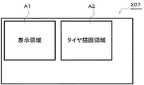
フレームバッファ207は、所定容量の2次元配列メモリからなり、たとえば、図6に示すように、表示領域A1、および、タイヤ描画領域A2等が設定されている。
表示領域A1は、上述の画像生成部204により生成される視界画像(ドライバーズ・ビュー)が書き込まれる領域である。
また、タイヤ描画領域A2は、上述のタイヤ描画部206により生成されるタイヤ画像が書き込まれる領域である。
なお、画像処理部108に備えられたフレームメモリが、このようなフレームバッファ207として機能しうる。
The
The display area A1 is an area in which a view field image (drivers view) generated by the
The tire drawing area A2 is an area where a tire image generated by the
Note that the frame memory provided in the image processing unit 108 can function as such a
表示制御部208は、フレームバッファ207の表示領域A1に格納された視界画像と、タイヤ描画領域A2に格納されたタイヤ画像とを適宜合成させた後、所定の画像信号に変換し、外部のモニタ等に表示させる。
たとえば、表示領域A1に図4に示すような視界画像が書き込まれ、また、タイヤ描画領域A2に図5(a)に示すようなタイヤ画像が書き込まれている場合、表示制御部208は、図7に示すように、視界画像の四隅にタイヤ画像を合成した表示画像を生成する。
そして、表示制御部208は、このように生成した表示画像を、所定の同期タイミングでビデオ信号に変換して、外部のモニタ等に供給する。
なお、画像処理部108がこのような表示制御部208として機能しうる。
The
For example, when the view field image as shown in FIG. 4 is written in the display area A1 and the tire image as shown in FIG. 5A is written in the tire drawing area A2, the
The
Note that the image processing unit 108 can function as such a
図8は、画像生成装置200において実行される荷重表示処理の流れを示すフローチャートである。以下、本図を参照して説明する。なお、この荷重表示処理は、たとえば、カーレースゲームの実行時において、ゲームの進行と共に開始される。
FIG. 8 is a flowchart showing the flow of the load display process executed in the
まず、カーレースゲームが開始されると(ステップS301)、画像生成装置200は、操作入力を受け付けて、レーシングカーの走行状況を更新する(ステップS302)。
つまり、操作入力受付部201が利用者によるアクセル操作、ブレーキ操作、ハンドル操作、および、シフトレバー操作等を受け付けると、走行状況管理部203は、操作に応じて走行状況(現在位置、走行方向、スピード等)を更新する。
First, when the car racing game is started (step S301), the
That is, when the operation
画像生成装置200は、フレームバッファ207に視界画像を描画する(ステップS303)。
つまり、画像生成部204は、画像情報記憶部202に記憶された画像情報、および、走行状況管理部203に管理されている走行状況に基づいて、視界画像(ドライバーズ・ビュー)を描画する。そして、描画した視界画像を、フレームバッファ207の表示領域A1に書き込む。
The
In other words, the
画像生成装置200は、走行状況に基づいて、荷重を算定する(ステップS304)。
つまり、荷重算定部205は、走行状況管理部203にて管理される走行状況に基づいて、利用者が操作するレーシングカーに加わる荷重(方向と大きさ)を算定する。
たとえば、荷重算定部205は、管理される走行状況が加減速の場合に、慣性力により生じた前後方向の荷重とその大きさを算定する。また、管理される走行状況が旋回の場合に、遠心力により生じた左右方向の荷重とその大きさを算定する。
The
That is, the
For example, the
画像生成装置200は、算定された荷重に基づいてタイヤ画像を描画する(ステップS305)。
つまり、タイヤ描画部206は、荷重算定部205が算定した荷重(向きと大きさ)に応じて、縦幅または横幅を変形させた平面のタイヤ画像を生成する。そして、生成したタイヤ画像を、フレームバッファ207のタイヤ描画領域A2に書き込む。
The
That is, the
画像生成装置200は、フレームバッファ207に基づいて画像を表示する(ステップS306)。
つまり、表示制御部208は、フレームバッファ207の表示領域A1に格納された視界画像と、タイヤ描画領域A2に格納されたタイヤ画像とを適宜合成させた後、所定の画像信号に変換し、外部のモニタ等に表示させる。
The
That is, the
たとえば、利用者の操作するレーシングカーが、コーナを左に旋回している際には、図9(a)に示すように、左の前後輪の横幅が狭まり、右の前後輪の横幅が伸びたタイヤ画像が、視界画像とともに表示される。これは、左旋回に伴い遠心力が生じ、この遠心力により右方向に向けて荷重が加えられた状態を示している。
つまり、利用者は、左のタイヤ幅が狭まり、右のタイヤ幅が伸びることにより、右方向の荷重(横G)を体感することができる。
逆に、レーシングカーが、コーナを右に旋回している際には、図9(b)に示すように、右の前後輪の横幅が狭まり、左の前後輪の横幅が伸びたタイヤ画像が、視界画像とともに表示されるが表示される。
つまり、利用者は、右タイヤの横幅が狭まり、左タイヤの横幅が伸びることにより、左方向の荷重(横G)を体感することができる。
For example, when the racing car operated by the user is turning left at the corner, as shown in FIG. 9A, the lateral width of the left front wheel is narrowed and the lateral width of the right front wheel is increased. The tire image is displayed together with the view image. This shows a state in which a centrifugal force is generated with the left turn, and a load is applied in the right direction by the centrifugal force.
That is, the user can experience a rightward load (lateral G) by narrowing the left tire width and extending the right tire width.
Conversely, when the racing car is turning to the right at the corner, as shown in FIG. 9B, the tire image in which the lateral width of the right front and rear wheels is narrowed and the lateral width of the left front and rear wheels is increased. Displayed together with the view image.
That is, the user can experience the load in the left direction (lateral G) by reducing the width of the right tire and increasing the width of the left tire.
また、レーシングカーが、コース上で急ブレーキをかけた際には、図9(c)に示すように、左右の前輪の縦幅が伸びたタイヤ画像が、視界画像とともに表示される。これは、ブレーキングによる減速に伴い慣性力が生じ、この慣性力により前方向に向けて荷重が加えられた状態を示している。
つまり、利用者は、前タイヤの縦幅が伸びることにより、前方向の荷重を体感することができる。
Further, when the racing car brakes suddenly on the course, as shown in FIG. 9C, a tire image in which the vertical width of the left and right front wheels is extended is displayed together with the view image. This shows a state in which an inertial force is generated along with deceleration by braking and a load is applied in the forward direction by the inertial force.
That is, the user can experience the load in the front direction by extending the vertical width of the front tire.
そして、画像生成装置200は、ゲームが完了したか否かを判別する(ステップS307)。
画像生成装置200は、ゲームが完了していないと判別した場合に、ステップS302に処理を戻し、上述のステップS302〜S307の処理を繰り返し実行する。
一方、ゲームが完了したと判別した場合に、画像生成装置200は、荷重表示処理を終える。
Then, the
When determining that the game is not completed, the
On the other hand, when it is determined that the game is completed, the
このように、本実施形態では、走行状況に応じた荷重を適切に視覚化することにより、仮想車両の挙動を容易に把握するができる。 Thus, in the present embodiment, the behavior of the virtual vehicle can be easily grasped by appropriately visualizing the load according to the traveling situation.
(他の実施形態)
上記実施形態では、タイヤ画像により、荷重を視覚化する場合について説明したが、さらに、視界画像をマスク画像で覆って合成し、視界画像の周辺部を半透明化等して、荷重を視覚化するようにしてもよい。
以下、視界画像の周辺部をマスク画像で多い、荷重を適切に視覚化するこの発明の他の実施の形態について、図面を参照して説明する。
(Other embodiments)
In the above embodiment, the case where the load is visualized by the tire image has been described. Further, the view image is covered with the mask image and synthesized, and the periphery of the view image is made translucent to visualize the load. You may make it do.
Hereinafter, another embodiment of the present invention in which the peripheral portion of the field-of-view image is often masked and the load is appropriately visualized will be described with reference to the drawings.
図10は、他の実施形態に係る画像生成装置の概要構成を示す模式図である。
画像生成装置400は、操作入力受付部201と、画像情報記憶部202と、走行状況管理部203と、画像生成部204と、荷重算定部205と、マスク描画部401と、タイヤ描画部206と、フレームバッファ207と、表示制御部208とを備える。
つまり、図2に示す画像生成装置200にマスク描画部401を付加したものである。
FIG. 10 is a schematic diagram illustrating a schematic configuration of an image generation apparatus according to another embodiment.
The
That is, the mask drawing unit 401 is added to the
マスク描画部401は、画像生成部204が生成する視界画像の周辺部を覆うために、額縁状のマスク画像を生成する。その際、荷重算定部205が算定した荷重(向きと大きさ)に基づいて、形状の異なるマスク画像を生成する。そして、生成したマスク画像をフレームバッファ207に書き込む。
The mask drawing unit 401 generates a frame-shaped mask image so as to cover the peripheral part of the view field image generated by the
たとえば、マスク描画部401は、図11(a)〜(e)に示すような大きさや配置位置が異なる四角形状のマスク画像を生成する。
まず、図11(a)のマスク画像は、荷重が後ろ方向に掛かっている場合(等速走行時や加速走行時)に生成される一例である。また、図11(b)のマスク画像は、荷重が前方向に掛かっている場合(ブレーキングによる減速時や急停止時)に生成される一例である。
図11(c)のマスク画像は、荷重が右方向に掛かっている場合(左旋回時)に生成される一例である。また、図11(d)のマスク画像は、荷重が左方向に掛かっている場合(右旋回時)に生成される一例である。
そして、図11(e)のマスク画像は、荷重が垂直方向(上下方向)に掛かっている場合(グラベルを走行時等)に生成される一例である。
For example, the mask drawing unit 401 generates rectangular mask images having different sizes and arrangement positions as shown in FIGS.
First, the mask image in FIG. 11A is an example generated when a load is applied in the backward direction (during constant speed travel or acceleration travel). Further, the mask image of FIG. 11B is an example generated when a load is applied in the forward direction (when decelerating or suddenly stopping by braking).
The mask image in FIG. 11C is an example generated when a load is applied in the right direction (when turning left). Further, the mask image in FIG. 11D is an example generated when a load is applied in the left direction (during a right turn).
The mask image in FIG. 11 (e) is an example generated when a load is applied in the vertical direction (up and down direction) (when traveling on the gravel).
つまり、マスク描画部401は、荷重が後方向に掛かっていれば、図11(a)に示すような四辺の幅を広げたマスク画像を生成し、逆に、荷重が前方向に掛かっていれば、図11(b)に示すような四辺の幅を狭めたマスク画像を生成する。
また、荷重が右方向に掛かっていれば、図11(c)に示すような左辺の幅を狭めるとともに、右辺の幅を広げたマスク画像を生成し、逆に、荷重が左方向に掛かっていれば、図11(d)に示すような左辺の幅を広げるとともに、右辺の幅を狭めたマスク画像を生成する。
なお、画像処理部108が、このようなマスク描画部401として機能しうる。
In other words, if the load is applied in the backward direction, the mask drawing unit 401 generates a mask image with the four sides widened as shown in FIG. 11A, and conversely, the load is applied in the forward direction. For example, a mask image in which the widths of the four sides are narrowed as shown in FIG.
If the load is applied in the right direction, a mask image is generated in which the width of the left side is reduced and the width of the right side is increased as shown in FIG. 11C. Conversely, the load is applied in the left direction. Then, a mask image in which the width of the left side is widened and the width of the right side is narrowed as shown in FIG.
Note that the image processing unit 108 can function as such a mask drawing unit 401.
そして、表示制御部208は、マスク描画部401により生成されたこのようなマスク画像と、画像生成部204により生成された視界画像とを合成させ、視界画像の周辺部を半透明化する。なお、周辺部を半透明化する以外にも、同色で塗りつぶしたり、ぼやけさせてもよい。
さらに、表示制御部208は、周辺部を半透明化等した視界画像に、タイヤ描画部206により生成されたタイヤ画像を合成する。
これにより、図12に例示するような画像が外部のモニタ等に表示される。
Then, the
Further, the
Thereby, an image as illustrated in FIG. 12 is displayed on an external monitor or the like.
まず、図12(a)は、利用者の操作するレーシングカーが、コーナを左に旋回している場合に表示される画像である。つまり、左の前後輪の横幅が狭まり、右の前後輪の横幅が伸びたタイヤ画像が表示され、さらに、表示位置が左に移動した視界画像が表示される。これは、左旋回に伴い遠心力が生じ、この遠心力により右方向に向けて荷重が加えられた状態を示している。
このように、表示位置が左に移動することにより、利用者は、相対的に右方向の荷重(横G)が自分に掛かり、首が右に持っていかれていると体感することができる。
First, FIG. 12A is an image displayed when the racing car operated by the user is turning the corner to the left. That is, a tire image in which the width of the left front and rear wheels is narrowed and the width of the right front and rear wheels is increased is displayed, and a view image in which the display position is moved to the left is displayed. This shows a state in which a centrifugal force is generated with the left turn, and a load is applied in the right direction by the centrifugal force.
Thus, by moving the display position to the left, the user can feel that a relatively rightward load (lateral G) is applied to the user and the neck is held to the right.
また、図12(b)は、レーシングカーが、コーナを右に旋回している場合に表示される画像である。つまり、右の前後輪の横幅が狭まり、左の前後輪の横幅が伸びたタイヤ画像が表示され、さらに、表示位置が右に移動した視界画像が表示される。これは、右旋回に伴い遠心力が生じ、この遠心力により左方向に向けて荷重が加えられた状態を示している。
このように、表示位置が右に移動することにより、利用者は、相対的に左方向の荷重が自分に掛かり、首が左に持っていかれていると体感することができる。
FIG. 12B is an image displayed when the racing car is turning the corner to the right. That is, a tire image in which the lateral width of the right front and rear wheels is narrowed and the lateral width of the left front and rear wheels is expanded is displayed, and a field-of-view image in which the display position is moved to the right is displayed. This shows a state in which a centrifugal force is generated with a right turn and a load is applied in the left direction by the centrifugal force.
Thus, by moving the display position to the right, the user can feel that a relatively leftward load is applied to him and the neck is held to the left.
そして、図12(c)は、レーシングカーが、コース上で急ブレーキをかけた場合に表示される画像である。つまり、左右の前輪の縦幅が伸びたタイヤ画像が表示され、さらに、表示範囲が拡大した視界画像が表示される。これは、ブレーキングによる減速に伴い慣性力が生じ、この慣性力により前方向に向けて荷重が加えられた状態を示している。
このように、表示範囲が拡大することにより、利用者は、相対的に前方向の荷重が自分に掛かり、首が前に持っていかれていると体感することができる。
FIG. 12C shows an image displayed when the racing car suddenly brakes on the course. That is, a tire image in which the vertical width of the left and right front wheels is extended is displayed, and a view field image in which the display range is expanded is displayed. This shows a state in which an inertial force is generated along with deceleration by braking and a load is applied in the forward direction by the inertial force.
In this way, by expanding the display range, the user can feel that a relatively forward load is applied to the user and the neck is held forward.
このように、他の実施の形態でも、走行状況に応じた荷重を適切に視覚化することにより、仮想車両の挙動を容易に把握するができる。 Thus, also in other embodiments, the behavior of the virtual vehicle can be easily grasped by appropriately visualizing the load according to the traveling situation.
上記の実施形態では、視界画像の四隅にタイヤ画像を合成して表示する場合について説明したが、タイヤ画像を合成する位置は、視界画像の四隅に限られず任意である。
また、上記の実施形態では、算定された荷重に応じて、タイヤ画像の形状を変形させる場合について説明したが、他に、色等を荷重に応じて変化させるようにしてもよい。
たとえば、タイヤがグリップできる荷重に近づくに連れて、赤色に変化させるようにし、スピン等が生じる限界荷重を利用者に報知できるようにしてもよい。
In the above-described embodiment, the case where the tire images are combined and displayed at the four corners of the view image has been described. However, the positions where the tire images are combined are not limited to the four corners of the view image and are arbitrary.
In the above-described embodiment, the case where the shape of the tire image is deformed according to the calculated load has been described. Alternatively, the color or the like may be changed according to the load.
For example, as the tire approaches a load that can be gripped, it may be changed to red so that the user can be notified of the limit load that causes spin or the like.
また、上記実施形態では、仮想車両としてレーシングカーを一例にして説明したが、他のタイヤを有する車両であれば適宜適用可能である。
たとえば、仮想空間内を走行する2輪のオートバイの場合、表示するタイヤ画像を2つにし、さらに、補助線としての中心線も同時に表示する。そして、旋回時には、中心線から前後輪を左右何れかにずらして横幅を伸ばしたタイヤ画像を生成して表示することにより、左右何れかの荷重を表す。
このように、2輪のオートバイ等に適用した場合でも、走行状況に応じた荷重を適切に視覚化することにより、仮想車両の挙動を容易に把握するができる。
In the above-described embodiment, the racing car is described as an example of the virtual vehicle. However, any vehicle having other tires can be appropriately applied.
For example, in the case of a two-wheel motorcycle traveling in a virtual space, two tire images are displayed, and a center line as an auxiliary line is also displayed at the same time. When turning, a tire image with the lateral width extended by shifting the front and rear wheels from the center line to the left or right is generated and displayed to represent the left or right load.
Thus, even when applied to a two-wheeled motorcycle or the like, the behavior of the virtual vehicle can be easily grasped by appropriately visualizing the load corresponding to the traveling state.
以上説明したように、本発明によれば、走行状況に応じた荷重を適切に視覚化することにより、仮想車両の挙動を容易に把握することができる。 As described above, according to the present invention, it is possible to easily grasp the behavior of the virtual vehicle by appropriately visualizing the load according to the traveling state.
100 ゲーム装置
101 CPU
102 ROM
103 RAM
104 インターフェース
105 コントローラ
106 外部メモリ
107 DVD−ROMドライブ
108 画像処理部
109 音声処理部
110 NIC
200 画像生成装置
201 操作入力受付部
202 画像情報記憶部
203 走行状況管理部
204 画像生成部
205 荷重算定部
206 タイヤ描画部
207 フレームバッファ
208 表示制御部
100 game machine 101 CPU
102 ROM
103 RAM
104 Interface 105 Controller 106 External Memory 107 DVD-ROM Drive 108 Image Processing Unit 109
DESCRIPTION OF
Claims (9)
当該走行路上を走行させる仮想車両に向けた操作入力を受け付ける操作入力受付部と、
受け付けられた当該操作入力に応じて走行する当該仮想車両の前方画像を生成する前方画像生成部と、
当該仮想車両の走行状況に基づく荷重に応じて、当該仮想車両における当該走行路との接地面を模した形状の異なるタイヤ画像を生成するタイヤ画像生成部と、
生成された当該前方画像と当該タイヤ画像とを合成して表示する表示制御部と、を備える、
ことを特徴とする画像生成装置。 An image information storage unit that stores image information that defines a landscape image including a travel path arranged in a virtual space;
An operation input receiving unit that receives an operation input for a virtual vehicle that travels on the travel path ;
A front image generation unit that generates a front image of the virtual vehicle that travels according to the received operation input;
A tire image generating unit that generates tire images having different shapes simulating a contact surface with the traveling road in the virtual vehicle according to a load based on a traveling state of the virtual vehicle ;
A display control unit that combines and displays the generated front image and the tire image;
An image generation apparatus characterized by that.
前記タイヤ画像生成部は、当該荷重に応じて、縦幅または横幅がそれぞれ異なる前後輪4つのタイヤ画像を生成し、
前記表示制御部は、当該4つのタイヤ画像を当該前方画像の四隅に合成して表示する、
ことを特徴とするもの。 The image generation apparatus according to claim 1,
The tire image generation unit, in accordance with the load, the vertical width or horizontal width produce different front and rear wheels four tires images respectively,
The display control unit synthesizes and displays the four tire images at the four corners of the front image.
It is characterized by that.
当該走行路上を走行させる仮想車両に向けた操作入力を受け付ける操作入力受付部と、
受け付けられた当該操作入力に基づいて、当該仮想車両の走行状況を管理する走行状況管理部と、
記憶された当該画像情報および管理されている当該走行状況に基づいて、当該仮想車両の前方画像を生成する前方画像生成部と、
管理される当該走行状況に基づいて、当該仮想車両に加わる荷重を算定する荷重算定部と、
算定された当該荷重に応じて、当該仮想車両における当該走行路との接地面を模した形状の異なるタイヤ画像を生成するタイヤ画像生成部と、
生成された当該前方画像と当該タイヤ画像とを合成して表示する表示制御部と、を備える、
ことを特徴とする画像生成装置。 An image information storage unit that stores image information that defines a landscape image including a travel path arranged in a virtual space;
An operation input receiving unit that receives an operation input for a virtual vehicle that travels on the travel path ;
Based on the received operation input, a traveling state management unit that manages the traveling state of the virtual vehicle;
A front image generation unit that generates a front image of the virtual vehicle based on the stored image information and the managed traveling state;
A load calculation unit for calculating a load applied to the virtual vehicle based on the managed traveling state;
In accordance with the calculated load, a tire image generation unit that generates a tire image having a different shape imitating a contact surface with the travel path in the virtual vehicle ;
A display control unit that combines and displays the generated front image and the tire image;
An image generation apparatus characterized by that.
前記荷重算定部は、当該走行状況が加減速の場合に、慣性力により生じた当該仮想車両に加わる荷重を算定し、当該走行状況が旋回の場合に、遠心力により生じた当該仮想車両に加わる荷重を算定し、
前記タイヤ画像生成部は、算定された当該荷重に応じて、縦幅または横幅がそれぞれ異なる前後輪4つのタイヤ画像を生成し、
前記表示制御部は、当該4つのタイヤ画像を当該前方画像の四隅に合成して表示する、
ことを特徴とするもの。 The image generation device according to claim 3,
The load calculating unit calculates a load applied to the virtual vehicle caused by an inertial force when the traveling state is acceleration / deceleration, and applies to the virtual vehicle generated by a centrifugal force when the traveling state is turning. Calculate the load
The tire image generation unit, depending on the calculated the load, the vertical width or horizontal width produce different front and rear wheels four tires images respectively,
The display control unit synthesizes and displays the four tire images at the four corners of the front image.
It is characterized by that.
生成された当該前方画像の周辺部を覆うための異なるマスク画像を、当該仮想車両の走行状況に基づく荷重に応じて生成するマスク画像生成部を、さらに備え、
前記表示制御部は、生成された当該前方画像と当該マスク画像とを合成した後に、さらに当該タイヤ画像を合成する、
ことを特徴とするもの。 The image generation apparatus according to any one of claims 1 to 4, wherein:
A mask image generation unit that generates a different mask image for covering the periphery of the generated front image according to a load based on the traveling state of the virtual vehicle ;
The display control unit further synthesizes the tire image after synthesizing the generated front image and the mask image.
It is characterized by that.
前記操作入力受付部が行う、当該走行路上を走行させる仮想車両に向けた操作入力を受け付ける操作入力受付工程と、
前記画像生成部が行う、受け付けられた当該操作入力に応じて走行する当該仮想車両の前方画像を、記憶された当該画像情報に基づいて生成する前方画像生成工程と、
前記タイヤ描画部が行う、当該仮想車両の走行状況に基づく荷重に応じて、当該仮想車両における当該走行路との接地面を模した形状の異なるタイヤ画像を生成するタイヤ画像生成工程と、
前記表示制御部が行う、生成された当該前方画像と当該タイヤ画像とを所定の表示装置に合成して表示する表示制御工程と、を備える、
ことを特徴とする荷重表示方法。 An image information storage unit, an operation input reception unit, an image generator, a load display method using a tire drawing unit, and a display control unit running, the image information storage unit, arranged in the virtual space Stores image information that defines landscape images including roads ,
An operation input receiving step for receiving an operation input for a virtual vehicle that travels on the travel road , performed by the operation input receiving unit ;
A forward image generation step of generating, based on the stored image information, a forward image of the virtual vehicle that travels according to the received operation input, performed by the image generation unit ;
A tire image generating step for generating a tire image having a different shape imitating a contact surface with the traveling road in the virtual vehicle according to a load based on a traveling state of the virtual vehicle performed by the tire drawing unit ;
A display control step for combining the generated front image and the tire image on a predetermined display device and displaying the generated image by the display control unit ,
A load display method characterized by that.
前記操作入力受付部が行う、当該走行路上を走行させる仮想車両に向けた操作入力を受け付ける操作入力受付工程と、
前記走行状況管理部が行う、受け付けられた当該操作入力に基づいて、当該仮想車両の走行状況を管理する走行状況管理工程と、
前記画像生成部が行う、記憶された当該画像情報および管理されている当該走行状況に基づいて、当該仮想車両の前方画像を生成する前方画像生成工程と、
前記荷重算定部が行う、管理される当該走行状況に基づいて、当該仮想車両に加わる荷重を算定する荷重算定工程と、
前記タイヤ描画部が行う、算定された当該荷重に応じて、当該仮想車両における当該走行路との接地面を模した形状の異なるタイヤ画像を生成するタイヤ画像生成工程と、
前記表示制御部が行う、生成された当該前方画像と当該タイヤ画像とを合成して表示する表示制御工程と、を備える、
ことを特徴とする荷重表示方法。 A load display method using an image information storage unit , an operation input reception unit, a traveling state management unit, an image generation unit, a load calculation unit, a tire drawing unit, and a display control unit , wherein the image information storage unit The unit stores image information that defines a landscape image including a traveling path arranged in the virtual space,
An operation input receiving step for receiving an operation input for a virtual vehicle that travels on the travel road , performed by the operation input receiving unit ;
Based on the accepted operation input performed by the traveling state management unit, a traveling state management step for managing the traveling state of the virtual vehicle;
A forward image generation step for generating a forward image of the virtual vehicle based on the stored image information and the managed running state, which is performed by the image generation unit ;
A load calculating step for calculating a load applied to the virtual vehicle based on the traveling state managed by the load calculating unit ;
According to the calculated load performed by the tire drawing unit, a tire image generation step for generating a tire image having a different shape imitating a contact surface with the traveling road in the virtual vehicle ,
A display control step for combining and displaying the generated front image and the tire image, which is performed by the display control unit ,
A load display method characterized by that.
仮想空間内に配置される走行路を含んだ風景画像を規定する画像情報を記憶する画像情報記憶部
当該走行路上を走行させる仮想車両に向けた操作入力を受け付ける操作入力受付部、
受け付けられた当該操作入力に応じて走行する当該仮想車両の前方画像を生成する前方画像生成部、
当該仮想車両の走行状況に基づく荷重に応じて、当該仮想車両における当該走行路との接地面を模した形状の異なるタイヤ画像を生成するタイヤ画像生成部、
生成された当該前方画像と当該タイヤ画像とを合成して表示する表示制御部、
として機能させることを特徴とするプログラム。 Computer
An image information storage unit that stores image information that defines a landscape image including a traveling path arranged in a virtual space
An operation input receiving unit that receives an operation input for a virtual vehicle that travels on the travel path ;
A front image generation unit that generates a front image of the virtual vehicle that travels according to the received operation input;
A tire image generation unit that generates a tire image having a different shape imitating a contact surface with the travel path in the virtual vehicle according to a load based on the travel state of the virtual vehicle ,
A display control unit that synthesizes and displays the generated front image and the tire image;
A program characterized by functioning as
仮想空間内に配置される走行路を含んだ風景画像を規定する画像情報を記憶する画像情報記憶部、
当該走行路上を走行させる仮想車両に向けた操作入力を受け付ける操作入力受付部、
受け付けられた当該操作入力に基づいて、当該仮想車両の走行状況を管理する走行状況管理部、
記憶された当該画像情報および管理されている当該走行状況に基づいて、当該仮想車両の前方画像を生成する前方画像生成部、
管理される当該走行状況に基づいて、当該仮想車両に加わる荷重を算定する荷重算定部、
算定された当該荷重に応じて、当該仮想車両における当該走行路との接地面を模した形状の異なるタイヤ画像を生成するタイヤ画像生成部、
生成された当該前方画像と当該タイヤ画像とを合成して表示する表示制御部、
として機能させることを特徴とするプログラム。 Computer
An image information storage unit for storing image information defining a landscape image including a travel path arranged in a virtual space;
An operation input receiving unit that receives an operation input for a virtual vehicle that travels on the travel path ;
Based on the received operation input, a traveling state management unit that manages the traveling state of the virtual vehicle,
A front image generation unit that generates a front image of the virtual vehicle based on the stored image information and the managed traveling state;
A load calculation unit for calculating a load applied to the virtual vehicle based on the managed traveling state;
According to the calculated load, a tire image generation unit that generates a tire image having a different shape imitating a contact surface with the traveling road in the virtual vehicle ,
A display control unit that synthesizes and displays the generated front image and the tire image;
A program characterized by functioning as
Priority Applications (7)
| Application Number | Priority Date | Filing Date | Title |
|---|---|---|---|
| JP2004257260A JP3766425B2 (en) | 2004-09-03 | 2004-09-03 | Image generating apparatus, load display method, and program |
| US11/574,574 US7843453B2 (en) | 2004-09-03 | 2005-09-01 | Video generation device, load display method, recording medium, and program |
| KR1020077004829A KR100906068B1 (en) | 2004-09-03 | 2005-09-01 | Video generation device, load display method and medium for recording the program |
| EP05781341A EP1787696A4 (en) | 2004-09-03 | 2005-09-01 | Video generation device, load display method, recording medium, and program |
| CN2005800297144A CN101022861B (en) | 2004-09-03 | 2005-09-01 | Video generation device, load display method |
| PCT/JP2005/016023 WO2006025495A1 (en) | 2004-09-03 | 2005-09-01 | Video generation device, load display method, recording medium, and program |
| TW094130081A TWI291888B (en) | 2004-09-03 | 2005-09-02 | Image generating apparatus, load display method and recording medium |
Applications Claiming Priority (1)
| Application Number | Priority Date | Filing Date | Title |
|---|---|---|---|
| JP2004257260A JP3766425B2 (en) | 2004-09-03 | 2004-09-03 | Image generating apparatus, load display method, and program |
Publications (2)
| Publication Number | Publication Date |
|---|---|
| JP2006068375A JP2006068375A (en) | 2006-03-16 |
| JP3766425B2 true JP3766425B2 (en) | 2006-04-12 |
Family
ID=36000144
Family Applications (1)
| Application Number | Title | Priority Date | Filing Date |
|---|---|---|---|
| JP2004257260A Expired - Fee Related JP3766425B2 (en) | 2004-09-03 | 2004-09-03 | Image generating apparatus, load display method, and program |
Country Status (7)
| Country | Link |
|---|---|
| US (1) | US7843453B2 (en) |
| EP (1) | EP1787696A4 (en) |
| JP (1) | JP3766425B2 (en) |
| KR (1) | KR100906068B1 (en) |
| CN (1) | CN101022861B (en) |
| TW (1) | TWI291888B (en) |
| WO (1) | WO2006025495A1 (en) |
Families Citing this family (4)
| Publication number | Priority date | Publication date | Assignee | Title |
|---|---|---|---|---|
| JP3765422B2 (en) * | 2004-04-28 | 2006-04-12 | コナミ株式会社 | Image generating apparatus, acceleration display method, and program |
| CN104517491B (en) * | 2014-12-16 | 2018-12-04 | 北京中交兴路车联网科技有限公司 | A kind of vehicle driving simulation system and method |
| CN109717842A (en) * | 2017-10-31 | 2019-05-07 | 北京帕斯泰克科技有限公司 | A kind of video aiding sensors positioning device and method for pulse-taking instrument equipment |
| JP7270008B2 (en) * | 2020-09-08 | 2023-05-09 | カムツス コーポレーション | Game providing method, computer program, computer-readable recording medium, and computer device |
Family Cites Families (14)
| Publication number | Priority date | Publication date | Assignee | Title |
|---|---|---|---|---|
| JP3254091B2 (en) * | 1994-11-09 | 2002-02-04 | 株式会社ナムコ | Three-dimensional simulator device and image synthesizing method |
| US5755620A (en) * | 1995-04-03 | 1998-05-26 | Kabushiki Kaisha Sega Enterprises | Game system and data processing method thereof |
| JPH08276074A (en) * | 1995-04-03 | 1996-10-22 | Sega Enterp Ltd | Game machine and its data processing method |
| DE19541430C2 (en) * | 1995-11-07 | 2001-04-26 | Autoliv Dev | Electrically controlled seat belt retractor |
| JP3273729B2 (en) * | 1996-06-07 | 2002-04-15 | コナミ株式会社 | Driving game machine |
| US6142871A (en) * | 1996-07-31 | 2000-11-07 | Konami Co., Ltd. | Apparatus, method and recorded programmed medium for simulating driving using mirrors displayed in a game space |
| JPH11114222A (en) | 1997-10-09 | 1999-04-27 | Konami Co Ltd | Competitive game apparatus, character display method therein and computer-aided readable recording medium having character display program recorded therein |
| JPH11146978A (en) * | 1997-11-17 | 1999-06-02 | Namco Ltd | Three-dimensional game unit, and information recording medium |
| DE60205187T2 (en) * | 2001-09-18 | 2006-06-14 | Sumitomo Rubber Ind | Method for simulating a rolling tire |
| JP3843246B2 (en) * | 2002-07-02 | 2006-11-08 | 株式会社バンダイナムコゲームス | PROGRAM, INFORMATION STORAGE MEDIUM, AND GAME DEVICE |
| JP3556660B1 (en) * | 2003-03-31 | 2004-08-18 | コナミ株式会社 | Image generating apparatus, load display method, and program |
| US7145442B1 (en) * | 2003-10-14 | 2006-12-05 | Yu Hei Sunny Wai | Vehicle operation display system |
| US8133115B2 (en) * | 2003-10-22 | 2012-03-13 | Sony Computer Entertainment America Llc | System and method for recording and displaying a graphical path in a video game |
| JP2006010325A (en) * | 2004-06-22 | 2006-01-12 | Sharp Corp | Display device, instrument panel, motor vehicle, and game system |
-
2004
- 2004-09-03 JP JP2004257260A patent/JP3766425B2/en not_active Expired - Fee Related
-
2005
- 2005-09-01 EP EP05781341A patent/EP1787696A4/en not_active Withdrawn
- 2005-09-01 KR KR1020077004829A patent/KR100906068B1/en active IP Right Grant
- 2005-09-01 US US11/574,574 patent/US7843453B2/en not_active Expired - Fee Related
- 2005-09-01 CN CN2005800297144A patent/CN101022861B/en not_active Expired - Fee Related
- 2005-09-01 WO PCT/JP2005/016023 patent/WO2006025495A1/en active Application Filing
- 2005-09-02 TW TW094130081A patent/TWI291888B/en active
Also Published As
| Publication number | Publication date |
|---|---|
| WO2006025495A1 (en) | 2006-03-09 |
| KR100906068B1 (en) | 2009-07-03 |
| US7843453B2 (en) | 2010-11-30 |
| TWI291888B (en) | 2008-01-01 |
| TW200613040A (en) | 2006-05-01 |
| JP2006068375A (en) | 2006-03-16 |
| CN101022861B (en) | 2010-08-04 |
| KR20070044474A (en) | 2007-04-27 |
| EP1787696A4 (en) | 2007-12-12 |
| CN101022861A (en) | 2007-08-22 |
| US20080094390A1 (en) | 2008-04-24 |
| EP1787696A1 (en) | 2007-05-23 |
Similar Documents
| Publication | Publication Date | Title |
|---|---|---|
| KR100871274B1 (en) | Image producing device, acceleration displaying method, and computer-readable information recording medium having a program recorded thereon | |
| KR100906069B1 (en) | Image creating device, load display method, and medium for recording the program | |
| JP3827692B2 (en) | Operation input device, operation evaluation method, and program | |
| KR100921882B1 (en) | Image creating device, load display method, and medium for recording the program | |
| KR100906068B1 (en) | Video generation device, load display method and medium for recording the program | |
| JP3887810B2 (en) | Game device | |
| KR100823782B1 (en) | Image producing device, speed expressing method, and computer-readable information recording medium having a program recorded thereon | |
| JP3556660B1 (en) | Image generating apparatus, load display method, and program | |
| JP2004325828A (en) | Simulator, program, and information storage medium | |
| JP3783735B2 (en) | Image processing apparatus and game apparatus having the same | |
| JP3866743B2 (en) | Game device, odds presentation method, and program | |
| JP2007304727A (en) | Program, information storage medium, and image generation device | |
| JP2010284258A (en) | Game device and game program |
Legal Events
| Date | Code | Title | Description |
|---|---|---|---|
| A521 | Request for written amendment filed |
Free format text: JAPANESE INTERMEDIATE CODE: A523 Effective date: 20051228 |
|
| TRDD | Decision of grant or rejection written | ||
| A01 | Written decision to grant a patent or to grant a registration (utility model) |
Free format text: JAPANESE INTERMEDIATE CODE: A01 Effective date: 20060124 |
|
| A61 | First payment of annual fees (during grant procedure) |
Free format text: JAPANESE INTERMEDIATE CODE: A61 Effective date: 20060126 |
|
| R150 | Certificate of patent or registration of utility model |
Free format text: JAPANESE INTERMEDIATE CODE: R150 Ref document number: 3766425 Country of ref document: JP Free format text: JAPANESE INTERMEDIATE CODE: R150 |
|
| A711 | Notification of change in applicant |
Free format text: JAPANESE INTERMEDIATE CODE: A712 Effective date: 20060427 |
|
| RD03 | Notification of appointment of power of attorney |
Free format text: JAPANESE INTERMEDIATE CODE: A7423 Effective date: 20060525 |
|
| S111 | Request for change of ownership or part of ownership |
Free format text: JAPANESE INTERMEDIATE CODE: R313111 |
|
| R350 | Written notification of registration of transfer |
Free format text: JAPANESE INTERMEDIATE CODE: R350 |
|
| A072 | Dismissal of procedure [no reply to invitation to correct request for examination] |
Free format text: JAPANESE INTERMEDIATE CODE: A072 Effective date: 20060913 |
|
| FPAY | Renewal fee payment (event date is renewal date of database) |
Free format text: PAYMENT UNTIL: 20090203 Year of fee payment: 3 |
|
| S531 | Written request for registration of change of domicile |
Free format text: JAPANESE INTERMEDIATE CODE: R313531 |
|
| FPAY | Renewal fee payment (event date is renewal date of database) |
Free format text: PAYMENT UNTIL: 20090203 Year of fee payment: 3 |
|
| R350 | Written notification of registration of transfer |
Free format text: JAPANESE INTERMEDIATE CODE: R350 |
|
| FPAY | Renewal fee payment (event date is renewal date of database) |
Free format text: PAYMENT UNTIL: 20090203 Year of fee payment: 3 |
|
| FPAY | Renewal fee payment (event date is renewal date of database) |
Free format text: PAYMENT UNTIL: 20100203 Year of fee payment: 4 |
|
| R250 | Receipt of annual fees |
Free format text: JAPANESE INTERMEDIATE CODE: R250 |
|
| FPAY | Renewal fee payment (event date is renewal date of database) |
Free format text: PAYMENT UNTIL: 20110203 Year of fee payment: 5 |
|
| R250 | Receipt of annual fees |
Free format text: JAPANESE INTERMEDIATE CODE: R250 |
|
| FPAY | Renewal fee payment (event date is renewal date of database) |
Free format text: PAYMENT UNTIL: 20110203 Year of fee payment: 5 |
|
| FPAY | Renewal fee payment (event date is renewal date of database) |
Free format text: PAYMENT UNTIL: 20120203 Year of fee payment: 6 |
|
| R250 | Receipt of annual fees |
Free format text: JAPANESE INTERMEDIATE CODE: R250 |
|
| FPAY | Renewal fee payment (event date is renewal date of database) |
Free format text: PAYMENT UNTIL: 20130203 Year of fee payment: 7 |
|
| R250 | Receipt of annual fees |
Free format text: JAPANESE INTERMEDIATE CODE: R250 |
|
| FPAY | Renewal fee payment (event date is renewal date of database) |
Free format text: PAYMENT UNTIL: 20140203 Year of fee payment: 8 |
|
| R250 | Receipt of annual fees |
Free format text: JAPANESE INTERMEDIATE CODE: R250 |
|
| R250 | Receipt of annual fees |
Free format text: JAPANESE INTERMEDIATE CODE: R250 |
|
| R250 | Receipt of annual fees |
Free format text: JAPANESE INTERMEDIATE CODE: R250 |
|
| S802 | Written request for registration of partial abandonment of right |
Free format text: JAPANESE INTERMEDIATE CODE: R311802 |
|
| R250 | Receipt of annual fees |
Free format text: JAPANESE INTERMEDIATE CODE: R250 |
|
| R350 | Written notification of registration of transfer |
Free format text: JAPANESE INTERMEDIATE CODE: R350 |
|
| R250 | Receipt of annual fees |
Free format text: JAPANESE INTERMEDIATE CODE: R250 |
|
| R250 | Receipt of annual fees |
Free format text: JAPANESE INTERMEDIATE CODE: R250 |
|
| R250 | Receipt of annual fees |
Free format text: JAPANESE INTERMEDIATE CODE: R250 |
|
| R250 | Receipt of annual fees |
Free format text: JAPANESE INTERMEDIATE CODE: R250 |
|
| R250 | Receipt of annual fees |
Free format text: JAPANESE INTERMEDIATE CODE: R250 |
|
| R250 | Receipt of annual fees |
Free format text: JAPANESE INTERMEDIATE CODE: R250 |
|
| LAPS | Cancellation because of no payment of annual fees |