JP3762529B2 - Sealing device - Google Patents
Sealing device Download PDFInfo
- Publication number
- JP3762529B2 JP3762529B2 JP26934497A JP26934497A JP3762529B2 JP 3762529 B2 JP3762529 B2 JP 3762529B2 JP 26934497 A JP26934497 A JP 26934497A JP 26934497 A JP26934497 A JP 26934497A JP 3762529 B2 JP3762529 B2 JP 3762529B2
- Authority
- JP
- Japan
- Prior art keywords
- housing
- lip
- outer peripheral
- shaped protrusion
- atmosphere side
- Prior art date
- Legal status (The legal status is an assumption and is not a legal conclusion. Google has not performed a legal analysis and makes no representation as to the accuracy of the status listed.)
- Expired - Lifetime
Links
Images
Description
【0001】
【発明の属する技術分野】
本発明は、たとえば自動車のパワーステアリング等の高圧が作用する軸封部に用いられる密封装置に関し、特に外周固定部のシール構造に関する。
【0002】
【従来の技術】
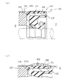
従来のこの種の高圧用の密封装置としては、たとえば図3に示すようなものが知られている。
【0003】
すなわち、密封装置100の外周は、ハウジング101の軸孔101a内周に対して適正な外周しめしろによって嵌合固定される外周固定部102となっている。この外周固定部102は、金属環105外周に被覆された外周ゴム部106によってシール性が高められていた。
【0004】
また、このような耐圧シールの場合には、密封対象流体の圧力によって密封装置100が大気側に抜けないように、外周固定部102の大気側端面が抜け止め用の押え部材103によって押さえられた状態で使用される。
【0005】
押え部材103には、実機組立時において取扱い易いように、押え部材103の外径端部には面取り部104が設けられ、押え部材103をハウジング101の軸孔101a内に差し込み易くしていた。
【0006】
【発明が解決しようとする課題】
しかし上記した従来の密封装置の場合には、ハウジング101に嵌合されることによって、図3(b)に示すように、外周固定部102の外周ゴム部106が、金属環105とハウジング101との間で径方向に圧縮され、圧縮された外周ゴム部106が軸方向密封対象流体側Oおよび大気側Aへはみ出すために、外周固定部106に強い面圧(張り力)を保つことができない。
【0007】
外周固定部102の大気側端面には押え部材103が突当てられているものの、その外径端部には面取り部104が設けられているので、外周ゴム部106の軸方向大気側Aへのはみ出しを規制することができない。
【0008】
この状態で常に高温高圧条件で使用されると、外周固定部106にへたりが生じ、使用圧P0に対して外周面圧paが小さくなり、外周から油漏れが生じるおそれがある。
【0009】
本発明は上記した従来技術の問題を解決するためになされたもので、その目的とするところは、ハウジングに固定される外周固定部のシール性向上を図り、ひいては寿命向上を図り得る密封装置を提供することにある。
【0010】
【課題を解決するための手段】
上記目的を達成するために、本発明にあっては、ハウジングの軸孔内周と移動軸間の隙間をシールするもので、環状の装置本体外周におけるハウジングの軸孔内周に、円筒部と該円筒部の大気側端部に設けられる内向きフランジ部とを備える断面L字形状の金属環の前記円筒部の外周に被覆される外周ゴム部で接触面圧を発生させて嵌合固定される外周固定部を有する密封装置において、前記外周固定部の大気側端部における断面L字形状の金属環の前記円筒部と前記内向きフランジ部とが接続された角部に、当該大気側端部よりも大気側に突出し、かつ、前記外周ゴム部から連続して、前記ハウジングの軸孔内周に密接するゴム状弾性材製のリップ状突起を設け、前記外周固定部の大気側端部は前記金属環の内向きフランジ部が露出しており、当該内向きフランジ部がハウジングの軸孔に差し込まれる押え部材端面にほぼ全幅にわたって当接し、押え部材端面の外径端部には面取りが施され、該面取り部とハウジング内周間の隙間に前記リップ状突起が当該隙間を埋めてハウジング内周面に接触面圧を発生可能なボリュームで充填され、前記リップ状突起が前記面取り部によって半径方向外方に向けて押し広げられ、前記リップ状突起の外周がハウジング内周面に強く圧接され、接触面圧が高められる構成としたことを特徴とする。
【0011】
リップ状突起によってハウジングとの間で局部的に高い面圧が発生し、外周シール性が向上する。外周固定部全体の接触面圧が低下しても、リップ状突起によって外周固定部とハウジング間の隙間がシールされる。
【0012】
リップ状突起を外周固定部の大気側端部に設けたことを特徴とする。
【0013】
このようにすれば、密封装置の外周嵌合部からのシール漏れが大気側端部において防止される。
【0014】
外周固定部の大気側端部はハウジングの軸孔に差し込まれる押え部材端面に当接し、押え部材端面の外径端部には面取りが施され、該面取り部とハウジング内周間の隙間にリップ状突起が充填される構成としたことを特徴とする。
【0015】
このようにすれば、実機組立時に、押え部材を外周固定部の大気側端面に突き当てると、押え部材の面取り部とハウジング内周面との間に形成される環状の隙間内にリップ状突起が入り込み、リップ状突起が面取り部によって半径方向外方に向けて押し広げられ、リップ状突起の外周がハウジング内周面に強く圧接され接触面圧が高められる。
【0016】
この接触面圧は、密封対象流体が高圧の場合には、圧力によって密封装置が軸方向押えに対して軸方向に押し付けられるので、接触面圧がさらに大きくなる。
【0019】
【発明の実施の形態】
以下に本発明を図示の実施の形態に基づいて説明する。
【0020】
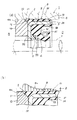
図1は本発明の第1の実施の形態に係る密封装置を示している。
【0021】
本実施の形態に係る密封装置1は、外周固定部の大気側端部にリップ状突起2を設けたものである。
【0022】
すなわち、図において、1は密封装置全体を示している。この密封装置1は、断面L字形状の金属環3と、金属環3に一体的に焼き付けられるシールリップ4を備えたゴム状弾性体5と、シールリップ4を支える樹脂製のバックアップリング6と、から構成されている。
【0023】
金属環3は断面L字形状で、円筒部31と、円筒部31の大気側端部に設けられる内向きフランジ部32と、を備えている。内向きフランジ部32の内径は、移動軸7の外周との間の所定の環状隙間を介して対向している。
【0024】
ゴム状弾性体5は、金属環3の円筒部31の外周に被覆される外周ゴム部51と、円筒部31の端面に被覆される端面ゴム部54と、円筒部31の内周に被覆される内周ゴム部55と、円筒部31内周と内向きフランジ部32の密封対象流体側端面との空間に部分的に充填される略四角形状の腰部52と、この腰部52の内径端部から軸方向密封対象流体側Oに延びるシールリップ4と、を備えている。
【0025】
この外周ゴム部51が、ハウジング8の軸孔8a内周に対して金属環3の円筒部31との間で所定のしめしろでもって嵌着され、外周固定部9を構成している。
【0026】
腰部52の軸方向厚さは円筒部31の長さのほぼ半分程度で、シールリップ4の長さも円筒部31の長さの半分程度と短くなっており、シールリップ4には緊迫力を高めるためのスプリング41が装着されている。
【0027】
この腰部52内周には凹部53が設けられ、この凹部53にバックアップリング6が装着されている。このバックアップリング6は断面略台形状のリング部材で、シールリップ4を支持するようになっている。
【0028】
この密封装置1の外周固定部9に、ゴム状弾性体製のリップ状突起2が設けられている。この実施の形態では、リップ状突起2が外周固定部9の大気側端部に設けられている。
【0029】
このリップ状突起2は、外周固定部9の大気側端部から軸方向大気側Aに向けて徐々に径方向外方に斜めに突出するように延びている。すなわち、リップ状突起2は外周ゴム部51の外周面よりも外方に突出し、密封装置1の大気側端面である金属環3の内向きフランジ部32の大気側端面よりも軸方向大気側Aに突出している。
【0030】
このリップ状突起2の先端部は、軸方向大気側Aに向けて徐々に小径となるように円錐状に傾斜する傾斜面21と、軸方向に対して直交する直交面22との2面によってカットされている。
【0031】
この密封装置1の大気側Aには、密封装置1が密封対象流体Oの圧力によって大気側Aに抜けないように、抜け止め用の押え部材10が配置されている。押え部材10は外周がハウジング内周に差し込み固定される環状部材で、その先端面が金属環3の内向きフランジ32端面のほぼ全幅にわたって当接するようになっている。そして、実機組立時に取扱い易いように、押え部材10端面の外径端部には面取り部11が設けられている。
【0032】
上記リップ状突起2は、上記面取り部11の大きさによってボリュームが決定される。
【0033】
密封装置1の装着時に、図1(b)に示すように、押え部材10を密封装置1の外周固定部9の大気側端面に突き当てると、押え部材10の面取り部11とハウジング8内周面との間に形成される環状の隙間内にリップ状突起2が入り込み、リップ状突起2が面取り部10によって半径方向外方に向けて押し広げられ、リップ状突起2の外周がハウジング8内周面に強く圧接され、接触面圧paが高められる。
【0034】
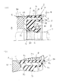
この接触面圧paは、密封対象流体が高圧の場合には、圧力によって密封装置が軸方向押えに軸方向に押し付けられるので、さらに接触面圧が大きくなる。[参考例]図2には参考例に係る密封装置が示されている。
【0035】
この参考例では、リップ状突起12を外周固定部9の密封対象流体側Oに設けたものである。外周固定部9の大気側端部は面取り部13となっている。
【0036】
このリップ状突起12は軸方向密封対象流体側Oに向けて徐々に拡径する方向に傾斜している。このリップ状突起12の付け根位置は金属環3の円筒部31の密封対象流体側端部から軸方向に延びており、その先端は金属環3の円筒部31の密封対象流体側端面を被覆する端面ゴム部54の端面位置よりも大気側Aに位置しており、自由状態ではリップ状突起12と端面ゴム部の外周との間にV字状の空間が形成されている。
【0037】
ハウジング8内周面に接触するリップ状突起12の先端において、密封対象流体側傾斜面とハウジング8内周面と平行の円筒面との成す接触角をα、大気側傾斜面とハウジング8の軸孔8a内周面と平行の円筒面とのなす接触角をβとして、α>βに設定することが好ましい。
【0038】
密封装置1をハウジング8に装着した際には、図2(b)に示すように、外周ゴム部51が径方向に圧縮されると同時に軸方向大気側と密封対象流体側Oに延びて、大気側Aの端部が押え部材10の外径端部の面取り部11内に入り込んで大気側Aの面圧が上がらないが、使用密封対象流体側Oの端部はリップ状突起12によって面圧が確保される。特に、使用中の圧力P0によってリップ状突起12がハウジング8内周に圧接されて、常に強い面圧paを発生させることができるため、外周漏れを防止することができる。
【0039】
その他の構成および作用は上記実施の形態と同様なので、同一の構成部分については同一の符号を付してその説明を省略する。
【0041】
【発明の効果】
以上説明したように、本発明によれば、外周固定部にハウジングの軸孔内周に密接するゴム状弾性材製のリップ状突起を設けたので、外周固定部全体の接触面圧が低下しても、リップ状突起によって外周固定部とハウジング間の隙間がシールされ、外周シール性が向上し、ひいてはシール寿命向上を図ることができる。
【0042】
外周固定部の大気側端部に設けられるリップ状突起を、押え部材端面の面取り部とハウジング内周間の隙間に入り込む構成とすれば、リップ状突起が面取り部によって半径方向外方に向けて押し広げられ、リップ状突起の外周がハウジング内周面に強く圧接され接触面圧が高められる。
【図面の簡単な説明】
【図1】図1は本発明の一実施の形態に係る密封装置を示すもので、同図(a)は要部縦断面、同図(b)は装着状態の部分断面図である。
【図2】図2は参考例に係る密封装置を示すもので、同図(a)は要部縦断面、同図(b)は装着状態の部分断面図である。
【図3】図3は従来の密封装置を示すもので、同図(a)は要部縦断面、同図(b)は装着状態の部分断面図である。
【符号の説明】
1 密封装置
2 リップ状突起
21 傾斜面
22 直交面
3 金属環
31 円筒部
32 内向きフランジ部
4 シールリップ
5 ゴム状弾性体
51 外周ゴム部
52 腰部
53 凹部
54 端面ゴム部
55 内周ゴム部
6 バックアップリング
7 移動軸
8 ハウジング
8a 軸孔
9 外周固定部
10 押え部材
11 面取り部
12 リップ状突起
13 面取り部[0001]
BACKGROUND OF THE INVENTION
The present invention relates to a sealing device used for a shaft seal portion on which a high pressure acts, such as a power steering of an automobile, and more particularly to a seal structure of an outer peripheral fixed portion.
[0002]
[Prior art]
As a conventional high-pressure sealing device of this type, for example, a device as shown in FIG. 3 is known.
[0003]
That is, the outer periphery of the
[0004]
Further, in the case of such a pressure-resistant seal, the atmospheric side end face of the outer
[0005]
The
[0006]
[Problems to be solved by the invention]
However, in the case of the above-described conventional sealing device, the outer
[0007]
Although the
[0008]
If it is always used under the high temperature and high pressure conditions in this state, the outer
[0009]
The present invention has been made in order to solve the above-described problems of the prior art, and an object of the present invention is to provide a sealing device capable of improving the sealing performance of the outer peripheral fixing portion fixed to the housing and thus improving the life. It is to provide.
[0010]
[Means for Solving the Problems]
To achieve the above object, in the present invention, intended to seal a gap between the movable shaft and the inner periphery of the shaft hole of the housing, the inner periphery of the shaft hole of the housing definitive an annular device body periphery, the cylindrical portion And a fitting ring that generates a contact surface pressure at an outer peripheral rubber portion that covers the outer periphery of the cylindrical portion of an L-shaped metal ring that includes an inward flange portion that is provided at the atmospheric end of the cylindrical portion. In the sealing device having the outer periphery fixing portion, the atmosphere side end is connected to the corner portion where the cylindrical portion of the metal ring having an L-shaped cross section and the inward flange portion are connected at the atmosphere side end portion of the outer periphery fixing portion. A lip-shaped protrusion made of a rubber-like elastic material that protrudes to the atmosphere side from the end portion and that is continuous from the outer peripheral rubber portion and is in close contact with the inner periphery of the shaft hole of the housing is provided. parts are contact with exposed inward flange portion of said metal ring , Contact over substantially the entire width in the pressing member end surface to which the inward flange portion is inserted into the shaft hole of the housing, the radially outer end portion of the pressing member end surface chamfered, the gap between the inner periphery of the chamfer and the housing The lip-shaped protrusion fills the gap and is filled with a volume capable of generating contact surface pressure on the inner peripheral surface of the housing, and the lip-shaped protrusion is spread outward in the radial direction by the chamfered portion, and the lip-shaped protrusion The outer periphery of the protrusion is strongly pressed against the inner peripheral surface of the housing to increase the contact surface pressure.
[0011]
A high surface pressure is locally generated between the lip-shaped protrusion and the housing, and the outer peripheral sealability is improved. Even if the contact surface pressure of the entire outer periphery fixing portion decreases, the gap between the outer periphery fixing portion and the housing is sealed by the lip-shaped protrusion.
[0012]
A lip-shaped protrusion is provided at the end on the atmosphere side of the outer peripheral fixing portion.
[0013]
If it does in this way, the seal leak from the outer periphery fitting part of a sealing device will be prevented in the atmosphere side edge part.
[0014]
The end on the atmosphere side of the outer peripheral fixed part abuts on the end face of the presser member inserted into the shaft hole of the housing, the outer diameter end part of the end face of the presser member is chamfered, and the lip is formed in the gap between the chamfered part and the inner periphery of the housing. It is characterized by having a configuration in which the protrusions are filled.
[0015]
In this way, when assembling the actual machine, when the pressing member is abutted against the end face on the atmosphere side of the outer peripheral fixed part, a lip-shaped protrusion is formed in the annular gap formed between the chamfered part of the pressing member and the inner peripheral surface of the housing. The lip-shaped projections are spread outward in the radial direction by the chamfered portion, and the outer periphery of the lip-shaped projections is strongly pressed against the inner peripheral surface of the housing, thereby increasing the contact surface pressure.
[0016]
When the fluid to be sealed is a high pressure, the contact surface pressure is further increased because the sealing device is pressed in the axial direction against the axial presser by the pressure.
[0019]
DETAILED DESCRIPTION OF THE INVENTION
The present invention will be described below based on the illustrated embodiments.
[0020]
FIG. 1 shows a sealing device according to a first embodiment of the present invention.
[0021]
The
[0022]
That is, in the figure, 1 indicates the whole sealing device. The
[0023]
The
[0024]
The rubber-like
[0025]
The outer
[0026]
The axial thickness of the
[0027]
A
[0028]
The outer peripheral fixing
[0029]
The lip-shaped
[0030]
The tip of the lip-shaped
[0031]
On the atmosphere side A of the
[0032]
The volume of the lip-shaped
[0033]
When the
[0034]
When the fluid to be sealed is a high pressure, the contact surface pressure pa further increases the contact surface pressure because the sealing device is pressed against the axial presser by the pressure in the axial direction. [ Reference Example ] FIG. 2 shows a sealing device according to a reference example .
[0035]
In this reference example , the lip-shaped
[0036]
The lip-shaped
[0037]
At the tip of the lip-shaped
[0038]
When the
[0039]
Since other configurations and operations are the same as those of the above-described embodiment, the same components are denoted by the same reference numerals and description thereof is omitted.
[0041]
【The invention's effect】
As described above, according to the present invention, since the lip-shaped protrusion made of rubber-like elastic material that is in close contact with the inner periphery of the shaft hole of the housing is provided on the outer peripheral fixing portion, the contact surface pressure of the entire outer peripheral fixing portion is reduced. However, the gap between the outer peripheral fixing portion and the housing is sealed by the lip-shaped protrusion, so that the outer peripheral sealability is improved, and consequently the seal life can be improved.
[0042]
If the lip-shaped protrusions provided at the end on the atmosphere side of the outer periphery fixing part are configured to enter the gap between the chamfered part of the pressing member end surface and the inner periphery of the housing, the lip-shaped protrusions are directed radially outward by the chamfered part. The outer periphery of the lip-shaped protrusion is strongly pressed against the inner peripheral surface of the housing and the contact surface pressure is increased.
[Brief description of the drawings]
1A and 1B show a sealing device according to an embodiment of the present invention, in which FIG. 1A is a longitudinal sectional view of an essential part, and FIG. 1B is a partial sectional view in a mounted state;
2A and 2B show a sealing device according to a reference example, in which FIG. 2A is a longitudinal sectional view of an essential part, and FIG. 2B is a partial sectional view in a mounted state.
FIGS. 3A and 3B show a conventional sealing device, in which FIG. 3A is a longitudinal sectional view of a main part, and FIG. 3B is a partial sectional view in a mounted state.
[Explanation of symbols]
DESCRIPTION OF
Claims (1)
前記外周固定部の大気側端部における断面L字形状の金属環の前記円筒部と前記内向きフランジ部とが接続された角部に、当該大気側端部よりも大気側に突出し、かつ、前記外周ゴム部から連続して、前記ハウジングの軸孔内周に密接するゴム状弾性材製のリップ状突起を設け、
前記外周固定部の大気側端部は前記金属環の内向きフランジ部が露出しており、当該内向きフランジ部がハウジングの軸孔に差し込まれる押え部材端面にほぼ全幅にわたって当接し、押え部材端面の外径端部には面取りが施され、該面取り部とハウジング内周間の隙間に前記リップ状突起が当該隙間を埋めてハウジング内周面に接触面圧を発生可能なボリュームで充填され、前記リップ状突起が前記面取り部によって半径方向外方に向けて押し広げられ、前記リップ状突起の外周がハウジング内周面に強く圧接され、接触面圧が高められる構成としたことを特徴とする密封装置。It intended to seal the gap between the shaft hole inner periphery and the movement axis of the housing, an annular device body definitive in the inner periphery of the shaft hole of the housing to the outer periphery, inward flange provided on the atmospheric air side end portion of the cylindrical portion and the cylindrical portion In the sealing device having an outer peripheral fixing portion that is fitted and fixed by generating a contact surface pressure in an outer peripheral rubber portion that is covered on an outer periphery of the cylindrical portion of the L-shaped metal ring having a portion,
At the corner where the cylindrical portion of the metal ring having an L-shaped cross section and the inward flange portion at the atmosphere side end of the outer periphery fixing portion is connected, it protrudes to the atmosphere side from the atmosphere side end, and Continuously from the outer peripheral rubber part , provided with a lip-shaped protrusion made of a rubber-like elastic material in close contact with the inner periphery of the shaft hole of the housing,
The end portion on the atmosphere side of the outer peripheral fixing portion has an inward flange portion of the metal ring exposed, and the inward flange portion is in contact with the end surface of the press member inserted into the shaft hole of the housing over almost the entire width. The outer diameter end portion is chamfered, and the lip-shaped protrusion is filled in a gap between the chamfered portion and the housing inner periphery with a volume capable of generating a contact surface pressure on the inner peripheral surface of the housing , The lip-shaped protrusion is pushed and spread outward in the radial direction by the chamfered portion, and the outer periphery of the lip-shaped protrusion is strongly pressed against the inner peripheral surface of the housing to increase the contact surface pressure. Sealing device.
Priority Applications (1)
| Application Number | Priority Date | Filing Date | Title |
|---|---|---|---|
| JP26934497A JP3762529B2 (en) | 1997-09-16 | 1997-09-16 | Sealing device |
Applications Claiming Priority (1)
| Application Number | Priority Date | Filing Date | Title |
|---|---|---|---|
| JP26934497A JP3762529B2 (en) | 1997-09-16 | 1997-09-16 | Sealing device |
Publications (2)
| Publication Number | Publication Date |
|---|---|
| JPH1182751A JPH1182751A (en) | 1999-03-26 |
| JP3762529B2 true JP3762529B2 (en) | 2006-04-05 |
Family
ID=17471081
Family Applications (1)
| Application Number | Title | Priority Date | Filing Date |
|---|---|---|---|
| JP26934497A Expired - Lifetime JP3762529B2 (en) | 1997-09-16 | 1997-09-16 | Sealing device |
Country Status (1)
| Country | Link |
|---|---|
| JP (1) | JP3762529B2 (en) |
Families Citing this family (2)
| Publication number | Priority date | Publication date | Assignee | Title |
|---|---|---|---|---|
| JP2007010009A (en) * | 2005-06-29 | 2007-01-18 | Nsk Ltd | Tight sealing structure and sealed rolling bearing |
| JP6845643B2 (en) * | 2016-09-20 | 2021-03-24 | Kyb株式会社 | shock absorber |
-
1997
- 1997-09-16 JP JP26934497A patent/JP3762529B2/en not_active Expired - Lifetime
Also Published As
| Publication number | Publication date |
|---|---|
| JPH1182751A (en) | 1999-03-26 |
Similar Documents
| Publication | Publication Date | Title |
|---|---|---|
| US4026563A (en) | Oil seal with locking bead and O. D. sealing rib | |
| US7648144B2 (en) | Sealing device | |
| JP3762529B2 (en) | Sealing device | |
| JP3293075B2 (en) | Lip type seal | |
| JP3338189B2 (en) | Reciprocating sealing device | |
| JPH11125337A (en) | Lip type seal | |
| JPH0712762Y2 (en) | Sealing device | |
| JPH0649973Y2 (en) | Oil seal | |
| JPH0446137Y2 (en) | ||
| JPH0571541U (en) | Sealing device | |
| JPH0247311Y2 (en) | ||
| JPH11141688A (en) | Sealing device | |
| JP3533847B2 (en) | Seal ring | |
| JP3785843B2 (en) | Sealing device | |
| JPH0810713Y2 (en) | Sealing device | |
| JPH11351406A (en) | Sealing device | |
| JPH0744855Y2 (en) | Sealing device | |
| JPH0448366Y2 (en) | ||
| JP2003097716A (en) | Sealing device for axle | |
| JP4466842B2 (en) | Sealing device | |
| JPH0225978Y2 (en) | ||
| JPH0720447Y2 (en) | Lip seal | |
| JPH0624270U (en) | Packing | |
| JPH0633261Y2 (en) | Sealing device | |
| JP2545878Y2 (en) | Sealing device |
Legal Events
| Date | Code | Title | Description |
|---|---|---|---|
| A977 | Report on retrieval |
Free format text: JAPANESE INTERMEDIATE CODE: A971007 Effective date: 20040702 |
|
| A131 | Notification of reasons for refusal |
Free format text: JAPANESE INTERMEDIATE CODE: A131 Effective date: 20040720 |
|
| A521 | Written amendment |
Free format text: JAPANESE INTERMEDIATE CODE: A523 Effective date: 20040916 |
|
| A131 | Notification of reasons for refusal |
Free format text: JAPANESE INTERMEDIATE CODE: A131 Effective date: 20050105 |
|
| A521 | Written amendment |
Free format text: JAPANESE INTERMEDIATE CODE: A523 Effective date: 20050302 |
|
| A02 | Decision of refusal |
Free format text: JAPANESE INTERMEDIATE CODE: A02 Effective date: 20050906 |
|
| A521 | Written amendment |
Free format text: JAPANESE INTERMEDIATE CODE: A523 Effective date: 20051101 |
|
| A911 | Transfer of reconsideration by examiner before appeal (zenchi) |
Free format text: JAPANESE INTERMEDIATE CODE: A911 Effective date: 20051107 |
|
| TRDD | Decision of grant or rejection written | ||
| A01 | Written decision to grant a patent or to grant a registration (utility model) |
Free format text: JAPANESE INTERMEDIATE CODE: A01 Effective date: 20051220 |
|
| A61 | First payment of annual fees (during grant procedure) |
Free format text: JAPANESE INTERMEDIATE CODE: A61 Effective date: 20060113 |
|
| R150 | Certificate of patent or registration of utility model |
Free format text: JAPANESE INTERMEDIATE CODE: R150 |
|
| FPAY | Renewal fee payment (event date is renewal date of database) |
Free format text: PAYMENT UNTIL: 20100120 Year of fee payment: 4 |
|
| FPAY | Renewal fee payment (event date is renewal date of database) |
Free format text: PAYMENT UNTIL: 20100120 Year of fee payment: 4 |
|
| FPAY | Renewal fee payment (event date is renewal date of database) |
Free format text: PAYMENT UNTIL: 20110120 Year of fee payment: 5 |
|
| FPAY | Renewal fee payment (event date is renewal date of database) |
Free format text: PAYMENT UNTIL: 20110120 Year of fee payment: 5 |
|
| FPAY | Renewal fee payment (event date is renewal date of database) |
Free format text: PAYMENT UNTIL: 20120120 Year of fee payment: 6 |
|
| FPAY | Renewal fee payment (event date is renewal date of database) |
Free format text: PAYMENT UNTIL: 20130120 Year of fee payment: 7 |
|
| FPAY | Renewal fee payment (event date is renewal date of database) |
Free format text: PAYMENT UNTIL: 20130120 Year of fee payment: 7 |
|
| FPAY | Renewal fee payment (event date is renewal date of database) |
Free format text: PAYMENT UNTIL: 20140120 Year of fee payment: 8 |
|
| S111 | Request for change of ownership or part of ownership |
Free format text: JAPANESE INTERMEDIATE CODE: R313117 |
|
| R350 | Written notification of registration of transfer |
Free format text: JAPANESE INTERMEDIATE CODE: R350 |
|
| EXPY | Cancellation because of completion of term |