JP3748656B2 - Chain tensioner and chain system - Google Patents
Chain tensioner and chain system Download PDFInfo
- Publication number
- JP3748656B2 JP3748656B2 JP07194797A JP7194797A JP3748656B2 JP 3748656 B2 JP3748656 B2 JP 3748656B2 JP 07194797 A JP07194797 A JP 07194797A JP 7194797 A JP7194797 A JP 7194797A JP 3748656 B2 JP3748656 B2 JP 3748656B2
- Authority
- JP
- Japan
- Prior art keywords
- plunger
- chain
- oil
- screw shaft
- chamber
- Prior art date
- Legal status (The legal status is an assumption and is not a legal conclusion. Google has not performed a legal analysis and makes no representation as to the accuracy of the status listed.)
- Expired - Lifetime
Links
Images


Classifications
-
- F—MECHANICAL ENGINEERING; LIGHTING; HEATING; WEAPONS; BLASTING
- F16—ENGINEERING ELEMENTS AND UNITS; GENERAL MEASURES FOR PRODUCING AND MAINTAINING EFFECTIVE FUNCTIONING OF MACHINES OR INSTALLATIONS; THERMAL INSULATION IN GENERAL
- F16H—GEARING
- F16H7/00—Gearings for conveying rotary motion by endless flexible members
- F16H7/08—Means for varying tension of belts, ropes, or chains
- F16H7/0848—Means for varying tension of belts, ropes, or chains with means for impeding reverse motion
-
- F—MECHANICAL ENGINEERING; LIGHTING; HEATING; WEAPONS; BLASTING
- F02—COMBUSTION ENGINES; HOT-GAS OR COMBUSTION-PRODUCT ENGINE PLANTS
- F02B—INTERNAL-COMBUSTION PISTON ENGINES; COMBUSTION ENGINES IN GENERAL
- F02B67/00—Engines characterised by the arrangement of auxiliary apparatus not being otherwise provided for, e.g. the apparatus having different functions; Driving auxiliary apparatus from engines, not otherwise provided for
- F02B67/04—Engines characterised by the arrangement of auxiliary apparatus not being otherwise provided for, e.g. the apparatus having different functions; Driving auxiliary apparatus from engines, not otherwise provided for of mechanically-driven auxiliary apparatus
- F02B67/06—Engines characterised by the arrangement of auxiliary apparatus not being otherwise provided for, e.g. the apparatus having different functions; Driving auxiliary apparatus from engines, not otherwise provided for of mechanically-driven auxiliary apparatus driven by means of chains, belts, or like endless members
-
- F—MECHANICAL ENGINEERING; LIGHTING; HEATING; WEAPONS; BLASTING
- F16—ENGINEERING ELEMENTS AND UNITS; GENERAL MEASURES FOR PRODUCING AND MAINTAINING EFFECTIVE FUNCTIONING OF MACHINES OR INSTALLATIONS; THERMAL INSULATION IN GENERAL
- F16H—GEARING
- F16H7/00—Gearings for conveying rotary motion by endless flexible members
- F16H7/08—Means for varying tension of belts, ropes, or chains
- F16H2007/0802—Actuators for final output members
- F16H2007/0812—Fluid pressure
-
- F—MECHANICAL ENGINEERING; LIGHTING; HEATING; WEAPONS; BLASTING
- F16—ENGINEERING ELEMENTS AND UNITS; GENERAL MEASURES FOR PRODUCING AND MAINTAINING EFFECTIVE FUNCTIONING OF MACHINES OR INSTALLATIONS; THERMAL INSULATION IN GENERAL
- F16H—GEARING
- F16H7/00—Gearings for conveying rotary motion by endless flexible members
- F16H7/08—Means for varying tension of belts, ropes, or chains
- F16H7/0848—Means for varying tension of belts, ropes, or chains with means for impeding reverse motion
- F16H2007/0857—Screw mechanisms
-
- F—MECHANICAL ENGINEERING; LIGHTING; HEATING; WEAPONS; BLASTING
- F16—ENGINEERING ELEMENTS AND UNITS; GENERAL MEASURES FOR PRODUCING AND MAINTAINING EFFECTIVE FUNCTIONING OF MACHINES OR INSTALLATIONS; THERMAL INSULATION IN GENERAL
- F16H—GEARING
- F16H7/00—Gearings for conveying rotary motion by endless flexible members
- F16H7/08—Means for varying tension of belts, ropes, or chains
- F16H7/0848—Means for varying tension of belts, ropes, or chains with means for impeding reverse motion
- F16H2007/0859—Check valves
Landscapes
- Engineering & Computer Science (AREA)
- General Engineering & Computer Science (AREA)
- Mechanical Engineering (AREA)
- Devices For Conveying Motion By Means Of Endless Flexible Members (AREA)
Description
【0001】
【発明の属する技術分野】
この発明は、カム軸駆動用チェーンの張力を一定に保持するチェーンテンショナに関するものである。
【0002】
【従来の技術】
カム軸駆動用のチェーンの張力を一定に保つチェーンテンショナとして、図10に示したものが知られている。このチェーンテンショナはハウジング60に形成されたシリンダ室61内にプランジャ62と、スプリング63とを組み込み、上記スプリング63によって突出性が付与されたプランジャ62によりチェーン64を押圧するようにしている。
【0003】
また、プランジャ62の背部に形成された圧力室65に給油通路66を連通し、その給油通路66にチェックバルブ67を設け、上記プランジャ62が外方向に移動して圧力室65の圧力が低下したとき、チェックバルブ67を開放させ、給油ポンプの駆動により給油通路66から圧力室65に油を流動させるようにしている。
【0004】
ところで、カム軸駆動用のチェーンにおいては、エンジンを停止すると、カム軸に設けられたカムの停止位置の関係から、チェーン64が緊張状態に保持されることがある。この場合、上記チェーンテンショナのプランジャ62は緊張状態のチェーン64により押し込まれるため、圧力室55の油はプランジャ62とシリンダ室61の摺動面からリークし、プランジャ62は後退して、チェーン64の弾力とスプリング63の張力とが釣り合う位置に保持される。
【0005】
このため、エンジンの再始動によりチェーン64に弛みが生じると、プランジャ62は外方向に大きく移動する。このとき、油圧ポンプは始動直後であって吐出量が少ないため、圧力室65に充分な油を供給することができず、圧力室65に空気が侵入してダンピング特性が低下し、異音が発生することがある。
【0006】
また、低温始動時には、油の粘度が高く、流動性が悪いため、上記と同様の問題が生じる。
【0007】
上記のような問題点を解決するため、実開昭64−25557号公報に記載されたチェーンテンショナにおいては、プランジャの外周にラックを設け、ハウジングにラチェット爪を揺動自在に取付け、そのラチェット爪のラックに対する係合によりプランジャの後退動を防止するようにしている。
【0008】
【発明が解決しようとする課題】
ところで、上記公報に記載されたチェーンテンショナにおいては、ラックとラチェット爪の係合部にチェーンからの荷重を受けるため、耐久性に問題がある。また、プランジャが外方向に移動するとき、ラチェット爪がラックと係脱するため、異音が発生するという問題がある。
【0009】
この発明の第1の課題は、エンジンの再始動時および作動油の流動性が悪い低温始動時にチェーンの押込み力を緩衝する圧力室に空気が侵入するのを防止することができると共に、異音の発生のない耐久性に優れた小型のチェーンテンショナを提供することである。
【0010】
また、この発明の第2の課題は、騒音の発生の少ないチェーンシステムを提供することである。
【0011】
【課題を解決するための手段】
上記の第1の課題を解決するために、この発明に係るチェーンテンショナにおいては、ハウジングに形成されたシリンダ室内に摺動可能なチェーン押圧用のプランジャと、そのプランジャに外方向への突出性を付与するスプリングとを組込み、ハウジングには前記プランジャの背部に形成された圧力室に連通する給油通路を設けたチェーンテンショナにおいて、前記プランジャにオリフィスを介して外部に連通する油室と、後端からその油室に連通するねじ孔とを設け、そのねじ孔にねじ軸をねじ係合し、上記油室内に前記スプリングを組込んでねじ軸とプランジャとを離反する方向に押圧し、かつプランジャを回り止めし、上記ねじ孔およびねじ軸のねじ山を、プランジャの押し込み力を受ける圧力側フランクのフランク角が遊び側フランクのフランク角より大きい鋸歯状とし、その鋸歯状ねじ山に前記スプリングの弾力によってプランジャに対しねじ軸が回転しつつ離反する方向に移動するリード角を設けた構成を採用したのである。
ここで、前記給油通路の油出口部に圧力室への油の流入を許容して逆流するのを防止するチェックバルブを設けておくのが好ましい。
【0016】
また、第2の課題を解決するため、この発明に係るチェーンシステムにおいては、クランクシャフトの回転をカムシャフトに伝えるチェーンの弛み側チェーンを上記発明のチェーンテンショナにおけるプランジャで押圧した構成を採用している。
【0017】
【作用】
上記のように、ねじ孔にねじ軸をねじ係合したことにより、エンジンの停止時におけるチェーンの張力増大時、プランジャに作用する軸方向の押し込み力をねじ軸とねじ孔のねじ係合部で受けることができる。このため、プランジャは押し込まれず、エンジンが再始動されてチェーンに弛みが生じても、プランジャの外方向への移動量が小さく、圧力室に外部の空気が侵入したり、油に含まれる空気が油中より析出するのを防止することができる。
【0018】
【発明の実施の形態】
以下、この発明の実施の形態を図1乃至9に基づいて説明する。
【0019】
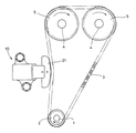
図1に示すように、クランクシャフト1の端部に取付けられたスプロケット2の回転はチェーン3を介してカムシャフト4の端部に取付けられたスプロケット5に伝達される。
【0020】
上記チェーン3の弛み側チェーン3aはチェーンテンショナ10によって押圧され、その押圧によってチェーン3は一定の張力に保持される。
【0021】
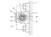
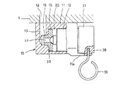
図2および図3はチェーンテンショナを示す。このチェーンテンショナは、シリンダブロック4のクランク室の壁面にボルト止めされたハウジング11を有する。
【0022】
ハウジング11にはシリンダ室12と、そのシリンダ室12の閉塞端において開口する給油通路13とが設けられている。給油通路13の形成に際し、ここでは、シリンダ室12の閉塞端に嵌合孔14を形成し、その嵌合孔14にシート板15の片面に設けた軸部16に圧入し、上記シート板15に油出口17を形成している。この給油通路13は、図4に示すように、シリンダブロック4に形成された給油孔18と連通して油が供給される。
【0023】
前記シリンダ室12はハウジング11の一端面で開口し、そのシリンダ室12にプランジャ19がスライド自在に挿入されている。また、プランジャ19は、図4に示すように、ハウジング11に設けたガイド片11aによって回り止めされている。
【0024】
上記プランジャ19の組込みによって、ハウジング11の内部に圧力室20が形成される。
【0025】
プランジャ19のハウジング11の外部に臨む先端部には、チェーン押圧用のスリッパ21が取付けられている。スリッパ21の内部には金属製の環状の板体22がモールドされ、その板体22の外周囲に内部と外部とを連通させる間隙23が設けられている。
【0026】
上記スリッパ21は、プランジャ19の先端部に対する上記板体22の圧入によって取付けられている。
【0027】
プランジャ19は筒状をなし、その先端部内側に対する栓体24の圧入によってプランジャ19の内部に油室25が形成される。油室25は、栓体24の外周に設けた螺旋状のオリフィス26、およびスリッパ21の内部に形成された上記間隙23を介して外部と連通している。
【0028】
また、プランジャ19の後端部には、上記油室25に連通するねじ孔27が設けられ、そのねじ孔27にねじ軸28がねじ係合されている。
【0029】
ねじ軸28は、先端面で開口す軸方向の孔29を有し、その孔29内にスプリングシート30とスプリング31とが組込まれ、上記スプリング31によってねじ軸28とプランジャ19とは相反する方向に押圧されている。スプリングシート30は球面32を有し、その球面32が孔29の閉塞端面に接触している。
【0030】
尚、スプリングシート30は、スプリング31と栓体24との間に組込んで栓体24の端面に球面を接触させるようにしてもよい。
【0031】
前記ねじ軸28の後端部には球形の弁体33が取付けられている、この弁体33は給油通路13の油出口17に設けた円錐形シート面34に対して接触、離反可能とされ、上記シート面34に対する接触により給油通路13を閉じる。
【0032】
前記プランジャ19に形成されたねじ孔27およびそのねじ孔27にねじ係合されたねじ軸28のねじ山は、プランジャ19の押し込み力を受ける圧力側フランク35のフランク角が遊び側フランク角より大きい鋸歯状とされ、上記フランク角とリード角の関係からプランジャ19は突出方向に弛み条件とされ、押し込み方向にはロック条件とされている。
【0033】
ここで、弛み条件とは、スプリング31の弾力によってプランジャ19がねじ軸28に対し、遊び側フランクとリード角の関係から離反する方向に速やかに移動することをいう。
また、ロック条件とは、チェーンからプランジャ19に静荷重が負荷されてプランジャ19が押し込まれても、圧力側フランク35の接触面に作用する摩擦力によりプランジャ19がロックしてシリンダ室12内に向けて移動せず、チェーンの振動がプランジャ19に作用した時、プランジャ19がねじ係合面間に形成された軸方向隙間において接触、離反を操り返し、押し込み力とスプリング31の弾力とが釣り合う位置まで後退動することを言う。
【0034】
なお、プランジャ19が軸方向に移動する時、そのプランジャ19はガイド片11aによって回り止めされているため、ねじ軸28が回転する。
【0035】
また、プランジャ19を突出方向に弛み条件とし、押し込み方向にロック条件としたことにとり、ねじ軸28は油室25内に向けての移動はロック条件とされ、シリンダ室12の閉塞端に向けての移動は弛み条件とされる。
【0036】
上記の構成から成るチェーンテンショナは、プランジャ19をシリンダ室12内に押し込み、その押し込み状態を保持してシリンダブロック4のクランク室の壁面にハウジング11をボルト止めする。
【0037】
図4は、プランジャ19を押し込み状態に保持する機構の一例を示し、ハウジング11に設けた前記ガイド11aとスリッパ21の側面とにピン孔38を形成し、プランジャ19の押し込みより両ピン孔38を一致させピン39を差し込むようにしている。このとき、弁体33はシート面34に密着する状態にある。ハウジング11の取付け後、ピン39を引き抜くと、スプリング31の弾力により、プランジャ19が外方向に移動し、その移動によってねじ軸28は弁体33がシート面34に密着する状態を維持しつつ回転する。また、プランジャ19の外方向への移動により、スリッパ21が弛み側チェーン3aを押圧し、チェーン3が一定の張力に保持される。
【0038】
上記のようなチェーンテンショナの取付け状態において、エンジンを始動し、クランクシャフト1の端部に取付けられたスプロケット2の矢印方向の回転によってチェーン3に緩みが弛みが生じると、給油通路13に供給される油の圧力によって、プランジャ19およびねじ軸28が外方向に移動し、その移動によって弁体33がシート面34から離反するため、給油通路13の油は圧力室20に流入する。
【0039】
プランジャ19の外方向への移動によってスリッパ21がチェーン3を押すため、チェーン3のたるみは吸収されると共に、スプリング31の弾力により、ねじ軸28は回転しつつシリンダ室12の閉塞端に向けて移動して、弁体33がシート面34に密着し、プランジャ19とねじ軸28の相対的な軸方向の移動停止によりチェーン3は所定の張力に保持される。ここで、ねじ軸28はねじの作用によって回転しつつ軸方向に移動するため、異音が発生するということはない。
【0040】
エンジンを停止すると、カムシャフトに設けられたカムの停止位置の関係からチェーン3の弛み側チェーン3aが緊張する場合がある。この場合、プランジャ19はチェーン3によって押圧されるが、プランジャ19は、ねじ軸28とねじ孔27のねじ山におけるフランク角とリード角の関係から押し込み方向にロック条件されているため、プランジャ19は押し込まれない。
【0041】
このため、エンジンの停止後、エンジンが再始動されてチェーン3の弛み側チェーン3aに弛みが生じても、プランジャ19の突出量は少なく、圧力室20の圧力低下も少ないため、圧力室20内に外部の空気が侵入せず、また、圧力室20内の油から空気が析出するのを防止することができる。
【0042】
なお、低温始動時、油の粘度が高く、圧力室20への油の流入が悪いが、この場合でもねじ軸15の突出量が小さいため、圧力室20に空気が侵入するのを妨止することができる。
【0043】
因みに、エンジン始動時におけるスリッパ21の変位置を測定したところ、図5に示す測定結果を得た。そのグラフから明らかなように、スリッパ21およびチェーン3のバタツキが殆んどなく、異音の発生の少ないことが判る。
【0044】
また、チェーン3はエンジンの始動、停止に関係なく常に略一定の弾力に保持されるため、エンジンの運転後におけるチェーン3の伸びは比較的少ない。
【0045】
なお、チェーン2が緊張してプランジャ19を押圧するとき、その押圧力がスプリング31と給油通路13に供給される油の圧力の合力より大きい場合、プランジャ19はシリンダ室12内に向けてゆっくりと移動し、スプリング31と給油通路13に供給される油の圧力の合力と、チェーン3がプランジャ19を押圧する押し込み力とが釣り合うと、プランジャ19は停止する。
【0046】
プランジャ19が押し込められるとき、圧力室20の油はプランジャ19とシリンダ室12の摺動面間に形成されたリーク隙間から外部にリークされると共に、油室25内の油はオリフィス26およびスリッパ21の内部に形成された間隙23から外部にリークされる。このとき、油中に空気が混入していると、油のリークと共に空気も外部に排出される。
【0047】
なお、実施の形態では、給油孔18から給油通路13に油を供給するようにしたが、ハウジング11の上面で開口するリザーバ室を形成し、カムシャフト4を給油した油をシリンダ壁により上記リザーバ室に導いて貯溜し、その油を給油通路13に流入させるようにしてもよい。
【0048】
図6は、この発明の他の実施の形態を示す。この実施の形態においては、ねじ軸28の後端に設けたテーパ面28aをシート板15の油出口17に形成されたシート面34に対して接触、離反自在としている。
【0049】
また、ねじ軸28に後端面から孔29に連通する通路40を形成し、その通路40の油出口側の端部にチェックバルブ41を設け、このチェックバルブ41の開閉量をハット形の孔あきリテーナ42によって制限している。
【0050】
さらに、スプリング31の栓体24側の端部にスプリングシート30を組込んでいる。
【0051】
他の構成は、先に述べた図2の発明の実施の形態と同一であるため、同一部品に同一の符号を付して説明を省略する。
【0052】
上記の構成から成るチェーンテンショナにおいては、チェーン3がスリッパ21を押圧して、プランジャ19が後退したとき、チェックバルブ41によって給油通路13の油出口17を閉じ、油室25内の油をオリフィス26およびスリッパ21の内部の間隙23から外部にリークさせると共に、圧力室20内の油をシリンダ室12とプランジャ19の摺動面間より外部にリークさせる。
【0053】
また、チェーン3に弛みが生じたとき、スプリング31の弾圧によりプランジャ19を外方向に移動させ、油室25内の圧力低下によりプランジャ19を外方向に移動させ、油室25内の圧力低下によりチェックバルブ41を開放させて給油通路13に供給される油を油室25に流入させる。
【0054】
ここで、プランジャ19の外方向への移動は弛み条件であるため、プランジャ19は急速に外方向に移動して、チェーン3の弛みを吸収し、スプリング31の弾力と給油通路13に供給される油の圧力の合力とチェーン3がスリッパ21を押圧する押圧力とが釣り合うと、プランジャ19は停止する。
【0055】
なお、図6では、プランジャ19の油室25内にチェックバルブ41およびリテーナ42を組み込んだが、図7に示すように、シート板15の油出口17に収納凹部45を形成し、その収納凹部45内にチェックバルブ41およびリテーナ42を組み込んで筒状のリテーナ押え47の圧入によりリテーナ42を抜け止めしてもよい。
【0056】
また、図8に示すように、シリンダ室12の閉塞端部に嵌合したシート板48の油出口17に段付きの収納凹部49を形成し、その収納凹部49に上記油出口17を開閉するチェックバルブ41を組み込み、そのチェックバルブ41を上記収納凹部49の大径部に圧入した板状の孔あきリテーナ50によって開閉量を規制してもよい。
【0057】
なお、図8に示す実施の形態においては、ハウジング11の外周面から圧力室20に連通する孔51を設け、その孔51に圧入した栓体52の外周に螺旋状のオリフィス53を形成しており、圧力室20の油中に気泡が発生した場合、プランジャ19の後退動によって上記気泡をオリフィス53から排出させるようにしている。
【0058】
図7および図8に示すように、シート板15、48にチェックバルブ41およびリテーナ42、50を組み込むことにより、シート板15、48に対するチェックバルブ41およびリテーナ42、50の組み込みは、ハウジング11の外部において行うことができ、その組み込み後、シート板15、48をシリンダ室12内に組み込むことにより、チェックバルブ41およびリテーナ42、50も同時に組付けられるため、組立が容易である。
【0059】
図9はこの発明のさらに他の実施の形態を示す。この実施の形態においては、プランジャ19の先端内部側に圧入した栓体24に鍔54を設け、その鍔54が衝合するプランジャ19の先端面に栓体24の外周面に形成されたオリフィス26と連通する半径方向の溝55を形成している。
【0060】
他の構成は、図2に示すチェーンテンショナと同一の構成であるため、同一部品には同一の符号を付して説明を省略する。
【0061】
上記実施の形態においては、プランジャ19が押し込められたとき、油室25の油はオリフィス26から溝55に流れて外部にリークするため、油室内の油をスムーズにリークさせることができる。
【0062】
なお、図7乃至図9に示すチェーンテンショナにおいては、突出性が付与されたプランジャ19によって揺動自在に支持されたスリッパ56を押し、そのスリッパ56を介してチェーン3を押圧する。
【0063】
【発明の効果】
以上のように、この発明においては、エンジンの停止によってチェーンが緊張し、そのチェーンの緊張によってプランジャに押し込み力が作用してもプランジャがロックして押し込まれることがないため、エンジンの再始動あるいは低温始動時にチェーンに弛みが生じても、プランジャの突出量が少なく、圧力室や油室への空気の侵入することができると共に、プランジャはねじの作用によって軸方向に移動するため、異音の発生の少ない耐久性に優れたチェーンテンショナを提供することができる。
【0064】
また、プランジャの後端部に形成したねじ孔にねじ軸をねじ係合して、ねじ軸の先端部をプランジャの油室内に位置させた構成であるため、チェーンテンショナの軸方向長さが短く、小型コンパクトなチェーンテンショナを提供することができる。
【0065】
さらに、エンジンの始動時においてスリッパおよびチェーンがバタつくのを防止することができ、騒音の少ないチェーンシステムを形成することができる。
【図面の簡単な説明】
【図1】この発明に係るチェーンテンショナの使用状態を示す断面図
【図2】同上チェーンテンショナの断面図
【図3】図2のIII −III 線に沿った断面図
【図4】同上のプランジャの押し込み状態を示す一部切欠平面図
【図5】エンジン始動時のスリッパの変位量を示すグラフ
【図6】この発明に係るチェーンテンショナの他の例を示す断面図
【図7】この発明に係るチェーンテンショナの他の例を示す断面図
【図8】この発明に係るチェーンテンショナの他の例を示す断面図
【図9】この発明に係るチェーンテンショナのさらに他の例を示す断面図
【図10】従来のチェーンテンショナを示す断面図
【符号の説明】
11 ハウジング
12 シリンダ室
13 給油通路
19 プランジャ
20 圧力室
21 スリッパ
25 油室
27 ねじ孔
28 ねじ軸
31 スプリング
33 弁体
35 圧力側フランク
36 遊び側フランク
40 通路
41 チェックバルブ[0001]
BACKGROUND OF THE INVENTION
The present invention relates to a chain tensioner that maintains a constant tension of a camshaft drive chain.
[0002]
[Prior art]
As a chain tensioner that keeps the tension of the chain for driving the camshaft constant, the one shown in FIG. 10 is known. This chain tensioner incorporates a
[0003]
Further, an
[0004]
By the way, in the camshaft drive chain, when the engine is stopped, the
[0005]
For this reason, when the
[0006]
Further, at the time of starting at low temperature, the oil has a high viscosity and poor fluidity, so that the same problem as described above occurs.
[0007]
In order to solve the above problems, in the chain tensioner described in Japanese Utility Model Publication No. 64-25557, a rack is provided on the outer periphery of the plunger, and a ratchet claw is swingably attached to the housing. The plunger is prevented from moving backward by engagement with the rack.
[0008]
[Problems to be solved by the invention]
By the way, in the chain tensioner described in the above publication, there is a problem in durability because the load from the chain is received by the engaging portion between the rack and the ratchet pawl. Further, when the plunger moves outward, the ratchet pawl is engaged with or disengaged from the rack, so that there is a problem that abnormal noise is generated.
[0009]
The first problem of the present invention is that air can be prevented from entering the pressure chamber that buffers the pushing force of the chain at the time of restarting the engine and low temperature starting when the fluidity of the hydraulic oil is poor, It is an object of the present invention to provide a small-sized chain tensioner that is excellent in durability and does not cause the occurrence of the occurrence of a crack.
[0010]
A second object of the present invention is to provide a chain system that generates less noise.
[0011]
[Means for Solving the Problems]
In order to solve the above first problem, in the chain tensioner according to the present invention, a plunger for pressing a chain that is slidable in a cylinder chamber formed in the housing, and the plunger has an outward projecting property. A chain tensioner that incorporates a spring to be applied and has a housing provided with an oil supply passage that communicates with a pressure chamber formed on the back of the plunger, and an oil chamber that communicates with the plunger through an orifice, and a rear end. A screw hole that communicates with the oil chamber, a screw shaft is screw-engaged with the screw hole, the spring is assembled into the oil chamber, the screw shaft and the plunger are pressed away from each other, and the plunger is The flank angle of the pressure side flank that receives the pushing force of the plunger is set to the play side flank. Of the flank angle greater than the sawtooth it is had adopted a structure in which a lead angle relative to the plunger by the elastic force of the spring to its serrated thread screw shaft moves in the direction away while rotating.
Here, it is preferable to provide a check valve at the oil outlet portion of the oil supply passage to allow the oil to flow into the pressure chamber and prevent backflow.
[0016]
In order to solve the second problem, the chain system according to the present invention employs a configuration in which the slack side chain of the chain that transmits the rotation of the crankshaft to the camshaft is pressed by the plunger in the chain tensioner of the present invention. Yes.
[0017]
[Action]
As described above, when the screw shaft is screw-engaged with the screw hole, the axial pushing force acting on the plunger is increased between the screw shaft and the screw engaging portion of the screw hole when the chain tension is increased when the engine is stopped. Can receive. For this reason, even if the plunger is not pushed in and the engine is restarted and the chain becomes slack, the amount of outward movement of the plunger is small, and external air enters the pressure chamber or air contained in the oil Precipitation from oil can be prevented.
[0018]
DETAILED DESCRIPTION OF THE INVENTION
Hereinafter, an embodiment of the present invention will be described with reference to FIGS.
[0019]
As shown in FIG. 1, the rotation of the sprocket 2 attached to the end of the
[0020]
The slack side chain 3a of the
[0021]
2 and 3 show a chain tensioner. This chain tensioner has a
[0022]
The
[0023]
The
[0024]
By incorporating the
[0025]
A
[0026]
The
[0027]
The
[0028]
Further, a
[0029]
The
[0030]
The
[0031]
A
[0032]
The
[0033]
Here, the slack condition, means that the
Further, the lock condition is that even if a static load is applied from the chain to the
[0034]
When the
[0035]
Further, the
[0036]
The chain tensioner configured as described above pushes the
[0037]
FIG. 4 shows an example of a mechanism for holding the
[0038]
When the chain tensioner is attached as described above, when the engine is started and the
[0039]
Since the
[0040]
When the engine is stopped, the slack side chain 3a of the
[0041]
For this reason, even if the engine is restarted after the engine is stopped and the slack side chain 3a of the
[0042]
In addition, at the time of cold start, the viscosity of the oil is high and the inflow of the oil into the
[0043]
Incidentally, when the displacement position of the
[0044]
Further, since the
[0045]
When the chain 2 is tensioned and presses the
[0046]
When the
[0047]
In the embodiment, oil is supplied from the
[0048]
FIG. 6 shows another embodiment of the present invention. In this embodiment, the
[0049]
Further, a
[0050]
Further, a
[0051]
Since other configurations are the same as those of the embodiment of the invention shown in FIG. 2 described above, the same components are denoted by the same reference numerals and description thereof is omitted.
[0052]
In the chain tensioner configured as described above, when the
[0053]
Further, when the
[0054]
Here, since the outward movement of the
[0055]
In FIG. 6, the
[0056]
Further, as shown in FIG. 8, a stepped
[0057]
In the embodiment shown in FIG. 8, a
[0058]
As shown in FIGS. 7 and 8, by incorporating the
[0059]
FIG. 9 shows still another embodiment of the present invention. In this embodiment, a
[0060]
Since the other configuration is the same as that of the chain tensioner shown in FIG. 2, the same components are denoted by the same reference numerals and description thereof is omitted.
[0061]
In the above embodiment, when the
[0062]
In the chain tensioner shown in FIG. 7 to FIG. 9, the
[0063]
【The invention's effect】
As described above, in the present invention, the chain is tensioned by stopping the engine, and even if a pushing force is applied to the plunger by the tension of the chain, the plunger is not locked and pushed. Even if the chain becomes slack during cold start, the amount of protrusion of the plunger is small, air can enter the pressure chamber and oil chamber, and the plunger moves in the axial direction by the action of the screw. It is possible to provide a chain tensioner that is less likely to generate and has excellent durability.
[0064]
In addition, since the screw shaft is screw-engaged with the screw hole formed at the rear end of the plunger and the tip of the screw shaft is positioned in the oil chamber of the plunger, the axial length of the chain tensioner is short. A small and compact chain tensioner can be provided.
[0065]
Furthermore, it is possible to prevent the slipper and the chain from fluttering when the engine is started, and a chain system with less noise can be formed.
[Brief description of the drawings]
1 is a cross-sectional view of a chain tensioner according to the present invention in use. FIG. 2 is a cross-sectional view of the same chain tensioner. FIG. 3 is a cross-sectional view taken along line III-III in FIG. FIG. 5 is a graph showing the amount of slipper displacement when the engine is started. FIG. 6 is a cross-sectional view showing another example of the chain tensioner according to the present invention. FIG. 8 is a cross-sectional view showing another example of a chain tensioner according to the present invention. FIG. 9 is a cross-sectional view showing still another example of the chain tensioner according to the present invention. 10] Cross-sectional view of a conventional chain tensioner [Explanation of symbols]
11
Claims (3)
を防止するチェックバルブを設けた請求項1に記載のチェーンテンショナ。The chain tensioner according to claim 1, wherein a check valve is provided at an oil outlet portion of the oil supply passage to allow the oil to flow into the pressure chamber and prevent backflow.
ェーンを請求項1又は2に記載のチェーンテンショナのプランジャで押圧したチェーンシ
ステム。The chain system which pressed the slack side chain of the chain which transmits rotation of a crankshaft to a camshaft with the plunger of the chain tensioner of Claim 1 or 2.
Priority Applications (1)
| Application Number | Priority Date | Filing Date | Title |
|---|---|---|---|
| JP07194797A JP3748656B2 (en) | 1996-03-29 | 1997-03-25 | Chain tensioner and chain system |
Applications Claiming Priority (5)
| Application Number | Priority Date | Filing Date | Title |
|---|---|---|---|
| JP7581896 | 1996-03-29 | ||
| JP23284896 | 1996-09-03 | ||
| JP8-232848 | 1996-09-03 | ||
| JP8-75818 | 1996-09-03 | ||
| JP07194797A JP3748656B2 (en) | 1996-03-29 | 1997-03-25 | Chain tensioner and chain system |
Publications (2)
| Publication Number | Publication Date |
|---|---|
| JPH10132039A JPH10132039A (en) | 1998-05-22 |
| JP3748656B2 true JP3748656B2 (en) | 2006-02-22 |
Family
ID=27300819
Family Applications (1)
| Application Number | Title | Priority Date | Filing Date |
|---|---|---|---|
| JP07194797A Expired - Lifetime JP3748656B2 (en) | 1996-03-29 | 1997-03-25 | Chain tensioner and chain system |
Country Status (1)
| Country | Link |
|---|---|
| JP (1) | JP3748656B2 (en) |
Cited By (1)
| Publication number | Priority date | Publication date | Assignee | Title |
|---|---|---|---|---|
| US8393987B2 (en) | 2008-10-22 | 2013-03-12 | Ntn Corporation | Chain tensioner |
Families Citing this family (8)
| Publication number | Priority date | Publication date | Assignee | Title |
|---|---|---|---|---|
| JP3683102B2 (en) * | 1997-09-30 | 2005-08-17 | Ntn株式会社 | Chain tensioner |
| JP3712550B2 (en) * | 1999-01-04 | 2005-11-02 | Ntn株式会社 | Chain tensioner |
| JP2006250362A (en) * | 2006-06-14 | 2006-09-21 | Ntn Corp | Chain tensioner |
| JP4806314B2 (en) * | 2006-08-24 | 2011-11-02 | Ntn株式会社 | Chain tensioner |
| DE102007023671B4 (en) | 2006-06-15 | 2023-03-16 | Ntn Corp. | chain tensioner |
| JP4732308B2 (en) * | 2006-11-21 | 2011-07-27 | Ntn株式会社 | Chain tensioner |
| JP5122876B2 (en) * | 2007-07-03 | 2013-01-16 | Ntn株式会社 | Chain tensioner manufacturing method |
| EP2280190B1 (en) | 2009-07-14 | 2012-09-19 | NTN Corporation | Chain tensioner |
-
1997
- 1997-03-25 JP JP07194797A patent/JP3748656B2/en not_active Expired - Lifetime
Cited By (1)
| Publication number | Priority date | Publication date | Assignee | Title |
|---|---|---|---|---|
| US8393987B2 (en) | 2008-10-22 | 2013-03-12 | Ntn Corporation | Chain tensioner |
Also Published As
| Publication number | Publication date |
|---|---|
| JPH10132039A (en) | 1998-05-22 |
Similar Documents
| Publication | Publication Date | Title |
|---|---|---|
| US5713809A (en) | Chain tensioner and chain system | |
| JP3926182B2 (en) | Ratchet hydraulic tensioner | |
| JP3670911B2 (en) | Chain tensioner | |
| JP3748656B2 (en) | Chain tensioner and chain system | |
| US5314388A (en) | Oil-operated tensioner with air bleeding mechanism | |
| JPH10122315A (en) | Automatic tensioner | |
| US20030134703A1 (en) | Ratchet-type hydraulic tensioner | |
| GB2422415A (en) | Hydraulic tensioner having a friction ring | |
| JP3687956B2 (en) | Ratchet tensioner with pressure oil chamber | |
| JP4435757B2 (en) | Chain tensioner mounting device | |
| JP2001082558A (en) | Chain tensioner | |
| JP3635188B2 (en) | Chain tensioner and chain system | |
| JP3590221B2 (en) | Chain tensioners and chain systems | |
| JP4072306B2 (en) | Hydraulic chain tensioner | |
| JP4898403B2 (en) | Chain tensioner | |
| JPH109350A (en) | Chain tensioner | |
| JP4017427B2 (en) | Hydraulic tensioner lifter | |
| JP3705945B2 (en) | Chain tensioner | |
| JPH11201245A (en) | Chain tensioner | |
| JP3602706B2 (en) | Chain tensioner | |
| JP2002364720A (en) | Chain tensioner | |
| JP2000291750A (en) | Chain tensioner | |
| JP3560735B2 (en) | Chain tensioner | |
| JP3712468B2 (en) | Chain tensioner | |
| JP3635192B2 (en) | Chain tensioner |
Legal Events
| Date | Code | Title | Description |
|---|---|---|---|
| A131 | Notification of reasons for refusal |
Free format text: JAPANESE INTERMEDIATE CODE: A131 Effective date: 20040907 |
|
| A521 | Written amendment |
Free format text: JAPANESE INTERMEDIATE CODE: A523 Effective date: 20041105 |
|
| A131 | Notification of reasons for refusal |
Free format text: JAPANESE INTERMEDIATE CODE: A131 Effective date: 20041214 |
|
| A521 | Written amendment |
Free format text: JAPANESE INTERMEDIATE CODE: A523 Effective date: 20050210 |
|
| A02 | Decision of refusal |
Free format text: JAPANESE INTERMEDIATE CODE: A02 Effective date: 20050802 |
|
| A521 | Written amendment |
Free format text: JAPANESE INTERMEDIATE CODE: A523 Effective date: 20050930 |
|
| A911 | Transfer of reconsideration by examiner before appeal (zenchi) |
Free format text: JAPANESE INTERMEDIATE CODE: A911 Effective date: 20051005 |
|
| TRDD | Decision of grant or rejection written | ||
| A01 | Written decision to grant a patent or to grant a registration (utility model) |
Free format text: JAPANESE INTERMEDIATE CODE: A01 Effective date: 20051115 |
|
| A61 | First payment of annual fees (during grant procedure) |
Free format text: JAPANESE INTERMEDIATE CODE: A61 Effective date: 20051129 |
|
| R150 | Certificate of patent or registration of utility model |
Free format text: JAPANESE INTERMEDIATE CODE: R150 |
|
| FPAY | Renewal fee payment (event date is renewal date of database) |
Free format text: PAYMENT UNTIL: 20081209 Year of fee payment: 3 |
|
| FPAY | Renewal fee payment (event date is renewal date of database) |
Free format text: PAYMENT UNTIL: 20091209 Year of fee payment: 4 |
|
| FPAY | Renewal fee payment (event date is renewal date of database) |
Free format text: PAYMENT UNTIL: 20101209 Year of fee payment: 5 |
|
| FPAY | Renewal fee payment (event date is renewal date of database) |
Free format text: PAYMENT UNTIL: 20101209 Year of fee payment: 5 |
|
| FPAY | Renewal fee payment (event date is renewal date of database) |
Free format text: PAYMENT UNTIL: 20111209 Year of fee payment: 6 |
|
| FPAY | Renewal fee payment (event date is renewal date of database) |
Free format text: PAYMENT UNTIL: 20111209 Year of fee payment: 6 |
|
| FPAY | Renewal fee payment (event date is renewal date of database) |
Free format text: PAYMENT UNTIL: 20121209 Year of fee payment: 7 |
|
| FPAY | Renewal fee payment (event date is renewal date of database) |
Free format text: PAYMENT UNTIL: 20121209 Year of fee payment: 7 |
|
| FPAY | Renewal fee payment (event date is renewal date of database) |
Free format text: PAYMENT UNTIL: 20131209 Year of fee payment: 8 |
|
| R250 | Receipt of annual fees |
Free format text: JAPANESE INTERMEDIATE CODE: R250 |
|
| R250 | Receipt of annual fees |
Free format text: JAPANESE INTERMEDIATE CODE: R250 |
|
| R250 | Receipt of annual fees |
Free format text: JAPANESE INTERMEDIATE CODE: R250 |
|
| EXPY | Cancellation because of completion of term |