JP3746097B2 - How to stabilize the track by tamping under the sleepers - Google Patents
How to stabilize the track by tamping under the sleepers Download PDFInfo
- Publication number
- JP3746097B2 JP3746097B2 JP02025596A JP2025596A JP3746097B2 JP 3746097 B2 JP3746097 B2 JP 3746097B2 JP 02025596 A JP02025596 A JP 02025596A JP 2025596 A JP2025596 A JP 2025596A JP 3746097 B2 JP3746097 B2 JP 3746097B2
- Authority
- JP
- Japan
- Prior art keywords
- tamping
- rail
- track
- stabilization
- load pressure
- Prior art date
- Legal status (The legal status is an assumption and is not a legal conclusion. Google has not performed a legal analysis and makes no representation as to the accuracy of the status listed.)
- Expired - Fee Related
Links
Images


Classifications
-
- E—FIXED CONSTRUCTIONS
- E01—CONSTRUCTION OF ROADS, RAILWAYS, OR BRIDGES
- E01B—PERMANENT WAY; PERMANENT-WAY TOOLS; MACHINES FOR MAKING RAILWAYS OF ALL KINDS
- E01B27/00—Placing, renewing, working, cleaning, or taking-up the ballast, with or without concurrent work on the track; Devices therefor; Packing sleepers
- E01B27/12—Packing sleepers, with or without concurrent work on the track; Compacting track-carrying ballast
- E01B27/13—Packing sleepers, with or without concurrent work on the track
- E01B27/16—Sleeper-tamping machines
- E01B27/17—Sleeper-tamping machines combined with means for lifting, levelling or slewing the track
Abstract
Description
【0001】
【発明の属する技術分野】
本発明は、軌框を暫定的な目標位置へ上昇してステップ・バイ・ステップ式に枕木下を突固める一方、作業方向で見て突固め現場の後方で軌框を、軌道長手方向に対して水平方向及び垂直方向に振動させると共に軌框降下値を形成するように該軌框を鉛直方向の荷重圧で負荷し、ひいては最終目標位置へ降下させるようにする形式の、枕木下を突固めて軌框を安定化する方法に関するものである。
【0002】
【従来の技術】
米国特許第5172635号明細書に基づいて公知になっている前記形式の方法では、枕木下突固めの範囲内で得られる軌框位置誤差補正動作と、これに続いて行われるところの、鉛直方向の荷重圧並びに水平方向の軌框振動を負荷することによるバラスト道床の立体的な締固め動作とが組合わされている。この公知方法では、所要の枕木支承座が造成され、ツールブレードの作用によって枕木間区画内に惹起される不均一性が除かれ、枕木前頭部が締固められ、かつ軌框が所期のように目標位置へ降下される。しかしながら、この操作に基づいては、枕木下突固め後に避けることのできない軌框の初期沈下及びこの初期沈下に起因して軌框に発生する動的応力を避けることは不可能である。
【0003】
軌框安定化処理とも呼ばれる意図的な軌框降下操作は、相応のスタビライザユニットの連続的な前進運動中に施され、その際、一定の軌框降下値を得るための荷重圧は一定である。軌框安定化処理に並行して、作業方向で見て軌框安定化の直ぐ前方で共通の機械ユニットの内部で軌道突固めが行われるが、当該軌道突固めは、連続的に前進運動する機械ユニットに対してタンピングユニットを相対的に移動させつつステップ・バイ・ステップ式(歩進式)に各枕木領域で施工される。
【0004】
枕木下の突固め動作と組合されて軌框の安定化処理を施工するための、作業現場でステップ・バイ・ステップ式に前進する別の機械ユニットが、米国特許第4046079号明細書、米国特許第4046078号明細書、英国特許第2094379号明細書並びに米国特許第4430946号明細書に基づいて公知である。
【0005】
【発明が解決しようとする課題】
ところで本発明の課題は、冒頭で述べた形式の方法を改良して、比較的僅かな人件費と機械的経費で満足のいく作業成績を挙げ得るように、ステップ・バイ・ステップ式な前進によって達成される枕木下突固めと、軌框の初期沈下を避けるためのバラスト道床の立体的な締固めとを組合せることである。
【0006】
【課題を解決するための手段】
前記課題を解決するための本発明の構成手段は、連続的に反復される突固め動作と前進とから成る突固めシーケンス動作に並行して、連続的に反復される安定化動作と荷重軽減動作とから成る別の安定化シーケンス動作中にそれぞれ軌框を、ステップ・バイ・ステップ式に最終目標位置へ降下させ、しかも安定化動作時に荷重圧を軌框降下値に高め、かつこれに続く荷重軽減動作時に荷重圧を荷重低減値に低下させる点にある。
【0007】
【作用】
当該鉄道技術分野において周知になっており、かつ、専門誌”RailwayTrack & Structures”の収録文献、1984年3月刊、第48頁〜第52頁(特に第48頁第1欄第39行及び第40行又は第3欄第7行〜第9行参照)にも記載されているように、実地で成果を挙げられる軌框安定化処理は、連続的な機械前進と相俟って持続的にスタビライザユニットを作用させることによって行われる。この形式の軌框スタビライザは作業現場においてすでに10年以上前から広く賞用されている。更に前記収録文献の第52頁第2欄に述べられているように、該軌框スタビライザは、連続的な機械前進に伴う高い作業効率に基づいて、やはり連続的に前進運動可能な高性能タイタンパーと共に共通の現場で採用するために特に適している。
【0008】
[従来の技術]の項の第3パラグラフにおいて列挙した特許文献から判るように、軌框安定化処理を、作業現場でステップ・バイ・ステップ式に前進するマルチプルタイタンパと組合わせて機械的な構造を単純化しかつ人件費を低廉にしようとする願望が多年来存在していた。しかしながら、このような公知のすべての提案は、これまで実用化されるまでには至っていない。
【0009】
ところで本発明による処理操作によれば、ステップ・バイ・ステップ式の突固め動作は第1に、該突固め動作に並行して同じくステップ・バイ・ステップ式に行われる安定化処理動作と組合わされる。このように安定化シーケンス動作中に、従来実地で行われた操作方式とは全く異なって2つの異なった荷重圧(軌框降下値と荷重軽減値)を交互に発生させることによって、直ぐ前にステップ・バイ・ステップ式に行われる突固め動作に対する安定化処理動作の最適な適合が保証される。従って特に、交互の機械前進に起因した、軌框に対して及ぼす異なった安定化作用、ひいては当該軌框の異なった降下を完全に排除することが可能になる。公知の連続的な作業方式に対比して或る程度の効率損失は甘受せねばならないとしても、それにも拘わらず、本発明の方法によって特に、比較的短い軌框区分の位置補正が簡便化されると共に、機械的な経費及び人件費が大幅に削減されることになる。
【0010】
本発明の有利な構成は特許請求の範囲の請求項2以降に記載した手段から明らかである。
【0011】
【発明の実施の形態】
次に図面に基づいて本発明の実施例を詳説する。
【0012】
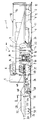
図1に示した軌框突固め兼安定化機械1は、前後部のレール走行台車2上に支持された機械フレーム3を有し、作業方向(矢印4)で見て後端部には、中央制御装置6を搭載した運転兼作業室5が配設されている。エネルギーユニット7は、種々の駆動装置並びに走行駆動装置8にエネルギーを供給するための機器である。レール9と枕木10とから成る軌框11の位置誤差を検出するために、第1の基準コード系12が設けられている。該第1の基準コード系は実質的に、機械長手方向に対して機械フレーム3の前端及び後端に配置されたフロント測定車輪13及びリア測定車輪13と、ミドル測定車輪14と、張設された弦コード15とから構成されている。
【0013】
後部のレール走行台車2の直ぐ前方に、2本の隣接した枕木10の下を同時に突固めるためのタンピングユニット16が設けられている。励振されるツールブレード17を有する該タンピングユニット16は昇降駆動装置18によって高さ調整可能に構成されている。突固めすべき枕木10の直下のバラストを締固めるためにツールブレード17は公知のように、スクイーズ駆動装置19によって機械長手方向に互いに対向掻き寄せ運動を行うことができる。ミドル測定車輪14の直ぐ前方には、軌框11に沿って転動可能な軌框レベリング−ライニングユニット20が配置されており、該軌框レベリング−ライニングユニットは高低・左右調整駆動装置21によって上下方向及び左右方向に調整可能に機械フレーム3と連結されている。軌框11を掴むために高低−左右調整可能な扛上ツール22が設けられている。
【0014】
軌框突固め兼安定化機械1の直ぐ後方に、レール走行台車24上に支持された車両フレーム25を有する安定化車両23が設けられている。該車両フレームは、フレーム前端部26でユニバーサルジョイント27によって軌框突固め兼安定化機械1の機械フレーム3と連結されている。ユニバーサルジョイント27とレール走行台車24との間のほぼ中央で、スタビライザユニット28が車両フレーム25と連結されている。鉛直方向の軌框位置誤差を検出するために第2の基準コード系29が設けられている。該第2の基準コード系は前記スタビライザユニット28の直ぐ後方で軌框に沿って転動可能かつ高低調整可能な測定車輪30を有している。機械長手方向に延在している弛みなく張設された弦コード31は、その前端部でもって第1基準コード系12のリア測定車輪13と、また後端部でもってレール走行台車24の車軸軸受ケーシング50上に支承されている。図2において追って詳説するスタビライザユニット28の駆動装置にはエネルギーユニット7によってエネルギーが供給される。安定化車両23の上限線32は、ユニバーサルジョイント27を通る鎖線で示した水平平面33内で位置決めされた車両フレーム25によって形成されている。これによって、運転兼作業室5内に位置している操作員は、作業方向とは逆向きの方向にも(配置転換時の移動走行時)問題なく軌框突固め兼安定化機械1を走行させることができる。
【0015】
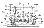
図2に示したように、スタビライザユニット28は(全部で4個の)フランジ付きローラ34によって軌框11のレール9上に載っている。機械横方向で互いに向き合っているそれぞれ2個のフランジ付きローラ34は、転動ガイド遊びを除くために、油圧式の拡開駆動装置35と連結されている。車両フレーム25に上端部を枢着されている駆動装置36と連結されているユニットケーシング37内には、偏心輪駆動装置として構成された2つのバイブレータ38が軸支されている。両バイブレータ38は、機械横方向にかつフランジ付きローラ34の回転軸線39に対して平行に経過する振動(矢印45で略示)を発生させるように構成されている。同一のレール9にそれぞれ2個ずつ配設されたフランジ付きローラ34間では、所謂ローラクランプ40が、機械長手方向に延びる軸線41を中心として旋回可能にユニットケーシング37に支承されている。該旋回は油圧駆動装置42によって行われる。各ローラクランプ40の下端部には、軸線43を中心として回転可能な皿形ローラ44が設けられている。駆動装置36の負荷下で軌框11に作用して最終的な目標位置へ該軌框を降下させる最大荷重圧が矢印46で表されている。前記最大荷重圧に対比して20〜100%の範囲内で軽減された荷重軽減値又は最小荷重圧は短い矢印47で略示されている。鉛直方向に軌框11に対して作用する荷重は約300kNまで無段調整可能であり、その場合、駆動装置36に作用する圧力は比例動作圧力弁を介して制御される。最大荷重圧とは、バラスト道床を締固めつつ横方向に振動させられる軌框を目標位置へ降下させるような力を意味している。このために選ばれる最大荷重圧の大きさは、例えば軌框降下高さ、作用時間、機械構造などのような種々のパラメータに関連している。
【0016】
異なった変化実施形態では、ユニバーサルジョイント27は水平平面内で機械長手方向にシフト可能に機械フレーム3に支承されていてもよい。このシフトは、図1に鎖線で略示した長手方向シフト駆動装置49によって行われる。これによって突固めシーケンス動作時間が特に異なっている場合でも安定化シーケンス動作時間はほぼ一定に保つことができる。
【0017】
図1に示した中央制御装置6は、タンピングユニット16の下降に並行して行われる、低い荷重軽減値から最大荷重圧へ荷重圧を上昇させるために、タンピングユニット16並びに、スタビライザユニット28に配設された昇降駆動装置18及び駆動装置36を同時にかつ自動的に負荷できるように構成されている。しかしながら、図9について追って説明するように、異なった実施形態では、個々の突固めシーケンス動作と安定化シーケンス動作とは、時間的に互いにずらされていてもよく、つまり異なった継続時間であってもよい。
【0018】
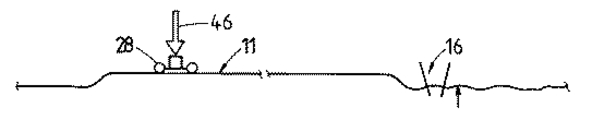
タンピングユニット16及びスタビライザユニット28並びに軌框11を略示した図3〜図6に基づいて本発明の軌框突固め・安定化法を次に説明する。タンピングユニット16の領域で軌框11は値xだけ暫定的な目標位置へ上昇され(図3の小さい方の矢印参照)、かつ正規の横方向位置へもたらされて、枕木下を突固められる。このために軌框突固め兼安定化機械の前進は中断される。突固め動作に並行してスタビライザユニット28による安定化動作によって、すでに枕木下を突固められた軌框11は、沈下設定値とも呼ばれる値yだけ最終的な目標位置へ管制下で降下される。このために(駆動装置36の負荷下で)矢印46で示した最大荷重圧がスタビライザユニット28に、ひいては軌框11にかけられる。測定車輪30と連結された高低測定フィーラ48(図1)は、所望の軌框降下を達成したことを記録し、次いで荷重軽減値又は最小荷重圧47を形成するように最大荷重圧46を自動的に低減する(図4)。前記荷重軽減値47は最大荷重圧46に対比して少なくとも20%低減されており、かつ軌框11に沿ってのスタビライザユニット28の確実な摩擦接続式ガイドを維持するために役立つ。この理想的な低減度合は、例えば最大荷重圧46の絶対量、安定化動作及び/又は荷重軽減動作の時間、振動周波数などのような種々のパラメータに関連している。
【0019】
突固め動作が終了すると即座にタンピングユニット16の上昇及びそれに直接続くタンピングユニット16及びスタビライザユニット28の共通の前進運動が、軌框突固め兼安定化機械1の前進に相応して行われる(図4)。この前進中にスタビライザユニット28は、荷重軽減動作と呼ばれるシーケンス動作区分においては、単に荷重軽減値47で負荷されるにすぎず、かつ、レール9に対する皿形ローラ44の圧着によって、依然としてレールと摩擦接続した状態を維持する。振動周波数は一定に維持されていてもよく、或いは選択的に低減されてもよい。
【0020】
次の突固め現場(図4に示したタンピングユニット16の破線位置参照)に到達すると、軌框突固め兼安定化機械1の前進は中断される。次いで突固め動作及び安定化動作を開始させるために、昇降駆動装置18と駆動装置36とを同時に負荷してタンピングユニット16の下降が行われると共に、スタビライザユニット28の荷重圧が最大荷重圧46に高められる(図5参照)。スタビライザユニット(28)の領域において軌框が所望の降下量に達しかつタンピングユニット16の領域における枕木下の突固めが終了すると(図6)、すでに述べたようにタンピングユニット16を上昇しかつ最大荷重圧46を低減しつつタンピングユニット16及びスタビライザユニット28を一緒に次の使用現場に前進させることによって新たな稼働サイクルが始まる。
【0021】
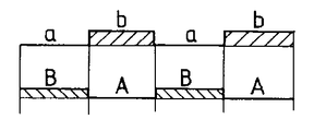
図7〜図9には、突固めシーケンス動作並びに安定化シーケンス動作のための本発明の方法の個々の処理態様が線図で図示されている。該線図では符号aで突固め動作が、また符号bでは前進が表されている。また符号A又は符号Bでは安定化シーケンス動作を形成する個々の安定化動作又は荷重軽減動作が示されている。符号tは時間軸、従って前記安定化シーケンス動作の個々の安定化動作時間及び個々の荷重軽減動作時間を表している。
【0022】
殊に図7の線図から判るように突固め動作a並びに、軌框の安定化を開始する安定化動作Aはその都度同時に開始される。突固め動作aに直接続く前進bに並行して、荷重軽減動作Bによってスタビライザユニット28に対する最大荷重圧の低減が行われる。従って個々のシーケンス動作並びにシーケンス動作区分は同期的に経過する。
【0023】
図8の線図から判るように、突固めシーケンス動作及び安定化シーケンス動作は半分ずつ互いにずらすこともできる。次いで突固め動作aに並行して荷重圧は荷重軽減値(荷重軽減動作B)に降下される。軌框降下(安定化動作A)は軌框突固め兼安定化機械1の前進bに並行して行われる。図7及び図8に示した実施態様では、最大荷重圧の大きさが安定化動作を延長するために例えば低減される限り、調和のために安定化動作時間は突固め動作時間に適合される。
【0024】
図9では、荷重圧を高めて開始される、安定化シーケンスの安定化動作Aの時間は、該安定化動作に並行してスタートした突固め動作aの時間よりも短い。すなわち荷重軽減動作Bはその一部(比較的僅かな部分)が突固め動作A中にすでに始まり、かつ次の突固め動作を開始するためにタンピングユニットが下降するまで続く。この場合は安定化動作Aが終了するとすでに長手方向シフト駆動装置49の負荷によって車両フレーム25の低速前進運動が開始される。
【0025】
図7〜図9に例示した突固め動作と安定化動作の3つの組合せ方式にすべて共通している点は、安定化シーケンス動作がそれぞれ軌框安定化を施工するための1つの安定化動作と、該安定化動作に直接続く荷重軽減動作とから成っていることである。
【図面の簡単な説明】
【図1】タンピングユニット及び安定化ユニットを装備した軌框突固め兼安定化機械の側面図である。
【図2】図1の断面線IIに沿った部分的な拡大横断面図である。
【図3】本発明の方法を実施する第1段階を示すタンピングユニット及びスタビライザユニットの概略図である。
【図4】本発明の方法を実施する第2段階を示すタンピングユニット及びスタビライザユニットの概略図である。
【図5】本発明の方法を実施する第3段階を示すタンピングユニット及びスタビライザユニットの概略図である。
【図6】本発明の方法を実施する第4段階を示すタンピングユニット及びスタビライザユニットの概略図である。
【図7】突固めシーケンス動作及び安定化シーケンス動作の第1施工態様を表す線図である。
【図8】突固めシーケンス動作及び安定化シーケンス動作の第2施工態様を表す線図である。
【図9】突固めシーケンス動作及び安定化シーケンス動作の第3施工態様を表す線図である。
【符号の説明】
1 軌框突固め兼安定化機械、 2 レール走行台車、 3 機械フレーム、 4 作業方向を示す矢印、 5 運転兼作業室、 6 中央制御装置、 7 エネルギーユニット、 8 走行駆動装置、 9 レール、10 枕木、 11 軌框、 12 第1の基準コード系、 13 フロント及びリア測定車輪、 14 ミドル測定車輪、 15 弦コード、16 タンピングユニット、 17 ツールブレード、 18 昇降駆動装置、 19 スクイーズ駆動装置、 20 軌框レベリング−ライニングユニット、 21 高低・左右調整駆動装置、 22 扛上ツール、 23 安定化車両、 24 レール走行台車、 25 車両フレーム、 26 フレーム前端部、 27 ユニバーサルジョイント、 28 スタビライザユニット、 29 第2の基準コード系、 30 測定車輪、 31弦コード、 32 上限線、 33 水平平面、 34 フランジ付きローラ、 35 拡開駆動装置、 36 駆動装置、 37 ユニットケーシング、 38 バイブレータ、 39 回転軸線、 40 ローラクランプ、 41 軸線、 42 油圧駆動装置、 43 軸線、 44皿形ローラ、 45 振動方向を示す矢印、 46 最大荷重圧を示す矢印、 47 荷重軽減値又は最小荷重圧を表す短い矢印、 48 高低測定フィーラ、 49 長手方向シフト駆動装置、 50 車軸軸受ケーシング、 x 値、 a 突固め動作、 b 前進、 A 安定化動作、 B 荷重軽減動作、 t 時間軸[0001]
BACKGROUND OF THE INVENTION
The present invention raises the track to a temporary target position and rams the sleepers in a step-by-step manner, while looking at the work direction and ramming the track behind the site with respect to the longitudinal direction of the track. The rail is loaded with vertical load pressure so that it will vibrate in the horizontal and vertical directions and form a rail descent value, and then lowered to the final target position. The present invention relates to a method for stabilizing the track.
[0002]
[Prior art]
In the method of the above type known from US Pat. No. 5,172,635, the rail position error correction operation obtained within the range of the under-cushion tamping, followed by the vertical direction This is combined with a three-dimensional compaction operation of the ballast roadbed by applying a horizontal load vibration and a horizontal rail vibration. In this known method, the required sleeper bearing seat is created, the non-uniformity caused by the action of the tool blade in the sleeper compartment is eliminated, the sleeper frontal head is compacted, and the track is intended. Is lowered to the target position. However, based on this operation, it is impossible to avoid the initial subsidence of the rail that cannot be avoided after the undercushion of the sleepers and the dynamic stress generated in the rail due to this initial subsidence.
[0003]
Intentional rail descent operation, also called rail stabilization, is performed during the continuous forward movement of the corresponding stabilizer unit, with a constant load pressure to obtain a constant rail descent value. . In parallel with the rail stabilization process, the track tamping is performed inside the common mechanical unit immediately in front of the track stabilization as viewed in the work direction, but the track ramming continuously moves forward. It is constructed in each sleeper area in a step-by-step manner (incremental) while moving the tamping unit relative to the mechanical unit.
[0004]
Another mechanical unit that is step-by-step advanced at the work site for constructing a rail stabilization process combined with a tamping action under a sleeper is disclosed in U.S. Pat. No. 4,046,079, U.S. Pat. Known from US Pat. No. 4,460,078, British Patent No. 2094379 and US Pat. No. 4,430,946.
[0005]
[Problems to be solved by the invention]
By the way, the problem of the present invention is to improve the method of the type mentioned at the beginning by step-by-step advancement so that a satisfactory work result can be obtained with relatively little labor and mechanical costs. It is the combination of the under sleeper tamping achieved and the three-dimensional compaction of the ballast roadbed to avoid the initial settling of the track.
[0006]
[Means for Solving the Problems]
In order to solve the above-mentioned problems, the constituent means of the present invention comprises a stabilizing operation and a load reducing operation that are continuously repeated in parallel with a tamping sequence operation comprising a continuously repeating tamping operation and a forward movement. Each of the rails is lowered step by step to the final target position during another stabilization sequence operation consisting of and the load pressure is increased to the rail drop value during the stabilization operation, and the subsequent load This is to reduce the load pressure to the load reduction value during the reduction operation.
[0007]
[Action]
It is well-known in the railway technology field, and is included in the journal “RailwayTrack & Structures”, published in March 1984, pages 48-52 (especially
[0008]
As can be seen from the patent documents listed in the third paragraph of the section [Prior Art], the track stabilization process is mechanically combined with a multiple tie tamper that advances step by step at the work site. There has been a desire for many years to simplify the structure and reduce labor costs. However, all such known proposals have not yet been put into practical use.
[0009]
By the way, according to the processing operation according to the present invention, the step-by-step tamping operation is first combined with a stabilization processing operation which is also performed step-by-step in parallel with the tamping operation. The In this way, during the stabilization sequence operation, two different load pressures (railing drop value and load reduction value) are generated alternately, which is completely different from the operation method performed in the past. An optimal adaptation of the stabilization operation to the tamping operation performed step by step is ensured. Thus, in particular, it is possible to completely eliminate the different stabilizing effects on the rail and thus the different lowering of the rail due to the alternating machine advance. In spite of the fact that a certain degree of efficiency loss has to be accepted in comparison with the known continuous working system, the method according to the invention in particular simplifies the correction of the position of relatively short rail segments. At the same time, mechanical and labor costs will be greatly reduced.
[0010]
Advantageous configurations of the present invention are apparent from the means described in
[0011]
DETAILED DESCRIPTION OF THE INVENTION
Next, embodiments of the present invention will be described in detail with reference to the drawings.
[0012]
1 has a
[0013]
A
[0014]
A stabilizing
[0015]
As shown in FIG. 2, the
[0016]
In a different variant embodiment, the universal joint 27 may be mounted on the
[0017]
The
[0018]
The rail tamping / stabilizing method of the present invention will be described below with reference to FIGS. 3 to 6 schematically showing the tamping
[0019]
Immediately after the tamping operation is completed, the tamping
[0020]
When the next tamping site (see the position of the tamping
[0021]
7-9 illustrate in diagram form the individual processing aspects of the method of the present invention for the compaction sequence operation as well as the stabilization sequence operation. In the diagram, a compaction operation is represented by symbol a, and a forward motion is represented by symbol b. Reference numeral A or B indicates individual stabilization operations or load reduction operations that form the stabilization sequence operation. The symbol t represents the time axis, and thus the individual stabilization operation time and the individual load reduction operation time of the stabilization sequence operation.
[0022]
In particular, as can be seen from the diagram of FIG. 7, the tamping operation a and the stabilization operation A for starting the stabilization of the rail are started simultaneously each time. In parallel with the advance b that directly follows the tamping operation a, the load reducing operation B reduces the maximum load pressure on the
[0023]
As can be seen from the diagram of FIG. 8, the tamping sequence operation and the stabilization sequence operation can also be offset from each other by half. Next, in parallel with the tamping operation a, the load pressure is lowered to a load reduction value (load reduction operation B). The rail descent (stabilization operation A) is performed in parallel with the forward movement b of the rail tamping and stabilizing
[0024]
In FIG. 9, the time of the stabilization operation A in the stabilization sequence that is started by increasing the load pressure is shorter than the time of the tamping operation a that starts in parallel with the stabilization operation. That is, part (relatively small part) of the load reducing operation B has already started during the tamping operation A and continues until the tamping unit is lowered to start the next tamping operation. In this case, when the stabilizing operation A is completed, the
[0025]
The points that are common to the three combination methods of the tamping operation and the stabilization operation illustrated in FIGS. 7 to 9 are that the stabilization sequence operation is one stabilization operation for constructing the rail stabilization. The load reducing operation directly follows the stabilizing operation.
[Brief description of the drawings]
FIG. 1 is a side view of a rail tamping and stabilizing machine equipped with a tamping unit and a stabilizing unit.
FIG. 2 is a partial enlarged cross-sectional view along section line II of FIG.
FIG. 3 is a schematic view of a tamping unit and a stabilizer unit showing a first stage of carrying out the method of the present invention.
FIG. 4 is a schematic view of a tamping unit and a stabilizer unit showing a second stage of carrying out the method of the present invention.
FIG. 5 is a schematic view of a tamping unit and a stabilizer unit showing a third stage for carrying out the method of the present invention.
FIG. 6 is a schematic view of a tamping unit and a stabilizer unit showing a fourth stage for carrying out the method of the present invention.
FIG. 7 is a diagram showing a first construction mode of a tamping sequence operation and a stabilization sequence operation.
FIG. 8 is a diagram showing a second construction mode of the tamping sequence operation and the stabilization sequence operation.
FIG. 9 is a diagram showing a third construction mode of the tamping sequence operation and the stabilization sequence operation.
[Explanation of symbols]
DESCRIPTION OF SYMBOLS 1 Rail tamping and stabilization machine, 2 Rail traveling trolley, 3 Machine frame, 4 Arrow which shows working direction, 5 Driving / working room, 6 Central controller, 7 Energy unit, 8 Traveling drive, 9 Rail, 10 Sleepers, 11 rails, 12 first reference code system, 13 front and rear measuring wheels, 14 middle measuring wheels, 15 string cords, 16 tamping units, 17 tool blades, 18 lifting drive device, 19 squeeze drive device, 20 track框 Leveling-Lining unit, 21 Height / Left / Right adjustment drive device, 22 扛 Upper tool, 23 Stabilized vehicle, 24 Rail traveling cart, 25 Vehicle frame, 26 Frame front end, 27 Universal joint, 28 Stabilizer unit, 29 Reference code system, 30 measuring wheels, 31 string cord, 32 on Wire, 33 horizontal plane, 34 roller with flange, 35 expansion drive device, 36 drive device, 37 unit casing, 38 vibrator, 39 rotation axis, 40 roller clamp, 41 axis, 42 hydraulic drive device, 43 axis, 44 dish type 45, arrow indicating vibration direction, 46 arrow indicating maximum load pressure, 47 short arrow indicating load reduction value or minimum load pressure, 48 height measuring feeler, 49 longitudinal shift drive device, 50 axle bearing casing, x value, a tamping operation, b advance, A stabilization operation, B load reduction operation, t time axis
Claims (4)
Applications Claiming Priority (2)
| Application Number | Priority Date | Filing Date | Title |
|---|---|---|---|
| AT24495 | 1995-02-09 | ||
| AT244/95 | 1995-05-02 |
Publications (2)
| Publication Number | Publication Date |
|---|---|
| JPH08239801A JPH08239801A (en) | 1996-09-17 |
| JP3746097B2 true JP3746097B2 (en) | 2006-02-15 |
Family
ID=3485386
Family Applications (1)
| Application Number | Title | Priority Date | Filing Date |
|---|---|---|---|
| JP02025596A Expired - Fee Related JP3746097B2 (en) | 1995-02-09 | 1996-02-06 | How to stabilize the track by tamping under the sleepers |
Country Status (15)
| Country | Link |
|---|---|
| US (1) | US5640909A (en) |
| EP (1) | EP0726360B1 (en) |
| JP (1) | JP3746097B2 (en) |
| CN (1) | CN1087048C (en) |
| AT (1) | ATE176936T1 (en) |
| AU (1) | AU699770B2 (en) |
| CA (1) | CA2169138C (en) |
| CZ (1) | CZ285325B6 (en) |
| DE (1) | DE59601320D1 (en) |
| DK (1) | DK0726360T3 (en) |
| ES (1) | ES2130776T3 (en) |
| FI (1) | FI118815B (en) |
| PL (1) | PL180629B1 (en) |
| RU (1) | RU2143512C1 (en) |
| SK (1) | SK283239B6 (en) |
Families Citing this family (19)
| Publication number | Priority date | Publication date | Assignee | Title |
|---|---|---|---|---|
| AT500949B8 (en) * | 2004-10-01 | 2007-02-15 | Plasser Bahnbaumasch Franz | MACHINE FOR IMPLEMENTING A RAILWAY CORRECTION |
| AT503437B1 (en) * | 2006-08-10 | 2007-10-15 | Plasser Bahnbaumasch Franz | Method for ballasting and stabilization of track, involves reducing transverse vibrations producing dynamic impact force by repetitive ballasting of track section |
| KR100838227B1 (en) * | 2007-04-16 | 2008-06-16 | 한국철도기술연구원 | Structure of high-strength and rapidly-hardening prepacked concrete track for carrying out mechanization and working method thereof |
| AT505909B1 (en) * | 2007-11-27 | 2009-05-15 | Plasser Bahnbaumasch Franz | METHOD AND MACHINE FOR COMPACING SCOTTER OF A JOINT |
| CN102486018A (en) * | 2010-12-03 | 2012-06-06 | 襄樊金鹰轨道车辆有限责任公司 | Track stabilizing device |
| CN102486017A (en) * | 2010-12-03 | 2012-06-06 | 襄樊金鹰轨道车辆有限责任公司 | Rail stabilization device |
| CN102720101B (en) * | 2012-05-22 | 2015-07-08 | 昆明中铁大型养路机械集团有限公司 | Line tamping stabilizing car and turnout stabilizing method |
| RU2547108C1 (en) * | 2013-12-11 | 2015-04-10 | Анатолий Николаевич Шилкин | Method for correction of rail track position |
| PL2902546T3 (en) * | 2014-01-30 | 2018-03-30 | Hp3 Real Gmbh | Device for the compaction of railway ballast |
| JP6584493B2 (en) * | 2014-08-13 | 2019-10-02 | プラッサー ウント トイラー エクスポート フォン バーンバウマシーネン ゲゼルシャフト ミット ベシュレンクテル ハフツングPlasser & Theurer, Export von Bahnbaumaschinen, Gesellschaft m.b.H. | Device for stabilizing the orbit |
| AT518023B1 (en) * | 2015-12-02 | 2018-04-15 | Plasser & Theurer Export Von Bahnbaumaschinen Gmbh | Tamping machine and method for performing a position correction of a track |
| CN108086067B (en) * | 2016-11-23 | 2023-10-17 | 中国铁建高新装备股份有限公司 | Continuous type circuit switch stabilization car |
| WO2018189914A1 (en) * | 2017-04-14 | 2018-10-18 | 富士通株式会社 | Tactile sensation presentation device and simulation system |
| CN110130167A (en) * | 2018-02-08 | 2019-08-16 | 中国铁建高新装备股份有限公司 | A kind of railroad track geometric parameter measurement device and play track lining control method |
| JP7157965B2 (en) * | 2018-06-05 | 2022-10-21 | 株式会社高萩自工 | track maintenance vehicle |
| US11155135B2 (en) | 2018-06-06 | 2021-10-26 | Nordco Inc. | Traction system for railcar movers |
| AT523228A1 (en) * | 2019-12-10 | 2021-06-15 | Plasser & Theurer Export Von Bahnbaumaschinen Gmbh | Machine and method for stabilizing a ballast track |
| CN112064431B (en) * | 2020-09-11 | 2022-08-16 | 李卫 | Tamping tool for track traffic |
| CN113202079B (en) * | 2021-04-30 | 2022-08-23 | 潍坊峡山水务有限公司 | Dam slope tamping device and using method thereof |
Family Cites Families (10)
| Publication number | Priority date | Publication date | Assignee | Title |
|---|---|---|---|---|
| AT343165B (en) * | 1975-01-31 | 1978-05-10 | Plasser Bahnbaumasch Franz | MOBILE BOTTOM BED COMPACTION MACHINE FOR CORRECTING THE TRACK |
| US4046078A (en) * | 1975-01-31 | 1977-09-06 | Franz Plasser Bahnbaumaschinen-Industriegesellschaft M.B.H. | Track surfacing apparatus |
| US4125075A (en) * | 1977-03-18 | 1978-11-14 | Canron, Inc. | High speed production tamper compactor |
| AT371170B (en) * | 1981-01-16 | 1983-06-10 | Plasser Bahnbaumasch Franz | TRACKABLE MACHINE FOR COMPACTION, ESPECIALLY TRACK LEVELING PLUG MACHINE, WITH STABILIZATION UNIT |
| AT371171B (en) * | 1981-01-28 | 1983-06-10 | Plasser Bahnbaumasch Franz | TRACK LEVELING PLUG AND LEVELING MACHINE WITH STABILIZATION UNIT |
| US4643101A (en) * | 1982-11-23 | 1987-02-17 | Franz Plasser Bahnbaumaschinen-Industriegesellschaft M.B.H. | Mobile track leveling, lining and tamping machine |
| AT389132B (en) * | 1987-09-04 | 1989-10-25 | Plasser Bahnbaumasch Franz | CONTINUOUSLY (NON-STOP) TRAVELABLE TRACKING MACHINE |
| AT400162B (en) * | 1990-02-06 | 1995-10-25 | Plasser Bahnbaumasch Franz | METHOD AND TRACKING MACHINE FOR MEASURING THE CROSS SHIFTING RESISTANCE |
| AT402952B (en) * | 1991-03-26 | 1997-10-27 | Plasser Bahnbaumasch Franz | TRACK CONSTRUCTION MACHINE FOR CONTROLLED LOWERING OF A TRACK |
| AT401943B (en) * | 1992-08-21 | 1996-12-27 | Plasser Bahnbaumasch Franz | CONTINUOUSLY MOVABLE TRACKING MACHINE |
-
1996
- 1996-01-05 ES ES96890002T patent/ES2130776T3/en not_active Expired - Lifetime
- 1996-01-05 EP EP96890002A patent/EP0726360B1/en not_active Expired - Lifetime
- 1996-01-05 DE DE59601320T patent/DE59601320D1/en not_active Expired - Lifetime
- 1996-01-05 AT AT96890002T patent/ATE176936T1/en active
- 1996-01-05 DK DK96890002T patent/DK0726360T3/en active
- 1996-01-23 CZ CZ96208A patent/CZ285325B6/en not_active IP Right Cessation
- 1996-01-24 RU RU96101172A patent/RU2143512C1/en not_active IP Right Cessation
- 1996-02-05 PL PL96312669A patent/PL180629B1/en not_active IP Right Cessation
- 1996-02-06 JP JP02025596A patent/JP3746097B2/en not_active Expired - Fee Related
- 1996-02-08 SK SK173-96A patent/SK283239B6/en unknown
- 1996-02-08 AU AU44421/96A patent/AU699770B2/en not_active Ceased
- 1996-02-08 FI FI960580A patent/FI118815B/en not_active IP Right Cessation
- 1996-02-08 CA CA002169138A patent/CA2169138C/en not_active Expired - Fee Related
- 1996-02-08 CN CN96104004.1A patent/CN1087048C/en not_active Expired - Fee Related
- 1996-02-09 US US08/599,327 patent/US5640909A/en not_active Expired - Lifetime
Also Published As
| Publication number | Publication date |
|---|---|
| RU2143512C1 (en) | 1999-12-27 |
| SK17396A3 (en) | 1997-03-05 |
| CA2169138C (en) | 2005-12-20 |
| CA2169138A1 (en) | 1996-08-10 |
| ES2130776T3 (en) | 1999-07-01 |
| CZ285325B6 (en) | 1999-07-14 |
| PL180629B1 (en) | 2001-03-30 |
| JPH08239801A (en) | 1996-09-17 |
| FI960580A0 (en) | 1996-02-08 |
| AU699770B2 (en) | 1998-12-17 |
| EP0726360A1 (en) | 1996-08-14 |
| ATE176936T1 (en) | 1999-03-15 |
| DE59601320D1 (en) | 1999-04-01 |
| FI118815B (en) | 2008-03-31 |
| CZ20896A3 (en) | 1996-08-14 |
| CN1135002A (en) | 1996-11-06 |
| EP0726360B1 (en) | 1999-02-24 |
| DK0726360T3 (en) | 1999-09-27 |
| US5640909A (en) | 1997-06-24 |
| PL312669A1 (en) | 1996-08-19 |
| FI960580A (en) | 1996-08-10 |
| CN1087048C (en) | 2002-07-03 |
| AU4442196A (en) | 1996-08-15 |
| SK283239B6 (en) | 2003-04-01 |
Similar Documents
| Publication | Publication Date | Title |
|---|---|---|
| JP3746097B2 (en) | How to stabilize the track by tamping under the sleepers | |
| US4064807A (en) | Mobile apparatus for non-stop track leveling and ballast tamping | |
| US4046078A (en) | Track surfacing apparatus | |
| CA1039112A (en) | Track surfacing apparatus | |
| RU2048630C1 (en) | Method and tie tamper for compacting railway track rubble | |
| CA1039113A (en) | Track surfacing apparatus | |
| JP2860200B2 (en) | Rail maintenance machine | |
| GB2094378A (en) | A track tamping and levelling machine with a tamping unit | |
| US4125075A (en) | High speed production tamper compactor | |
| EP2661524B1 (en) | Vertical force stabilizer | |
| JPH1046507A (en) | Roadbed compactor | |
| JP3834116B2 (en) | Roadbed compaction machine | |
| US20220025585A1 (en) | Method and track maintenance machine for treatment of a ballast track | |
| FI79581C (en) | KOERBAR SPAORSTAMPNINGS-PLANINGS- OCH RIKTMASKIN. | |
| JP4824203B2 (en) | Method and machine for tamping track | |
| JP3921254B2 (en) | Method and tamping machine for tamping under railroad sleepers | |
| JP3107898U (en) | Tamping machine for tamping track | |
| CA1192444A (en) | Mobile ballast compacting machine | |
| JPH035503A (en) | Continuously advancing type track compacting equipment including plowing apparatus | |
| JP2004116284A (en) | Machine and method for tamping sleeper of track | |
| JPS5922001B2 (en) | A movable track repair machine that is equipped with a device for hardening ballast under track sleepers and a ballast removal device for ballast in the central part under the sleepers. | |
| JPH08246404A (en) | Compacting method under large number of sleeper of track skeleton | |
| RU2044811C1 (en) | Smoothing/driving under machine | |
| JPH03183801A (en) | Ballast compactor for track maintenance |
Legal Events
| Date | Code | Title | Description |
|---|---|---|---|
| TRDD | Decision of grant or rejection written | ||
| A01 | Written decision to grant a patent or to grant a registration (utility model) |
Free format text: JAPANESE INTERMEDIATE CODE: A01 Effective date: 20051021 |
|
| A61 | First payment of annual fees (during grant procedure) |
Free format text: JAPANESE INTERMEDIATE CODE: A61 Effective date: 20051121 |
|
| R150 | Certificate of patent or registration of utility model |
Free format text: JAPANESE INTERMEDIATE CODE: R150 |
|
| FPAY | Renewal fee payment (event date is renewal date of database) |
Free format text: PAYMENT UNTIL: 20081202 Year of fee payment: 3 |
|
| FPAY | Renewal fee payment (event date is renewal date of database) |
Free format text: PAYMENT UNTIL: 20091202 Year of fee payment: 4 |
|
| FPAY | Renewal fee payment (event date is renewal date of database) |
Free format text: PAYMENT UNTIL: 20101202 Year of fee payment: 5 |
|
| FPAY | Renewal fee payment (event date is renewal date of database) |
Free format text: PAYMENT UNTIL: 20101202 Year of fee payment: 5 |
|
| FPAY | Renewal fee payment (event date is renewal date of database) |
Free format text: PAYMENT UNTIL: 20111202 Year of fee payment: 6 |
|
| FPAY | Renewal fee payment (event date is renewal date of database) |
Free format text: PAYMENT UNTIL: 20111202 Year of fee payment: 6 |
|
| FPAY | Renewal fee payment (event date is renewal date of database) |
Free format text: PAYMENT UNTIL: 20121202 Year of fee payment: 7 |
|
| FPAY | Renewal fee payment (event date is renewal date of database) |
Free format text: PAYMENT UNTIL: 20121202 Year of fee payment: 7 |
|
| FPAY | Renewal fee payment (event date is renewal date of database) |
Free format text: PAYMENT UNTIL: 20131202 Year of fee payment: 8 |
|
| R250 | Receipt of annual fees |
Free format text: JAPANESE INTERMEDIATE CODE: R250 |
|
| LAPS | Cancellation because of no payment of annual fees |