EP0726360A1 - Method and machine for tamping and stabilizing a railway track - Google Patents
Method and machine for tamping and stabilizing a railway track Download PDFInfo
- Publication number
- EP0726360A1 EP0726360A1 EP96890002A EP96890002A EP0726360A1 EP 0726360 A1 EP0726360 A1 EP 0726360A1 EP 96890002 A EP96890002 A EP 96890002A EP 96890002 A EP96890002 A EP 96890002A EP 0726360 A1 EP0726360 A1 EP 0726360A1
- Authority
- EP
- European Patent Office
- Prior art keywords
- track
- tamping
- unit
- stabilizing
- machine
- Prior art date
- Legal status (The legal status is an assumption and is not a legal conclusion. Google has not performed a legal analysis and makes no representation as to the accuracy of the status listed.)
- Granted
Links
Images
Classifications
-
- E—FIXED CONSTRUCTIONS
- E01—CONSTRUCTION OF ROADS, RAILWAYS, OR BRIDGES
- E01B—PERMANENT WAY; PERMANENT-WAY TOOLS; MACHINES FOR MAKING RAILWAYS OF ALL KINDS
- E01B27/00—Placing, renewing, working, cleaning, or taking-up the ballast, with or without concurrent work on the track; Devices therefor; Packing sleepers
- E01B27/12—Packing sleepers, with or without concurrent work on the track; Compacting track-carrying ballast
- E01B27/13—Packing sleepers, with or without concurrent work on the track
- E01B27/16—Sleeper-tamping machines
- E01B27/17—Sleeper-tamping machines combined with means for lifting, levelling or slewing the track
Definitions
- the invention relates to a method for tamping and stabilizing a track, the track being raised to a provisional target position and gradually being supported, while in the working direction behind it the track is displaced in horizontal and perpendicular to the longitudinal direction of the track and with a vertical value to form a lowering value Load and thus lowered to a final target position as well as a machine for performing the method.
- Such a method combines the correction of the track position errors that can be achieved in the context of a tamping with a subsequent spatial compaction of the ballast bedding by applying a vertical load and horizontal track vibrations.
- the necessary sleeper supports are produced, the inhomogeneity caused by the intervention of tamping picks in the intermediate compartment is eliminated, the front head is compacted and the track is lowered into the desired position. As a result, the inevitable initial settlement of a track and the resulting dynamic forces can be avoided.
- the targeted track lowering referred to as track stabilization is carried out with the continuous forward movement of a corresponding stabilization unit, the load remaining constant in order to achieve a constant lowering value for the track.
- the object of the present invention is to create a method of the generic type with which, with relatively little effort in terms of personnel and machinery, a satisfactory combination of a tamping that can be achieved by gradual right of way with a spatial compression of the ballast bed to avoid initial settling of the track can be achieved .
- the step-by-step tamping process is now combined for the first time with a stabilization process which also takes place step-by-step in parallel. It is only through this alternating application of two different loads (lowering and relief value) during the stabilization sequence that is completely different from the previously practiced procedure that the stabilization process can be optimally coordinated with the tamping process that takes place immediately before. In particular, a different stabilizing effect on the track caused by the alternating machine approach and thus its different lowering can be excluded. Although a reduction in performance is to be accepted in comparison with the known continuous mode of operation, the method according to the invention is particularly suitable for simplified position correction of shorter track sections with reduced mechanical and personnel expenditure.
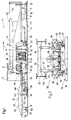
- a track tamping and stabilizing machine 1 shown in FIG. 1 has a machine frame 3 supported on rail running gear 2, to which a driving and working cabin 5 with a central control device 6 is assigned at the rear end with respect to the working direction (arrow 4).
- An energy unit 7 is used to supply the various drives and a travel drive 8.
- a first reference system 12 is provided to determine position errors of a track 11 formed from rails 9 and sleepers 10. This is composed essentially of two measuring carriages 13 arranged at the end on the machine frame 3 with respect to the longitudinal direction of the machine, a middle measuring carriage 14 and tensioned chords 15.
- a tamping unit 16 is provided for simultaneously tamping two adjacent sleepers 10.
- This tamping unit 16, which has a vibrating tamping pick 17, is designed to be height-adjustable by drives 18.
- the tamping pick 17 can be provided in a known manner to one another in the longitudinal direction of the machine by means of auxiliary drives 19.
- a track lifting / straightening unit 20 which can be rolled off the track 11 and which is connected to the machine frame 3 by drives 21 which can be adjusted in height and on the side. Height and side adjustable lifting tools 22 are provided for gripping the track 11.
- a stabilizer vehicle 23 with a vehicle frame 25 supported on a rail chassis 24. This is with a front frame end 26 through a universal joint 27 with the machine frame 3 of the track tamping and stabilizing machine 1 connected.
- a stabilizing unit 28 is connected to the vehicle frame 25 approximately midway between the joint 27 and the rail running gear 24.
- a second reference system 29 is provided to determine the vertical track position errors.
- This has a measuring carriage 30 which can be rolled off and is height-adjustable directly behind the stabilizing unit 28 on the track.
- a taut tendon 31 running in the longitudinal direction of the machine is mounted with its front end on the rear measuring carriage 13 of the first reference system 12 and with the rear end on an axle bearing housing 50 of the rail carriage 24.
- the drives of the stabilization unit 28, which are described in more detail in FIG. 2, are supplied with energy by the energy unit 7.
- An upper boundary line 32 of the stabilizer vehicle 23 is formed by the vehicle frame 25 positioned in a horizontal plane 33 leading through the joint 27 and indicated by a dash-dotted line. This ensures that an operator in the driving and working cabin 5 can easily move the track tamping and stabilizing machine 1 in the direction opposite to the working direction (for a transfer run).
- the stabilization unit 28 rests on the rails 9 of the track 11 by means of (four in total) flange rollers 34.
- two flanged rollers 34 lying opposite one another in the cross-machine direction are connected to a hydraulic spreading drive 35 in order to switch off the backlash.
- a unit housing 37 connected to drives 36, the upper ends of which are articulated on the vehicle frame 25, two vibrators 38 designed as eccentric drives are mounted. These are designed to generate vibrations (indicated by arrow 45) that run in the cross machine direction and parallel to the rotation axes 39 of the flanged rollers 34.
- roller tongs 40 are mounted on the unit housing 37 so as to be pivotable about an axis 41 running in the machine longitudinal direction. This pivoting takes place by means of a hydraulic drive 42.
- a roller table 44 rotatable about an axis 43 is provided.
- an arrow 46 is the maximum load acting upon the drives 36 and acting on the track 11 and lowering it into the final desired position is shown.
- the shorter arrow 47 indicates a relief value or minimum loading pressure that is reduced in a range of 20 to 100 percent compared to the maximum load.
- the load acting on the track 11 in the vertical direction is infinitely adjustable up to approximately 300 kilonewtons by controlling the pressure acting on the drives 36 via a proportional pressure valve.
- Maximum load is to be understood as the force with which the track vibrated in transverse vibrations is lowered into the desired position while compacting the ballast bed.
- the size of the maximum load chosen for this depends on various parameters, such as the height of the track lowering, duration of exposure, type of machine, etc.
- the joint 27 can also be mounted on the machine frame 3 so as to be displaceable in the plane 33 and in the longitudinal direction of the machine.
- the displacement takes place by means of a longitudinal displacement drive 49 (indicated by dash-dotted lines in FIG. 1).
- a longitudinal displacement drive 49 indicated by dash-dotted lines in FIG. 1.
- the central control device 6 shown in FIG. 1 is designed for automatic and simultaneous actuation of the drives 18, 36 assigned to the tamping unit 16 and the stabilization unit 28 for an increase in the load from a low relief value to the maximum load parallel to the lowering of the tamping unit 16.
- the individual tamping and stabilizing sequences can, however, also be shifted in time from one another, i.e. take different lengths.
- the method according to the invention is described in more detail below.
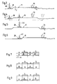
- the track 11 is raised by the value x to a provisional target position (see small arrow in FIG. 3), brought into the correct lateral position and supports.
- the right of way is interrupted.
- the stabilizing unit 28 is used in a stabilizing process to lower the track 11, already tamped, by the value y, also referred to as setting value, into the final desired position.
- a maximum load, designated 46 is applied to the stabilization unit 28 and thus to the track 11 (under the action of the drives 36).
- a height sensor 48 connected to the measuring carriage 30 registers the achievement of the desired lowering of the track and then automatically reduces the maximum load 46 to form a relief value 47 or minimum load pressure (FIG. 4). This is reduced by at least 20 percent compared to the maximum load 46 and serves to maintain a safe, force-fitting guidance of the stabilization unit 28 on the track 11.
- the ideal extent of the reduction is dependent on various parameters, such as the absolute size of the maximum load 46, duration of the stabilization. and / or relief process, oscillation frequency, etc. dependent.
- the tamping unit 16 is raised and the immediate subsequent joint forward movement of the tamping and stabilizing unit 16, 28 takes place with the corresponding advance of the machine 1 (FIG. 4).
- the stabilization unit 28 is only subjected to the relief value 47 in a sequence section referred to as a relief operation and continues to remain non-positively engaged by pressing the roller table 44 against the rails 9.
- the oscillation frequency can be kept unchanged or optionally reduced.
- the machine approach is interrupted.
- the tamping unit 16 is lowered and the load on the stabilizing unit 28 is increased to the maximum value 46 (see FIG. 5).
- the desired lowering of the track in the area of the stabilizing unit 28 FIG. 6
- the completion of the tamping in the area of the tamping unit 16 begins a new cycle in the manner already described in that both units 16, 28 are jointly moved forward to the next place of use while lifting the tamping unit 16 and reducing the maximum load 46.
- FIG. 7 shows above all that the tamping process a on the one hand and the stabilization process A initiating the track stabilization on the other hand are initiated simultaneously.
- the relief process B reduces the maximum load on the stabilization unit. This means that both the individual sequences and the sequence sections run synchronously.
- the stuffing and stabilizing sequences can also be shifted by half a sequence to one another. Thereafter, the load is reduced to the relief value (relief procedure B) in parallel with the tamping procedure a.
- the lowering of the track (stabilization process A) takes place parallel to the approach of machine 1.
- the duration of the stabilization process can be adapted to match the duration of the tamping process, as the size of the maximum load to extend the stabilization process, for example is reduced.
- the stabilization process A of the stabilization sequence initiated with the increase in the load takes less time than the tamping process a started in parallel.
- the relief process B begins to a (lesser) extent already during the tamping process and until it is lowered of the tamping unit to initiate the next tamping process.
- a slow forward movement of the vehicle frame 25 can be initiated by acting on the longitudinal displacement drive 49 after the stabilization process A has ended.
- the stabilizing sequence is composed in each case of a stabilizing process for carrying out the track stabilization and an immediately following unloading process.
Abstract
Description
Die Erfindung betrifft ein Verfahren zum Unterstopfen und Stabilisieren eines Gleises, wobei das Gleis in eine vorläufige Soll-Lage angehoben und schrittweise unterstopft wird, während in Arbeitsrichtung dahinter das Gleis in horizontal und senkrecht zur Gleislängsrichtung verlaufende Schwingungen versetzt sowie unter Bildung eines Absenkwertes mit einer vertikalen Auflast belastet und damit in eine endgültige Soll-Lage abgesenkt wird sowie eine Maschine zur Durchführung des Verfahrens.The invention relates to a method for tamping and stabilizing a track, the track being raised to a provisional target position and gradually being supported, while in the working direction behind it the track is displaced in horizontal and perpendicular to the longitudinal direction of the track and with a vertical value to form a lowering value Load and thus lowered to a final target position as well as a machine for performing the method.
Ein derartiges, durch die US 5 172 635 bekanntes Verfahren kombiniert die im Rahmen einer Unterstopfung erzielbare Berichtigung der Gleislagefehler mit einer anschließenden räumlichen Verdichtung der Schotterbettung durch Aufbringung einer vertikalen Auflast sowie horizontaler Gleisschwingungen. Bei diesem Verfahren werden die erforderlichen Schwellenauflager hergestellt, die durch den Eingriff von Stopfpickeln im Zwischenfach verursachte Inhomogenität beseitigt, der Vorkopf verdichtet und das Gleis gezielt in die Soll-Lage abgesenkt. Dadurch sind die nach der Unterstopfung unvermeidlichen Anfangssetzungen eines Gleises und daraus entstehende dynamische Kräfte vermeidbar.Such a method, known from US Pat. No. 5,172,635, combines the correction of the track position errors that can be achieved in the context of a tamping with a subsequent spatial compaction of the ballast bedding by applying a vertical load and horizontal track vibrations. With this method, the necessary sleeper supports are produced, the inhomogeneity caused by the intervention of tamping picks in the intermediate compartment is eliminated, the front head is compacted and the track is lowered into the desired position. As a result, the inevitable initial settlement of a track and the resulting dynamic forces can be avoided.
Die als Gleisstabilisation bezeichnete gezielte Gleisabsenkung wird unter kontinuierlicher Vorwärtsbewegung eines entsprechenden Stabilisationsaggregates durchgeführt, wobei die Auflast zur Erzielung eines konstanten Absenkwertes für das Gleis konstant bleibt. Parallel zur Gleisstabilisation erfolgt in Arbeitsrichtung unmittelbar davor innerhalb einer gemeinsamen Maschineneinheit die Gleisunterstopfung, die - unter Relativverschiebung eines Stopfaggregates in bezug auf die kontinuierlich vorwärtsbewegte Maschineneinheit - schrittweise im Bereich jeder Schwelle durchgeführt wird.The targeted track lowering referred to as track stabilization is carried out with the continuous forward movement of a corresponding stabilization unit, the load remaining constant in order to achieve a constant lowering value for the track. Parallel to the track stabilization in the working direction, immediately before this, the track is tamped within a common machine unit, which - with relative displacement of a tamping unit with respect to the continuously moving machine unit - is carried out step by step in the area of each threshold.
Weitere, im Arbeitseinsatz schrittweise vorfahrende Maschineneinheiten zur Durchführung einer mit einer Unterstopfung kombinierten Stabilisation eines Gleises sind durch folgende Patentschriften bekannt: US 4 046 079, US 4 046 078, GB 2 094 379, US 4 430 946.Further machine units which advance step-by-step during work to carry out a stabilization of a track combined with tamping are known from the following patents: US 4,046,079, US 4,046,078, GB 2,094,379, US 4,430,946.
Die Aufgabe der vorliegenden Erfindung liegt nun in der Schaffung eines Verfahrens der gattungsgemäßen Art, mit dem unter relativ geringem personellen und maschinellen Aufwand eine im Arbeitsergebnis zufriedenstellende Kombination einer durch schrittweise Vorfahrt erreichbaren Unterstopfung mit einer räumlichen Verdichtung der Schotterbettung zur Vermeidung von Anfangssetzungen des Gleises erzielbar ist.The object of the present invention is to create a method of the generic type with which, with relatively little effort in terms of personnel and machinery, a satisfactory combination of a tamping that can be achieved by gradual right of way with a spatial compression of the ballast bed to avoid initial settling of the track can be achieved .
Diese Aufgabe wird mit einem Verfahren der eingangs beschriebenen Art dadurch gelöst, daß parallel zu der sich kontinuierlich wiederholenden, aus Stopfvorgang und Vorfahrt zusammengesetzten, Stopfsequenz das Gleis jeweils in einer weiteren, sich kontinuierlich wiederholenden und aus einem Stabilisiervorgang und einem Entlastungsvorgang bestehenden Stabilisiersequenz schrittweise in die endgültige Soll-Lage abgesenkt wird, wobei automatisch beim Stabilisiervorgang die Auflast auf den Absenkwert erhöht und beim anschließenden Entlastungsvorgang auf einen Entlastungswert reduziert wird.This object is achieved with a method of the type described in the introduction that, parallel to the continuously repeating tamping sequence composed of the tamping process and the right of way, the track is gradually passed into a further, continuously repeating and consisting of a stabilization process and a relief process final target position is lowered, the load being automatically increased to the lowering value during the stabilization process and reduced to a relief value in the subsequent unloading process.
Wie in Fachkreisen allgemein bekannt und in einem Artikel der Zeitschrift "Railway Track & Structures" März 1984, Seiten 48 bis 52 (siehe insbesondere Seite 48, Spalte 1, Zeilen 39,40 bzw. Spalte 3, Zeilen 7 - 9) auch erwähnt, erfolgt die in der Praxis erfolgreich verwirklichte Gleisstabilisation unter permanenter Einwirkung des Stabilisationsaggregates in Verbindung mit einer kontinuierlichen Maschinenvorfahrt. Derartige Gleisstabilisatoren haben sich im Arbeitseinsatz bereits seit über einem Jahrzehnt weltweit bestens bewährt. Wie außerdem auf Seite 52 des genannten Artikels, Spalte 2, erwähnt, eignet sich der Gleisstabilisator aufgrund seiner mit der kontinuierlichen Maschinenvorfahrt verbundenen hohen Arbeitsleistung besonders für einen gemeinsamen Arbeitseinsatz mit einer ebenfalls kontinuierlich vorwärtsbewegbaren Hochleistungs-Stopfmaschine.As is generally known in specialist circles and also mentioned in an article in the magazine "Railway Track & Structures" March 1984,
Gemäß der im vierten Absatz der Beschreibungseinleitung angeführten Patentliteratur bestand seit langem der Wunsch, die Gleisstabilisation unter Vereinfachung des maschinellen und personellen Aufwandes auch mit einer im Arbeitseinsatz schrittweise vorfahrenden Stopfmaschine zu kombinieren. Sämtliche derartige bekannten Vorschläge konnten jedoch bisher in der Praxis nicht verwirklicht werden.According to the patent literature listed in the fourth paragraph of the introduction to the description, there has long been a desire to stabilize the track with a simplification of the mechanical and personnel expenditure Combine the tamping machine moving forward gradually during work. However, all such known proposals have so far not been able to be implemented in practice.
Gemäß den erfindungsgemäßen Verfahrensschritten wird nun der schrittweise Stopfvorgang erstmals mit einem parallel dazu ebenfalls schrittweise erfolgenden Stabilisiervorgang kombiniert. Erst durch diese von der bisher praktizierten Vorgangsweise völlig abweichende alternierende Aufbringung zweier unterschiedlicher Auflasten (Absenk- und Entlastungswert) während der Stabilisiersequenz ist eine optimale Abstimmung des Stabilisiervorganges auf den unmittelbar zuvor schrittweise erfolgenden Stopfvorgang gewährleistet. Insbesondere kann damit eine durch die alternierende Maschinenvorfahrt bedingte unterschiedliche Stabilisiereinwirkung auf das Gleis und damit dessen unterschiedliche Absenkung ausgeschlossen werden. Obwohl im Vergleich mit der bekannten kontinuierlichen Arbeitsweise eine Leistungseinbuße hinzunehmen ist, bietet sich das erfindungsgemäße Verfahren insbesondere zur vereinfachten Lagekorrektur von kürzeren Gleisabschnitten bei reduziertem maschinellen und personellen Aufwand an.According to the method steps according to the invention, the step-by-step tamping process is now combined for the first time with a stabilization process which also takes place step-by-step in parallel. It is only through this alternating application of two different loads (lowering and relief value) during the stabilization sequence that is completely different from the previously practiced procedure that the stabilization process can be optimally coordinated with the tamping process that takes place immediately before. In particular, a different stabilizing effect on the track caused by the alternating machine approach and thus its different lowering can be excluded. Although a reduction in performance is to be accepted in comparison with the known continuous mode of operation, the method according to the invention is particularly suitable for simplified position correction of shorter track sections with reduced mechanical and personnel expenditure.
Weitere vorteilhafte Ausgestaltungen der Erfindung ergeben sich aus den Unteransprüchen.Further advantageous embodiments of the invention result from the subclaims.
Im folgenden wird die Erfindung anhand eines in der Zeichnung dargestellten Ausführungsbeispieles näher beschrieben.The invention is described in more detail below with reference to an embodiment shown in the drawing.
Es zeigen:
- Fig. 1 eine Seitenansicht einer ein Stopf- und ein Stabilisationsaggregat aufweisenden Gleisstopf- und Stabilisiermaschine,
- Fig. 2 einen vergrößerten Teil-Querschnitt gemäß der Schnittlinie II in Fig. 1,
- Fig. 3 bis 6 schematisch stark vereinfachte Darstellungen des Stopf- und des Stabilisationsaggregates zur Verdeutlichung des erfindungsgemäßen Verfahrens, und
- Fig. 7 bis 9 die einzelnen Vorgänge für die Stopf- und Stabilisiersequenzen darstellende Diagramme.
- 1 is a side view of a tamping and stabilizing unit having a track tamping and stabilizing machine,
- 2 is an enlarged partial cross section along the section line II in Fig. 1,
- 3 to 6 schematically greatly simplified representations of the tamping and stabilizing unit to illustrate the method according to the invention, and
- 7 to 9 the individual processes for the stuffing and stabilizing sequences diagrams.
Eine in Fig. 1 dargestellte Gleisstopf- und Stabilisiermaschine 1 weist einen auf Schienenfahrwerken 2 abgestützten Maschinenrahmen 3 auf, dem am bezüglich der Arbeitsrichtung (Pfeil 4) hinteren Ende eine Fahr- und Arbeitskabine 5 mit einer zentralen Steuereinrichtung 6 zugeordnet ist. Eine Energieeinheit 7 dient zur Versorgung der verschiedenen Antriebe sowie eines Fahrantriebes 8. Zur Feststellung von Lagefehlern eines aus Schienen 9 und Schwellen 10 gebildeten Gleises 11 ist ein erstes Bezugsystem 12 vorgesehen. Dieses setzt sich im wesentlichen aus zwei bezüglich der Maschinenlängsrichtung endseitig am Maschinenrahmen 3 angeordneten Meßwagen 13, einem mittleren Meßwagen 14 und gespannten Sehnen 15 zusammen.A track tamping and stabilizing machine 1 shown in FIG. 1 has a
Unmittelbar vor dem hinteren Schienenfahrwerk 2 ist ein Stopfaggregat 16 zur gleichzeitigen Unterstopfung zweier benachbarter Schwellen 10 vorgesehen. Dieses in Vibration versetzbare Stopfpickel 17 aufweisende Stopfaggregat 16 ist durch Antriebe 18 höhenverstellbar ausgebildet. Zur Verdichtung des Schotters unterhalb der zu unterstopfenden Schwellen 10 sind die Stopfpickel 17 in bekannter Weise durch Beistellantriebe 19 in Maschinenlängsrichtung zueinander beistellbar. Unmittelbar vor dem mittleren Meßwagen 14 ist ein auf dem Gleis 11 abrollbares Gleishebe-Richtaggregat 20 angeordnet, das durch Antriebe 21 höhen- und seitenverstellbar mit dem Maschinenrahmen 3 verbunden ist. Zum Erfassen des Gleises 11 sind höhen- und seitenverstellbare Hebewerkzeuge 22 vorgesehen.Immediately in front of the rear rail running
Unmittelbar hinter der Maschine 1 ist ein Stabilisatorfahrzeug 23 mit einem auf einem Schienenfahrwerk 24 abgestützten Fahrzeugrahmen 25 vorgesehen. Dieser ist mit einem vorderen Rahmenende 26 durch ein allseitig wirksames Gelenk 27 mit dem Maschinenrahmen 3 der Gleisstopf- und Stabilisiermaschine 1 verbunden. Etwa mittig zwischen dem Gelenk 27 und dem Schienenfahrwerk 24 ist ein Stabilisationsaggregat 28 mit dem Fahrzeugrahmen 25 verbunden. Zur Ermittlung der vertikalen Gleislagefehler ist ein zweites Bezugsystem 29 vorgesehen. Dieses weist einen unmittelbar hinter dem Stabilisationsaggregat 28 am Gleis abrollbaren und höhenverstellbaren Meßwagen 30 auf. Eine in Maschinenlängsrichtung verlaufende, straffgespannte Sehne 31 ist mit ihrem vorderen Ende am hinteren Meßwagen 13 des ersten Bezugsystems 12 und mit dem hinteren Ende auf einem Achslagergehäuse 50 des Schienenfahrwerkes 24 gelagert. In Fig. 2 noch näher beschriebene Antriebe des Stabilisationsaggregates 28 werden durch die Energieeinheit 7 mit Energie versorgt.Immediately behind the machine 1 is a
Eine obere Begrenzungslinie 32 des Stabilisatorfahrzeuges 23 ist durch den in einer horizontalen - durch das Gelenk 27 führenden und durch eine strichpunktierte Linie angedeuteten - Ebene 33 positionierten Fahrzeugrahmen 25 gebildet. Damit ist sichergestellt, daß eine in der Fahr- und Arbeitskabine 5 befindliche Bedienungsperson die Gleisstopf- und Stabilisiermaschine 1 problemlos auch in der bezüglich der Arbeitsrichtung entgegengesetzten Richtung (für eine Überstellfahrt) verfahren kann.An
Wie in Fig. 2 ersichtlich, liegt das Stabilisationsaggregat 28 durch (insgesamt vier) Spurkranzrollen 34 auf den Schienen 9 des Gleises 11 auf. Jeweils zwei in Maschinenquerrichtung einander gegenüberliegende Spurkranzrollen 34 sind zur Ausschaltung des Spurspieles mit einem hydraulischen Spreizantrieb 35 verbunden. In einem mit Antrieben 36, deren obere Enden am Fahrzeugrahmen 25 angelenkt sind, verbundenen Aggregatgehäuse 37 sind zwei als Exzenterantriebe ausgebildete Vibratoren 38 gelagert. Diese sind zur Erzeugung von in Maschinenquerrichtung sowie parallel zu Rotationsachsen 39 der Spurkranzrollen 34 verlaufenden Schwingungen (durch Pfeil 45 angedeutet) ausgebildet. Zwischen den beiden jeweils derselben Schiene 9 zugeordneten Spurkranzrollen 34 ist eine sogenannte Rollzange 40 um eine in Maschinenlängsrichtung verlaufende Achse 41 verschwenkbar am Aggregatgehäuse 37 gelagert. Diese Verschwenkung erfolgt durch einen hydraulischen Antrieb 42. Am unteren Ende jeder Rollzange 40 ist ein um eine Achse 43 rotierbarer Rollteller 44 vorgesehen. Durch einen Pfeil 46 ist die unter Beaufschlagung der Antriebe 36 auf das Gleis 11 einwirkende und dessen Absenken in die endgültige Soll-Lage bewirkende Maximalauflast dargestellt. Mit dem kürzeren Pfeil 47 ist ein im Vergleich zur Maximalauflast in einem Bereich von 20 bis 100 Prozent reduzierter Entlastungswert bzw. Mindestauflastdruck angedeutet. Die in vertikaler Richtung auf das Gleis 11 einwirkende Auflast ist stufenlos bis etwa 300 Kilonewton einstellbar, indem der auf die Antriebe 36 einwirkende Druck über ein Proportional-Druckventil gesteuert wird. Unter Maximalauflast ist jene Kraft zu verstehen, mit der das in Querschwingungen versetzte Gleis unter Verdichtung der Schotterbettung in die Soll-Lage abgesenkt wird. Die Größe der dazu gewählten Maximalauflast hängt von verschiedenen Parametern, wie z.B. Gleisabsenkhöhe, Einwirkungsdauer, Maschinenbauart usw. ab.As can be seen in FIG. 2, the
In einer alternativen Ausführungsvariante kann das Gelenk 27 auch in der Ebene 33 und in Maschinenlängsrichtung verschiebbar am Maschinenrahmen 3 gelagert sein. Die Verschiebung erfolgt durch einen Längsverschiebeantrieb 49 (durch strichpunktierte Linien in Fig. 1 angedeutet). Damit kann beispielsweise auch bei besonders unterschiedlicher Dauer der Stopfsequenz die Dauer der Stabilisationssequenz weitgehend konstant gehalten werden.In an alternative embodiment variant, the
Die in Fig. 1 ersichtliche zentrale Steuereinrichtung 6 ist für eine automatische und gleichzeitige Beaufschlagung von dem Stopfaggregat 16 und dem Stabilisationsaggregat 28 zugeordneten Antrieben 18,36 für eine parallel zur Absenkung des Stopfaggregates 16 erfolgende Steigerung der Auflast von einem niederen Entlastungswert auf die Maximalauflast ausgebildet. In einer alternativen Ausführung, wie zu Fig. 9 noch näher beschrieben ist, können die einzelnen Stopf- und Stabilisiersequenzen jedoch auch zeitlich zueinander verschoben sein, d.h. unterschiedlich lang dauern.The
Anhand der Fig. 3 bis 6, in denen das Stopf- und das Stabilisationsaggregat 16,28 sowie das Gleis 11 schematisch dargestellt sind, wird das erfindungsgemäße Verfahren im folgenden näher beschrieben. Im Bereich des Stopfaggregates 16 wird das Gleis 11 um den Wert x in eine vorläufige Soll-Lage angehoben (s. kleiner Pfeil in Fig. 3), in die korrekte Seitenlage gebracht und unterstopft. Zu diesem Zweck ist die Maschinenvorfahrt unterbrochen. Parallel zum Stopfvorgang erfolgt mit Hilfe des Stabilisationsaggregates 28 in einem Stabilisiervorgang ein kontrolliertes Absenken des bereits unterstopften Gleises 11 um den Wert y, auch als Setzwertvorgabe bezeichnet, in die endgültige Soll-Lage. Dazu wird (unter Beaufschlagung der Antriebe 36) eine mit 46 bezeichnete Maximalauflast auf das Stabilisationsaggregat 28 und damit auf das Gleis 11 aufgebracht. Ein mit dem Meßwagen 30 verbundener Höhenmeßfühler 48 (Fig. 1) registriert das Erreichen der gewünschten Gleisabsenkung und reduziert daraufhin automatisch die Maximalauflast 46 unter Bildung eines Entlastungswertes 47 bzw. Mindestauflastdruckes (Fig. 4). Dieser ist im Vergleich zur Maximalauflast 46 um wenigstens 20 Prozent reduziert und dient zur Aufrechterhaltung einer sicheren, kraftschlüssigen Führung des Stabilisationsaggregates 28 am Gleis 11. Das ideale Ausmaß der Reduktion ist von verschiedenen Parametern, wie beispielsweise der Absolutgröße der Maximalauflast 46, Zeitdauer des Stabilisier- und/oder Entlastungsvorganges, Schwingfrequenz, usw. abhängig.3 to 6, in which the tamping and stabilizing
Sobald der Stopfvorgang beendet ist, erfolgt ein Anheben des Stopfaggregates 16 und eine unmittelbar anschließende gemeinsame Vorwärtsbewegung des Stopf- und Stabilisationsaggregates 16,28 unter entsprechender Vorfahrt der Maschine 1 (Fig. 4). Während dieser Vorfahrt wird das Stabilisationsaggregat 28 in einem als Entlastungsvorgang bezeichneten Sequenzabschnitt lediglich mit dem Entlastungswert 47 beaufschlagt und bleibt nach wie vor durch Anpressen der Rollteller 44 an die Schienen 9 kraftschlüssig mit diesen in Eingriff. Die Schwingfrequenz kann unverändert beibehalten oder wahlweise auch reduziert werden.As soon as the tamping process is completed, the tamping
Nach Erreichen der nächstfolgenden Stopfstelle (siehe strichpunktierte Linien des Stopfaggregates 16 in Fig. 4) erfolgt eine Unterbrechung der Maschinenvorfahrt. Als nächstes erfolgt unter gleichzeitigem Beaufschlagen der Antriebe 18 und 36 zur Einleitung des Stopf- bzw. Stabilisiervorganges ein Absenken des Stopfaggregates 16 sowie eine Erhöhung der Auflast des Stabilisationsaggregates 28 auf den Maximalwert 46 (s. Fig. 5). Nach Erreichen der gewünschten Gleisabsenkung im Bereich des Stabilisationsaggregates 28 (Fig. 6) und dem Abschluß der Unterstopfung im Bereich des Stopfaggregates 16 beginnt ein neuer Zyklus in der bereits beschriebenen Weise, indem unter Anhebung des Stopfaggregates 16 und Reduktion der Maximalauflast 46 beide Aggregate 16,28 gemeinsam zur nächstfolgenden Einsatzstelle vorwärtsbewegt werden.After reaching the next following tamping point (see dash-dotted lines of the tamping
In den Fig. 7 bis 9 sind die einzelnen Vorgänge des erfindungsgemäßen Verfahrens sowohl für die Stopfsequenz als auch für die Stabilisiersequenz diagrammäßig dargestellt. Dabei ist mit "a" der Stopfvorgang und mit "b" die Vorfahrt bezeichnet. Mit den Großbuchstaben "A" bzw. "B" ist der die Stabilisiersequenz bildende Stabilisier- bzw. Entlastungsvorgang bezeichnet. "t" steht für die Zeitachse und damit für die Dauer der einzelnen Vorgänge der genannten Sequenzen.7 to 9, the individual processes of the method according to the invention are shown diagrammatically both for the stuffing sequence and for the stabilizing sequence. "A" denotes the tamping process and "b" the right of way. The capitalization letters "A" or "B" denote the stabilization or relief process forming the stabilization sequence. "t" stands for the time axis and thus for the duration of the individual processes of the sequences mentioned.
Aus dem Diagramm in Fig. 7 geht vor allem hervor, daß der Stopfvorgang a einerseits und der die Gleisstabilisation einleitende Stabilisiervorgang A andererseits jeweils gleichzeitig eingeleitet werden. Parallel zu der an den Stopfvorgang a unmittelbar anschließenden Vorfahrt b erfolgt mit dem Entlastungsvorgang B die Reduktion der Maximalauflast auf das Stabilisationsaggregat. Damit laufen sowohl die einzelnen Sequenzen als auch die Sequenzabschnitte synchron ab.The diagram in FIG. 7 shows above all that the tamping process a on the one hand and the stabilization process A initiating the track stabilization on the other hand are initiated simultaneously. Parallel to the right of way b immediately following the tamping process a, the relief process B reduces the maximum load on the stabilization unit. This means that both the individual sequences and the sequence sections run synchronously.
Aus dem Diagramm gemäß Fig. 8 geht hervor, daß die Stopf- und Stabilisiersequenzen auch um eine halbe Sequenz zueinander verschoben werden können. Danach findet parallel zum Stopfvorgang a die Absenkung der Auflast auf den Entlastungswert (Entlastungsvorgang B) statt. Die Gleisabsenkung (Stabilisiervorgang A) erfolgt parallel zur Vorfahrt der Maschine 1. Bei diesen in Fig. 7 und 8 aufgezeigten Versionen kann die Dauer des Stabilisiervorganges insofern zur Abstimmung auf die Dauer des Stopfvorganges angepaßt werden, als die Größe der Maximalauflast zur Verlängerung des Stabilisiervorganges beispielsweise reduziert wird.8 shows that the stuffing and stabilizing sequences can also be shifted by half a sequence to one another. Thereafter, the load is reduced to the relief value (relief procedure B) in parallel with the tamping procedure a. The lowering of the track (stabilization process A) takes place parallel to the approach of machine 1. In these versions shown in FIGS. 7 and 8, the duration of the stabilization process can be adapted to match the duration of the tamping process, as the size of the maximum load to extend the stabilization process, for example is reduced.
Gemäß Fig. 9 dauert der mit der Erhöhung der Auflast eingeleitete Stabilisiervorgang A der Stabilisiersequenz weniger lang als der parallel dazu gestartete Stopfvorgang a. Das heißt, daß der Entlastungsvorgang B zu einem (geringeren) Teil bereits während des Stopfvorganges beginnt und bis zur Absenkung des Stopfaggregates zur Einleitung des nächstfolgenden Stopfvorganges dauert. In diesem Fall kann bereits nach Beendigung des Stabilisiervorganges A eine langsame Vorwärtsbewegung des Fahrzeugrahmens 25 durch Beaufschlagung des Längsverschiebeantriebes 49 eingeleitet werden.According to FIG. 9, the stabilization process A of the stabilization sequence initiated with the increase in the load takes less time than the tamping process a started in parallel. This means that the relief process B begins to a (lesser) extent already during the tamping process and until it is lowered of the tamping unit to initiate the next tamping process. In this case, a slow forward movement of the
Gemeinsam ist allen drei in den Fig. 7 bis 9 beispielhaft dargestellten Kombinationen von Stopf- und Stabilisiersequenzen, daß sich die Stabilisiersequenz jeweils aus einem Stabilisiervorgang zur Durchführung der Gleisstabilisation und einem unmittelbar daran anschließenden Entlastungsvorgang zusammensetzt.Common to all three combinations of tamping and stabilizing sequences shown by way of example in FIGS. 7 to 9 is that the stabilizing sequence is composed in each case of a stabilizing process for carrying out the track stabilization and an immediately following unloading process.
Claims (12)
Applications Claiming Priority (2)
| Application Number | Priority Date | Filing Date | Title |
|---|---|---|---|
| AT24495 | 1995-02-09 | ||
| AT244/95 | 1995-05-02 |
Publications (2)
| Publication Number | Publication Date |
|---|---|
| EP0726360A1 true EP0726360A1 (en) | 1996-08-14 |
| EP0726360B1 EP0726360B1 (en) | 1999-02-24 |
Family
ID=3485386
Family Applications (1)
| Application Number | Title | Priority Date | Filing Date |
|---|---|---|---|
| EP96890002A Expired - Lifetime EP0726360B1 (en) | 1995-02-09 | 1996-01-05 | Method and machine for tamping and stabilizing a railway track |
Country Status (15)
| Country | Link |
|---|---|
| US (1) | US5640909A (en) |
| EP (1) | EP0726360B1 (en) |
| JP (1) | JP3746097B2 (en) |
| CN (1) | CN1087048C (en) |
| AT (1) | ATE176936T1 (en) |
| AU (1) | AU699770B2 (en) |
| CA (1) | CA2169138C (en) |
| CZ (1) | CZ285325B6 (en) |
| DE (1) | DE59601320D1 (en) |
| DK (1) | DK0726360T3 (en) |
| ES (1) | ES2130776T3 (en) |
| FI (1) | FI118815B (en) |
| PL (1) | PL180629B1 (en) |
| RU (1) | RU2143512C1 (en) |
| SK (1) | SK283239B6 (en) |
Cited By (5)
| Publication number | Priority date | Publication date | Assignee | Title |
|---|---|---|---|---|
| WO2008017371A1 (en) * | 2006-08-10 | 2008-02-14 | Franz Plasser Bahnbaumaschinen-Industriegesellschaft M.B.H. | Method for ballasting and stabilization of a track |
| WO2009068139A1 (en) * | 2007-11-27 | 2009-06-04 | Franz Plasser Bahnbaumaschinen-Industriegesellschaft Mbh | Method and machine for compressing ballast of a rail track |
| WO2016023609A1 (en) * | 2014-08-13 | 2016-02-18 | Plasser & Theurer Export Von Bahnbaumaschinen Gesellschaft M.B.H. | Machine for stabilizing a track |
| AT518023A1 (en) * | 2015-12-02 | 2017-06-15 | Plasser & Theurer Export Von Bahnbaumaschinen Gmbh | Tamping machine and method for performing a position correction of a track |
| AT523228A1 (en) * | 2019-12-10 | 2021-06-15 | Plasser & Theurer Export Von Bahnbaumaschinen Gmbh | Machine and method for stabilizing a ballast track |
Families Citing this family (14)
| Publication number | Priority date | Publication date | Assignee | Title |
|---|---|---|---|---|
| AT500949B8 (en) * | 2004-10-01 | 2007-02-15 | Plasser Bahnbaumasch Franz | MACHINE FOR IMPLEMENTING A RAILWAY CORRECTION |
| KR100838227B1 (en) * | 2007-04-16 | 2008-06-16 | 한국철도기술연구원 | Structure of high-strength and rapidly-hardening prepacked concrete track for carrying out mechanization and working method thereof |
| CN102486018A (en) * | 2010-12-03 | 2012-06-06 | 襄樊金鹰轨道车辆有限责任公司 | Track stabilizing device |
| CN102486017A (en) * | 2010-12-03 | 2012-06-06 | 襄樊金鹰轨道车辆有限责任公司 | Rail stabilization device |
| CN102720101B (en) * | 2012-05-22 | 2015-07-08 | 昆明中铁大型养路机械集团有限公司 | Line tamping stabilizing car and turnout stabilizing method |
| RU2547108C1 (en) * | 2013-12-11 | 2015-04-10 | Анатолий Николаевич Шилкин | Method for correction of rail track position |
| EP2902546B2 (en) * | 2014-01-30 | 2020-09-02 | HP3 Real GmbH | Device for the compaction of railway ballast |
| CN108086067B (en) * | 2016-11-23 | 2023-10-17 | 中国铁建高新装备股份有限公司 | Continuous type circuit switch stabilization car |
| JPWO2018189914A1 (en) * | 2017-04-14 | 2020-02-20 | 富士通株式会社 | Tactile sense providing device and simulation system |
| CN110130167A (en) * | 2018-02-08 | 2019-08-16 | 中国铁建高新装备股份有限公司 | A kind of railroad track geometric parameter measurement device and play track lining control method |
| JP7157965B2 (en) * | 2018-06-05 | 2022-10-21 | 株式会社高萩自工 | track maintenance vehicle |
| US11155135B2 (en) | 2018-06-06 | 2021-10-26 | Nordco Inc. | Traction system for railcar movers |
| CN112064431B (en) * | 2020-09-11 | 2022-08-16 | 李卫 | Tamping tool for track traffic |
| CN113202079B (en) * | 2021-04-30 | 2022-08-23 | 潍坊峡山水务有限公司 | Dam slope tamping device and using method thereof |
Citations (5)
| Publication number | Priority date | Publication date | Assignee | Title |
|---|---|---|---|---|
| US4046079A (en) * | 1975-01-31 | 1977-09-06 | Franz Plasser Bahnbaumaschinen-Industriegesellschaft M.B.H. | Track surfacing apparatus |
| FR2384063A1 (en) * | 1977-03-18 | 1978-10-13 | Canron Inc | PROCESS AND MACHINE FOR REPAIRING A RAILWAY TRACK |
| GB2094379A (en) * | 1981-01-28 | 1982-09-15 | Plasser Bahnbaumasch Franz | A track tamping, levelling and lining machine incorporating a stabilisation unit |
| US5172635A (en) * | 1991-03-26 | 1992-12-22 | Franz Plasser Bahnbaumaschinen-Industriegesellschaft M.B.H. | Track working machine for the controlled lowering of a track |
| GB2270103A (en) * | 1992-08-21 | 1994-03-02 | Plasser Bahnbaumasch Franz | Continuously movable railway track tamping machine |
Family Cites Families (5)
| Publication number | Priority date | Publication date | Assignee | Title |
|---|---|---|---|---|
| US4046078A (en) * | 1975-01-31 | 1977-09-06 | Franz Plasser Bahnbaumaschinen-Industriegesellschaft M.B.H. | Track surfacing apparatus |
| AT371170B (en) * | 1981-01-16 | 1983-06-10 | Plasser Bahnbaumasch Franz | TRACKABLE MACHINE FOR COMPACTION, ESPECIALLY TRACK LEVELING PLUG MACHINE, WITH STABILIZATION UNIT |
| US4643101A (en) * | 1982-11-23 | 1987-02-17 | Franz Plasser Bahnbaumaschinen-Industriegesellschaft M.B.H. | Mobile track leveling, lining and tamping machine |
| AT389132B (en) * | 1987-09-04 | 1989-10-25 | Plasser Bahnbaumasch Franz | CONTINUOUSLY (NON-STOP) TRAVELABLE TRACKING MACHINE |
| AT400162B (en) * | 1990-02-06 | 1995-10-25 | Plasser Bahnbaumasch Franz | METHOD AND TRACKING MACHINE FOR MEASURING THE CROSS SHIFTING RESISTANCE |
-
1996
- 1996-01-05 AT AT96890002T patent/ATE176936T1/en active
- 1996-01-05 DE DE59601320T patent/DE59601320D1/en not_active Expired - Lifetime
- 1996-01-05 ES ES96890002T patent/ES2130776T3/en not_active Expired - Lifetime
- 1996-01-05 EP EP96890002A patent/EP0726360B1/en not_active Expired - Lifetime
- 1996-01-05 DK DK96890002T patent/DK0726360T3/en active
- 1996-01-23 CZ CZ96208A patent/CZ285325B6/en not_active IP Right Cessation
- 1996-01-24 RU RU96101172A patent/RU2143512C1/en not_active IP Right Cessation
- 1996-02-05 PL PL96312669A patent/PL180629B1/en not_active IP Right Cessation
- 1996-02-06 JP JP02025596A patent/JP3746097B2/en not_active Expired - Fee Related
- 1996-02-08 CN CN96104004.1A patent/CN1087048C/en not_active Expired - Fee Related
- 1996-02-08 CA CA002169138A patent/CA2169138C/en not_active Expired - Fee Related
- 1996-02-08 AU AU44421/96A patent/AU699770B2/en not_active Ceased
- 1996-02-08 FI FI960580A patent/FI118815B/en not_active IP Right Cessation
- 1996-02-08 SK SK173-96A patent/SK283239B6/en unknown
- 1996-02-09 US US08/599,327 patent/US5640909A/en not_active Expired - Lifetime
Patent Citations (5)
| Publication number | Priority date | Publication date | Assignee | Title |
|---|---|---|---|---|
| US4046079A (en) * | 1975-01-31 | 1977-09-06 | Franz Plasser Bahnbaumaschinen-Industriegesellschaft M.B.H. | Track surfacing apparatus |
| FR2384063A1 (en) * | 1977-03-18 | 1978-10-13 | Canron Inc | PROCESS AND MACHINE FOR REPAIRING A RAILWAY TRACK |
| GB2094379A (en) * | 1981-01-28 | 1982-09-15 | Plasser Bahnbaumasch Franz | A track tamping, levelling and lining machine incorporating a stabilisation unit |
| US5172635A (en) * | 1991-03-26 | 1992-12-22 | Franz Plasser Bahnbaumaschinen-Industriegesellschaft M.B.H. | Track working machine for the controlled lowering of a track |
| GB2270103A (en) * | 1992-08-21 | 1994-03-02 | Plasser Bahnbaumasch Franz | Continuously movable railway track tamping machine |
Cited By (11)
| Publication number | Priority date | Publication date | Assignee | Title |
|---|---|---|---|---|
| WO2008017371A1 (en) * | 2006-08-10 | 2008-02-14 | Franz Plasser Bahnbaumaschinen-Industriegesellschaft M.B.H. | Method for ballasting and stabilization of a track |
| WO2009068139A1 (en) * | 2007-11-27 | 2009-06-04 | Franz Plasser Bahnbaumaschinen-Industriegesellschaft Mbh | Method and machine for compressing ballast of a rail track |
| EA015919B1 (en) * | 2007-11-27 | 2011-12-30 | Франц Плассер Банбаумашинен-Индустригезельшафт Мбх | Method and machine for compressing ballast of a rail track |
| US8240253B2 (en) | 2007-11-27 | 2012-08-14 | Franz Plasser Bahnbaumaschinen-Industriegesellschaft Mbh | Method and machine for compressing ballast of a rail track |
| AU2008329248B2 (en) * | 2007-11-27 | 2014-07-24 | Franz Plasser Bahnbaumaschinen-Industriegesellschaft Mbh | Method and machine for compressing ballast of a rail track |
| WO2016023609A1 (en) * | 2014-08-13 | 2016-02-18 | Plasser & Theurer Export Von Bahnbaumaschinen Gesellschaft M.B.H. | Machine for stabilizing a track |
| EA031749B1 (en) * | 2014-08-13 | 2019-02-28 | Плассер Энд Тойрер Экспорт Фон Банбаумашинен Гезельшафт М.Б.Х. | Machine for stabilizing a track |
| US10260203B2 (en) | 2014-08-13 | 2019-04-16 | Plasser & Theurer Export Von Bahnbaumaschinen Gesellschaft M.B.H. | Machine for stabilizing a track |
| AT518023A1 (en) * | 2015-12-02 | 2017-06-15 | Plasser & Theurer Export Von Bahnbaumaschinen Gmbh | Tamping machine and method for performing a position correction of a track |
| AT518023B1 (en) * | 2015-12-02 | 2018-04-15 | Plasser & Theurer Export Von Bahnbaumaschinen Gmbh | Tamping machine and method for performing a position correction of a track |
| AT523228A1 (en) * | 2019-12-10 | 2021-06-15 | Plasser & Theurer Export Von Bahnbaumaschinen Gmbh | Machine and method for stabilizing a ballast track |
Also Published As
| Publication number | Publication date |
|---|---|
| PL312669A1 (en) | 1996-08-19 |
| FI118815B (en) | 2008-03-31 |
| ES2130776T3 (en) | 1999-07-01 |
| DK0726360T3 (en) | 1999-09-27 |
| FI960580A (en) | 1996-08-10 |
| CA2169138A1 (en) | 1996-08-10 |
| AU4442196A (en) | 1996-08-15 |
| AU699770B2 (en) | 1998-12-17 |
| CZ20896A3 (en) | 1996-08-14 |
| RU2143512C1 (en) | 1999-12-27 |
| JP3746097B2 (en) | 2006-02-15 |
| JPH08239801A (en) | 1996-09-17 |
| ATE176936T1 (en) | 1999-03-15 |
| CA2169138C (en) | 2005-12-20 |
| FI960580A0 (en) | 1996-02-08 |
| CZ285325B6 (en) | 1999-07-14 |
| SK283239B6 (en) | 2003-04-01 |
| EP0726360B1 (en) | 1999-02-24 |
| US5640909A (en) | 1997-06-24 |
| SK17396A3 (en) | 1997-03-05 |
| DE59601320D1 (en) | 1999-04-01 |
| PL180629B1 (en) | 2001-03-30 |
| CN1087048C (en) | 2002-07-03 |
| CN1135002A (en) | 1996-11-06 |
Similar Documents
| Publication | Publication Date | Title |
|---|---|---|
| EP0726360B1 (en) | Method and machine for tamping and stabilizing a railway track | |
| DE2330102C2 (en) | Method and machine for compacting the ballast bedding of a track, in particular while moving this track to the desired altitude | |
| DE2557850C2 (en) | Mobile ballast bed compactor for correcting the track position | |
| DE2023955A1 (en) | Process for improving the position of a track, as well as track leveling, bedding compaction and, if necessary, a straightening machine for carrying out this process | |
| DE1817894A1 (en) | TRACK POT MACHINE | |
| DE2840916A1 (en) | MOBILE BURN-OFF RAIL WELDING MACHINE WITH WELDING Bead REMOVAL DEVICE | |
| DE1534078A1 (en) | Mobile track tamping and leveling machine and method for correcting the position of a track | |
| EP0360950B1 (en) | Continuous-motion (non-stop) track-tamping, levelling and lining machine | |
| DE2114281B2 (en) | DRIVABLE TRACKING MACHINE, IN PARTICULAR TRACK LEVELING-STRAIGHTING STAMPING MACHINE | |
| AT391502B (en) | MOBILE TRACK, LIFTING AND LEVELING MACHINE FOR LIFTING AND / OR OR SHIFTING A TRACK IN THE SWITCH AND CROSSING AREA | |
| DE3132708C2 (en) | Track pot leveling and straightening machine with stabilization unit and method for compacting the ballast bed of a track to be corrected | |
| DE3106754A1 (en) | TRACK CONSTRUCTION MACHINE WITH TOOL BRACKET FOR LIFTING AND LEVELING TOOLS | |
| EP1294503B1 (en) | Section straightening machine | |
| DE2749187A1 (en) | DEVICE FOR FEEDING, POSITIONING AND ADJUSTING PROFILES DURING PANEL CONSTRUCTION | |
| DE1708651C3 (en) | Method and device for the lateral alignment of tracks | |
| DE2605969A1 (en) | MOBILE MACHINE FOR COMPACTING AND CORRECTING THE TRACK | |
| CH618225A5 (en) | ||
| DE1237409B (en) | Device for welding, in particular arc welding, of supports made of sheet metal | |
| CH629552A5 (en) | Method and device for repair agencies height position and orientation of a railway track. | |
| EP0342306A1 (en) | Machine for laterally shifting a railroad comprising rails and transverse sleepers | |
| DE4400807C2 (en) | Machine arrangement and method for stuffing a track | |
| AT390459B (en) | METHOD AND TRACKABLE SWITCH LEVELING, TAMPING AND LEVELING MACHINE ARRANGEMENT FOR PROCESSING IN SWITCH AREAS | |
| DE2418318C2 (en) | Method and device for correcting the altitude, in particular the joints of a track | |
| DE3313114C2 (en) | ||
| DE3409854A1 (en) | CONTINUOUSLY (NON-STOP) TRAVELABLE TRACK LEVELING AND LEVELING MACHINE |
Legal Events
| Date | Code | Title | Description |
|---|---|---|---|
| PUAI | Public reference made under article 153(3) epc to a published international application that has entered the european phase |
Free format text: ORIGINAL CODE: 0009012 |
|
| 17P | Request for examination filed |
Effective date: 19960115 |
|
| AK | Designated contracting states |
Kind code of ref document: A1 Designated state(s): AT BE CH DE DK ES FR GB IT LI NL SE |
|
| 17Q | First examination report despatched |
Effective date: 19970116 |
|
| GRAG | Despatch of communication of intention to grant |
Free format text: ORIGINAL CODE: EPIDOS AGRA |
|
| GRAG | Despatch of communication of intention to grant |
Free format text: ORIGINAL CODE: EPIDOS AGRA |
|
| GRAH | Despatch of communication of intention to grant a patent |
Free format text: ORIGINAL CODE: EPIDOS IGRA |
|
| GRAH | Despatch of communication of intention to grant a patent |
Free format text: ORIGINAL CODE: EPIDOS IGRA |
|
| GRAA | (expected) grant |
Free format text: ORIGINAL CODE: 0009210 |
|
| AK | Designated contracting states |
Kind code of ref document: B1 Designated state(s): AT BE CH DE DK ES FR GB IT LI NL SE |
|
| REF | Corresponds to: |
Ref document number: 176936 Country of ref document: AT Date of ref document: 19990315 Kind code of ref document: T |
|
| REG | Reference to a national code |
Ref country code: CH Ref legal event code: NV Representative=s name: DIPL.-ING. ETH H. R. WERFFELI PATENTANWALT Ref country code: CH Ref legal event code: EP |
|
| ITF | It: translation for a ep patent filed |
Owner name: ING. A. GIAMBROCONO & C. S.R.L. |
|
| GBT | Gb: translation of ep patent filed (gb section 77(6)(a)/1977) |
Effective date: 19990224 |
|
| REF | Corresponds to: |
Ref document number: 59601320 Country of ref document: DE Date of ref document: 19990401 |
|
| ET | Fr: translation filed | ||
| REG | Reference to a national code |
Ref country code: ES Ref legal event code: FG2A Ref document number: 2130776 Country of ref document: ES Kind code of ref document: T3 |
|
| REG | Reference to a national code |
Ref country code: DK Ref legal event code: T3 |
|
| PLBE | No opposition filed within time limit |
Free format text: ORIGINAL CODE: 0009261 |
|
| STAA | Information on the status of an ep patent application or granted ep patent |
Free format text: STATUS: NO OPPOSITION FILED WITHIN TIME LIMIT |
|
| 26N | No opposition filed | ||
| REG | Reference to a national code |
Ref country code: GB Ref legal event code: IF02 |
|
| PG25 | Lapsed in a contracting state [announced via postgrant information from national office to epo] |
Ref country code: IT Free format text: LAPSE BECAUSE OF NON-PAYMENT OF DUE FEES Effective date: 20080105 |
|
| PGFP | Annual fee paid to national office [announced via postgrant information from national office to epo] |
Ref country code: IT Payment date: 20120126 Year of fee payment: 17 |
|
| PGFP | Annual fee paid to national office [announced via postgrant information from national office to epo] |
Ref country code: ES Payment date: 20130117 Year of fee payment: 18 Ref country code: DK Payment date: 20130122 Year of fee payment: 18 Ref country code: SE Payment date: 20130122 Year of fee payment: 18 Ref country code: DE Payment date: 20130322 Year of fee payment: 18 Ref country code: CH Payment date: 20130122 Year of fee payment: 18 Ref country code: GB Payment date: 20130102 Year of fee payment: 18 |
|
| PGFP | Annual fee paid to national office [announced via postgrant information from national office to epo] |
Ref country code: NL Payment date: 20130122 Year of fee payment: 18 Ref country code: BE Payment date: 20130122 Year of fee payment: 18 |
|
| PGFP | Annual fee paid to national office [announced via postgrant information from national office to epo] |
Ref country code: AT Payment date: 20121212 Year of fee payment: 18 |
|
| PGFP | Annual fee paid to national office [announced via postgrant information from national office to epo] |
Ref country code: FR Payment date: 20140122 Year of fee payment: 19 |
|
| BERE | Be: lapsed |
Owner name: FRANZ *PLASSER BAHNBAUMASCHINEN- INDUSTRIEGESELLSC Effective date: 20140131 |
|
| REG | Reference to a national code |
Ref country code: DE Ref legal event code: R119 Ref document number: 59601320 Country of ref document: DE |
|
| REG | Reference to a national code |
Ref country code: NL Ref legal event code: V1 Effective date: 20140801 |
|
| REG | Reference to a national code |
Ref country code: CH Ref legal event code: PL |
|
| REG | Reference to a national code |
Ref country code: DK Ref legal event code: EBP Effective date: 20140131 |
|
| REG | Reference to a national code |
Ref country code: AT Ref legal event code: MM01 Ref document number: 176936 Country of ref document: AT Kind code of ref document: T Effective date: 20140105 |
|
| REG | Reference to a national code |
Ref country code: SE Ref legal event code: EUG |
|
| GBPC | Gb: european patent ceased through non-payment of renewal fee |
Effective date: 20140105 |
|
| REG | Reference to a national code |
Ref country code: DE Ref legal event code: R119 Ref document number: 59601320 Country of ref document: DE Effective date: 20140801 |
|
| PG25 | Lapsed in a contracting state [announced via postgrant information from national office to epo] |
Ref country code: DE Free format text: LAPSE BECAUSE OF NON-PAYMENT OF DUE FEES Effective date: 20140801 Ref country code: NL Free format text: LAPSE BECAUSE OF NON-PAYMENT OF DUE FEES Effective date: 20140801 Ref country code: LI Free format text: LAPSE BECAUSE OF NON-PAYMENT OF DUE FEES Effective date: 20140131 Ref country code: CH Free format text: LAPSE BECAUSE OF NON-PAYMENT OF DUE FEES Effective date: 20140131 |
|
| PG25 | Lapsed in a contracting state [announced via postgrant information from national office to epo] |
Ref country code: AT Free format text: LAPSE BECAUSE OF NON-PAYMENT OF DUE FEES Effective date: 20140105 Ref country code: GB Free format text: LAPSE BECAUSE OF NON-PAYMENT OF DUE FEES Effective date: 20140105 Ref country code: SE Free format text: LAPSE BECAUSE OF NON-PAYMENT OF DUE FEES Effective date: 20140106 |
|
| PG25 | Lapsed in a contracting state [announced via postgrant information from national office to epo] |
Ref country code: DK Free format text: LAPSE BECAUSE OF NON-PAYMENT OF DUE FEES Effective date: 20140131 Ref country code: BE Free format text: LAPSE BECAUSE OF NON-PAYMENT OF DUE FEES Effective date: 20140131 |
|
| REG | Reference to a national code |
Ref country code: ES Ref legal event code: FD2A Effective date: 20150327 |
|
| PG25 | Lapsed in a contracting state [announced via postgrant information from national office to epo] |
Ref country code: ES Free format text: LAPSE BECAUSE OF NON-PAYMENT OF DUE FEES Effective date: 20140106 |
|
| REG | Reference to a national code |
Ref country code: FR Ref legal event code: ST Effective date: 20150930 |
|
| PG25 | Lapsed in a contracting state [announced via postgrant information from national office to epo] |
Ref country code: FR Free format text: LAPSE BECAUSE OF NON-PAYMENT OF DUE FEES Effective date: 20150202 |
|
| PG25 | Lapsed in a contracting state [announced via postgrant information from national office to epo] |
Ref country code: IT Free format text: LAPSE BECAUSE OF NON-PAYMENT OF DUE FEES Effective date: 20140105 |