JP3738243B2 - 骨固定組立体 - Google Patents
骨固定組立体 Download PDFInfo
- Publication number
- JP3738243B2 JP3738243B2 JP2002268134A JP2002268134A JP3738243B2 JP 3738243 B2 JP3738243 B2 JP 3738243B2 JP 2002268134 A JP2002268134 A JP 2002268134A JP 2002268134 A JP2002268134 A JP 2002268134A JP 3738243 B2 JP3738243 B2 JP 3738243B2
- Authority
- JP
- Japan
- Prior art keywords
- coupling element
- assembly
- anchoring
- seat
- head
- Prior art date
- Legal status (The legal status is an assumption and is not a legal conclusion. Google has not performed a legal analysis and makes no representation as to the accuracy of the status listed.)
- Expired - Lifetime
Links
Images


Classifications
-
- A—HUMAN NECESSITIES
- A61—MEDICAL OR VETERINARY SCIENCE; HYGIENE
- A61B—DIAGNOSIS; SURGERY; IDENTIFICATION
- A61B17/00—Surgical instruments, devices or methods, e.g. tourniquets
- A61B17/56—Surgical instruments or methods for treatment of bones or joints; Devices specially adapted therefor
- A61B17/58—Surgical instruments or methods for treatment of bones or joints; Devices specially adapted therefor for osteosynthesis, e.g. bone plates, screws, setting implements or the like
- A61B17/68—Internal fixation devices, including fasteners and spinal fixators, even if a part thereof projects from the skin
- A61B17/70—Spinal positioners or stabilisers ; Bone stabilisers comprising fluid filler in an implant
- A61B17/7001—Screws or hooks combined with longitudinal elements which do not contact vertebrae
- A61B17/7035—Screws or hooks, wherein a rod-clamping part and a bone-anchoring part can pivot relative to each other
- A61B17/7037—Screws or hooks, wherein a rod-clamping part and a bone-anchoring part can pivot relative to each other wherein pivoting is blocked when the rod is clamped
-
- A—HUMAN NECESSITIES
- A61—MEDICAL OR VETERINARY SCIENCE; HYGIENE
- A61B—DIAGNOSIS; SURGERY; IDENTIFICATION
- A61B17/00—Surgical instruments, devices or methods, e.g. tourniquets
- A61B17/56—Surgical instruments or methods for treatment of bones or joints; Devices specially adapted therefor
- A61B17/58—Surgical instruments or methods for treatment of bones or joints; Devices specially adapted therefor for osteosynthesis, e.g. bone plates, screws, setting implements or the like
- A61B17/68—Internal fixation devices, including fasteners and spinal fixators, even if a part thereof projects from the skin
- A61B17/70—Spinal positioners or stabilisers ; Bone stabilisers comprising fluid filler in an implant
- A61B17/7001—Screws or hooks combined with longitudinal elements which do not contact vertebrae
- A61B17/7032—Screws or hooks with U-shaped head or back through which longitudinal rods pass
- A61B17/7034—Screws or hooks with U-shaped head or back through which longitudinal rods pass characterised by a lateral opening
-
- A—HUMAN NECESSITIES
- A61—MEDICAL OR VETERINARY SCIENCE; HYGIENE
- A61B—DIAGNOSIS; SURGERY; IDENTIFICATION
- A61B17/00—Surgical instruments, devices or methods, e.g. tourniquets
- A61B17/56—Surgical instruments or methods for treatment of bones or joints; Devices specially adapted therefor
- A61B17/58—Surgical instruments or methods for treatment of bones or joints; Devices specially adapted therefor for osteosynthesis, e.g. bone plates, screws, setting implements or the like
- A61B17/68—Internal fixation devices, including fasteners and spinal fixators, even if a part thereof projects from the skin
- A61B17/70—Spinal positioners or stabilisers ; Bone stabilisers comprising fluid filler in an implant
- A61B17/7001—Screws or hooks combined with longitudinal elements which do not contact vertebrae
- A61B17/7035—Screws or hooks, wherein a rod-clamping part and a bone-anchoring part can pivot relative to each other
- A61B17/7038—Screws or hooks, wherein a rod-clamping part and a bone-anchoring part can pivot relative to each other to a different extent in different directions, e.g. within one plane only
-
- A—HUMAN NECESSITIES
- A61—MEDICAL OR VETERINARY SCIENCE; HYGIENE
- A61B—DIAGNOSIS; SURGERY; IDENTIFICATION
- A61B17/00—Surgical instruments, devices or methods, e.g. tourniquets
- A61B17/56—Surgical instruments or methods for treatment of bones or joints; Devices specially adapted therefor
- A61B17/58—Surgical instruments or methods for treatment of bones or joints; Devices specially adapted therefor for osteosynthesis, e.g. bone plates, screws, setting implements or the like
- A61B17/68—Internal fixation devices, including fasteners and spinal fixators, even if a part thereof projects from the skin
- A61B17/70—Spinal positioners or stabilisers ; Bone stabilisers comprising fluid filler in an implant
- A61B17/7074—Tools specially adapted for spinal fixation operations other than for bone removal or filler handling
- A61B17/7076—Tools specially adapted for spinal fixation operations other than for bone removal or filler handling for driving, positioning or assembling spinal clamps or bone anchors specially adapted for spinal fixation
- A61B17/7082—Tools specially adapted for spinal fixation operations other than for bone removal or filler handling for driving, positioning or assembling spinal clamps or bone anchors specially adapted for spinal fixation for driving, i.e. rotating, screws or screw parts specially adapted for spinal fixation, e.g. for driving polyaxial or tulip-headed screws
-
- A—HUMAN NECESSITIES
- A61—MEDICAL OR VETERINARY SCIENCE; HYGIENE
- A61B—DIAGNOSIS; SURGERY; IDENTIFICATION
- A61B17/00—Surgical instruments, devices or methods, e.g. tourniquets
- A61B17/56—Surgical instruments or methods for treatment of bones or joints; Devices specially adapted therefor
- A61B17/58—Surgical instruments or methods for treatment of bones or joints; Devices specially adapted therefor for osteosynthesis, e.g. bone plates, screws, setting implements or the like
- A61B17/88—Osteosynthesis instruments; Methods or means for implanting or extracting internal or external fixation devices
-
- A—HUMAN NECESSITIES
- A61—MEDICAL OR VETERINARY SCIENCE; HYGIENE
- A61B—DIAGNOSIS; SURGERY; IDENTIFICATION
- A61B17/00—Surgical instruments, devices or methods, e.g. tourniquets
- A61B17/56—Surgical instruments or methods for treatment of bones or joints; Devices specially adapted therefor
- A61B17/58—Surgical instruments or methods for treatment of bones or joints; Devices specially adapted therefor for osteosynthesis, e.g. bone plates, screws, setting implements or the like
- A61B17/68—Internal fixation devices, including fasteners and spinal fixators, even if a part thereof projects from the skin
- A61B17/70—Spinal positioners or stabilisers ; Bone stabilisers comprising fluid filler in an implant
- A61B17/7001—Screws or hooks combined with longitudinal elements which do not contact vertebrae
- A61B17/7032—Screws or hooks with U-shaped head or back through which longitudinal rods pass
-
- A—HUMAN NECESSITIES
- A61—MEDICAL OR VETERINARY SCIENCE; HYGIENE
- A61B—DIAGNOSIS; SURGERY; IDENTIFICATION
- A61B17/00—Surgical instruments, devices or methods, e.g. tourniquets
- A61B17/56—Surgical instruments or methods for treatment of bones or joints; Devices specially adapted therefor
- A61B17/58—Surgical instruments or methods for treatment of bones or joints; Devices specially adapted therefor for osteosynthesis, e.g. bone plates, screws, setting implements or the like
- A61B17/68—Internal fixation devices, including fasteners and spinal fixators, even if a part thereof projects from the skin
- A61B17/70—Spinal positioners or stabilisers ; Bone stabilisers comprising fluid filler in an implant
- A61B17/7001—Screws or hooks combined with longitudinal elements which do not contact vertebrae
- A61B17/7041—Screws or hooks combined with longitudinal elements which do not contact vertebrae with single longitudinal rod offset laterally from single row of screws or hooks
-
- A—HUMAN NECESSITIES
- A61—MEDICAL OR VETERINARY SCIENCE; HYGIENE
- A61B—DIAGNOSIS; SURGERY; IDENTIFICATION
- A61B17/00—Surgical instruments, devices or methods, e.g. tourniquets
- A61B17/56—Surgical instruments or methods for treatment of bones or joints; Devices specially adapted therefor
- A61B17/58—Surgical instruments or methods for treatment of bones or joints; Devices specially adapted therefor for osteosynthesis, e.g. bone plates, screws, setting implements or the like
- A61B17/68—Internal fixation devices, including fasteners and spinal fixators, even if a part thereof projects from the skin
- A61B17/84—Fasteners therefor or fasteners being internal fixation devices
- A61B17/86—Pins or screws or threaded wires; nuts therefor
- A61B17/8605—Heads, i.e. proximal ends projecting from bone
- A61B17/861—Heads, i.e. proximal ends projecting from bone specially shaped for gripping driver
Description
【発明の属する技術分野】
本発明は、概して脊髄固定装置に関し、特に、茎部固定装置に関する。
【0002】
【従来の技術】
脊柱は、肉体を支え、かつ繊細な脊髄および神経を保護する、骨と結合組織とから成る高度に複雑な系である。脊柱は、上下に積重ねられている一連の椎体を含み、各椎体は、比較的弱い海綿骨質から成る内側部分すなわち中央部分と、比較的強い皮質骨から成る外側部分とを含んでいる。各椎体とその隣接椎体との間には、脊柱に加わる圧縮力を緩衝し減衰させる椎間板が位置している。脊髄および神経を収容する脊柱管は、椎体の背後に位置している。
【0003】
側湾症(横方向への異常な脊椎湾曲)、後湾症(通常は胸部脊椎内の前方への異常な脊椎湾曲)、前湾症(通常は腰椎内の後方への異常な脊椎湾曲)、脊椎すべり症(通常は腰椎または頸椎内で1つの椎骨が別の1つの椎骨上で前方へずれた状態)、および、例えば椎間板ヘルニア、退行性椎間板疾患、椎骨骨折などの異常、疾患あるいは外傷が原因のその他の障害を含む多数のタイプの脊柱障害が存在している。このような疾患を有する患者は、通常、極度に強くて衰弱させる苦痛を経験し、神経の機能を低下せしめている。
【0004】
脊髄固定術と呼ばれる外科技術は、脊柱の2つ以上の椎体を一緒に融合するおよび/または機械的に不動化するための外科インプラントを用いている。脊髄固定術は、互いに隣接して位置する椎体の互いに対するアライメント、すなわち位置合せの具合を変えて、脊柱の全体的アライメントを変えるのにも使用可能である。このような技術は、前述の障害を治療するのに効果的に用いられ、そして大部分の場合、苦痛を緩和するのに効果的に用いられている。
【0005】
現在の脊髄固定装置は多数の欠点を有している。図1に示されている従来の骨固定装置では、脊髄棒を捕捉できない事態が棒捕捉組立体を極端な角度まで回転しなければならない場合に生じることになる。この場合の設計は、旋回運動を角度θまでに限定している。
【0006】
1つの脊髄固定術では、脊髄に略平行に走行する通常は脊髄棒と呼ばれる整形外科的安定化棒を用いて脊髄を不動化している。この不動化を行う1つの方法は、脊髄の背側を露出させ、椎体の茎部に骨用ねじを締付け固定することによって行われている。茎部用ねじすなわち骨用ねじは、一般に、椎骨当り2つ配置され、脊髄棒の係留点として用いられる。そして、脊髄棒を挿通できるクランプエレメントを用いて、茎部用ねじに脊髄棒を接合している。脊髄棒はアライメントすなわち位置合せを行うので、脊柱は、より望ましい形状に適合することになる。ある特定の場合、脊髄棒を曲げて、望ましい脊柱曲率を得ている。
【0007】
Vignaudらの米国特許第5,129,388号(’388特許と略す)には脊髄固定装置が開示されており、上端に剛性構造で接続されたU形頭部は、茎部用ねじを含んでいる。U形頭部は2つのアームを含んでおり、該アームは、これに脊髄棒を受け入れるU形チャネルを形成している。U形頭部には、雌ねじが形成されているので、雄ねじを有する押しねじをU形頭部にねじ込み得るようになっている。茎部用ねじを骨に挿入し、脊髄棒をU形チャネル内に配置した後、押しねじをU形チャネルの雌ねじにねじ込んで、脊髄棒をチャネル内に固定して、脊髄棒と茎部用ねじとの間で相対的に動くのを阻んでいる。また、固定装置は、U形頭部の上部部分をカバーするキャップも含んでおり、これにより、アームが互いから遠ざかって広がるのを阻止する作用が、U形頭部の雌ねじに押しねじをねじ込む際に生じることになる。
【0008】
外科医がかなりの困難に直面する事態は、前述の’388特許に開示されているものなどの脊髄固定装置を挿入しようとする際に生じる。その理由は、互いに隣接して位置するねじの上に載っている2つのU形頭部は、しばしば、互いに対してアライメント位置からずれていることにあり、その原因は、脊柱に曲率が存在することと、ねじをねじ込む互いに隣接して位置する茎部の向きが互いに異なることにある。その結果、脊髄棒は、しばしば、複数の平面内を通るように曲げられていないと、互いに隣接して位置するU形チャネルを通過できないことになる。このように「脊髄棒を曲げる」解決法では組立体の強度が低くなり、手術の時間が大幅に長くなり、手術に伴う合併症の発生率が高くなってしまう。
【0009】
前述の問題に対処して、Erricoらの米国特許第5,733,286号、Biedermannらの米国特許第5,672,176号およびMetz−Stavenhagenの米国特許第5,476,464号で開示される多軸形脊髄固定装置では、骨に固定されている係留エレメントが球状頭部を有している。また、前述の特許明細書に記載の固定装置は整形外科的棒捕捉組立体も有し、この捕捉組立体内に整形外科的棒を固定して、整形外科的棒を係留エレメントと接続させている。係留エレメントの球状頭部により、棒捕捉組立体は係留エレメントに対して動き得るようになっている。
【0010】
【発明が解決しようとする課題】
前述の装置が存在するにもかかわらず、脊髄固定装置を改善する必要性が残存している。特に、脊髄固定装置に必要なものは、棒捕捉組立体と係留エレメントとの間の屈曲角を大きくして、棒捕捉組立体内に整形外科的棒を捕捉するのを容易にすることである。
【0011】
【課題を解決するための手段】
本発明の1つの好ましい実施形態では、骨固定組立体は、第1の長手軸線と同軸の第1の孔を有する第1の部分と、前記第1の長手軸線に対して横断方向に位置する第2の長手軸線と同軸の第2の孔を有する第2の部分とを含んでいる。第1の孔は結合エレメントの上端から延び、第2の孔は結合エレメントの下端から延びている。結合エレメントは、その上端から延びる棒受入れ開口部も含んでいる。固定組立体係留エレメントは、骨に挿入する第1の端部と、長手軸線とを有している。結合エレメントの第1の孔が延びる方向と、第2の孔が延びる方向とは、互いに対して傾いている。何故ならば、これら2つの方向にそれぞれ対応する第1の長手軸線と第2の長手軸線とが、互いに対して横断方向に配置されているからである。結合エレメントの屈曲角に偏りを持たせているので、結合エレメントを操作して整形外科的棒を捕捉する際にカバーする角度範囲が広くなる。
【0012】
ある特定の好ましい実施形態では、係留エレメントは結合エレメントの下端に一体的に接続されている。別の好ましい実施形態では、係留エレメントは、結合エレメントと一緒になるように組立てられた1つの別個の部材を備え、これにより結合エレメントと係留エレメントとは、互いに対して旋回可能および回転可能となり、結合エレメントの棒受入れ開口部内に脊髄棒を捕捉できるようになっている。
【0013】
整形外科的棒と係合しながら、係留エレメントと係留エレメントとの間の屈曲角を十分に大きくすることは、異常な曲率を有する脊髄に取付けられた組立体にとって重要である。また、十分に大きい屈曲角は、脊髄の頸胸部位接合内でも重要である。
【0014】
組立てられて一緒にされた後、結合エレメントと係留エレメントとは、好ましくは、互いに対して旋回可能および回転可能となっている。結合エレメントは、好ましくは、下端に隣接して位置する座部を含んでおり、該座部は、結合エレメントと係留エレメントとが互いに対して旋回運動するのを容易にするような形状に形成されている。
【0015】
ある特定の好ましい実施形態では、座部は結合エレメントが係留エレメントに対して旋回できるような形状に形成されている。結合エレメントが係留エレメントに対して適所にロックされる前に、結合エレメントは旋回可能および回転可能であり、これにより結合エレメントの棒受入れ開口部内に脊髄棒が捕捉できることになる。旋回可能な結合エレメントと、傾けて配置された結合エレメントの第1の部分および第2の部分を組み合わせることにより、結合エレメントが動いて脊髄棒を捕捉する際に動く角度範囲を広げることが可能になる。
【0016】
係留エレメントは、好ましくは、第1の端部から遠くに位置する第2の端部と、座部と係合する下面を備えた第2の端部に位置する頭部とを有している。組立体は、好ましくは、結合エレメントと係合可能なロックエレメントを含んでおり、ロックエレメントが結合エレメント内に棒をロックすることは、棒を棒受入れ開口部に入れた後に行われる。ロックエレメントの作用により頭部は、結合エレメントの座部に当り、これにより係留エレメントに対する結合エレメントの位置をロックすることになる。
【0017】
頭部は、骨に係留エレメントをねじ込むのに用いるドライバを受け入れる凹部を有することもある。この頭部内の凹部は、1つ以上のスロットかあるいは六角形開口部であることもある。係留エレメントは、頭部と係留エレメントの第1の端部との間に位置する首部を含むこともある。首部の一部分の直径は、好ましくは、短くされており、これにより結合エレメントと係留エレメントとが互いに対して行う旋回運動が容易になる。このように直径が短くされている首部は、頭部の下面に隣接して位置する凹面を有していることもある。
【0018】
頭部および座部の形状は多様である。ある特定の好ましい実施形態では、頭部は座部と係合するように凸状の下面を有している。座部は、内部空間が先細りの円錐形になっている結合エレメントの内壁により形成されていることもある。別の好ましい実施形態では、座部が凸状形状または球状形状になっている結合エレメントの内壁により形成されていることもある。
【0019】
結合エレメントは、好ましくは、外面、上下端および棒受入れ開口部を有し、棒受入れ開口部は、上端の上に開口しており、下端へ向かって延びている。結合エレメントは、好ましくは、外面と棒受入れ開口部との間に形成されているカットを有し、これにより結合エレメントの幅を最小化するようになっている。その結果、互いに隣接して位置する結合エレメントの相互間隔を縮めて結合エレメントをより密集させることが可能となる。何故ならば、カットにより結合エレメントの幅が縮まるからである。
【0020】
ある特定の好ましい実施形態では、係留エレメントはその第1の端部と第2の端部との間で延びているねじを有するねじ付ファスナである。係留エレメントは、その外面に取付けられているかかり(barb)を含み、これにより、係留エレメントが骨から後退するのをかかりが阻むことになる。また、係留エレメントは、穴を内部に有する細長シャフトを含むこともあり、これにより骨移植片材料を入れたり、あるいは、骨が内方へ向かって成長することになる。係留エレメントは、骨に入れて中に係留させるフックを含むこともある。
【0021】
結合エレメントは、第1の孔に隣接して位置する面取り部を含むこともあり、これにより係留エレメントを結合エレメントと一緒になるように組立てるのが容易になる。結合エレメントは、棒受入れ開口部を形成する開放表面を有することもあり、当該面取り部は、開放表面のうちの1つから延びて、第1の孔を形成する内面に達することもある。
【0022】
本発明の別の1つの好ましい実施形態では、骨固定組立体は、第1の平面を形成する上端および棒受入れ開口部を有する結合エレメントと、第1の平面と交差する第2の平面を形成する下端と、前記上端と前記下端との間で延びている少なくとも1つの孔とを含んでいる。前記少なくとも1つの孔は、係留エレメントを受け入れるようになっている。組立体は、骨に挿入可能な第1の端部を有し、かつ結合エレメントと一緒になるように組立てられている係留エレメントを含んでいる。
【0023】
係留エレメントの頭部内には、好ましくは、1つ以上の凹部が形成され、該凹部は、骨に係留エレメントをねじ込むドライバを受け入れるようになっている。係留エレメントは、好ましくは、直径が短くされている首部を含み、これにより結合エレメントが係留エレメントに対して行う旋回運動が容易になる。
【0024】
本発明のさらなる好ましい実施形態では、結合エレメントは、上端および下端を有し、結合エレメントの上端から延びて結合エレメントの下端へ向かう第1の部分を備えている。第1の部分は、第1の長手軸線と同軸の第1の孔を有している。結合エレメントは、結合エレメントの下端から延びて結合エレメントの上端へ向かう第2の部分を有している。第2の部分は、第1の長手軸線に対して横断方向に位置する第2の長手軸線と同軸の第2の孔を有している。その結果、第1の孔が延びる方向と、第2の孔が延びる方向とは、互いに対して角度を成している。結合エレメントは、上端から下端へ延び、かつ整形外科的棒を受け入れる棒受入れ開口部を含んでいる。
【0025】
結合エレメントの上端に隣接して位置する結合エレメントの内面は、好ましくは、結合エレメントにより整形外科的棒をロックするのに用いるロックエレメント上に形成されている雄ねじと係合するねじを含んでいる。ロックエレメントを結合エレメントの雌ねじにねじ込むのは、脊髄棒が棒受入れ開口部内に捕捉されてから行っている。
【0026】
ある特定の好ましい実施形態では、結合エレメントは、これを整形外科的棒に対して位置決めする計器により係合させるため、把持ノッチを有する外面を有している。ノッチは、結合エレメント上の前記計器をセンタリングするのに用いる凹部または突出物を含むこともある。
【0027】
本発明のさらに別の1つの実施形態では、茎部ねじ組立体用の結合エレメントは、第1の平面を形成する上端と、第2の平面を形成する下端と、上下端との間で延び係留エレメントを受け入れる少なくとも1つの孔とを備えている。第1の平面と第2の平面とは、互いに交差している。第1の平面と第2の平面とは、好ましくは、約20〜30゜の角度を成している。より好ましい実施形態では、第1の平面と第2の平面との間の角度は約25゜±2゜である。非常に好ましい実施形態では、互いに交差するこれらの平面の間の角度は約24゜である。
【0028】
本発明のさらに別の1つの実施形態では、茎部ねじ組立体用の結合エレメントは、結合エレメントの上端に位置し第1の長手軸線と同軸の第1の孔を有する第1の部分と、結合エレメントの下端に位置し第2の長手軸線と同軸の第2の孔を有する第2の部分とを含んでいる。第1の長手軸線と第2の長手軸線とは、好ましくは、互いに交差している。組立体は、ねじなどの係留エレメントを含んでいる。係留エレメントの骨固定部分は、結合エレメントと係留エレメントとが一緒になるように組立てられると、結合エレメントの下端に位置する第2の孔開口部を通って突出することになる。
【0029】
本発明のさらに別の1つの好ましい実施形態では、脊髄の領域を安定化する方法は骨に係留エレメントを入れて中に係留させることを含んでいる。係留エレメントは、互いに対して傾いている第1の孔および第2の孔を有する結合エレメントと一緒になるように組立てられている。係留エレメントは、結合エレメントの下端に位置する第2の孔開口部を通って突出し、これにより結合エレメントと係留エレメントとが互いに対して動き得るようになっている。結合エレメントの位置は、係留エレメントに対して調整可能であり、これにより、結合エレメントの上端から延びる棒受入れ開口部は、整形外科的棒を受け入れるようになっている。棒が棒受入れ開口部内に捕捉されると、結合エレメントの位置が係留エレメントに対してロックされ、ロックエレメントを用いて脊髄棒に下方へ向かってロック力を加え、脊髄棒の作用により係留エレメントの頭部が結合エレメントの座部に入ると生じることになる。
【0030】
結合エレメントは、望ましくは、第1の部分を通って延びる第1の孔と、第2の部分を通って延びる第2の孔とを有している。係留エレメントと結合エレメントとを組立てるには、好ましくは、係留エレメントを第1の孔に挿入することにより行う。
【0031】
結合エレメントと係留エレメントとがロックされる前に結合エレメントの位置を調整するには、結合エレメントを係留エレメントに対して旋回させ、これにより棒受入れ開口部が、係留エレメントの長手軸線からずれている位置に配置されている整形外科的棒と係合するようにして行う。
【0032】
本発明のこれらおよびその他の目的、特徴および利点は、添付図面と組合わせて、以下の好ましい実施形態の詳細な説明から明らかになる。
【0033】
【発明の実施の形態】
図2において、本発明は、一般に、(例えば約110゜までの角度θ2までの)より広い角度範囲にわたり旋回でき、これにより、図1に示されている従来の装置で可能な屈曲角よりも大きい屈曲角を提供する2軸結合エレメントに関するものである。
【0034】
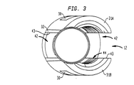
図3〜図16は、本発明のある特定の好ましい実施形態による骨固定組立体を示している。骨固定組立体は、脊柱の椎体の茎部に固定可能である。図3〜図7において、固定組立体は、好ましくは外科装置に通常用いられる任意の金属であり、特に例えばチタンまたはステンレススチールなどの骨用ねじおよび骨用ピンに用いられる任意の金属である生物学的に不活性の材料から好ましくは構成されている。結合エレメントに適するその他の材料としては、合金、複合材料、セラミックあるいはカーボンファイバ材料を含んでいる。結合エレメント12は、上端14および下端16を有している。上端14は第1の平面23を形成し、下端16は第2の平面25を形成しており、第1の平面23と第2の平面25とは、好ましくは、互いに交差している。
【0035】
結合エレメント12は、上端14から中間領域20へ延びる第1の部分18と、中間領域20から下端16へ延びる第2の部分21とを含んでいる。第1の部分18はこれを通って延びる第1の孔を有しており、第1の孔は第1の長手軸線22と同軸である。第2の部分21はこれを通って延びる第2の孔を有しており、第2の孔は第2の長手軸線24と同軸である。第1の長手軸線22と第2の長手軸線24とは、好ましくは、互いに対して角度を成している。その結果、第1の部分18を通って延びる第1の孔の向きは、第2の部分21を通って延びる第2の孔に対して平行でない、すなわち傾いている(図4参照)。
【0036】
図4において、第1の長手軸線22と第2の長手軸線24との間に形成されている角度αは、0゜よりも大きく90゜未満までの任意の角度を成し得る。特定の角度αは、固定組立体10の特定の用途に依存することもある。好ましくは、角度αはほぼ20〜30゜である。より好ましい実施形態では、角度αはほぼ25゜±2゜である。非常に好ましい実施形態では、角度αはほぼ24゜である。結合エレメント12は1つの組で設けられることもあり、各結合エレメント12は、他とは僅かに異なる形状と唯一の角度とをそれぞれ有している。手術中、手術者は、この集合から、特定の患者および/または患者の脊髄に沿って位置する個所のうちで、ある特定の個所に適する角度を有する結合エレメントを選択できる。
【0037】
結合エレメント12は、3つ以上(例えば3つ)の柱体を有する多軸構造体等の他の形状を有することもあり、各柱体は、その他の柱体に対して横断方向に位置している。別の好ましい実施形態では、柱体は、例えば正方形、多角形、楕円形などの円形でない横断面を有している。
【0038】
また、図5〜図7において、結合エレメント12は、望ましくは、略柱体外面26を有しており、略柱体外面26は、上端14から延びて下端16に隣接して位置する凸面28に達している。結合エレメント12は、好ましくは、外面26内に形成されている1つ以上のノッチ30も含み、これにより結合エレメント12は、例えばパースエイダー装置などの工具により固定できることになる。ノッチ30は、好ましくは、第1の長手軸線22に対して横断方向に位置する方向に延びている。
【0039】
図7において、結合エレメント12は、第1の孔40を包囲する内面38を有し、内面38は上端14から下端16へ延び、好ましくは、第1の長手軸線22と同軸である。内面38は、好ましくは、上端14から下端16へ延びる雌ねじ44を含んでいる。結合エレメント12は、下端16から上端14へ延びる第2の孔41を有している。第2の孔41は、第2の長手軸線24と同軸に位置している。
【0040】
図5〜図6において、結合エレメント12は、外面26から内面38へ延びる一対の棒受入れ開口部42を有し、各棒受入れ開口部42は、第1の孔40と連通している。棒受入れ開口部42は、整形外科的安定化棒を中に捕捉して座らせるものである。棒受入れ開口部42は、好ましくは、結合エレメント12の上端14に隣接して位置する開放端と、該開放端から遠くに位置する閉鎖端とをそれぞれ有するU形開口部を構成している。
【0041】
棒受入れ開口部42により結合エレメント12は、開口部42の片側に位置する第1のアーム31Aと、棒受入れ開口部42の反対側に位置する第2のアーム31Bとに分割されている。棒受入れ開口部42は、好ましくは、結合エレメント12の外面26に隣接して形成されているカット32を含んでいる。本発明は、手術のいかなる特定の理論によっても制限されないが、カット32により、2つ以上の結合エレメント12は、カットが設けられていない結合エレメントに比して相互間隔がより短く、したがってより密集して配置できることになる。
【0042】
図6および図7において、結合エレメント12は、好ましくは、上端14から内側キャビティ46へ延びる面取り部45を有している。面取り部45は、好ましくは、棒受入れ開口部42のうちの1つの開放面43から延びて第1の部分18上の内面38へ達している。面取り部45の効果により係留エレメントを結合エレメント12に挿入するのが容易になる利点は、第1の孔40が第2の孔41に対して角度を成すにもかかわらず得られることである。ある特定の好ましい実施形態では、面取り部45は、結合エレメント12を成す材料を中ぐりして、第2の孔41および第2の軸線24と実質的に同軸の第3の軸線を中心軸線として有するように形成されている。面取り部43により、好ましくは、係留エレメントを骨に入れて固定する際に通過する係留エレメントおよびドライバ用の空間が得られる。別の好ましい実施形態では、結合エレメントおよび係留エレメントの寸法は、係留エレメントを結合エレメントに挿入することが面取り部を設けずに行い得るように選択されている。
【0043】
図7において、結合エレメント12は、下端16に隣接して位置し、係留エレメントと係合する座部50を含んでいる。座部50は、好ましくは、円錐形を有し、座部50の側壁52の内部空間は、下端16へ向かって先細りになっている。別の好ましい実施形態では、座部50は略球状あるいは略凸状である。
【0044】
図8〜図9において、固定組立体は、好ましくは、係留エレメント52、例えばねじ付ファスナなどを含んでおり、この係留エレメント52は、骨に挿入する先端54と、係留エレメント52の上端に位置する頭部56と、先端54および頭部56の間で延びる雄ねじ58とを有している。ねじ58は、内径64および外径66を有している。ねじ58は、望ましくは、頭部56とねじ58との間に好ましくは位置する首部60で終端している。首部60は、ねじ58の外径66よりも小さい首部直径68を有している。首部60の直径をこのように小さくすると、結合エレメント12は、係留エレメント52に対してより広い運動範囲にわたり旋回および回転できるようになっている。ねじ58、首部60および頭部56を含む係留エレメント52は、好ましくは、例えばチタンあるいはステンレススチールなどの生物学的に不活性の材料から構成されている。
【0045】
頭部56は、望ましくは、骨に係留エレメント52をねじ込むのに用いるドライバと協働し得る1つ以上の凹部あるいは溝70を含んでいる。頭部56の寸法および形状は、好ましくは、頭部56が結合エレメント12内に形成されている第1および第2の孔を通過し、頭部56の下面が結合エレメントの座部(図7)と係合するまでに行われるように決められる。頭部56の下面57は、好ましくは、座部50と係合できるように凸状あるいは球状に形成されている。頭部56の下面57が座部50と係合すると、係留エレメント52の先端54とねじ部分58とが、結合エレメント12の下端16に位置する第2の孔41(図7)を通って延びている。
【0046】
図10〜図12において、係留エレメント52を結合エレメント12と一緒になるように組立てる1つの好ましい方法では、係留エレメント52の先端54を第1の孔40に通して、ねじ58が結合エレメント12の下端16から突出するようにしている。ある特定の好ましい実施形態では、ねじ58の外径が第1の孔40の直径よりも小さいから、係留エレメント52は第1の孔40を自由に通れるようになっている。別の好ましい実施形態では、ねじ58の直径は第1の孔40の直径とほぼ同一であり、したがって、頭部56の下面57が座部50と係合するまで、係留エレメント52を結合エレメント12にねじ込む必要がある。ある特定の好ましい実施形態では、頭部56の下面57は球状であり、座部は円錐形である。別の実施形態では、頭部56の下面57と座部50とは例えば凸状下面および凹状座部などの他の形状を成している。
【0047】
図13および図14において、係留エレメント52を結合エレメント12と一緒になるように組立てると、係留エレメント52および結合エレメン12は、互いに対して自由に旋回および回転できるようになる。係留エレメント52の首部60は、好ましくは、直径を小さくされ、外面62が凹状であり、これにより係留エレメント52と結合エレメント12とが互いに対して旋回する際の角度範囲は、首部の直径が小さくされていない係留エレメントに比してより広くなる。図13が示す結合エレメント12は、係留エレメント52に対して第1の位置にある。図14に示すように、結合エレメント12が係留エレメント52に対して第2の位置をとることは、図13に示されている位置に対して結合エレメント12を逆時計回りに回転させることにより行われる。
【0048】
係留エレメント52と結合エレメント12とを一緒になるように組立てた部分組立体は、骨80に挿入できる状態にある。1つの好ましい実施形態では、パイロット穴が骨に穿孔され、係留エレメント52がドライバあるいは工具を用いてパイロット穴に入れられて骨80にねじ込まれるようになっている。係留エレメント52はドライバにより回転され、係留エレメント52は長手方向に前進して骨80に入る。係留エレメント52を骨80に入れて前進させるのは、好ましくは、係留エレメント52が適所にしっかり固定されるまで、例えば係留エレメント52の首部60が骨80に隣接して位置するようになるまで行われる。別の好ましい実施形態では、先端は、例えば切削溝などの切刃が中に設けられ、これによりパイロット穴を前もって形成することは不要になる。
【0049】
係留エレメント52を骨80に入れて中に係留させても、依然として結合エレメント12は、係留エレメント52に対して自由に旋回および回転でき、したがって整形外科的安定化棒82は、結合エレメント12の棒受入れ開口部42内に入れて捕捉可能となる。ある特定の好ましい実施形態では、係留エレメントを骨に完全に挿入した後、間隙が結合エレメント12の下端16と骨80との間に存在する。この間隙により、好ましくは、結合エレメント12が係留エレメント52に対して旋回および回転するのが容易となる。別の好ましい実施形態では、棒82が結合エレメント12により捕捉されると、結合エレメント12の下端16が安定化操作の間に骨と係合することになる。しかしながら、これらの実施形態では、結合エレメント12の下端16が骨に接触することは、高信頼性の組立体を形成するために問題とならない。別の好ましい実施形態では、結合エレメント12の下端16が骨と係合しないと、高信頼性の安定した組立体が得られないこともある。結合エレメント12は、工具で結合エレメント12を把持することにより動かせる(例えば、旋回させる)。
【0050】
図15において、棒82を結合エレメント12内に入れて位置決めした後、ロックエレメント84の下面85が棒82に当るまで、雄ねじを有する例えば押しねじなどのロックエレメント84を結合エレメント12の雌ねじ44にねじ込まれる。次いで、ロックエレメント84をさらに締付け、棒82が棒受入れ開口部42の閉鎖端に当るようにする。締付けられたロックエレメント84は、棒82を介して下方へ作用する力を頭部56の上面59に加える。別の実施形態では、結合エレメント12の外面26にねじが形成され、ロックエレメントは、雌ねじが形成されたスリーブを成している。
【0051】
図15〜図16において、棒82が、下方へ作用する力を頭部56の上面59に加えると、頭部56の下面57は、結合エレメント12の座部50に入る。座部50が円錐形であり、下面57が球状である実施形態では、下面57が座部50に係合すると、球状表面と円錐形表面とが摩擦により互いにロックされ、これにより結合エレメント12の位置が頭部56に対してロックされ、それにより結合エレメント12と係留エレメント52とが互いに対してさらに旋回および回転し得ないことになる。本発明は、手術に関するいかなる特定の理論によっても制限されないにもかかわらず、頭部56の下面57が結合エレメント12の円錐形座部と係合することは、凸面と凹面との間の境界面に比して大幅な改善であり、ねじ頭部と結合エレメントとの間の境界面に加えられるロック力を大幅に改善するものである。別の実施形態では、座部50および頭部56の下面57は両方共に球状である。
【0052】
従来技術では、幾人かの患者は比較的小さい脊椎を有するので、この場合、2つ以上の骨固定組立体を互いに隣接して位置する脊椎にわたり互いに隣接させて固定するのが困難であった。その結果、幾人かの患者では、1つ以上の脊椎に安定化組立体の一部分が取付けられなかった。これにより1つの脊髄部分の安定化および融合が悪影響を受けることもあった。何故ならば、脊髄部分の全体が安定化されていないからである。本発明は、手術に関するいかなる特定の理論によっても制限されないが、棒受入れ開口部42に隣接して位置するカット32を形成すると、結合エレメント12の横断面または幅が小さくなり、これにより、一連の結合エレメントが脊髄棒により互いに接続された際に、近傍の結合エレメントとの干渉を最小化することが可能となる。カット32により結合エレメントは、より密集して配置され、これによりある1つの脊髄部分の融合が改善されることになる。また、結合エレメント12にカット32を形成すると、患者の組織を刺激したり、医療関係者の手術用手袋を切裂くこともある鋭い端縁の発生も最小化されることになる。
【0053】
ある特定の好ましい実施形態では、係留エレメントの頭部は、好ましくは、第1の半径方向表面を形成する下面と、第2の半径方向表面を形成する上面とを有し、この様子は、米国特許出願第09/755,846号に記載のある特定の実施形態に開示され、この明細書は、引用することにより本明細書の一部を成すものとする。第2の半径方向表面の半径は、第1の半径方向表面の半径よりも小さく、これにより、組立体の全体的輪郭が低くなる。
【0054】
図18〜図22において、別の好ましい実施形態では、結合エレメント122は、第1の長手軸線122と同軸の第1の部分118を通って延びる第1の孔40と、第2の長手軸線124と同軸の第2の部分121を通って延びる第2の孔141とを含んでおり、第1の長手軸線と第2の長手軸線とは、0゜よりも大きく90゜未満の任意の角度を成し得る角度βを形成している。好ましくは、20〜30゜の角度が用いられる。より好ましい実施形態では、角度βは、好ましくは約25゜±2゜である。非常に好ましい実施形態では、角度βは、好ましくは24゜である。
【0055】
また、本発明は、好ましくは、2001年1月5日提出の米国特許出願第09/755,846号に記載のある特定の実施形態に開示されているものなどのドライバを含んでおり、この明細書は、引用することにより本明細書の一部を成すものとする。ドライバは、好ましくは、回転可能シャフトと、1つ以上のフィンガとを有し、フィンガは、シャフトの一端から延び、係留エレメントの頭部内の溝と係合し得るようになっている。好ましい実施形態では、ドライバは係留エレメントの頭部内に各溝に対してそれぞれ1つのフィンガを有している。また、ドライバのシャフトには雄ねじが形成されていることもあり、該雄ねじは、係留エレメントが骨に係留されると、結合エレメントの雌ねじと係合することになる。ドライバの雄ねじと、結合エレメントの雌ねじとが係合することにより、一般に係留エレメントが骨に固定されると、組立体が安定化されることになる。特に、雄ねじと雌ねじとを係合することにより、係留エレメントを骨内にドライバによりねじ込んで、係留エレメントを骨に係留するのを容易にすると、結合エレメントが係留エレメントに対して動くのを阻止することになる。
【0056】
係留エレメントは、1999年10月7日付出願の一緒に譲渡された米国特許出願第09/414,272号(’272特許と略す)に記載のある特定の好ましい実施形態に開示されている広げ可能頭部などを有することもあり、この明細書は、引用することにより本明細書の一部を成すものとする。広げ可能頭部は、凹部と、頭部の内面と外面との間で延びる少なくとも1つのスロットとを有し、これにより頭部を広げるのが容易になる。また、’272特許の係留エレメントは、凹部内に少なくとも部分的に配置されるインサートも有し、該インサートは、外面を有し、凹部の内のり寸法よりも大きい外のり寸法を形成している。脊髄棒を結合エレメント内に入れると、この結合エレメントに対応するロックエレメントが棒受入れ開口部に整形外科的棒を入れてロックする。ロックエレメントの作用により整形外科的棒は、棒受入れ開口部に入り、これによりインサートは広げ可能頭部の凹部に入る。インサートが凹部に入れられると、インサートの外のり寸法は、頭部の内のり寸法に押し当たり、これにより頭部の外面が広げられて結合エレメントの座部に当り、これにより結合エレメントはロックされて、さらに旋回することができなくなる。
【0057】
図23に示すように、茎部固定組立体110A,110Bは、互いに隣接して取付けられ、これにより脊髄棒82と係合することになる。図24に示すように、係留エレメント152A,152Bは、結合エレメント112A,112Bに対して適所でロックされ、これにより、xy平面またはxz平面またはyz平面内で脊髄棒82に対して角度を成すことになる。
【0058】
図25〜図27に示す結合エレメント212は、本発明の別の1つの好ましい実施例による茎部固定組立体のためのものである。結合エレメント212は、上端214および下端216を有し、上端214は第1の平面223を形成し、下端216は第2の平面225を形成しており、第1の平面223と第2の平面225とは互いに交差している。
【0059】
図26〜図27において、結合エレメント212は、上端214から中間領域220へ第1の軸線222に沿って延びる第1の孔240と、結合エレメント212の下端216から中間領域220へ第2の軸線224に沿って延びる第2の孔241とを有している。第1の孔240と第2の孔241とは、一般に、互いに対して平行でないかまたは横断方向に位置している。
【0060】
第1の孔240と同軸の第1の軸線222と、第2の孔241と同軸の第2の軸線224との間の角度θは、0゜よりも大きく90゜未満の任意の角度を成し得る。角度θは、結合エレメント212を用いる特定の用途に依存して変化することもある。好ましくは、角度θはほぼ20〜30゜である。より好ましい実施形態では、角度θはほぼ25゜±2゜である。非常に好ましい実施形態では、角度θはほぼ24゜である。
【0061】
図25において、結合エレメント212の外面226は、望ましくは、円柱形であり、上端214から下端216へ延びている。外面226内には、好ましくは、2つ以上のノッチ230が形成され、これにより、結合エレメント212を把持および/または操縦することが、固定エレメントあるいは工具を用いてできるようになっている。ノッチ230は、好ましくは、第1の長手軸線222と交差する方向に延びている。
【0062】
図25〜図27において、結合エレメント212の第1の部分218は、好ましくは、上端214から下端216へ延びる雌ねじ244を含んでいる。結合エレメント212は一対の棒受入れ開口部242を有し、該棒受入れ開口部242は、結合エレメント212の外面226から内面238へ延びる第1の孔240と連通している。棒受入れ開口部242内には脊髄棒(図示せず)が座らせられる。棒受入れ開口部242は、好ましくは、上端214に隣接して位置する開放端と、該開放端に対向して位置する閉鎖端とを有するU形開口部を成している。棒受入れ開口部242は、結合エレメント212を第1のアーム231Aと第2のアーム231Bとに分割している。
【0063】
結合エレメント212は、第2の部分221内に位置するキャビティ246と、係留エレメントと係合する座部250とを有している。図26に示すある特定の好ましい実施形態では、座部250は側壁252を含む円錐形座部であり、側壁252は下端216へ向かって延びて下端216に隣接するまで互いへ向かって近づくので、側壁252の内部空間は先細りになっている。別の好ましい実施形態では、座部250は略球状あるいは略凹状であることもある。
【0064】
図28Aおよび図28Bが示す金属ブランク310すなわち半加工品は、本発明の別の好ましい実施形態による結合エレメントを形成するのに用いられる。金属ブランク310は、好ましくは、円柱形外面326と、長手軸線A−Aと、面取りされている下端316とを有している。金属ブランク310は、上端314から下端316へ向かって中ぐりされ、長手軸線A−Aと同軸の第1の孔340を形成している。
【0065】
図29〜図31において、結合エレメント312は、互いに対向して位置するアーム331A,331Bを互いから離間させる棒受入れ開口部342を有している。結合エレメント312は、互いに対向して位置するアーム331A,331Bのそれぞれに一対の把持ノッチ30A,30Bを含む外面326を有している。互いに対向して位置する把持ノッチ330A,330Bは、鉗子(図示せず)などの工具により固定可能となっている。
【0066】
図30〜図31において、互いに対向して位置する2対の把持ノッチ330A,330Bは、結合エレメント312のそれぞれのアーム331A,331B内に削成されている。ある特定の好ましい実施形態では、把持ノッチ330A,330Bは、ウッドラフカッターなどのロータリーカッターを用いて形成されており、その際、ロータリーカッターは、結合エレメント312の外面326に対して横方向に当てられる。第1のアーム331Aに位置する第1の対の把持ノッチ330Aは、その間で延びる第1のリブ333Aにより互いから離間されている。同様に、第2のアーム331Bに位置する第2の対の把持ノッチ330Bは、第2のリブ333Bにより互いから離間されている。
【0067】
結合エレメント312を通って2つの孔が延びている。第1の孔340は、軸線A−Aに略平行な方向に延びる。第1の孔340は、好ましくは、結合エレメント312の上端314から下端316にかけて穿孔することにより形成されている。また、結合エレメント312は、軸線B−Bに沿って下端316から上端314へ延びる第2の孔341も含んでいる。ある特定の好ましい実施形態では、第1および第2の孔340,341は、結合エレメント312の全長を完全に通り抜けず、上端314と下端316との間の中間領域で互いに合流している。
【0068】
図31において、第1の孔340は軸線A−Aと同軸であり、第2の孔341は軸線B−Bと同軸である。第1の孔340は、結合エレメント312の上端314から下端316にかけて延び、第2の孔341は、下端316から上端314にかけて延びている。結合エレメント312の上端314は、第1の平面423を形成し、下端316は第2の平面425を形成している。第1の平面423と第2の平面425とは、好ましくは、互いに対して角度を成し、互いに交差している。
【0069】
図32Aが示す結合エレメント312は、その下端316から出発して形成され、軸線B−Bに沿って延びる第2の孔341を含んでいる。図32Bにおいて、第1の孔340は軸線A−Aと同軸であり、第2の孔341は軸線B−Bと同軸である。結合エレメント312は、上端314から下端316へ延びる雌ねじ344を含んでいる。下端316に隣接して位置する、結合エレメント312の外面は、好ましくは、面取りされている。ある特定の好ましい実施形態では、面取り表面は結合エレメント312を軸線B−Bを中心として回転させ、下端316を研削工具と係合させて形成されている。結合エレメント312の中間領域321は、係止リップ343を含んでいる。以下に詳細に説明するように、係止リップ343は、結合エレメントと係留エレメントを一緒になるように組立てた後に、ねじ付ファスナなどの係留エレメントと結合エレメント312との組立てが分解されのを阻止するものである。結合エレメント312の下端316内に形成された第2の孔341は、好ましくは、先細りする方向へ進むにつれて互いへ向かって近づく側壁352を有する座部350を含んでいる。図32B−1に示すように、側壁352と軸線B−Bとは、好ましくは、ほぼ8〜12゜の角度を成し、より好ましくは、約10゜の角度を成している。
【0070】
また、図33〜図35Bにおいて、本発明の茎部ねじ組立体は、先端354と、先端354から遠くに位置する頭部356とを有する係留エレメント352も含んでいる。ある特定の好ましい実施形態では、頭部356は球形を成している。頭部356は、その外面内に形成され等間隔に位置するカット370を含んでいる。ある特定の好ましい実施形態では、互いに間隔を置いて位置するカット370は、研削工具あるいはフライス工具を側方から頭部に係合させて形成されている。締付け固定エレメント352は、外径366および内径364を有する雄ねじ358を含んでいる。また、締付け固定エレメント352は、ねじ358の上端と頭部356との間に設けられている首部360も含んでいる。首部360は凹面362を有している。締付け固定エレメント352は、先端354に隣接して形成されている例えば切削溝などの切削面371も含んでいる。当業者に知られているように、締付け固定エレメント352の先端354に切削溝371を形成すると、骨に前もって雌ねじを切る必要がなく、これにより締付け固定エレメント352と骨との間の嵌合が、より締まってぴったりとなる。締付け固定エレメント352を骨にねじ込むと、切削溝371が骨に切込まれ、これにより骨に前もって雌ねじを切る必要がなくなる。締付け固定エレメント352を骨にねじ込むと、頭部356上に等間隔に位置するカット370は、ドライバのフィンガにより係合され、この様子は、以下に詳細に説明する。
【0071】
また、図36A〜図36Cにおいて、固定組立体は、好ましくは、上端392、下端394およびこれら上下端の間で延びる雄ねじ396を有する押しねじ390などのロックエレメントも含んでいる。押しねじ390は、上端392から下端394へ延びる六角形開口部398を含み、開口部398は、六角形ドライバの一端を受け入れ、これにより押しねじ390を回すようになっている。以下に詳細に説明するように、押しねじ390の下面394は、整形外科的安定化棒に当って、係留エレメントの頭部に下方へ作用する力を加え、これにより固定組立体はロックされて、さらに動くことができなくなる。
【0072】
図37A〜図39Aは、結合エレメント312、ねじ付ファスナ352および押しねじ390を含む固定組立体を示し、これらのコンポーネントは、まだ一緒になるように組立てられていない。1つの好ましい実施形態では、ねじ付ファスナ352の先端354は、結合エレメント312の上端314から延びる第1の孔340を通り抜けるようになっている。ある特定の実施形態では、ねじ付ファスナ352の雄ねじ358が結合エレメント312の雌ねじ(図示せず)を通過するには、雄ねじ358をねじ込まれなければならないが、別の好ましい実施形態では、ねじ部分358が当該雌ねじを通過するのに、ねじ付ファスナ352のねじ部分358が該雌ねじの下端を通過するまでねじ部分358を前後に揺動させている。ねじ付ファスナ352のねじ358が結合エレメント312の雌ねじを通過すると、ねじ付ファスナ352の頭部356は、結合エレメント312の下端316に隣接して位置する座部350にプレス嵌めされて入り込むことになる。ねじ付ファスナ352の頭部356は、好ましくは、係止リップ343に位置する孔の直径よりも僅かに大きい直径を有している。頭部356が押されて係止リップ343を通過すると、係止リップ343は僅かに変形され、これにより頭部356は、座部350に入り込むことが可能になる。いったん頭部356が係止リップ343を通過すると、係止リップ343は、頭部356の外径よりも小さい直径に弾力的に戻る。その結果、頭部356は、係止リップ343と、結合エレメント312の下端316に位置する開口部との間で、結合エレメント312の座部350内に捕捉されることになる。いったん頭部356が座部350内に捕捉されると、ねじ付ファスナ352と結合エレメント312とは、互いに対して旋回および回転できることになる。
【0073】
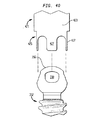
図40〜図42において、係留エレメント352の頭部356が結合エレメントの座部350内に捕捉されると、骨固定組立体は、骨に入れて中に係留し、整形外科的安定化棒と結合する状態になる。1つの好ましい実施形態では、下端425から突出している間隔を置いたフィンガ427付きの下端425を有するシャフト423を含むドライバ421は、ねじ付ファスナ352の頭部356とほぼ心合せされて頭部356の上を覆うように配置されている。フィンガ427は、好ましくは、ほぼ剛性であり、これによりフィンガ427が撓むあるいは曲がるのを制限する作用は、力がフィンガに加えられると生じることになる。そしてフィンガ427は、頭部356の、互いに間隔を置いたカット330内に座っている。また、ドライバ421は、雄ねじ429を有するシャフト423も含み、雄ねじ429は、結合エレメント312の雌ねじ344と噛合し、これにより、ねじ付ファスナ352が骨にねじ込まれる際に、結合エレメント312とねじ付ファスナ352とを安定化させることになる。ドライバ421は、好ましくは、シャフト423に沿ってスライド可能であるスリーブ425も含み、締付け固定エレメント352が骨にねじ込まれる際に結合エレメント312の外面326上をスライドして固定組立体をさらに安定化させることになる。
【0074】
本明細書における本発明は、ある特定の実施形態を参照して説明されたが、これらの実施形態は、本発明の原理および用途を例示的に示すに過ぎない。したがって、多数の変更が、本明細書に開示されている実施形態に対して行われ、別の配置が添付の特許請求の範囲により定められた本発明の精神および範囲から逸脱することなしに案出される。
【0075】
[工業的用途の可能性]
本発明は、整形外科関連産業に用途を持つものである。
【図面の簡単な説明】
【図1】従来の骨固定組立体を示す側面図である。
【図2】本発明のある特定の好ましい実施形態によるものであって、整形外科的安定化棒と結合された一対の骨固定組立体を示す簡略図である。
【図3】本発明の1つの好ましい実施形態による、骨固定組立体の結合エレメントの上面図である。
【図4】図3の結合エレメントの左側側面図である。
【図5】図3〜図4の結合エレメントの前方側正面図である。
【図6】図3〜図5の結合エレメントの斜視図である。
【図7】図5の7−7切断線に沿って切断して示す図5の結合エレメントの横断面図である。
【図8】本発明のある特定の好ましい実施形態による係留エレメントの前方側正面図である。
【図9】図8の係留エレメントの上面図である。
【図10】図3〜図7の結合エレメントと一緒になるように部分的に組立てられた、図8〜図9の係留エレメントを部分的に断面で示す右側側面図である。
【図11】1つのさらなる組立てステップの間における、図10の結合エレメントおよび係留エレメントを部分的に断面で示す右側側面図である。
【図12】図11の結合エレメントおよび係留エレメントを部分的に断面で示す右側側面図であり、係留エレメントは結合エレメント内に完全に座っている。
【図13】図10〜図12の結合エレメントおよび係留エレメントを部分的に断面で示す右側側面図であり、係留エレメントは骨内に固定されている。
【図14】図13の結合エレメントおよび係留エレメントを部分的に断面で示す右側側面図であり、結合エレメントは、係留エレメントの頭部を中心として旋回されている。
【図15】図14の骨固定組立体を部分的に断面で示す右側側面図であり、脊髄棒は、結合エレメント内に捕捉され、ロックエレメントにより適所に保持されている。
【図16】図15の結合エレメント、係留エレメント、ロックエレメントおよび脊髄棒を部分的に断面で示す前方側正面図である。
【図17】本発明の別の1つの好ましい実施例による骨固定組立体の係留エレメントの横断面図である。
【図18】本発明の別の1つの好ましい実施例による骨固定組立体の結合エレメントの斜視図である。
【図19】図18の結合エレメントの右側側面図である。
【図20】図18〜図19の結合エレメントの上面図である。
【図21】図20の21−21切断線に沿って切断して示す、図20の結合エレメントの横断面図である。
【図22】図21の22−22切断線に沿って切断して示す、図21の結合エレメントの横断面図である。
【図23】本発明の好ましい実施形態によるものであって、安定化棒に固定された2つの骨固定組立体の正面図である。
【図24】図23の2つの骨固定組立体の斜視図である。
【図25】本発明のさらなる好ましい実施形態による、骨固定組立体の結合エレメントの斜視図である。
【図26】図25の結合エレメントの横断面図である。
【図27】図26のB−B軸線に沿って切断して示す、図26の結合エレメントの上面図である。
【図28】AおよびBは、本発明のある特定の好ましい実施形態による骨固定組立体の結合エレメントを形成するのに用いるブランクすなわち半加工品をそれぞれ示す上面図および側面図である。
【図29】本発明のある特定の好ましい実施形態による結合エレメントを示す前方側正面図である。
【図30】図29の30−30軸線に沿って切断して示す、図29の結合エレメントの上面図である。
【図31】図29の結合エレメントを示す側面図である。
【図32】Aは図31のB−B軸線に沿って切断して示す図31の結合エレメントの上面図、Bは図32Aの32B−32B切断線に沿って切断して示す図32Aの結合エレメントの横断面図、B−1は図32Bに示されている結合エレメントの一部分を示す拡大図である。
【図33】本発明のある特定の好ましい実施形態による骨固定組立体の係留エレメントを示す斜視図である。
【図34】図33の係留エレメントの上面図である。
【図35】AおよびBは図33の係留エレメントをそれぞれ示す側面図および横断面図である。
【図36】A〜Cは本発明のある特定の好ましい実施形態によるものであって、図29〜図32B−1の結合エレメントにねじ込まれるロックエレメントをそれぞれ示す斜視図、上面図および横断面図である。
【図37】Aは本発明のある特定の好ましい実施形態によるものであって、結合エレメントと締付け固定エレメントとロックエレメントとを含む骨固定組立体を示す分解図、Bは結合エレメントと係留エレメントとロックエレメントとが一緒になるように組立てられた後の図37Aの骨固定組立体を示す側面図である。
【図38】結合エレメントと係留エレメントとロックエレメントとが一緒になるように組立てられた後の図37Aの骨固定組立体を示す前方側正面図である。
【図39】図37Bの骨固定組立体を示す横断面図である。
【図40】本発明のある特定の好ましい実施形態によるものであって、係留エレメントの頭部と係合する互いに間隔を置いて位置する複数のフィンガを有する下端を含むドライバの断片図である。
【図41】係留エレメントの頭部と係合する、図41のドライバの横断面図である。
【図42】係留エレメントの頭部と係合する、図42のドライバの斜視図である。
【符号の説明】
12 結合エレメント
14 上端
16 下端
22 第1の長手軸線
24 第2の長手軸線
40 第1の孔
41 第2の孔
50 座部
52 係留エレメント
54 先端
56 頭部
58 ねじ
Claims (29)
- 第1の長手軸線と同軸の第1の孔と、第2の長手軸線と同軸の第2の孔とを形成する内面を有する結合エレメントであって、前記第1の長手軸線と前記第2の長手軸線とは、互いに交差し連通している結合エレメントであり、
前記結合エレメントは、当該結合エレメントの上端から当該結合エレメントの下端へ向かって延び、安定化棒を受け入れるようになっているU形開口部を備え、当該結合エレメントの下端に隣接して位置し、当該結合エレメントの前記内面により形成される座部を含んでおり、
前記結合エレメントと一緒になるように組立てられ、骨に挿入する第1の端部と、該第1の端部から離れて位置し前記結合エレメントの座部に当接する頭部とを有する係留エレメントと、
を備えた、骨固定組立体。 - 前記結合エレメントは上端および下端を有し、前記第1の孔は前記上端から前記下端へ向かって延び、前記第2の孔は前記下端から前記上端へ向かって延びている、請求項1に記載の組立体。
- 前記第1および第2の孔は、前記結合エレメントの前記上端と前記下端との間で互いに連通している、請求項2に記載の組立体。
- 前記結合エレメントの前記上端は第1の平面を形成し、前記結合エレメントの前記下端は第2の平面を形成し、前記第1の平面と前記第2の平面とは互いに交差している、請求項2に記載の組立体。
- 前記係留エレメントは、前記結合エレメントの前記下端から突出している、請求項2に記載の組立体。
- 前記係留エレメントは、前記結合エレメントと一緒になるように組立てられた1つの別個の部材であり、これにより前記結合エレメントと前記係留エレメントとが互いに対して移動可能である、請求項1に記載の組立体。
- 前記第2の孔は、前記結合エレメントの前記下端に隣接する座部を含み、該座部は、前記係留エレメントと係合可能である、請求項2に記載の組立体。
- 前記係留エレメントは、前記座部と係合できる略球状下面を有する頭部を備えている、請求項7に記載の組立体。
- 前記座部は、前記結合エレメントと前記係留エレメントとが互いに対して旋回するのを容易にするような形状に形成されている、請求項8に記載の組立体。
- 前記座部は、前記結合エレメントの前記下端へ向かって内方に傾いている側壁を備えた略円錐形である、請求項9に記載の組立体。
- 前記座部は、前記頭部の球状下面と係合可能な略凹状表面を有している、請求項9に記載の組立体。
- 前記結合エレメント内に安定化棒を固定するように前記結合エレメントと係合可能なロックエレメントをさらに備えている、請求項1に記載の組立体。
- 前記係留エレメントは、前記結合エレメントと前記係留エレメントとが互いに対して旋回するのを容易にするために、前記ねじ部の直径よりも小さい直径を有する前記頭部に隣接して位置する首部を含んでいる、請求項8に記載の組立体。
- 前記首部は、凹面を含んでいる、請求項13に記載の組立体。
- 前記係留エレメントに対して前記結合エレメントの位置をロックするように、前記結合エレメントと係合可能なロックエレメントをさらに備えている、請求項8に記載の組立体。
- 前記ロックエレメントは、前記安定化棒が前記結合エレメントの前記下端へ向かって動くように作用し、これにより前記結合エレメントは、前記係留エレメントの前記頭部が前記結合エレメントと前記係留エレメントとを互いに対してさらに動くのをロックすべく前記座部に当るように作用する、請求項15に記載の組立体。
- 前記結合エレメントは、外面、上端および下端を有し、前記棒受入れ開口部は、前記上端から延びて前記下端へ向かい、前記結合エレメントは、当該結合エレメントの幅を最小化するために、前記外面と前記棒受入れ開口部との間にカットを備えている、請求項1に記載の組立体。
- 前記係留エレメントは、骨と係合するフックまたはかかりを備えている、請求項1に記載の組立体。
- 前記係留エレメントは、その前記第1の端部から第2の端部へ向かって延びるねじを有するねじ付ファスナである、請求項1に記載の組立体。
- 前記結合エレメントは、前記係留エレメントを前記結合エレメントと一緒になるように組立てるのを容易にするために、前記第1の孔に隣接して位置する面取り部を含んでいる、請求項7に記載の組立体。
- 上端および下端を有する結合エレメントであり、
前記結合エレメントの前記上端から前記下端へ向かって延びる第1の部分であって、第1の長手軸線と同軸の第1の孔を含んでいる第1の部分と、
前記結合エレメントの前記下端から前記上端へ向かって延びる第2の部分であって、前記第1の長手軸線と交差する第2の長手軸線と同軸の第2の孔を有する第2の部分と、
前記結合エレメントの前記上端から前記下端へ向かって延び、整形外科的安定化棒を受け入れるU形棒受入れ開口部と、
前記結合エレメントは、前記第1及び第2の孔を形成する内面と、当該結合エレメントの下端で前記第2の孔に隣接して位置する座部とを備え、
骨に挿入する第1の端部と、該第1の端部から離れて位置し前記結合エレメントの座部に当接する頭部とを有する係留エレメントと、
を備えた、結合エレメント。 - 前記第2の孔は、前記結合エレメントの前記下端に隣接して位置する座部を含んでいる、請求項21に記載の結合エレメント。
- 前記座部は、前記結合エレメントにより固定された係留エレメントの頭部と係合可能であり、これにより前記結合エレメントと前記係留エレメントとが互いに対して旋回できるようになっている、請求項22に記載の結合エレメント。
- 前記座部は、前記係留エレメントの前記頭部の下面と係合可能である、請求項23に記載の結合エレメント。
- 前記座部は、内方に傾斜する円錐形を有しているかまたは凸状形を有している、請求項21に記載の結合エレメント。
- 前記結合エレメントは前記第1および第2の孔を形成する内面を含み、前記棒受入れ開口部は略U形の開放面により形成され、前記開放面のうちの1つから前記内面へ延びる面取り部をさらに備えている、請求項23に記載の結合エレメント。
- 前記内面は、前記結合エレメントの前記棒受入れ開口部内に整形外科的棒を固定するためにロックエレメントと係合し、前記結合エレメントの前記上端に隣接して位置するねじを含んでいる、請求項23に記載の結合エレメント。
- 前記ロックエレメントは、前記結合エレメントの前記雌ねじにねじ込みする雄ねじを有している、請求項27に記載の結合エレメント。
- 前記結合エレメントは、整形外科的棒に対して前記結合エレメントを位置決めするための計器により係合させるノッチを備えた外面を有している、請求項21に記載の結合エレメント。
Applications Claiming Priority (4)
| Application Number | Priority Date | Filing Date | Title |
|---|---|---|---|
| US32204201P | 2001-09-14 | 2001-09-14 | |
| US60/322042 | 2001-09-14 | ||
| US10/091068 | 2002-03-05 | ||
| US10/091,068 US6974460B2 (en) | 2001-09-14 | 2002-03-05 | Biased angulation bone fixation assembly |
Publications (2)
| Publication Number | Publication Date |
|---|---|
| JP2003175051A JP2003175051A (ja) | 2003-06-24 |
| JP3738243B2 true JP3738243B2 (ja) | 2006-01-25 |
Family
ID=26783388
Family Applications (1)
| Application Number | Title | Priority Date | Filing Date |
|---|---|---|---|
| JP2002268134A Expired - Lifetime JP3738243B2 (ja) | 2001-09-14 | 2002-09-13 | 骨固定組立体 |
Country Status (6)
| Country | Link |
|---|---|
| US (7) | US6974460B2 (ja) |
| EP (1) | EP1293168B1 (ja) |
| JP (1) | JP3738243B2 (ja) |
| AU (1) | AU2002301000B2 (ja) |
| CA (1) | CA2402917C (ja) |
| DE (1) | DE60218792T2 (ja) |
Families Citing this family (301)
| Publication number | Priority date | Publication date | Assignee | Title |
|---|---|---|---|---|
| US7833250B2 (en) | 2004-11-10 | 2010-11-16 | Jackson Roger P | Polyaxial bone screw with helically wound capture connection |
| CA2692564C (en) | 2000-10-23 | 2013-08-27 | Tyco Healthcare Group Lp | Absorbable fastener and applying apparatus |
| DE10055888C1 (de) * | 2000-11-10 | 2002-04-25 | Biedermann Motech Gmbh | Knochenschraube |
| US8377100B2 (en) | 2000-12-08 | 2013-02-19 | Roger P. Jackson | Closure for open-headed medical implant |
| US6726689B2 (en) | 2002-09-06 | 2004-04-27 | Roger P. Jackson | Helical interlocking mating guide and advancement structure |
| US6488681B2 (en) * | 2001-01-05 | 2002-12-03 | Stryker Spine S.A. | Pedicle screw assembly |
| US8292926B2 (en) | 2005-09-30 | 2012-10-23 | Jackson Roger P | Dynamic stabilization connecting member with elastic core and outer sleeve |
| US7862587B2 (en) | 2004-02-27 | 2011-01-04 | Jackson Roger P | Dynamic stabilization assemblies, tool set and method |
| US10258382B2 (en) | 2007-01-18 | 2019-04-16 | Roger P. Jackson | Rod-cord dynamic connection assemblies with slidable bone anchor attachment members along the cord |
| US8353932B2 (en) | 2005-09-30 | 2013-01-15 | Jackson Roger P | Polyaxial bone anchor assembly with one-piece closure, pressure insert and plastic elongate member |
| US10729469B2 (en) | 2006-01-09 | 2020-08-04 | Roger P. Jackson | Flexible spinal stabilization assembly with spacer having off-axis core member |
| EP1408874B1 (en) | 2001-06-14 | 2012-08-08 | Amedica Corporation | Metal-ceramic composite articulation |
| US6974460B2 (en) | 2001-09-14 | 2005-12-13 | Stryker Spine | Biased angulation bone fixation assembly |
| US7867252B2 (en) | 2002-06-11 | 2011-01-11 | Tyco Healthcare Group Lp | Hernia mesh tacks |
| US8282673B2 (en) | 2002-09-06 | 2012-10-09 | Jackson Roger P | Anti-splay medical implant closure with multi-surface removal aperture |
| US8257402B2 (en) | 2002-09-06 | 2012-09-04 | Jackson Roger P | Closure for rod receiving orthopedic implant having left handed thread removal |
| US8876868B2 (en) | 2002-09-06 | 2014-11-04 | Roger P. Jackson | Helical guide and advancement flange with radially loaded lip |
| US20060095035A1 (en) * | 2004-11-03 | 2006-05-04 | Jones Robert J | Instruments and methods for reduction of vertebral bodies |
| AU2003297195A1 (en) | 2002-12-17 | 2004-07-22 | Amedica Corporation | Total disc implant |
| US6716214B1 (en) | 2003-06-18 | 2004-04-06 | Roger P. Jackson | Polyaxial bone screw with spline capture connection |
| US8540753B2 (en) | 2003-04-09 | 2013-09-24 | Roger P. Jackson | Polyaxial bone screw with uploaded threaded shank and method of assembly and use |
| US7621918B2 (en) | 2004-11-23 | 2009-11-24 | Jackson Roger P | Spinal fixation tool set and method |
| US20050177164A1 (en) * | 2003-05-02 | 2005-08-11 | Carmen Walters | Pedicle screw devices, systems and methods having a preloaded set screw |
| US20050182401A1 (en) * | 2003-05-02 | 2005-08-18 | Timm Jens P. | Systems and methods for spine stabilization including a dynamic junction |
| US20050182400A1 (en) * | 2003-05-02 | 2005-08-18 | Jeffrey White | Spine stabilization systems, devices and methods |
| US7615068B2 (en) * | 2003-05-02 | 2009-11-10 | Applied Spine Technologies, Inc. | Mounting mechanisms for pedicle screws and related assemblies |
| US7377923B2 (en) * | 2003-05-22 | 2008-05-27 | Alphatec Spine, Inc. | Variable angle spinal screw assembly |
| ES2370246T3 (es) | 2003-06-13 | 2011-12-13 | Tyco Healthcare Group Lp | Interconexión de elementos múltiples para instrumento quirúrgico y sujetador de tornillo absorbible. |
| US8926670B2 (en) | 2003-06-18 | 2015-01-06 | Roger P. Jackson | Polyaxial bone screw assembly |
| US8257398B2 (en) | 2003-06-18 | 2012-09-04 | Jackson Roger P | Polyaxial bone screw with cam capture |
| US8814911B2 (en) | 2003-06-18 | 2014-08-26 | Roger P. Jackson | Polyaxial bone screw with cam connection and lock and release insert |
| US7766915B2 (en) | 2004-02-27 | 2010-08-03 | Jackson Roger P | Dynamic fixation assemblies with inner core and outer coil-like member |
| US8398682B2 (en) | 2003-06-18 | 2013-03-19 | Roger P. Jackson | Polyaxial bone screw assembly |
| US8377102B2 (en) | 2003-06-18 | 2013-02-19 | Roger P. Jackson | Polyaxial bone anchor with spline capture connection and lower pressure insert |
| US7776067B2 (en) | 2005-05-27 | 2010-08-17 | Jackson Roger P | Polyaxial bone screw with shank articulation pressure insert and method |
| US8137386B2 (en) | 2003-08-28 | 2012-03-20 | Jackson Roger P | Polyaxial bone screw apparatus |
| US8092500B2 (en) | 2007-05-01 | 2012-01-10 | Jackson Roger P | Dynamic stabilization connecting member with floating core, compression spacer and over-mold |
| US8366753B2 (en) | 2003-06-18 | 2013-02-05 | Jackson Roger P | Polyaxial bone screw assembly with fixed retaining structure |
| US7967850B2 (en) | 2003-06-18 | 2011-06-28 | Jackson Roger P | Polyaxial bone anchor with helical capture connection, insert and dual locking assembly |
| US7087057B2 (en) | 2003-06-27 | 2006-08-08 | Depuy Acromed, Inc. | Polyaxial bone screw |
| JP2007502677A (ja) * | 2003-08-20 | 2007-02-15 | ウォーソー・オーソペディック・インコーポレーテッド | 例えば脊椎手術用の、多軸型整形外科デバイスおよびシステム |
| US20050203513A1 (en) * | 2003-09-24 | 2005-09-15 | Tae-Ahn Jahng | Spinal stabilization device |
| US20050065516A1 (en) * | 2003-09-24 | 2005-03-24 | Tae-Ahn Jahng | Method and apparatus for flexible fixation of a spine |
| US7763052B2 (en) * | 2003-12-05 | 2010-07-27 | N Spine, Inc. | Method and apparatus for flexible fixation of a spine |
| US7815665B2 (en) * | 2003-09-24 | 2010-10-19 | N Spine, Inc. | Adjustable spinal stabilization system |
| US8979900B2 (en) | 2003-09-24 | 2015-03-17 | DePuy Synthes Products, LLC | Spinal stabilization device |
| FR2860138A1 (fr) | 2003-09-26 | 2005-04-01 | Stryker Spine | Assemblage et procede de fixation d'os |
| US7527638B2 (en) | 2003-12-16 | 2009-05-05 | Depuy Spine, Inc. | Methods and devices for minimally invasive spinal fixation element placement |
| US11419642B2 (en) | 2003-12-16 | 2022-08-23 | Medos International Sarl | Percutaneous access devices and bone anchor assemblies |
| US7179261B2 (en) | 2003-12-16 | 2007-02-20 | Depuy Spine, Inc. | Percutaneous access devices and bone anchor assemblies |
| US8182518B2 (en) * | 2003-12-22 | 2012-05-22 | Life Spine, Inc. | Static and dynamic cervical plates and cervical plate constructs |
| EP1699371A4 (en) * | 2003-12-30 | 2008-09-24 | Depuy Spine Sarl | BONE ANCHOR ARRANGEMENTS |
| US20050154393A1 (en) * | 2003-12-30 | 2005-07-14 | Thomas Doherty | Bone anchor assemblies and methods of manufacturing bone anchor assemblies |
| US7678137B2 (en) | 2004-01-13 | 2010-03-16 | Life Spine, Inc. | Pedicle screw constructs for spine fixation systems |
| US7862594B2 (en) * | 2004-02-27 | 2011-01-04 | Custom Spine, Inc. | Polyaxial pedicle screw assembly |
| US7892257B2 (en) * | 2004-02-27 | 2011-02-22 | Custom Spine, Inc. | Spring loaded, load sharing polyaxial pedicle screw assembly and method |
| US7819902B2 (en) * | 2004-02-27 | 2010-10-26 | Custom Spine, Inc. | Medialised rod pedicle screw assembly |
| US7163539B2 (en) * | 2004-02-27 | 2007-01-16 | Custom Spine, Inc. | Biased angle polyaxial pedicle screw assembly |
| US8066739B2 (en) | 2004-02-27 | 2011-11-29 | Jackson Roger P | Tool system for dynamic spinal implants |
| US8152810B2 (en) | 2004-11-23 | 2012-04-10 | Jackson Roger P | Spinal fixation tool set and method |
| AU2004317551B2 (en) | 2004-02-27 | 2008-12-04 | Roger P. Jackson | Orthopedic implant rod reduction tool set and method |
| US7160300B2 (en) | 2004-02-27 | 2007-01-09 | Jackson Roger P | Orthopedic implant rod reduction tool set and method |
| US20050228380A1 (en) * | 2004-04-09 | 2005-10-13 | Depuy Spine Inc. | Instruments and methods for minimally invasive spine surgery |
| WO2005102195A1 (en) * | 2004-04-20 | 2005-11-03 | Allez Spine, Llc | Pedicle screw assembly |
| US7758612B2 (en) | 2004-04-27 | 2010-07-20 | Tyco Healthcare Group Lp | Surgery delivery device and mesh anchor |
| US8114099B2 (en) | 2004-04-27 | 2012-02-14 | Tyco Healthcare Group Lp | Absorbable anchor for hernia mesh fixation |
| US10478179B2 (en) | 2004-04-27 | 2019-11-19 | Covidien Lp | Absorbable fastener for hernia mesh fixation |
| US7854752B2 (en) | 2004-08-09 | 2010-12-21 | Theken Spine, Llc | System and method for dynamic skeletal stabilization |
| US20060058787A1 (en) * | 2004-08-24 | 2006-03-16 | Stryker Spine | Spinal implant assembly |
| US8951290B2 (en) | 2004-08-27 | 2015-02-10 | Blackstone Medical, Inc. | Multi-axial connection system |
| US20060058788A1 (en) | 2004-08-27 | 2006-03-16 | Hammer Michael A | Multi-axial connection system |
| US7651502B2 (en) | 2004-09-24 | 2010-01-26 | Jackson Roger P | Spinal fixation tool set and method for rod reduction and fastener insertion |
| US8226690B2 (en) | 2005-07-22 | 2012-07-24 | The Board Of Trustees Of The Leland Stanford Junior University | Systems and methods for stabilization of bone structures |
| US8366747B2 (en) * | 2004-10-20 | 2013-02-05 | Zimmer Spine, Inc. | Apparatus for connecting a longitudinal member to a bone portion |
| US8267969B2 (en) * | 2004-10-20 | 2012-09-18 | Exactech, Inc. | Screw systems and methods for use in stabilization of bone structures |
| CA2586361A1 (en) | 2004-11-10 | 2006-05-18 | Roger P. Jackson | Helical guide and advancement flange with break-off extensions |
| US8926672B2 (en) | 2004-11-10 | 2015-01-06 | Roger P. Jackson | Splay control closure for open bone anchor |
| US8444681B2 (en) | 2009-06-15 | 2013-05-21 | Roger P. Jackson | Polyaxial bone anchor with pop-on shank, friction fit retainer and winged insert |
| WO2006057837A1 (en) | 2004-11-23 | 2006-06-01 | Jackson Roger P | Spinal fixation tool attachment structure |
| US9168069B2 (en) | 2009-06-15 | 2015-10-27 | Roger P. Jackson | Polyaxial bone anchor with pop-on shank and winged insert with lower skirt for engaging a friction fit retainer |
| US9393047B2 (en) | 2009-06-15 | 2016-07-19 | Roger P. Jackson | Polyaxial bone anchor with pop-on shank and friction fit retainer with low profile edge lock |
| US9980753B2 (en) | 2009-06-15 | 2018-05-29 | Roger P Jackson | pivotal anchor with snap-in-place insert having rotation blocking extensions |
| US8308782B2 (en) | 2004-11-23 | 2012-11-13 | Jackson Roger P | Bone anchors with longitudinal connecting member engaging inserts and closures for fixation and optional angulation |
| US9216041B2 (en) | 2009-06-15 | 2015-12-22 | Roger P. Jackson | Spinal connecting members with tensioned cords and rigid sleeves for engaging compression inserts |
| US7875065B2 (en) | 2004-11-23 | 2011-01-25 | Jackson Roger P | Polyaxial bone screw with multi-part shank retainer and pressure insert |
| WO2006058221A2 (en) | 2004-11-24 | 2006-06-01 | Abdou Samy M | Devices and methods for inter-vertebral orthopedic device placement |
| US7578833B2 (en) * | 2004-12-13 | 2009-08-25 | Dr. Robert S. Bray, Jr. | Bone fastener assembly for bone retention apparatus |
| FR2880254B1 (fr) * | 2004-12-30 | 2007-11-30 | Neuro France Implants Sarl | Dispositif d'implant pour materiel d'osteosynthese vertebrale et outil pour sa mise en place |
| US20060167465A1 (en) * | 2005-01-27 | 2006-07-27 | Erasmo Lopez | System for facilitating attachment of a delivery instrument with a bone screw |
| US10076361B2 (en) | 2005-02-22 | 2018-09-18 | Roger P. Jackson | Polyaxial bone screw with spherical capture, compression and alignment and retention structures |
| US7901437B2 (en) | 2007-01-26 | 2011-03-08 | Jackson Roger P | Dynamic stabilization member with molded connection |
| DE102005009282A1 (de) * | 2005-02-22 | 2006-08-24 | Aesculap Ag & Co. Kg | Implantatsystem und Befestigungselement für ein Implantatsystem |
| WO2006096381A2 (en) * | 2005-03-03 | 2006-09-14 | Accelerated Innovation Llc | Spinal stabilization using bone anchor seat and cross coupling with improved locking feature |
| US8167913B2 (en) * | 2005-03-03 | 2012-05-01 | Altus Partners, Llc | Spinal stabilization using bone anchor and anchor seat with tangential locking feature |
| US7914536B2 (en) * | 2005-03-11 | 2011-03-29 | Aesculap Ag | Bone repair device and method |
| US8163261B2 (en) * | 2005-04-05 | 2012-04-24 | Voltaix, Llc | System and method for making Si2H6 and higher silanes |
| EP1876975A2 (en) | 2005-04-27 | 2008-01-16 | James Marino | Mono-planar pedilcle screw method, system, and kit |
| US7581923B2 (en) * | 2005-06-23 | 2009-09-01 | United Technologies Corporation | Gas turbine engine with purge air pump and guide |
| US8100916B2 (en) * | 2005-07-21 | 2012-01-24 | Depuy Spine, Inc. | Instrument for inserting, adjusting and removing a surgical implant |
| US8523865B2 (en) | 2005-07-22 | 2013-09-03 | Exactech, Inc. | Tissue splitter |
| US7955358B2 (en) * | 2005-09-19 | 2011-06-07 | Albert Todd J | Bone screw apparatus, system and method |
| US8105368B2 (en) | 2005-09-30 | 2012-01-31 | Jackson Roger P | Dynamic stabilization connecting member with slitted core and outer sleeve |
| US8100946B2 (en) | 2005-11-21 | 2012-01-24 | Synthes Usa, Llc | Polyaxial bone anchors with increased angulation |
| US7704271B2 (en) | 2005-12-19 | 2010-04-27 | Abdou M Samy | Devices and methods for inter-vertebral orthopedic device placement |
| KR200410476Y1 (ko) * | 2005-12-21 | 2006-03-07 | (주)베리안 | 척추경 나사못 |
| US7722652B2 (en) | 2006-01-27 | 2010-05-25 | Warsaw Orthopedic, Inc. | Pivoting joints for spinal implants including designed resistance to motion and methods of use |
| US8057519B2 (en) | 2006-01-27 | 2011-11-15 | Warsaw Orthopedic, Inc. | Multi-axial screw assembly |
| US7833252B2 (en) * | 2006-01-27 | 2010-11-16 | Warsaw Orthopedic, Inc. | Pivoting joints for spinal implants including designed resistance to motion and methods of use |
| US7655026B2 (en) * | 2006-01-31 | 2010-02-02 | Warsaw Orthopedic, Inc. | Expandable spinal rods and methods of use |
| AU2007217769A1 (en) * | 2006-02-21 | 2007-08-30 | Life Spine, Inc. | Structure for joining and retaining multi-part orthopedic implants |
| US8470008B2 (en) * | 2006-03-01 | 2013-06-25 | Warsaw Othropedic, Inc. | Modular fastener assemblies for spinal stabilization systems and methods |
| KR20090007715A (ko) * | 2006-03-22 | 2009-01-20 | 파이어니어 서지컬 테크놀로지, 아이엔씨. | 로우-탑 뼈 고정 시스템 및 이를 이용하기 위한 방법 |
| US8025681B2 (en) | 2006-03-29 | 2011-09-27 | Theken Spine, Llc | Dynamic motion spinal stabilization system |
| US20070233062A1 (en) * | 2006-04-04 | 2007-10-04 | Amedica Corporation | Pedicle screw system with offset stabilizer rod |
| WO2007114834A1 (en) | 2006-04-05 | 2007-10-11 | Dong Myung Jeon | Multi-axial, double locking bone screw assembly |
| ES2333146T3 (es) * | 2006-04-06 | 2010-02-17 | Biedermann Motech Gmbh | Dispositivo poliaxial de anclaje oseo angular. |
| US20070270806A1 (en) * | 2006-04-07 | 2007-11-22 | Foley Kevin T | Devices and methods for receiving elongated connecting elements in spinal surgical procedures |
| US20070270813A1 (en) * | 2006-04-12 | 2007-11-22 | Laszlo Garamszegi | Pedicle screw assembly |
| EP2012686B1 (en) * | 2006-04-18 | 2013-10-02 | Joseph Nicholas Logan | Spinal rod system |
| US7799055B2 (en) * | 2006-07-07 | 2010-09-21 | Warsaw Orthopedic, Inc. | Minimal spacing spinal stabilization device and method |
| WO2008008511A2 (en) * | 2006-07-14 | 2008-01-17 | Laszlo Garamszegi | Pedicle screw assembly with inclined surface seat |
| US20080077143A1 (en) * | 2006-09-25 | 2008-03-27 | Zimmer Spine, Inc. | Apparatus for connecting a longitudinal member to a bone portion |
| US7918857B2 (en) | 2006-09-26 | 2011-04-05 | Depuy Spine, Inc. | Minimally invasive bone anchor extensions |
| US8167910B2 (en) | 2006-10-16 | 2012-05-01 | Innovative Delta Technology Llc | Bone screw and associated assembly and methods of use thereof |
| US8096996B2 (en) | 2007-03-20 | 2012-01-17 | Exactech, Inc. | Rod reducer |
| US8679128B2 (en) | 2006-12-07 | 2014-03-25 | Zimmer Spine, Inc. | Apparatus and methods for reduction of vertebral bodies in a spine |
| US8636783B2 (en) | 2006-12-29 | 2014-01-28 | Zimmer Spine, Inc. | Spinal stabilization systems and methods |
| EP2124776B1 (en) | 2007-01-12 | 2020-11-04 | Lanx, Inc. | Bone fastener assembly |
| US9962194B2 (en) | 2007-01-15 | 2018-05-08 | Innovative Delta Technology, Llc | Polyaxial spinal stabilizer connector and methods of use thereof |
| US7794478B2 (en) * | 2007-01-15 | 2010-09-14 | Innovative Delta Technology, Llc | Polyaxial cross connector and methods of use thereof |
| US8366745B2 (en) | 2007-05-01 | 2013-02-05 | Jackson Roger P | Dynamic stabilization assembly having pre-compressed spacers with differential displacements |
| US8475498B2 (en) | 2007-01-18 | 2013-07-02 | Roger P. Jackson | Dynamic stabilization connecting member with cord connection |
| US8231635B2 (en) | 2007-01-18 | 2012-07-31 | Stryker Spine | Polyaxial screwdriver for a pedicle screw system |
| US8034081B2 (en) | 2007-02-06 | 2011-10-11 | CollabComl, LLC | Interspinous dynamic stabilization implant and method of implanting |
| US8012177B2 (en) | 2007-02-12 | 2011-09-06 | Jackson Roger P | Dynamic stabilization assembly with frusto-conical connection |
| WO2008128105A1 (en) * | 2007-04-12 | 2008-10-23 | Texas Scottish Rite Hospital For Children | Orthopedic fastener for stabilization and fixation |
| US10383660B2 (en) | 2007-05-01 | 2019-08-20 | Roger P. Jackson | Soft stabilization assemblies with pretensioned cords |
| US7942911B2 (en) | 2007-05-16 | 2011-05-17 | Ortho Innovations, Llc | Polyaxial bone screw |
| US7942909B2 (en) | 2009-08-13 | 2011-05-17 | Ortho Innovations, Llc | Thread-thru polyaxial pedicle screw system |
| US7951173B2 (en) | 2007-05-16 | 2011-05-31 | Ortho Innovations, Llc | Pedicle screw implant system |
| US8197518B2 (en) | 2007-05-16 | 2012-06-12 | Ortho Innovations, Llc | Thread-thru polyaxial pedicle screw system |
| US7947065B2 (en) | 2008-11-14 | 2011-05-24 | Ortho Innovations, Llc | Locking polyaxial ball and socket fastener |
| US7942910B2 (en) | 2007-05-16 | 2011-05-17 | Ortho Innovations, Llc | Polyaxial bone screw |
| EP2160158A4 (en) | 2007-05-31 | 2013-06-26 | Roger P Jackson | DYNAMIC STABILIZATION CONNECTING ELEMENT WITH PRE-STRENGTH SOLID CORE |
| US9439681B2 (en) | 2007-07-20 | 2016-09-13 | DePuy Synthes Products, Inc. | Polyaxial bone fixation element |
| US20090069852A1 (en) * | 2007-09-06 | 2009-03-12 | Warsaw Orthopedic, Inc. | Multi-Axial Bone Anchor Assembly |
| US20090069849A1 (en) * | 2007-09-10 | 2009-03-12 | Oh Younghoon | Dynamic screw system |
| US20090088782A1 (en) * | 2007-09-28 | 2009-04-02 | Missoum Moumene | Flexible Spinal Rod With Elastomeric Jacket |
| US8414588B2 (en) * | 2007-10-04 | 2013-04-09 | Depuy Spine, Inc. | Methods and devices for minimally invasive spinal connection element delivery |
| ES2570307T3 (es) * | 2007-10-23 | 2016-05-17 | K2M Inc | Tornillo pedicular posterior que tiene un casquillo cónico |
| US8911477B2 (en) | 2007-10-23 | 2014-12-16 | Roger P. Jackson | Dynamic stabilization member with end plate support and cable core extension |
| EP2211742A4 (en) | 2007-10-24 | 2012-12-19 | Nuvasive Inc | CHIRUGICALLY FIXING SYSTEM AND ASSOCIATED METHODS |
| US20090112266A1 (en) * | 2007-10-25 | 2009-04-30 | Industrial Technology Research Institute | Spinal dynamic stabilization device |
| US9232968B2 (en) * | 2007-12-19 | 2016-01-12 | DePuy Synthes Products, Inc. | Polymeric pedicle rods and methods of manufacturing |
| US9050141B2 (en) | 2008-02-02 | 2015-06-09 | Texas Scottish Rite Hospital For Children | Pedicle screw |
| US9345517B2 (en) | 2008-02-02 | 2016-05-24 | Globus Medical, Inc. | Pedicle screw having a removable rod coupling |
| US9579126B2 (en) | 2008-02-02 | 2017-02-28 | Globus Medical, Inc. | Spinal rod link reducer |
| WO2009097624A2 (en) * | 2008-02-02 | 2009-08-06 | Texas Scottish Rite Hospital For Children | Spinal rod link reducer |
| US8007522B2 (en) | 2008-02-04 | 2011-08-30 | Depuy Spine, Inc. | Methods for correction of spinal deformities |
| US20090210008A1 (en) * | 2008-02-20 | 2009-08-20 | Life Spine, Inc. | Modular spine plate with projection and socket interface |
| US9060813B1 (en) | 2008-02-29 | 2015-06-23 | Nuvasive, Inc. | Surgical fixation system and related methods |
| WO2009124196A2 (en) * | 2008-04-03 | 2009-10-08 | Life Spine, Inc. | Top loading polyaxial spine screw assembly with one step lockup |
| GB0807113D0 (en) * | 2008-04-18 | 2008-05-21 | Neoss Ltd | Locking ring |
| GB0807118D0 (en) * | 2008-04-18 | 2008-05-21 | Neoss Ltd | Spacer element |
| US20090326583A1 (en) * | 2008-06-25 | 2009-12-31 | Missoum Moumene | Posterior Dynamic Stabilization System With Flexible Ligament |
| US20090326584A1 (en) * | 2008-06-27 | 2009-12-31 | Michael Andrew Slivka | Spinal Dynamic Stabilization Rods Having Interior Bumpers |
| US8414584B2 (en) | 2008-07-09 | 2013-04-09 | Icon Orthopaedic Concepts, Llc | Ankle arthrodesis nail and outrigger assembly |
| WO2010006195A1 (en) | 2008-07-09 | 2010-01-14 | Amei Technologies, Inc. | Ankle arthrodesis nail and outrigger assembly |
| KR100919429B1 (ko) * | 2008-07-25 | 2009-09-29 | 주식회사 지에스메디칼 | 척추 임플란트 보조장치 |
| JP2012529969A (ja) | 2008-08-01 | 2012-11-29 | ロジャー・ピー・ジャクソン | スリーブ付き張力付与りコードを備える長手方向接続部材 |
| US8348949B2 (en) * | 2008-08-29 | 2013-01-08 | Life Spine, Inc. | Single-sided dynamic spine plates |
| US9241739B2 (en) | 2008-09-12 | 2016-01-26 | DePuy Synthes Products, Inc. | Spinal stabilizing and guiding fixation system |
| US20100082071A1 (en) * | 2008-09-26 | 2010-04-01 | Missoum Moumene | Composite Screw Having A Metallic Pin and a Polymeric Thread |
| EP2339975B1 (en) | 2008-09-29 | 2015-03-25 | Synthes GmbH | Polyaxial bottom-loading screw and rod assembly |
| US8506601B2 (en) | 2008-10-14 | 2013-08-13 | Pioneer Surgical Technology, Inc. | Low profile dual locking fixation system and offset anchor member |
| WO2010062736A1 (en) | 2008-11-03 | 2010-06-03 | Synthes Usa, Llc | Uni-planar bone fixation assembly |
| US8075603B2 (en) | 2008-11-14 | 2011-12-13 | Ortho Innovations, Llc | Locking polyaxial ball and socket fastener |
| US9763697B2 (en) * | 2008-12-16 | 2017-09-19 | DePuy Synthes Products, Inc. | Anti-infective spinal rod with surface features |
| EP2373236B1 (en) * | 2008-12-17 | 2014-05-21 | Synthes GmbH | Posterior spine dynamic stabilizer |
| US20100160978A1 (en) * | 2008-12-23 | 2010-06-24 | John Carbone | Bone screw assembly with non-uniform material |
| US20100174322A1 (en) * | 2009-01-03 | 2010-07-08 | Custom Spine, Inc. | Biased Bumper Mechanism and Method |
| US20100198271A1 (en) * | 2009-02-02 | 2010-08-05 | Vincent Leone | Screw Sheath for Minimally Invasive Spinal Surgery and Method Relating Thereto |
| US8636778B2 (en) | 2009-02-11 | 2014-01-28 | Pioneer Surgical Technology, Inc. | Wide angulation coupling members for bone fixation system |
| US8641734B2 (en) * | 2009-02-13 | 2014-02-04 | DePuy Synthes Products, LLC | Dual spring posterior dynamic stabilization device with elongation limiting elastomers |
| US8998961B1 (en) | 2009-02-26 | 2015-04-07 | Lanx, Inc. | Spinal rod connector and methods |
| WO2010118052A1 (en) * | 2009-04-06 | 2010-10-14 | Alphatec Spine, Inc. | Expandable spinal support device with attachable members and methods of use |
| WO2010120989A1 (en) | 2009-04-15 | 2010-10-21 | Synthes Usa, Llc | Revision connector for spinal constructs |
| US8998959B2 (en) | 2009-06-15 | 2015-04-07 | Roger P Jackson | Polyaxial bone anchors with pop-on shank, fully constrained friction fit retainer and lock and release insert |
| US9668771B2 (en) | 2009-06-15 | 2017-06-06 | Roger P Jackson | Soft stabilization assemblies with off-set connector |
| EP2757988A4 (en) | 2009-06-15 | 2015-08-19 | Jackson Roger P | POLYAXIAL BONE ANCHORING DEVICE WITH PRESSURE-INPUT ROD AND FRICTION-ADJUSTING COMPRESSION-SIZE CLAMP FIN |
| US11229457B2 (en) | 2009-06-15 | 2022-01-25 | Roger P. Jackson | Pivotal bone anchor assembly with insert tool deployment |
| JP5654584B2 (ja) | 2009-06-17 | 2015-01-14 | ジンテス ゲゼルシャフト ミット ベシュレンクテル ハフツング | 脊柱構築用の修正コネクタ |
| US9320543B2 (en) * | 2009-06-25 | 2016-04-26 | DePuy Synthes Products, Inc. | Posterior dynamic stabilization device having a mobile anchor |
| AU2010303934B2 (en) | 2009-10-05 | 2014-03-27 | Roger P. Jackson | Polyaxial bone anchor with non-pivotable retainer and pop-on shank, some with friction fit |
| US8430917B2 (en) * | 2009-10-30 | 2013-04-30 | Warsaw Orthopedic, Inc. | Bone engaging implant with adjustment saddle |
| US8449578B2 (en) * | 2009-11-09 | 2013-05-28 | Ebi, Llc | Multiplanar bone anchor system |
| US9044272B2 (en) | 2009-11-09 | 2015-06-02 | Ebi, Llc | Multiplanar bone anchor system |
| US8764806B2 (en) | 2009-12-07 | 2014-07-01 | Samy Abdou | Devices and methods for minimally invasive spinal stabilization and instrumentation |
| US9445844B2 (en) * | 2010-03-24 | 2016-09-20 | DePuy Synthes Products, Inc. | Composite material posterior dynamic stabilization spring rod |
| US8641717B2 (en) | 2010-07-01 | 2014-02-04 | DePuy Synthes Products, LLC | Guidewire insertion methods and devices |
| US10603083B1 (en) | 2010-07-09 | 2020-03-31 | Theken Spine, Llc | Apparatus and method for limiting a range of angular positions of a screw |
| US9084634B1 (en) | 2010-07-09 | 2015-07-21 | Theken Spine, Llc | Uniplanar screw |
| EP2611373B1 (en) | 2010-08-30 | 2015-11-04 | Zimmer Spine, Inc. | Polyaxial pedicle screw |
| JP2013540468A (ja) | 2010-09-08 | 2013-11-07 | ロジャー・ピー・ジャクソン | 弾性部および非弾性部を有する動的固定化部材 |
| GB2502449A (en) | 2010-11-02 | 2013-11-27 | Roger P Jackson | Polyaxial bone anchor with pop-on shank and pivotable retainer |
| US9084636B2 (en) | 2011-01-10 | 2015-07-21 | Spine Craft, LLC | Surgical plate system and method |
| US9504495B2 (en) | 2011-02-11 | 2016-11-29 | Blackstone Medical, Inc. | Multi-axial pedicle fixation assembly and method for use |
| US9387013B1 (en) | 2011-03-01 | 2016-07-12 | Nuvasive, Inc. | Posterior cervical fixation system |
| US8337530B2 (en) | 2011-03-09 | 2012-12-25 | Zimmer Spine, Inc. | Polyaxial pedicle screw with increased angulation |
| WO2012128825A1 (en) | 2011-03-24 | 2012-09-27 | Jackson Roger P | Polyaxial bone anchor with compound articulation and pop-on shank |
| US9017412B2 (en) | 2011-04-29 | 2015-04-28 | Life Spine, Inc. | Spinal interbody implant with bone screw retention |
| US9131962B2 (en) * | 2011-05-24 | 2015-09-15 | Globus Medical, Inc. | Bone screw assembly |
| US9005249B2 (en) | 2011-07-11 | 2015-04-14 | Life Spine, Inc. | Spinal rod connector assembly |
| US9060818B2 (en) | 2011-09-01 | 2015-06-23 | DePuy Synthes Products, Inc. | Bone implants |
| US8845728B1 (en) | 2011-09-23 | 2014-09-30 | Samy Abdou | Spinal fixation devices and methods of use |
| US20130096618A1 (en) | 2011-10-14 | 2013-04-18 | Thibault Chandanson | Bone anchor assemblies |
| US8911479B2 (en) | 2012-01-10 | 2014-12-16 | Roger P. Jackson | Multi-start closures for open implants |
| US20130226240A1 (en) | 2012-02-22 | 2013-08-29 | Samy Abdou | Spinous process fixation devices and methods of use |
| CZ2012192A3 (cs) | 2012-03-16 | 2013-09-25 | Srámek@Jirí | Transpedikulární polyaxiální sroub |
| ES2386042B1 (es) * | 2012-05-09 | 2013-06-14 | Dentisel, S.L. | Sistema de prótesis dental |
| US9572291B2 (en) * | 2012-05-22 | 2017-02-14 | Panasonic Intellectual Property Management Co., Ltd. | Semiconductor device and method for manufacturing same |
| US20130345757A1 (en) | 2012-06-22 | 2013-12-26 | Shawn D. Stad | Image Guided Intra-Operative Contouring Aid |
| EP2684533B1 (en) * | 2012-07-09 | 2016-03-16 | Zimmer Spine | Anchor for attachment to a bony structure |
| ES2606151T3 (es) * | 2012-07-27 | 2017-03-22 | Biedermann Technologies Gmbh & Co. Kg | Dispositivo de anclaje óseo poliaxial con ángulo de giro ampliado |
| US9198767B2 (en) | 2012-08-28 | 2015-12-01 | Samy Abdou | Devices and methods for spinal stabilization and instrumentation |
| US9782204B2 (en) | 2012-09-28 | 2017-10-10 | Medos International Sarl | Bone anchor assemblies |
| US9320617B2 (en) | 2012-10-22 | 2016-04-26 | Cogent Spine, LLC | Devices and methods for spinal stabilization and instrumentation |
| US8911478B2 (en) | 2012-11-21 | 2014-12-16 | Roger P. Jackson | Splay control closure for open bone anchor |
| US10058354B2 (en) | 2013-01-28 | 2018-08-28 | Roger P. Jackson | Pivotal bone anchor assembly with frictional shank head seating surfaces |
| US8852239B2 (en) | 2013-02-15 | 2014-10-07 | Roger P Jackson | Sagittal angle screw with integral shank and receiver |
| US20140336709A1 (en) * | 2013-03-13 | 2014-11-13 | Baxano Surgical, Inc. | Multi-threaded pedicle screw system |
| US20140277155A1 (en) | 2013-03-14 | 2014-09-18 | K2M, Inc. | Taper lock hook |
| US9724145B2 (en) | 2013-03-14 | 2017-08-08 | Medos International Sarl | Bone anchor assemblies with multiple component bottom loading bone anchors |
| US20140277153A1 (en) | 2013-03-14 | 2014-09-18 | DePuy Synthes Products, LLC | Bone Anchor Assemblies and Methods With Improved Locking |
| US10342582B2 (en) | 2013-03-14 | 2019-07-09 | DePuy Synthes Products, Inc. | Bone anchor assemblies and methods with improved locking |
| US9216043B2 (en) | 2013-03-14 | 2015-12-22 | Medos International Sarl | Devices and methods for monoaxial screw conversion |
| US9775660B2 (en) | 2013-03-14 | 2017-10-03 | DePuy Synthes Products, Inc. | Bottom-loading bone anchor assemblies and methods |
| US9241742B2 (en) | 2013-03-14 | 2016-01-26 | DePuy Synthes Products, Inc. | Methods and devices for polyaxial screw alignment |
| US20140277159A1 (en) | 2013-03-14 | 2014-09-18 | DePuy Synthes Products, LLC | Bottom-loading bone anchor assemblies |
| US9259247B2 (en) | 2013-03-14 | 2016-02-16 | Medos International Sarl | Locking compression members for use with bone anchor assemblies and methods |
| US9433445B2 (en) | 2013-03-14 | 2016-09-06 | DePuy Synthes Products, Inc. | Bone anchors and surgical instruments with integrated guide tips |
| US9453526B2 (en) | 2013-04-30 | 2016-09-27 | Degen Medical, Inc. | Bottom-loading anchor assembly |
| US9566092B2 (en) | 2013-10-29 | 2017-02-14 | Roger P. Jackson | Cervical bone anchor with collet retainer and outer locking sleeve |
| US9717533B2 (en) | 2013-12-12 | 2017-08-01 | Roger P. Jackson | Bone anchor closure pivot-splay control flange form guide and advancement structure |
| US9451993B2 (en) | 2014-01-09 | 2016-09-27 | Roger P. Jackson | Bi-radial pop-on cervical bone anchor |
| ES2611014T3 (es) | 2014-01-13 | 2017-05-04 | Biedermann Technologies Gmbh & Co. Kg | Conjunto de acoplamiento para acoplar una varilla a un elemento de anclaje óseo, y dispositivo de anclaje óseo poliaxial |
| US9877759B2 (en) | 2014-02-06 | 2018-01-30 | Life Spine, Inc. | Foot implant for bone fixation |
| US9889014B2 (en) | 2014-02-06 | 2018-02-13 | Life Spine, Inc. | Implant for bone fixation |
| US10918419B2 (en) | 2014-04-01 | 2021-02-16 | K2M, Inc. | Spinal fixation device |
| US10064658B2 (en) | 2014-06-04 | 2018-09-04 | Roger P. Jackson | Polyaxial bone anchor with insert guides |
| US9597119B2 (en) | 2014-06-04 | 2017-03-21 | Roger P. Jackson | Polyaxial bone anchor with polymer sleeve |
| US9855087B2 (en) | 2014-08-04 | 2018-01-02 | DePuy Synthes Products, LLC | Methods and devices for spinal screw insertion |
| US10149702B2 (en) | 2015-01-12 | 2018-12-11 | Imds Llc | Polyaxial screw and rod system |
| US10085786B2 (en) | 2015-04-13 | 2018-10-02 | Medos International Sàrl | Driver instruments and related methods |
| CN104799931B (zh) * | 2015-04-13 | 2017-07-07 | 李贵涛 | 窝臼轨链式复位固定动态椎弓根螺钉系统 |
| US20170086887A1 (en) | 2015-09-29 | 2017-03-30 | Stryker European Holdings I, Llc | Biased angle screws |
| EP3244825B1 (en) * | 2015-09-30 | 2021-11-03 | Implant Direct Sybron International LLC | Dental assembly and process of making thereof |
| US9949731B2 (en) | 2015-10-07 | 2018-04-24 | Medos International Sàrl | Systems and methods for manipulating bone |
| US10857003B1 (en) | 2015-10-14 | 2020-12-08 | Samy Abdou | Devices and methods for vertebral stabilization |
| US10034691B1 (en) | 2015-12-03 | 2018-07-31 | Nuvasive, Inc. | Bone anchor |
| US9962192B2 (en) | 2016-03-17 | 2018-05-08 | Medos International Sarl | Multipoint fixation implants |
| US10321939B2 (en) | 2016-05-18 | 2019-06-18 | Medos International Sarl | Implant connectors and related methods |
| US10517647B2 (en) | 2016-05-18 | 2019-12-31 | Medos International Sarl | Implant connectors and related methods |
| AU2017277280A1 (en) * | 2016-06-06 | 2018-12-20 | Intertrust Technologies Corporation | Anomaly detection systems and methods |
| US10285745B2 (en) * | 2016-07-05 | 2019-05-14 | Zavation Medical Products Llc | Orthopedic screws |
| US10973648B1 (en) | 2016-10-25 | 2021-04-13 | Samy Abdou | Devices and methods for vertebral bone realignment |
| US10744000B1 (en) | 2016-10-25 | 2020-08-18 | Samy Abdou | Devices and methods for vertebral bone realignment |
| US10485596B2 (en) | 2016-12-06 | 2019-11-26 | Medos International Sàrl | Longitudinally-adjustable bone anchors and related methods |
| US10398476B2 (en) | 2016-12-13 | 2019-09-03 | Medos International Sàrl | Implant adapters and related methods |
| US10492835B2 (en) | 2016-12-19 | 2019-12-03 | Medos International Sàrl | Offset rods, offset rod connectors, and related methods |
| US10441326B2 (en) | 2016-12-23 | 2019-10-15 | Medos International Sérl | Driver instruments and related methods |
| US10426535B2 (en) * | 2017-01-05 | 2019-10-01 | Stryker European Holdings I, Llc | Self-holding screw head |
| US10653457B2 (en) | 2017-02-01 | 2020-05-19 | Medos International Sarl | Multi-function driver instruments and related methods |
| US10238432B2 (en) | 2017-02-10 | 2019-03-26 | Medos International Sàrl | Tandem rod connectors and related methods |
| US10806498B2 (en) | 2017-03-14 | 2020-10-20 | Medos International Sarl | Instruments and related methods for breaking reduction tabs |
| TWI639410B (zh) * | 2017-03-17 | 2018-11-01 | 國立陽明大學 | 具單平面活動與軸向旋轉功能之椎弓螺釘系統 |
| DE102017106061A1 (de) * | 2017-03-21 | 2018-09-27 | Kulzer Gmbh | Implantatgetragene dentale prothetische Versorgung mit optimierten Schraubenkanal sowie Verfahren zu deren Herstellung |
| US10561454B2 (en) | 2017-03-28 | 2020-02-18 | Medos International Sarl | Articulating implant connectors and related methods |
| US10966761B2 (en) | 2017-03-28 | 2021-04-06 | Medos International Sarl | Articulating implant connectors and related methods |
| US11826224B2 (en) | 2017-04-03 | 2023-11-28 | Implant Direct Sybron International Llc | Multi-unit dental assembly with off-axis feature |
| US11026730B2 (en) | 2017-05-10 | 2021-06-08 | Medos International Sarl | Bone anchors with drag features and related methods |
| US10433883B2 (en) | 2017-06-27 | 2019-10-08 | Medos International Sarl | Spinal screw insertion devices and methods |
| US11376050B2 (en) | 2017-06-27 | 2022-07-05 | Medos International Sarl | Bone screw |
| US11006981B2 (en) | 2017-07-07 | 2021-05-18 | K2M, Inc. | Surgical implant and methods of additive manufacturing |
| US10610265B1 (en) | 2017-07-31 | 2020-04-07 | K2M, Inc. | Polyaxial bone screw with increased angulation |
| US10610269B2 (en) | 2017-09-05 | 2020-04-07 | Medos International Sarl | Modular surgical instruments and related methods |
| US10507043B1 (en) | 2017-10-11 | 2019-12-17 | Seaspine Orthopedics Corporation | Collet for a polyaxial screw assembly |
| US10779872B2 (en) | 2017-11-02 | 2020-09-22 | Medos International Sarl | Bone anchor insertion instruments and methods |
| US11076890B2 (en) | 2017-12-01 | 2021-08-03 | Medos International Sàrl | Rod-to-rod connectors having robust rod closure mechanisms and related methods |
| US10772667B2 (en) | 2017-12-22 | 2020-09-15 | Medos International Sarl | Bone screw with cutting tip |
| US11284927B2 (en) | 2018-02-02 | 2022-03-29 | Stryker European Holdings I, Llc | Orthopedic screw and porous structures thereof |
| US10898232B2 (en) | 2018-03-20 | 2021-01-26 | Medos International Sàrl | Multipoint fixation implants and related methods |
| US11179248B2 (en) | 2018-10-02 | 2021-11-23 | Samy Abdou | Devices and methods for spinal implantation |
| US11618135B2 (en) | 2019-03-05 | 2023-04-04 | K2M, Inc. | Automatic ratcheting screwdriver |
| US11426210B2 (en) | 2019-09-25 | 2022-08-30 | Medos International Sàrl | Multipoint angled fixation implants for multiple screws and related methods |
| US11653953B2 (en) | 2019-10-11 | 2023-05-23 | Medos International Sarl | Implant receivers and connectors with grip grooves for rod fixation |
| WO2021160518A1 (en) | 2020-02-14 | 2021-08-19 | Medos International Sarl | Integrated multipoint fixation screw |
| EP3878386B1 (en) | 2020-03-12 | 2023-08-30 | Biedermann Technologies GmbH & Co. KG | Coupling device for use with a bone anchoring element and bone anchoring device with such a coupling device |
| US11439437B1 (en) | 2021-06-09 | 2022-09-13 | Medos International Sarl | Bottom loading bone anchor assemblies with drag retaining ring and related methods |
| US11864799B2 (en) * | 2021-12-27 | 2024-01-09 | Aesculap Inc. | Favored angle pedicle screw with one or more oblique bore sections for preventing stress concentrations |
| US11832851B1 (en) | 2022-05-16 | 2023-12-05 | Warsaw Orthopedic, Inc. | Spinal implant system and methods of use |
Family Cites Families (136)
| Publication number | Priority date | Publication date | Assignee | Title |
|---|---|---|---|---|
| US534422A (en) * | 1895-02-19 | bronder | ||
| CH648197A5 (de) | 1980-05-28 | 1985-03-15 | Synthes Ag | Implantat und zu dessen befestigung an einem knochen dienende schrauben. |
| JPS6142115A (ja) | 1984-08-02 | 1986-02-28 | Toshiba Corp | リ−ド線の接続装置 |
| DE3614101C1 (de) | 1986-04-25 | 1987-10-22 | Juergen Prof Dr Med Harms | Pedikelschraube |
| US4777960A (en) * | 1986-08-18 | 1988-10-18 | Massachusetts Institute Of Technology | Method and apparatus for the assessment of autonomic response by broad-band excitation |
| US4805602A (en) | 1986-11-03 | 1989-02-21 | Danninger Medical Technology | Transpedicular screw and rod system |
| EP0293411A1 (de) | 1986-11-25 | 1988-12-07 | Synthes AG, Chur | Osteosynthetische vorrichtung |
| US5047930A (en) * | 1987-06-26 | 1991-09-10 | Nicolet Instrument Corporation | Method and system for analysis of long term physiological polygraphic recordings |
| US5057111A (en) * | 1987-11-04 | 1991-10-15 | Park Joon B | Non-stress-shielding bone fracture healing device |
| FR2642643B1 (fr) | 1989-02-09 | 1991-05-10 | Vignaud Jean Louis | Instrumentation rachidienne pour fixation pediculaire universelle par vis diapason a reglage micrometrique |
| CH678803A5 (ja) * | 1989-07-12 | 1991-11-15 | Sulzer Ag | |
| DE3923996A1 (de) | 1989-07-20 | 1991-01-31 | Lutz Biedermann | Aufnahmeteil zum gelenkigen verbinden mit einer schraube zum bilden einer pedikelschraube |
| US5344422A (en) | 1989-10-30 | 1994-09-06 | Synthes (U.S.A.) | Pedicular screw clamp |
| FR2657774B1 (fr) | 1990-02-08 | 1992-05-22 | Sofamor | Sabot de prise sacree pour dispositif d'osteosynthese rachidienne. |
| WO1991016020A1 (en) | 1990-04-26 | 1991-10-31 | Danninger Medical Technology, Inc. | Transpedicular screw system and method of use |
| GB9014817D0 (en) | 1990-07-04 | 1990-08-22 | Mehdian Seyed M H | Improvements in or relating to apparatus for use in the treatment of spinal disorders |
| CH685850A5 (de) | 1990-11-26 | 1995-10-31 | Synthes Ag | Verankerungseinrichtung |
| US5176678A (en) | 1991-03-14 | 1993-01-05 | Tsou Paul M | Orthopaedic device with angularly adjustable anchor attachments to the vertebrae |
| DE69225521T2 (de) | 1991-03-27 | 1998-10-01 | Smith & Nephew Inc | Knochenbefestigungsvorrichtung |
| US5289824A (en) * | 1991-12-26 | 1994-03-01 | Instromedix, Inc. | Wrist-worn ECG monitor |
| US5246442A (en) | 1991-12-31 | 1993-09-21 | Danek Medical, Inc. | Spinal hook |
| US5409488A (en) * | 1992-01-16 | 1995-04-25 | Ulrich; Heinrich | Spondylodesis implant |
| US5946988A (en) | 1992-02-27 | 1999-09-07 | Howmedica Gmbh | Tool for driving pedicle screws |
| DE9202745U1 (ja) | 1992-03-02 | 1992-04-30 | Howmedica Gmbh, 2314 Schoenkirchen, De | |
| US5309919A (en) * | 1992-03-02 | 1994-05-10 | Siemens Pacesetter, Inc. | Method and system for recording, reporting, and displaying the distribution of pacing events over time and for using same to optimize programming |
| US5262944A (en) * | 1992-05-15 | 1993-11-16 | Hewlett-Packard Company | Method for use of color and selective highlighting to indicate patient critical events in a centralized patient monitoring system |
| EP0582857B1 (de) | 1992-08-12 | 1997-02-05 | Synthes AG, Chur | Wirbelsäulenfixationselement |
| US5311873A (en) * | 1992-08-28 | 1994-05-17 | Ecole Polytechnique | Comparative analysis of body surface potential distribution during cardiac pacing |
| US5545165A (en) | 1992-10-09 | 1996-08-13 | Biedermann Motech Gmbh | Anchoring member |
| US5439381A (en) | 1992-09-28 | 1995-08-08 | Cohen; Howard | Dental implant apparatus and method |
| US5253406A (en) | 1992-11-17 | 1993-10-19 | Lisle Corporation | Brake clip tool |
| CA2103200A1 (en) | 1992-12-28 | 1994-06-29 | Robert S. Howland | Cervical spine rod fixation system |
| US5403314A (en) | 1993-02-05 | 1995-04-04 | Acromed Corporation | Apparatus for retaining spinal elements in a desired spatial relationship |
| DE9302700U1 (ja) | 1993-02-25 | 1993-04-08 | Howmedica Gmbh, 2314 Schoenkirchen, De | |
| DE4307576C1 (de) | 1993-03-10 | 1994-04-21 | Biedermann Motech Gmbh | Knochenschraube |
| US5488176A (en) * | 1993-05-13 | 1996-01-30 | Arco Chemical Technology | Preparation of dialkyl peroxides |
| US6077262A (en) | 1993-06-04 | 2000-06-20 | Synthes (U.S.A.) | Posterior spinal implant |
| US5584831A (en) | 1993-07-09 | 1996-12-17 | September 28, Inc. | Spinal fixation device and method |
| ATE262839T1 (de) | 1993-11-19 | 2004-04-15 | Cross Med Prod Inc | Befestigungsstangensitz mit schiebeverschluss |
| US5466237A (en) | 1993-11-19 | 1995-11-14 | Cross Medical Products, Inc. | Variable locking stabilizer anchor seat and screw |
| DE4409833A1 (de) | 1994-03-22 | 1995-10-05 | Biedermann Motech Gmbh | Stabilisierungseinrichtung, insbesondere zur Stabilisierung der Wirbelsäule |
| US5951533A (en) | 1994-07-26 | 1999-09-14 | E.R. Squibb & Sons, Inc | Ostomy appliance and wound drainage device and method of using the same |
| US5626630A (en) * | 1994-10-13 | 1997-05-06 | Ael Industries, Inc. | Medical telemetry system using an implanted passive transponder |
| US5474551A (en) * | 1994-11-18 | 1995-12-12 | Smith & Nephew Richards, Inc. | Universal coupler for spinal fixation |
| DE59504219D1 (de) | 1995-02-17 | 1998-12-17 | Sulzer Orthopaedie Ag | Verbindungssystem für Pedikelschrauben |
| DE19509332C1 (de) | 1995-03-15 | 1996-08-14 | Harms Juergen | Verankerungselement |
| US5591166A (en) | 1995-03-27 | 1997-01-07 | Smith & Nephew Richards, Inc. | Multi angle bone bolt |
| US5882350A (en) * | 1995-04-13 | 1999-03-16 | Fastenetix, Llc | Polyaxial pedicle screw having a threaded and tapered compression locking mechanism |
| US5520690A (en) | 1995-04-13 | 1996-05-28 | Errico; Joseph P. | Anterior spinal polyaxial locking screw plate assembly |
| US5669911A (en) | 1995-04-13 | 1997-09-23 | Fastenetix, L.L.C. | Polyaxial pedicle screw |
| US5911132A (en) * | 1995-04-26 | 1999-06-08 | Lucent Technologies Inc. | Method using central epidemiological database |
| ES2179102T3 (es) | 1995-05-22 | 2003-01-16 | Synthes Ag | Mordaza de sujecion para un dispositivo de contencion para la columna vertebral. |
| US5609593A (en) | 1995-07-13 | 1997-03-11 | Fastenetix, Llc | Advanced polyaxial locking hook and coupling element device for use with top loading rod fixation devices |
| US5549608A (en) | 1995-07-13 | 1996-08-27 | Fastenetix, L.L.C. | Advanced polyaxial locking screw and coupling element device for use with rod fixation apparatus |
| US5733285A (en) | 1995-07-13 | 1998-03-31 | Fastenetix, Llc | Polyaxial locking mechanism |
| US5554157A (en) | 1995-07-13 | 1996-09-10 | Fastenetix, L.L.C. | Rod securing polyaxial locking screw and coupling element assembly |
| US5586984A (en) | 1995-07-13 | 1996-12-24 | Fastenetix, L.L.C. | Polyaxial locking screw and coupling element assembly for use with rod fixation apparatus |
| US5810818A (en) | 1995-10-23 | 1998-09-22 | Fastenetix, Llc | Spinal hook implant having a low blade and S swivel hook |
| DE19542116A1 (de) | 1995-11-11 | 1997-05-15 | Peter Brehm | Anordnung zur Befestigung eines Implantats an einem Knochen des menschlichen Körpers |
| DE19617362C2 (de) | 1996-04-30 | 1999-06-10 | Harms Juergen | Verankerungselement |
| US5713900A (en) | 1996-05-31 | 1998-02-03 | Acromed Corporation | Apparatus for retaining bone portions in a desired spatial relationship |
| US5885286A (en) | 1996-09-24 | 1999-03-23 | Sdgi Holdings, Inc. | Multi-axial bone screw assembly |
| US5879350A (en) | 1996-09-24 | 1999-03-09 | Sdgi Holdings, Inc. | Multi-axial bone screw assembly |
| US5797911A (en) | 1996-09-24 | 1998-08-25 | Sdgi Holdings, Inc. | Multi-axial bone screw assembly |
| US5725528A (en) | 1997-02-12 | 1998-03-10 | Third Millennium Engineering, Llc | Modular polyaxial locking pedicle screw |
| US5735851A (en) * | 1996-10-09 | 1998-04-07 | Third Millennium Engineering, Llc | Modular polyaxial locking pedicle screw |
| US5728098A (en) * | 1996-11-07 | 1998-03-17 | Sdgi Holdings, Inc. | Multi-angle bone screw assembly using shape-memory technology |
| ATE234046T1 (de) | 1996-12-12 | 2003-03-15 | Synthes Ag | Vorrichtung zur verbindung eines langstragers mit einer pedikelschraube |
| US5776135A (en) | 1996-12-23 | 1998-07-07 | Third Millennium Engineering, Llc | Side mounted polyaxial pedicle screw |
| JP4467647B2 (ja) * | 1997-02-11 | 2010-05-26 | ウォーソー・オーソペディック・インコーポレーテッド | 骨プレーティングシステム |
| US5752957A (en) | 1997-02-12 | 1998-05-19 | Third Millennium Engineering, Llc | Polyaxial mechanism for use with orthopaedic implant devices |
| US5733286A (en) | 1997-02-12 | 1998-03-31 | Third Millennium Engineering, Llc | Rod securing polyaxial locking screw and coupling element assembly |
| US5810819A (en) | 1997-05-15 | 1998-09-22 | Spinal Concepts, Inc. | Polyaxial pedicle screw having a compression locking rod gripping mechanism |
| IL124529A (en) * | 1997-05-20 | 2001-08-08 | Akiva Raphael Katz | Pedicle screw assembly |
| ZA983429B (en) | 1997-05-20 | 1998-11-04 | Akiva Raphael Katz | Pedicle screw assembly |
| IT1295566B1 (it) * | 1997-06-05 | 1999-05-13 | Danieli Off Mecc | Procedimento di trattamento termico per laminati |
| DE29710484U1 (de) | 1997-06-16 | 1998-10-15 | Howmedica Gmbh | Aufnahmeteil für ein Haltebauteil eines Wirbelsäulenimplantats |
| US5891145A (en) | 1997-07-14 | 1999-04-06 | Sdgi Holdings, Inc. | Multi-axial screw |
| US6030389A (en) | 1997-08-04 | 2000-02-29 | Spinal Concepts, Inc. | System and method for stabilizing the human spine with a bone plate |
| US5935081A (en) * | 1998-01-20 | 1999-08-10 | Cardiac Pacemakers, Inc. | Long term monitoring of acceleration signals for optimization of pacing therapy |
| US6144880A (en) * | 1998-05-08 | 2000-11-07 | Cardiac Pacemakers, Inc. | Cardiac pacing using adjustable atrio-ventricular delays |
| US6113601A (en) | 1998-06-12 | 2000-09-05 | Bones Consulting, Llc | Polyaxial pedicle screw having a loosely coupled locking cap |
| US6090111A (en) | 1998-06-17 | 2000-07-18 | Surgical Dynamics, Inc. | Device for securing spinal rods |
| EP1109502B1 (en) | 1998-09-11 | 2006-03-15 | Synthes AG Chur | Variable angle spinal fixation system |
| US6355038B1 (en) * | 1998-09-25 | 2002-03-12 | Perumala Corporation | Multi-axis internal spinal fixation |
| KR100324698B1 (ko) | 1999-01-30 | 2002-02-27 | 구자교 | 척추고정장치 |
| DE19914232B4 (de) * | 1999-03-29 | 2012-08-30 | Signus Medizintechnik Gmbh | Vorrichtung zum Stabilisieren von Wirbelkörpern einer Wirbelsäule |
| US6336900B1 (en) * | 1999-04-12 | 2002-01-08 | Agilent Technologies, Inc. | Home hub for reporting patient health parameters |
| CA2373719A1 (en) | 1999-05-14 | 2000-11-23 | Synthes (U.S.A.) | Bone fixation device with a rotation joint |
| US6250309B1 (en) * | 1999-07-21 | 2001-06-26 | Medtronic Inc | System and method for transferring information relating to an implantable medical device to a remote location |
| FR2796545B1 (fr) | 1999-07-22 | 2002-03-15 | Dimso Sa | Liaison poly-axiale pour systeme d'osteosynthese, notamment pour le rachis |
| DE19936286C2 (de) * | 1999-08-02 | 2002-01-17 | Lutz Biedermann | Knochenschraube |
| US6263245B1 (en) * | 1999-08-12 | 2001-07-17 | Pacesetter, Inc. | System and method for portable implantable device interogation |
| US6280442B1 (en) | 1999-09-01 | 2001-08-28 | Sdgi Holdings, Inc. | Multi-axial bone screw assembly |
| US6554834B1 (en) | 1999-10-07 | 2003-04-29 | Stryker Spine | Slotted head pedicle screw assembly |
| US6453201B1 (en) * | 1999-10-20 | 2002-09-17 | Cardiac Pacemakers, Inc. | Implantable medical device with voice responding and recording capacity |
| US6363282B1 (en) * | 1999-10-29 | 2002-03-26 | Medtronic, Inc. | Apparatus and method to automatic remote software updates of medical device systems |
| FR2801778B1 (fr) | 1999-12-03 | 2002-02-08 | Spinevision | Ensemble de connexion pour le domaine de l'osteosynthese rachidienne |
| US6442432B2 (en) * | 1999-12-21 | 2002-08-27 | Medtronic, Inc. | Instrumentation and software for remote monitoring and programming of implantable medical devices (IMDs) |
| US6920360B2 (en) * | 1999-12-21 | 2005-07-19 | Medtronic, Inc. | Large-scale processing loop for implantable medical devices |
| WO2001047425A1 (en) | 1999-12-24 | 2001-07-05 | Societe De Fabrication De Materiel Orthopedique (Sofamor) | Pedicle screws with inclined channels to hold support rods |
| FR2802796B1 (fr) * | 1999-12-24 | 2002-12-27 | Materiel Orthopedique En Abreg | Instrumentation pour l'etaiement du rachis comprenant des vis a tetes inclinees |
| US6564104B2 (en) * | 1999-12-24 | 2003-05-13 | Medtronic, Inc. | Dynamic bandwidth monitor and adjuster for remote communications with a medical device |
| US6564105B2 (en) * | 2000-01-21 | 2003-05-13 | Medtronic Minimed, Inc. | Method and apparatus for communicating between an ambulatory medical device and a control device via telemetry using randomized data |
| US6443953B1 (en) | 2000-02-08 | 2002-09-03 | Cross Medical Products, Inc. | Self-aligning cap nut for use with a spinal rod anchor |
| US6443890B1 (en) * | 2000-03-01 | 2002-09-03 | I-Medik, Inc. | Wireless internet bio-telemetry monitoring system |
| US7261690B2 (en) * | 2000-06-16 | 2007-08-28 | Bodymedia, Inc. | Apparatus for monitoring health, wellness and fitness |
| US6577901B2 (en) * | 2000-06-23 | 2003-06-10 | Medtronic, Inc. | Network compatible RF wireless link for medical device data management |
| US6485491B1 (en) * | 2000-09-15 | 2002-11-26 | Sdgi Holdings, Inc. | Posterior fixation system |
| DE10055888C1 (de) | 2000-11-10 | 2002-04-25 | Biedermann Motech Gmbh | Knochenschraube |
| US7181285B2 (en) * | 2000-12-26 | 2007-02-20 | Cardiac Pacemakers, Inc. | Expert system and method |
| US20020082868A1 (en) * | 2000-12-27 | 2002-06-27 | Pories Walter J. | Systems, methods and computer program products for creating and maintaining electronic medical records |
| US6738667B2 (en) * | 2000-12-28 | 2004-05-18 | Medtronic, Inc. | Implantable medical device for treating cardiac mechanical dysfunction by electrical stimulation |
| US6438408B1 (en) * | 2000-12-28 | 2002-08-20 | Medtronic, Inc. | Implantable medical device for monitoring congestive heart failure |
| US6488681B2 (en) * | 2001-01-05 | 2002-12-03 | Stryker Spine S.A. | Pedicle screw assembly |
| US6622045B2 (en) * | 2001-03-29 | 2003-09-16 | Pacesetter, Inc. | System and method for remote programming of implantable cardiac stimulation devices |
| FR2826861B1 (fr) * | 2001-07-04 | 2004-06-18 | Materiel Orthopedique En Abreg | Connecteur lateral a decalage ajustable pour dispositif de correction et de stabilisation du rachis, organe de fixation adapte a ce connecteur et ensemble forme par ce connecteur et cet organe de fixation |
| US6520963B1 (en) * | 2001-08-13 | 2003-02-18 | Mckinley Lawrence M. | Vertebral alignment and fixation assembly |
| US6974460B2 (en) * | 2001-09-14 | 2005-12-13 | Stryker Spine | Biased angulation bone fixation assembly |
| US7383088B2 (en) * | 2001-11-07 | 2008-06-03 | Cardiac Pacemakers, Inc. | Centralized management system for programmable medical devices |
| US8391989B2 (en) * | 2002-12-18 | 2013-03-05 | Cardiac Pacemakers, Inc. | Advanced patient management for defining, identifying and using predetermined health-related events |
| US20040122486A1 (en) * | 2002-12-18 | 2004-06-24 | Stahmann Jeffrey E. | Advanced patient management for acquiring, trending and displaying health-related parameters |
| US20040122296A1 (en) * | 2002-12-18 | 2004-06-24 | John Hatlestad | Advanced patient management for triaging health-related data |
| US8043213B2 (en) * | 2002-12-18 | 2011-10-25 | Cardiac Pacemakers, Inc. | Advanced patient management for triaging health-related data using color codes |
| US20040122487A1 (en) * | 2002-12-18 | 2004-06-24 | John Hatlestad | Advanced patient management with composite parameter indices |
| US20040122294A1 (en) * | 2002-12-18 | 2004-06-24 | John Hatlestad | Advanced patient management with environmental data |
| US7983759B2 (en) * | 2002-12-18 | 2011-07-19 | Cardiac Pacemakers, Inc. | Advanced patient management for reporting multiple health-related parameters |
| US7468032B2 (en) * | 2002-12-18 | 2008-12-23 | Cardiac Pacemakers, Inc. | Advanced patient management for identifying, displaying and assisting with correlating health-related data |
| US7043305B2 (en) * | 2002-03-06 | 2006-05-09 | Cardiac Pacemakers, Inc. | Method and apparatus for establishing context among events and optimizing implanted medical device performance |
| JP2007502677A (ja) * | 2003-08-20 | 2007-02-15 | ウォーソー・オーソペディック・インコーポレーテッド | 例えば脊椎手術用の、多軸型整形外科デバイスおよびシステム |
| US7678137B2 (en) * | 2004-01-13 | 2010-03-16 | Life Spine, Inc. | Pedicle screw constructs for spine fixation systems |
| US7163539B2 (en) * | 2004-02-27 | 2007-01-16 | Custom Spine, Inc. | Biased angle polyaxial pedicle screw assembly |
| US20060217710A1 (en) * | 2005-03-07 | 2006-09-28 | Abdou M S | Occipital fixation system and method of use |
| US8100916B2 (en) * | 2005-07-21 | 2012-01-24 | Depuy Spine, Inc. | Instrument for inserting, adjusting and removing a surgical implant |
| ES2333146T3 (es) * | 2006-04-06 | 2010-02-17 | Biedermann Motech Gmbh | Dispositivo poliaxial de anclaje oseo angular. |
| JP6142115B2 (ja) | 2015-05-21 | 2017-06-07 | スリック株式会社 | 三脚 |
-
2002
- 2002-03-05 US US10/091,068 patent/US6974460B2/en not_active Expired - Fee Related
- 2002-09-11 CA CA002402917A patent/CA2402917C/en not_active Expired - Lifetime
- 2002-09-12 DE DE60218792T patent/DE60218792T2/de not_active Expired - Lifetime
- 2002-09-12 AU AU2002301000A patent/AU2002301000B2/en not_active Expired
- 2002-09-12 EP EP02292236A patent/EP1293168B1/en not_active Expired - Lifetime
- 2002-09-13 JP JP2002268134A patent/JP3738243B2/ja not_active Expired - Lifetime
-
2004
- 2004-04-26 US US10/832,214 patent/US20040243126A1/en not_active Abandoned
-
2008
- 2008-02-01 US US12/012,434 patent/US8506600B2/en not_active Expired - Lifetime
-
2013
- 2013-07-03 US US13/934,819 patent/US8870930B2/en not_active Expired - Fee Related
-
2014
- 2014-09-25 US US14/496,652 patent/US9662144B2/en not_active Expired - Lifetime
-
2017
- 2017-04-26 US US15/498,190 patent/US10517646B2/en not_active Expired - Fee Related
-
2019
- 2019-10-23 US US16/661,385 patent/US20200054365A1/en not_active Abandoned
Also Published As
| Publication number | Publication date |
|---|---|
| US20200054365A1 (en) | 2020-02-20 |
| DE60218792T2 (de) | 2007-12-06 |
| CA2402917C (en) | 2006-11-14 |
| US20040243126A1 (en) | 2004-12-02 |
| DE60218792D1 (de) | 2007-04-26 |
| US9662144B2 (en) | 2017-05-30 |
| US20080132953A1 (en) | 2008-06-05 |
| EP1293168B1 (en) | 2007-03-14 |
| US10517646B2 (en) | 2019-12-31 |
| US6974460B2 (en) | 2005-12-13 |
| US20030055426A1 (en) | 2003-03-20 |
| US8870930B2 (en) | 2014-10-28 |
| EP1293168A3 (en) | 2003-08-20 |
| CA2402917A1 (en) | 2003-03-14 |
| EP1293168A2 (en) | 2003-03-19 |
| US20150032160A1 (en) | 2015-01-29 |
| US8506600B2 (en) | 2013-08-13 |
| JP2003175051A (ja) | 2003-06-24 |
| US20130317551A1 (en) | 2013-11-28 |
| AU2002301000B2 (en) | 2008-08-14 |
| US20170231666A1 (en) | 2017-08-17 |
Similar Documents
| Publication | Publication Date | Title |
|---|---|---|
| JP3738243B2 (ja) | 骨固定組立体 | |
| EP2145595B1 (en) | Pedicle screw assembly | |
| US10258329B2 (en) | Spinal fusion implant with curvilinear nail-screws | |
| US8915945B2 (en) | Adjustable multi-axial spinal coupling assemblies | |
| US9119676B2 (en) | Bone screw fixation | |
| US20140207198A1 (en) | Tools for implantation of interspinous implants and methods therof | |
| EP2015694B1 (en) | Orthopedic implant apparatus | |
| JP2009534114A (ja) | 多軸骨アンカーおよび脊柱固定法 |
Legal Events
| Date | Code | Title | Description |
|---|---|---|---|
| A131 | Notification of reasons for refusal |
Free format text: JAPANESE INTERMEDIATE CODE: A131 Effective date: 20040824 |
|
| A601 | Written request for extension of time |
Free format text: JAPANESE INTERMEDIATE CODE: A601 Effective date: 20041122 |
|
| A602 | Written permission of extension of time |
Free format text: JAPANESE INTERMEDIATE CODE: A602 Effective date: 20041209 |
|
| A521 | Request for written amendment filed |
Free format text: JAPANESE INTERMEDIATE CODE: A523 Effective date: 20050221 |
|
| A131 | Notification of reasons for refusal |
Free format text: JAPANESE INTERMEDIATE CODE: A131 Effective date: 20050610 |
|
| A521 | Request for written amendment filed |
Free format text: JAPANESE INTERMEDIATE CODE: A523 Effective date: 20050831 |
|
| TRDD | Decision of grant or rejection written | ||
| A01 | Written decision to grant a patent or to grant a registration (utility model) |
Free format text: JAPANESE INTERMEDIATE CODE: A01 Effective date: 20051007 |
|
| A61 | First payment of annual fees (during grant procedure) |
Free format text: JAPANESE INTERMEDIATE CODE: A61 Effective date: 20051031 |
|
| R150 | Certificate of patent or registration of utility model |
Ref document number: 3738243 Country of ref document: JP Free format text: JAPANESE INTERMEDIATE CODE: R150 Free format text: JAPANESE INTERMEDIATE CODE: R150 |
|
| FPAY | Renewal fee payment (event date is renewal date of database) |
Free format text: PAYMENT UNTIL: 20091104 Year of fee payment: 4 |
|
| R250 | Receipt of annual fees |
Free format text: JAPANESE INTERMEDIATE CODE: R250 |
|
| FPAY | Renewal fee payment (event date is renewal date of database) |
Free format text: PAYMENT UNTIL: 20091104 Year of fee payment: 4 |
|
| FPAY | Renewal fee payment (event date is renewal date of database) |
Free format text: PAYMENT UNTIL: 20101104 Year of fee payment: 5 |
|
| R250 | Receipt of annual fees |
Free format text: JAPANESE INTERMEDIATE CODE: R250 |
|
| FPAY | Renewal fee payment (event date is renewal date of database) |
Free format text: PAYMENT UNTIL: 20111104 Year of fee payment: 6 |
|
| R250 | Receipt of annual fees |
Free format text: JAPANESE INTERMEDIATE CODE: R250 |
|
| FPAY | Renewal fee payment (event date is renewal date of database) |
Free format text: PAYMENT UNTIL: 20121104 Year of fee payment: 7 |
|
| R250 | Receipt of annual fees |
Free format text: JAPANESE INTERMEDIATE CODE: R250 |
|
| FPAY | Renewal fee payment (event date is renewal date of database) |
Free format text: PAYMENT UNTIL: 20121104 Year of fee payment: 7 |
|
| FPAY | Renewal fee payment (event date is renewal date of database) |
Free format text: PAYMENT UNTIL: 20131104 Year of fee payment: 8 |
|
| R250 | Receipt of annual fees |
Free format text: JAPANESE INTERMEDIATE CODE: R250 |
|
| R250 | Receipt of annual fees |
Free format text: JAPANESE INTERMEDIATE CODE: R250 |
|
| R250 | Receipt of annual fees |
Free format text: JAPANESE INTERMEDIATE CODE: R250 |
|
| R250 | Receipt of annual fees |
Free format text: JAPANESE INTERMEDIATE CODE: R250 |
|
| R250 | Receipt of annual fees |
Free format text: JAPANESE INTERMEDIATE CODE: R250 |
|
| S111 | Request for change of ownership or part of ownership |
Free format text: JAPANESE INTERMEDIATE CODE: R313113 |
|
| R350 | Written notification of registration of transfer |
Free format text: JAPANESE INTERMEDIATE CODE: R350 |
|
| R250 | Receipt of annual fees |
Free format text: JAPANESE INTERMEDIATE CODE: R250 |
|
| R250 | Receipt of annual fees |
Free format text: JAPANESE INTERMEDIATE CODE: R250 |
|
| R250 | Receipt of annual fees |
Free format text: JAPANESE INTERMEDIATE CODE: R250 |
|
| R250 | Receipt of annual fees |
Free format text: JAPANESE INTERMEDIATE CODE: R250 |
|
| S111 | Request for change of ownership or part of ownership |
Free format text: JAPANESE INTERMEDIATE CODE: R313113 |
|
| S531 | Written request for registration of change of domicile |
Free format text: JAPANESE INTERMEDIATE CODE: R313531 |
|
| S533 | Written request for registration of change of name |
Free format text: JAPANESE INTERMEDIATE CODE: R313533 |
|
| R360 | Written notification for declining of transfer of rights |
Free format text: JAPANESE INTERMEDIATE CODE: R360 |
|
| R360 | Written notification for declining of transfer of rights |
Free format text: JAPANESE INTERMEDIATE CODE: R360 |
|
| R371 | Transfer withdrawn |
Free format text: JAPANESE INTERMEDIATE CODE: R371 |
|
| S111 | Request for change of ownership or part of ownership |
Free format text: JAPANESE INTERMEDIATE CODE: R313113 |
|
| S531 | Written request for registration of change of domicile |
Free format text: JAPANESE INTERMEDIATE CODE: R313531 |
|
| S533 | Written request for registration of change of name |
Free format text: JAPANESE INTERMEDIATE CODE: R313533 |
|
| R371 | Transfer withdrawn |
Free format text: JAPANESE INTERMEDIATE CODE: R371 |
|
| S111 | Request for change of ownership or part of ownership |
Free format text: JAPANESE INTERMEDIATE CODE: R313113 |
|
| R360 | Written notification for declining of transfer of rights |
Free format text: JAPANESE INTERMEDIATE CODE: R360 |
|
| R360 | Written notification for declining of transfer of rights |
Free format text: JAPANESE INTERMEDIATE CODE: R360 |
|
| R371 | Transfer withdrawn |
Free format text: JAPANESE INTERMEDIATE CODE: R371 |
|
| R360 | Written notification for declining of transfer of rights |
Free format text: JAPANESE INTERMEDIATE CODE: R360 |
|
| R350 | Written notification of registration of transfer |
Free format text: JAPANESE INTERMEDIATE CODE: R350 |
|
| R250 | Receipt of annual fees |
Free format text: JAPANESE INTERMEDIATE CODE: R250 |
|
| EXPY | Cancellation because of completion of term |