JP3734603B2 - Rice transplanter step structure - Google Patents

Rice transplanter step structure Download PDF

Info

Publication number
JP3734603B2
JP3734603B2 JP17830397A JP17830397A JP3734603B2 JP 3734603 B2 JP3734603 B2 JP 3734603B2 JP 17830397 A JP17830397 A JP 17830397A JP 17830397 A JP17830397 A JP 17830397A JP 3734603 B2 JP3734603 B2 JP 3734603B2
Authority
JP
Japan
Prior art keywords
frame
rice transplanter
extension
removal
step structure
Prior art date
Legal status (The legal status is an assumption and is not a legal conclusion. Google has not performed a legal analysis and makes no representation as to the accuracy of the status listed.)
Expired - Fee Related
Application number
JP17830397A
Other languages
Japanese (ja)
Other versions
JPH1118520A (en
Inventor
和久 塩谷
Current Assignee (The listed assignees may be inaccurate. Google has not performed a legal analysis and makes no representation or warranty as to the accuracy of the list.)
Yanmar Agricultural Equipment Co Ltd
Original Assignee
Yanmar Agricultural Equipment Co Ltd
Priority date (The priority date is an assumption and is not a legal conclusion. Google has not performed a legal analysis and makes no representation as to the accuracy of the date listed.)
Filing date
Publication date
Application filed by Yanmar Agricultural Equipment Co Ltd filed Critical Yanmar Agricultural Equipment Co Ltd
Priority to JP17830397A priority Critical patent/JP3734603B2/en
Publication of JPH1118520A publication Critical patent/JPH1118520A/en
Application granted granted Critical
Publication of JP3734603B2 publication Critical patent/JP3734603B2/en
Anticipated expiration legal-status Critical
Expired - Fee Related legal-status Critical Current

Links

Images

Landscapes

  • Body Structure For Vehicles (AREA)

Description

【0001】
【発明の属する技術分野】
本発明は、8条植えや10条植え等の多条田植機の運転席周りの車体カバー側方にステップを設けて作業スペースを拡大する構成に関する。
【0002】
【従来の技術】
従来から、走行機体後方に植付部を付設し、走行機体後部上に空気圧送型の施肥機を搭載し、圃場に苗を植え付けると同時に肥料を圧送する田植機は公知となっている。
また、この田植機の車体カバーの中央上には、運転席が載置され、該運転席より前方にフロアが成形され、運転席より後方にフロアより一段高くした作業用ステップが成形されていた。該作業用ステップを踏み台にして、走行車後部に配置した施肥部に肥料を補充したり、苗載台に苗マットを苗継ぎしたりしていた。
【0003】
【発明が解決しようとする課題】
しかし、前記肥料を圧送するためのブロワは施肥機端部に配設され、出っ張る構成となっていたので、移動時には障害物に当接するおそれがあり、機体側に収納する構成が望まれていた。また、8条用や10条用の田植機においては、両端の条が遠く、前記車体カバーの作業用ステップから左右端部の苗載台に苗マットを補充するには無理な姿勢となり、作業者に負担がかかっていた。
【0004】
【課題を解決するための手段】
本発明の解決しようとする課題は以上の如くであり、次に該課題を解決するための手段を説明する。
請求項1においては、田植機の走行機体後部に多条植え用の植付部を付設し、運転席13周りのフロアやステップを構成する後部車体カバー2を車体フレーム3上に載置した構成において、該後部車体カバー2の左右両側に延長ステップ130を配し、該延長ステップ130の周囲を囲むガイドフレーム135を設け、該ガイドフレーム135を、リアフレーム135aとサイドフレーム135b・135bにより構成し、該リアフレーム135aと、該サイドフレーム135b・135bの後部を取り外し可能に構成し、該取り外した位置に、作業機を取付可能に構成したものである。
請求項2においては、請求項1記載の田植機のステップ構造において、該作業機を、植付け条数に合わせた施肥タンク61とブロワ64より構成される施肥部36としたものである。
【0005】
請求項3においては、請求項1記載の田植機のステップ構造において、後部車体カバー2と延長ステップ130とガイドフレーム135とを一体的に構成し、前記延長ステップ130に突設したステー132・133を、車体フレーム3側に載置固設したものである。
請求項4においては、請求項1記載の田植機のステップ構造において、該ガイドフレーム135の前後中途部を延長ステップ130より上方に配置して把手としたものである。
【0006】
請求項5においては、請求項1記載の田植機のステップ構造において、前記サイドフレーム135bは前方の固定側フレーム135gと、後方の取り外しフレーム135hとに分割され、該取り外しフレーム135hは、取り外し後に上下方向の取付孔に下方から取付け可能としたものである。
請求項6においては、請求項1記載の田植機のステップ構造において、前記サイドフレーム135bは前方の固定側フレーム135gと、後方の取り外しフレーム135hとに分割され、該取り外しフレーム135hは、取り外し後に左右方向の取付孔に側方から取付け可能としたものである。
【0007】
請求項7においては、請求項1記載の田植機のステップ構造において、前記延長ステップ130の前部より前下方に乗降用の補助ステップ11を延設したものである。
請求項8においては、請求項1記載の田植機のステップ構造において、該延長ステップ130前部より前下方に配した補助ステップ11を前方外側向きに配し、補助ステップ11の外側端部を延長ステップ130の外側面より内側に配置したものである。
【0008】
【発明の実施の形態】
次に、本発明の実施の形態を説明する。
図1は本発明の車体カバーを有する田植機の全体右側面図、図2は同じく平面図、図3は本発明の延長ステップを装着した車体カバーの斜視図、図4は延長ステップに装着した補助ステップの配置を示す平面図、図5は走行車後部に施肥機を搭載した田植機の全体左側面図、図6は本発明の分割した延長ステップを配した作業車の部分側面図、図7は分割可能な前部フレームを配した作業車の部分側面図、図8は取り外しフレームの支持構成を差し込み式にした側面図、図9は取り外しフレームの支持構成を示す側面図、図10は差し込み式にした取り外しフレームの別の支持構成を示す側面図、図11は取り外しフレームの別の支持構成を示す正面断面図、図12は取り外しフレームの別形態の支持構成を示す側面図前部車体カバー後部を示す側面断面図、図13は同じく取り外しフレームの支持構成を示す側面図である。
【0009】
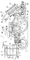
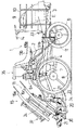
まず、八条植えの乗用田植機について図1、図2より全体構成から説明する。
オペレータ等が搭乗する走行機体1の、車体フレーム3の前部上方にエンジンEを搭載し、該エンジンEの動力をミッションケース4に伝え、該ミッションケース4よりフロントアクスルケース5及びリヤアクスルケース7に動力を伝えて、前輪6及び後輪8をそれぞれ駆動する構成としている。
そして、前記エンジンEを覆うボンネット9の周りに前部車体カバー12が形成され、該前部車体カバー12の側部に予備苗載台10・10を配設し、前記ミッションケース4等を後部車体カバー2によって覆い、該後部車体カバー2中央上部に運転席13を取り付け、該運転席13の前方の前記ボンネット9後部に操向ハンドル14を配設している。また、前記後輪8の外側には外側補助車輪150・150を装着可能としている。
【0010】
また、植付け部15は苗載台16や複数の植付け爪17等から構成されており、前高後低に配設した苗載台16を下部レール及びガイドレール19を介して植付けケース20に左右往復摺動自在に支持させると共に、一方向に等速回転するロータリーケース21を前記植付けケース20に回転自在にさせ、該ロータリーケース21の回転軸芯を中心にして対称位置に一対の爪ケース22・22を配設し、該爪ケース22・22の先端に植付け爪17・17を配置している。
【0011】
また、前記植付けケース20の前部はローリング支点軸23を介して支持フレーム24に支持され、トップリンク25及びロワーリンク26等のリンク機構27を介して走行機体1後部に装着されている。前記植付け部15は昇降シリンダ28の伸縮によって昇降される。そして、前記苗載台16から一株分の苗を植付け爪17によって取り出し、連続的に苗植え作業を行う構成としている。
【0012】
また、前記運転席13等が設置された運転部には走行変速レバー29、植付け昇降兼作業走行変速用副変速レバー30、植付け感度調節レバー31、主クラッチペダル32、左右ブレーキペダル33・33、サイドクラッチペダル39・39が配設され、前記植付け部15下部には均平用センタフロート34、均平用サイドフロート35が配設され、前記運転席13後方には八条用の施肥部36が配設されている。
【0013】
前記苗載台16は、図1、図2に示すように、左右最外端の各二条分の苗載台を分割して分割苗載台16a・16aとし、機体中央の四条を固定側苗載台16bとし、該固定側苗載台16bの左右端部に並行折畳み機構37を設け、前記分割苗載台16a・16aと固定側苗載台16bとを並行折畳み機構37を介して連結し、固定側苗載台16bの上方に略平行に分割苗載台16a・16aを折畳み可能に構成している。
【0014】
次に、前記前部車体カバー12と後部車体カバー2の形状に付いて説明する。
前記前部車体カバー12と後部車体カバー2とは、各々中空ブロー成形によって一体成形されている。図1〜図3に示すように、前記前部カバー12は、左右中央部にボンネット9の配置される開口部が設けられ、その左右両側にフロア12a・12aが形成されている。該フロア12aは前後途中部より後方側に傾斜面が形成され、フロア12a後部をボンネット9後端部の直後方位置まで延出している。前記フロア12aの上面にはゴム製のプレートが貼設されている。
【0015】
また、前記後部車体カバー2は、ボンネット9後部より、車体フレーム3の後端部まで延設されている。該後部車体カバー2は、前部は平状にフロア2aが形成され、後部車体カバー2後部は上方に一段高く構成され、運転席載置部2bと作業用ステップ2cとが成形されている。該フロア2aの上面にはゴム製のプレートが貼設されている。
【0016】
更に、前記運転席載置部2bの左側には走行変速レバー29のガイド溝2hが開口され、運転席載置部2bの右側に昇降兼作業走行変速用副変速レバー30のガイド溝2i等が開口されている。前記後部車体カバー2のフロア2a後端部から運転席載置部2b前部若しくは作業用ステップ2c前部にかけて傾斜状に前部壁2dが成形されている。
【0017】
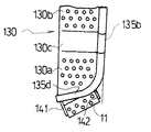
また、前記後部車体カバー2の左右両側に延長ステップ130が配設されている。該延長ステップ130は、後部車体カバー2の側面形状に沿って前後方向に長く形成されている。また、該延長ステップ130は、後部車体カバー2と同様に、前後中央部より前方と後方とを段差状に形成して形状を合わせている。
即ち、該延長ステップ130の前部は、フロア2a面と同一平面である拡大側フロア130aが成形され、拡大側フロア130a前部をフロア2aの前後途中位置まで伸延させている。また、前記延長ステップ130後部は、作業用ステップ2c面と同一平面とする拡大側ステップ130bが形成されている。該拡大側ステップ130b後部は、作業用ステップ2c後端部よりさらに後方に伸延されている。更に、前記延長ステップ130の段差が成形される前後中央位置は、後部車体カバー2の前部壁2dに沿うように、傾斜壁130cが成形されている。更に、前記拡大側フロア130aと拡大側ステップ130bとの上面には、滑り止め用の凸部が突出されている。
【0018】
前記延長ステップ130は、車体フレーム3側に固設されるステー132・133に支持されている。前記ステー132は、後輪8上前方に横設され、ステー132端部が後輪8より側方に突出され、該ステー132端部に拡大側ステップ130b下面が載置されている。前記ステー133は、前輪6と後輪8との間位置に横設され、ステー133端部を側上方に突出し、該ステー133の上部に傾斜壁130c下面が固設され、ステー132・133によって延長ステップ130が支持されている。従って、前述したように、前記後部車体カバー2と、左右両側の延長ステップ130・130とが車体フレーム3側に個別に支持されている。
【0019】
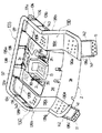
また、前記延長ステップ130の外側周囲に、本発明のガイドフレーム135が配置されてフレーム枠を形成すると共に、該ガイドフレーム135を用いて左右の延長ステップ130・130とを一体的に連結する構成している。
【0020】
該ガイドフレーム135は、リアフレーム135aとサイドフレーム135b・135bからなり、パイプより構成したこのリアフレーム135aとサイドフレーム135b・135bを連結して、平面視略門型に一体的に成形し、該ガイドフレーム135の開放面を前方に向け、ガイドフレーム135の左右側部の内側に延長ステップ130・130を固設している。
但し、ガイドフレーム135は一本のパイプフレームで構成することもできる。
【0021】
図1、図3に示すように、前記リアフレーム135aは平面視コ字状に構成して、該リアフレーム135bの左右中央部より下方に支持フレーム138・138が垂設されて、該支持フレーム138・138の下端は前記車体フレーム3後部に固定される。該リアフレーム135b下部の支持フレーム138・138両側に固定板137が固設され、該リアフレーム135bの前端の下面には固定板134が垂設されて、該固定板137・134の下部に後補強フレーム131aが水平に固定される。こうして、リアフレーム135aは延長ステップ130・130の後上方に平行に配置される。
【0022】
前記サイドフレーム135b・135bは左右対称に構成されるので、一方について説明する。該サイドフレーム135bの前部135dは、前記拡大側フロア130aの形状に合わせて平面視「く」字状に形成され、該前部135dの前端部はフロア2a側部の前後途中位置に当接するように配設される。また、前記サイドフレーム135bの中途部は側面視「へ」字状に曲げられて、前記傾斜壁130c側部に沿った形状としている。該サイドフレーム135bの後端を、延長ステップ130と平行に構成して前記リアフレーム135aに連結されて一体的に構成され、該サイドフレーム135bの後端下面に固定板136が垂設され、その前方位置に支持軸143が上下方向に垂設されて、該固定板136と支持軸143下部に前補強フレーム131bが水平に固設され、サイドフレーム135bとリアフレーム135a、及び、後補強フレーム131aと前補強フレーム131bがそれぞれ同一軸心上に連結する構成としている。
【0023】
そして、該後補強フレーム131aと前補強フレーム131bは前記拡大側ステップ130bの外側の側部と後部とに沿って配置され、該補強フレーム131とガイドフレーム135とによって、拡大側ステップ130bのフレーム枠が形成され、拡大側ステップ130bの剛性が高められている。
【0024】
従って、前記固定板136・136と支持軸143・143とによって、ガイドフレーム135と拡大側ステップ130b・130bとが連結され、左右両側の延長ステップ130・130が一体的に固設されるのである。更に、サイドフレーム135bとリアフレーム135aを連結することによって、ガイドフレーム135が固定板136、支持軸143、固定板137、支持フレーム138を介して左右の前記延長ステップ130・130と車体フレーム3に支持され、剛性が高められるのである。そして、前記サイドフレーム135bは拡大側ステップ130b面より上方に配設されているので、オペレータが、拡大側フロア130aやフロア2aに乗り降りする際に手摺りとして使用することができる。
【0025】
次に、前記後部車体カバー2のフロア2a、若しくは延長ステップ130の拡大側フロア130aへ乗り降りするための補助ステップ11の配置構成について説明する。
図3、図4、図6に示すように、前記サイドフレーム135bの前部135dの、左右方向のフレームから連結板141・142を垂設し、該連結板141と連結板142下端との間に補助ステップ11が固設されている。また、図6の側面図において図示する如く、前記補助ステップ11後部の内側には補助板144が固設され、該補助板144を後上方に延出し、拡大側フロア130a下面に固設したブラケット139に固設され、補助ステップ11の補強を行っている。
【0026】
更に、該補助ステップ11の最外側は、図4に示す平面視のように、延長ステップ130の最外側の延長線上より内側に配置されている。よって、前記補助ステップ11は、機体の左右幅内に収められ、また、補助ステップ11を前後斜めに配したことで、ステップの面積を大きくすることができ、機体の側方より搭乗するオペレータにとって、足をかけ易くしている。
【0027】
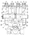
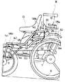
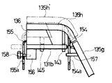
また、図5、図6に示すように、前記後部車体カバー2後方で、左右の延長ステップ130・130の間位置に空気圧送型の施肥部36を配設することができるようにしており、前記リアフレーム135a及び後補強フレーム131aを外して、後部車体カバー2後方の車体フレーム3より支持フレーム60を立設して、該支持フレーム60上部に施肥部36を固設する構成としている。
【0028】
該施肥部36は、植付け条数に合わせた数の施肥タンク61と該施肥タンク61に連結される施肥ホース62が配置され、更に圧縮エアを吐出するための筒状のエアタンク63、該エアタンク63の右側端部に配してエアを圧送するためのブロワ64等が配設される。前記エアタンク63は左右方向に横設され、ガイドフレーム135と同一高さに配置され、左右外側の施肥タンク61下方まで延出し、各施肥ホース62に圧縮エアを吐出できるようにしている。前記施肥ホース62下端は、均平用センタフロート34や均平用サイドフロート35・35・・・に固設し、施肥ホース62下端を圃場内に突入させている。
更に、前記ブロワ64は内側端部が回動自在に枢支され、機体の収納時や移動時に左右内側にブロワ64を回動して、機体の左右幅が狭められている。
【0029】
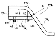
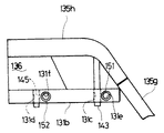
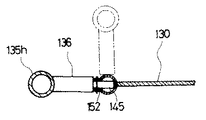
更に、前記右側(本実施例では右側でありブロワ64の配設した側)のサイドフレーム135bは後部の傾斜部分(ラインb)で前後に分割可能に構成して、取り外し可能に構成している。
即ち、図7〜図9に示すように、前記サイドフレーム135bは前方の固定側フレーム135gと、ラインbより後方の取り外しフレーム135hとに分割され、該取り外しフレーム135h下面には、前述した支持軸143と固定板136が固定され、該支持軸143下部にピン孔143aが構成され、固定板136下面の前後中央位置にはネジ軸145が下方に突出されている。
一方、前記前補強フレーム131bの前端は、固定側フレーム135gに溶接等で固設され、前記支持軸143とネジ軸145との位置に合わせて上下方向に孔131c・131bを開口して、支持軸143とネジ軸145を挿入し、支持軸143は抜け止め用のピンで固定し、ネジ軸145はナット148で固設するようにしている。
【0030】
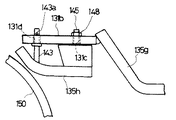
このような構成において、ブロワ64を内側に回動させて収納するときには、前記支持軸143下端部の抜け止め用のピンを抜き取り、ネジ軸145下端部のナット148を外し、前記取り外しフレーム135hを上方に持ち上げると、支持軸143とネジ軸145とが前補強フレーム131bより抜脱され、取り外しフレーム135hが取り外される。
【0031】
そして、図9に示すように、前記取り外しフレーム135hを前後及び上下逆向きとして、前補強フレーム131b下方より、前記支持軸143を後方の孔131d内に挿入し、前記ネジ軸145を前方の孔131c下方より挿入し、支持軸143の上端部を抜け止め用のピンで抜け止めし、ネジ軸145上端をナット148で固定する。
よって、機体の移動時や格納時に前記取り外しフレーム135hが前補強フレーム131b下方に位置し、ブロワ64をガイドフレーム135と干渉させることなく、内側に回動させて、機体の左右幅を狭めることができる。
また、前記取り外しフレーム135hを下側に配置したときには、その後端は「へ」字状にまげられているので後輪8と干渉せず、後輪9の外側に外側補助輪150を固設しても、外側補助輪150と取り外しフレーム135hとが干渉することがない。
【0032】
また、前記取り外しフレーム135hを用いて、延長ステップ130の幅をさらに側方に広げる構成にすることもできる。図10、図11に示すように、前記前補強フレーム131bの側面に、前記孔131c・131dの位置と前または後にズラせて、間隔は同じとして左右方向に孔131e・131fを開口し、該孔131e・131fにそれぞれボス151・ボス152を嵌合している。
【0033】
そして、取り外した前記取り外しフレーム135hの支持軸143とネジ軸145とを外側から水平方向にボス151・152に挿入し、抜け止め用のピンとナット148で固定することで、前記延長ステップ130より外側に水平方向に延長して取り外しフレーム135hが配され、荷物等を載置するスペースを設けることができる。
【0034】
次に、前記取り外しフレーム135hの支持構成の別実施例について、図12、図13を用いて説明する。
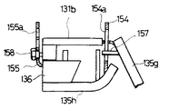
前述した第一実施例と同様に、取り外しフレーム135hは、下方に支持軸143とネジ軸145とを突出し、該支持軸143とネジ軸145とが前補強フレーム131b内に挿入され支持されている。さらにこの形態においては、取り外しフレーム135hを下方に回動自在に支持している。前記前補強フレーム131b後部下部に固定部156が固設されている。該固定部156後面には、固定ピン158が挿入されるピン孔が開口されている。該固定ピン158は、軸径の異なる段差状に形成され、端部にノブが固設されている。また、前記固定側フレーム135g後部に、水平後方に支点軸157が突出されている。
【0035】
一方、前記取り外しフレーム135hの前部より下方に、回動アーム154を固設し、該回動アーム154を下方に突出している。該回動アーム154には、上下方向に長径を有する長孔154aが開口され、該長孔154a内に、前記支持軸157が遊嵌されている。
【0036】
更に、前記固定板136後部に係合アーム155が固設され、該係合アーム155を下方に突出し、固定部156後面の後方位置まで延出されている。前記係合アーム155には、上下方向に複数個の孔と、該孔を溝によって連通させた形状の長孔155aが開口されている。該長孔155a内には、固定部156に挿入される固定ピン158の段差部が遊嵌されている。前記固定ピン158を固定部156に深く挿入すると、長孔155aの孔内に固定ピン158が係合されている。固定ピン158を浅く挿入した状態にすると、固定ピン158と長孔155aの孔との係合が外れ、取り外しフレーム135hを上下動させることができる。
【0037】
このように構成したことによって、通常の作業時においては、前記前補強フレーム131b上方に取り外しフレーム135hを配設し、該取り外しフレーム135hを機体への昇降時の把手として使用したり、延長ステップ130上で作業するオペレータの足元を保護するようにしている。
【0038】
そして、田植機の作業を行わない移動時や格納時においてブロワ64を機体内側に収納させる際には、先ず、固定ピン158を後ろ側に引いて、固定ピン158と係合アーム155との係合を外す。この次に、取り外しフレーム135hを上方に持ち上げると、取り外しフレーム135h前部の回動アーム154が支点軸157に案内され、取り外しフレーム135h後部の係合アーム155が固定ピン158に案内されながら、取り外しフレーム135hが上方に持ち上げられる。該取り外しフレーム135hが図12の二点鎖線の135h’に示すように位置すると、支持軸143・145が前補強フレーム131bより抜脱される。
【0039】
そして、取り外しフレーム135hを支点軸157と固定ピン158とを中心に下方に回動させている。前記延長ステップ130の下方に回動した取り外しフレーム135hを上方に持ち上げ、係合アーム155の長孔155a内の適所位置と固定ピン158との位置を一致させている。
そして、固定ピン158を深く差し込んで、固定ピン158と係合アーム155とを係合させて、取り外しフレーム135hを前補強フレーム131bの下方位置に固定している。よって、前記固定ピン158の操作のみで取り外しフレーム135hが下方に回動され、延長ステップ130上部が開放され、ブロワ64を機体内側に収納することができる。
【0040】
【発明の効果】
本発明は以上の如く構成したので、次のような効果を奏するのである。
請求項1においては、田植機の走行機体後部に多条植え用の植付部を付設し、運転席13周りのフロアやステップを構成する後部車体カバー2を車体フレーム3上に載置した構成において、該後部車体カバー2の左右両側に延長ステップ130を配し、該延長ステップ130の周囲を囲むガイドフレーム135を設け、該ガイドフレーム135を、リアフレーム135aとサイドフレーム135b・135bにより構成し、該リアフレーム135aと、該サイドフレーム135b・135bの後部を取り外し可能に構成し、該取り外した位置に、作業機を取付可能に構成したので、左右両側の延長ステップを固設した平面視略門型のガイドフレームの後部を、延長ステップの上方位置に配したことで、延長ステップ後部で、苗マットの供給作業等を行っているオペレータの足元が保護され、延長ステップ上で作業するオペレータにさらなる安心感がもたらせられる。
また、該サイドフレームの後部を取り外し可能にし、取り外しすることで、更に大きな作業機を配したり、サイドフレームより外側に突出した作業機を折り畳んで収納する際に、干渉することなくスムーズに収納することができる。
【0041】
請求項2においては、請求項1記載の田植機のステップ構造において、該作業機を、植付け条数に合わせた施肥タンク61とブロワ64より構成される施肥部36としたので、空気圧送型の施肥機を搭載した場合に、サイドフレームより外側に突出していた空気を施肥機に圧送するブロワを収納することができる。
【0042】
請求項3においては、請求項1記載の田植機のステップ構造において、後部車体カバー2と延長ステップ130とガイドフレーム135とを一体的に構成し、前記延長ステップ130に突設したステー132・133を、車体フレーム3側に載置固設したので、後部車体カバーの左右両側に配した延長ステップと、後部車体カバーとが車体フレームに支持されており、平面視略門型のガイドフレームによって、左右の延長ステップを後部車体カバーを跨いで左右両側の延長ステップを固設しており、左右の延長ステップと後部車体カバーとに一体感を生じ、延長ステップ上で作業するオペレータが安心して苗マットの供給作業等を行うことができる。
【0043】
請求項4においては、請求項1記載の田植機のステップ構造において、該ガイドフレーム135の前後中途部を延長ステップ130より上方に配置して把手としたので、平面視略門型のガイドフレームの前後途中部を延長ステップより上方に配して、その部分を機体への乗り降りにおける把手として使用することができ、乗降時のオペレータの負担を軽減することができる。
【0044】
請求項5においては、請求項1記載の田植機のステップ構造において、前記サイドフレーム135bは前方の固定側フレーム135gと、後方の取り外しフレーム135hとに分割され、該取り外しフレーム135hは、取り外し後に上下方向の取付孔に下方から取付け可能としたので、サイドフレーム後部を延長ステップ上面に配置したり、延長ステップ下面に配置することができる。延長ステップ下面にサイドフレーム後部を配した状態にすることで、機体後部に配した作業機を折り畳み、機体の左右幅を狭めた状態にするこができ、機体を移動したり格納することが出来るのである。
【0045】
請求項6においては、請求項1記載の田植機のステップ構造において、前記サイドフレーム135bは前方の固定側フレーム135gと、後方の取り外しフレーム135hとに分割され、該取り外しフレーム135hは、取り外し後に左右方向の取付孔に側方から取付け可能としたので、サイドフレーム後部を延長ステップに沿って水平方向に配置することができ、延長ステップの横幅をさらに大きくすることができ、荷物等を載置する空間を広くすることが出来るのである。
【0046】
請求項7においては、請求項1記載の田植機のステップ構造において、前記延長ステップ130の前部より前下方に乗降用の補助ステップ11を延設したので、該補助ステップを延長ステップに一体的に固設したことによって、延長ステップを取り外すと同時に、補助ステップも取り外すことができる。よって、メンテナンス作業時に、個別に補助ステップを取り外す必要がないので、組立を簡略化した構成となっている。
【0047】
請求項8においては、請求項1記載の田植機のステップ構造において、該延長ステップ130前部より前下方に配した補助ステップ11を前方外側向きに配し、補助ステップ11の外側端部を延長ステップ130の外側面より内側に配置したので、機体の左右幅が広がることをできるだけ抑えた構成にして、補助ステップを前方外側向きに傾斜させて配しており、ステップとして使用するための十分な面積があるので、側方より乗降するオペレータによって、足をかけやすい構成とすることができたものである。
【図面の簡単な説明】
【図1】 本発明の車体カバーを有する田植機の全体右側面図である。
【図2】 同じく平面図である。
【図3】 本発明の延長ステップを装着した車体カバーの斜視図である。
【図4】 延長ステップに装着した補助ステップの配置を示す平面図である。
【図5】 走行機体後部に施肥機を搭載した田植機の全体左側面図である。
【図6】 本発明の分割した延長ステップを配した作業車の部分側面図である。
【図7】 分割可能な前部フレームを配した作業車の部分側面図である。
【図8】 取り外しフレームの支持構成を差し込み式にした側面図である。
【図9】 取り外しフレームの支持構成を示す側面図である。
【図10】 差し込み式にした取り外しフレームの別の支持構成を示す側面図である。
【図11】 取り外しフレームの別の支持構成を示す正面断面図である。
【図12】 取り外しフレームの別形態の支持構成を示す側面である。
【図13】 同じく取り外しフレームの支持構成を示す側面図である。
【符号の説明】
1 走行機体
2 後部車体カバー
2a フロア
2c ステップ
3 車体フレーム
11 補助ステップ
12 前部車体カバー
12c 膨出部
12e 合わせ孔
12d エア吹き込み口
12m 凸部
12p 補強部
13 運転席
15 植付け部
36 施肥部
63 エアタンク
64 ブロア
130 延長ステップ
135 ガイドフレーム
135a リアフレーム
135b サイドフレーム
135f 取り外しフレーム
143・145 支持軸
131c・131d 孔
131e・131f 孔
[0001]
BACKGROUND OF THE INVENTION
  The present invention relates to a configuration in which a step is provided on the side of a body cover around a driver's seat of a multi-row rice transplanter such as 8-row planting or 10-row planting to expand a work space.
[0002]
[Prior art]
  2. Description of the Related Art Conventionally, a rice transplanter in which a planting unit is attached to the rear of a traveling machine body, a pneumatic feeding fertilizer is mounted on the rear part of the traveling machine body, and seedlings are planted on a farm field and at the same time the fertilizer is pumped.
  Further, a driver's seat is placed on the center of the body cover of the rice transplanter, a floor is formed in front of the driver's seat, and a working step is formed in the rear of the driver's seat that is one step higher than the floor. . Using the work step as a step, fertilizer was replenished to a fertilizer disposed at the rear of the traveling vehicle, or a seedling mat was spliced to a seedling stage.
[0003]
[Problems to be solved by the invention]
  However, since the blower for pumping the fertilizer was arranged at the end of the fertilizer application and protruded, there was a possibility that it would come into contact with an obstacle during movement, and a configuration for storing it on the machine body side was desired. . Further, in the case of the rice transplanter for 8 or 10 strips, the strips at both ends are far from each other, and it is impossible to replenish the seedling mats from the working steps of the body cover to the seedling platforms at the left and right ends. Burdened the person.
[0004]
[Means for Solving the Problems]
  The problems to be solved by the present invention are as described above. Next, means for solving the problems will be described.
  In Claim 1, the planting part for multi-row planting is attached to the traveling machine body rear part of a rice transplanter, and the rear body cover 2 which comprises the floor and step around the driver's seat 13 is mounted on the body frame 3 , The extension step 130 is arranged on both left and right sides of the rear body cover 2, and a guide frame 135 surrounding the extension step 130 is provided.The guide frame 135 is composed of a rear frame 135a and side frames 135b and 135b, and the rear frame 135a and rear portions of the side frames 135b and 135b are configured to be removable, and a work machine is attached to the removed position. PossibleIt is composed.
  In claim 2,The step structure of the rice transplanter of Claim 1 WHEREIN: This working machine was made into the fertilizer part 36 comprised from the fertilization tank 61 and the blower 64 according to the number of planting strips.Is.
[0005]
  In claim 3,2. The step structure of a rice transplanter according to claim 1, wherein the rear body cover 2, the extension step 130, and the guide frame 135 are integrally formed, and the stays 132 and 133 projecting from the extension step 130 are connected to the body frame 3 side. Placed and fixedIs.
  In claim 4,The step structure of the rice transplanter according to claim 1, wherein the guide frame 135 has a front and rear halfway portion disposed above the extension step 130 to be a handle.It is.
[0006]
  In claim 5,The step structure of the rice transplanter according to claim 1, wherein the side frame 135b is divided into a front fixed side frame 135g and a rear removal frame 135h, and the removal frame 135h is lowered to a vertical mounting hole after removal. It can be installed fromIs.
  In claim 6,2. The step structure of a rice transplanter according to claim 1, wherein the side frame 135b is divided into a front fixed side frame 135g and a rear removal frame 135h, and the removal frame 135h is formed on the side of the left and right mounting holes after removal. It was possible to install fromIs.
[0007]
  In claim 7,In the step structure of the rice transplanter of Claim 1,The auxiliary step 11 for getting on and off is extended from the front part of the extension step 130 to the front lower side.
  In claim 8,In the step structure of the rice transplanter of Claim 1,The auxiliary step 11 arranged forward and downward from the front portion of the extension step 130 is arranged in the front outer direction, and the outer end portion of the auxiliary step 11 is arranged inside the outer surface of the extension step 130.
[0008]
DETAILED DESCRIPTION OF THE INVENTION
  Next, an embodiment of the present invention will be described.
  1 is an overall right side view of a rice transplanter having a vehicle body cover according to the present invention, FIG. 2 is a plan view of the same, FIG. 3 is a perspective view of a vehicle body cover equipped with the extension step of the present invention, and FIG. FIG. 5 is a left side view of the whole rice transplanter equipped with a fertilizer applicator at the rear of the traveling vehicle, FIG. 6 is a partial side view of the work vehicle provided with the divided extension steps of the present invention, and FIG. 7 is a partial side view of a work vehicle provided with a split front frame, FIG. 8 is a side view in which the support structure of the removal frame is inserted, FIG. 9 is a side view showing the support structure of the removal frame, and FIG. FIG. 11 is a front sectional view showing another support structure of the removal frame, and FIG. 12 is a side view showing another support structure of the removal frame. Cover the back To a side sectional view, FIG. 13 is a side view also showing a supporting structure of the removable frame.
[0009]
  First, an eight-row riding rice transplanter will be described from FIG. 1 and FIG.
  An engine E is mounted above the front part of the vehicle body frame 3 of the traveling body 1 on which an operator or the like is boarded, and the power of the engine E is transmitted to the transmission case 4 from the transmission case 4 to the front axle case 5 and the rear axle case 7. Power is transmitted to drive the front wheel 6 and the rear wheel 8 respectively.
  A front vehicle body cover 12 is formed around the bonnet 9 covering the engine E, a preliminary seedling stage 10 is disposed on the side of the front vehicle body cover 12, and the transmission case 4 and the like are arranged at the rear. Covered by the vehicle body cover 2, a driver's seat 13 is attached to the center upper portion of the rear vehicle body cover 2, and a steering handle 14 is disposed at the rear of the bonnet 9 in front of the driver's seat 13. Further, outside auxiliary wheels 150 and 150 can be attached to the outside of the rear wheel 8.
[0010]
  The planting unit 15 is composed of a seedling mounting table 16 and a plurality of planting claws 17. The seedling mounting table 16 disposed at the front height and the lower level is placed on the planting case 20 via the lower rail and the guide rail 19. A rotary case 21 that is supported so as to be slidable back and forth and that rotates at a constant speed in one direction is rotated by the planting case 20, and a pair of claw cases 22 are symmetrically positioned about the rotation axis of the rotary case 21. 22 is arranged, and planting claws 17 and 17 are arranged at the tips of the claw cases 22 and 22.
[0011]
  The front portion of the planting case 20 is supported by a support frame 24 via a rolling fulcrum shaft 23 and attached to the rear portion of the traveling machine body 1 via a link mechanism 27 such as a top link 25 and a lower link 26. The planting part 15 is moved up and down by the expansion and contraction of the lifting cylinder 28. And it is set as the structure which takes out the seedling for one stock from the said seedling mounting stand 16 with the planting nail | claw 17, and performs a seedling planting operation | work continuously.
[0012]
  In addition, the driving section in which the driver's seat 13 and the like are installed has a traveling speed change lever 29, a planting elevating / lowering and working speed changing sub-shift lever 30, a planting sensitivity adjusting lever 31, a main clutch pedal 32, left and right brake pedals 33 and 33, Side clutch pedals 39 and 39 are disposed, a leveling center float 34 and leveling side float 35 are disposed at the bottom of the planting portion 15, and an eight-row fertilizer 36 is disposed behind the driver seat 13. It is arranged.
[0013]
  As shown in FIGS. 1 and 2, the seedling stage 16 divides the seedling stage for each of the two outermost ends into split seedling stages 16a and 16a. A parallel folding mechanism 37 is provided at the left and right ends of the stationary seedling mounting base 16b, and the divided seedling mounting bases 16a and 16a and the stationary seedling mounting base 16b are connected via the parallel folding mechanism 37. The split seedling stage 16a, 16a is configured to be foldable substantially parallel above the fixed side seedling stage 16b.
[0014]
  Next, the shapes of the front body cover 12 and the rear body cover 2 will be described.
  The front vehicle body cover 12 and the rear vehicle body cover 2 are each integrally formed by hollow blow molding. As shown in FIGS. 1 to 3, the front cover 12 is provided with an opening in which the bonnet 9 is disposed at the left and right central portions, and floors 12 a and 12 a are formed on both left and right sides thereof. The floor 12a is formed with an inclined surface on the rear side from the middle part in the front-rear direction, and the rear part of the floor 12a extends to a position just behind the rear end part of the bonnet 9. A rubber plate is stuck on the upper surface of the floor 12a.
[0015]
  The rear body cover 2 extends from the rear part of the bonnet 9 to the rear end part of the body frame 3. The rear body cover 2 has a flat floor 2a at the front, a rear portion of the rear body cover 2 is formed one step higher, and a driver seat mounting portion 2b and a work step 2c are formed. A rubber plate is stuck on the upper surface of the floor 2a.
[0016]
  Further, a guide groove 2h of the traveling speed change lever 29 is opened on the left side of the driver seat mounting portion 2b, and a guide groove 2i of the sub-shift lever 30 for elevating / working traveling speed change is provided on the right side of the driver seat mounting portion 2b. It is open. A front wall 2d is formed in an inclined shape from the rear end of the floor 2a of the rear body cover 2 to the front of the driver seat mounting portion 2b or the front of the work step 2c.
[0017]
  Further, extension steps 130 are disposed on the left and right sides of the rear body cover 2. The extension step 130 is formed long in the front-rear direction along the side surface shape of the rear vehicle body cover 2. Further, like the rear body cover 2, the extension step 130 is formed in a step shape from the front and rear center part to form a step shape.
  That is, the front side of the extension step 130 is formed with an enlarged floor 130a that is flush with the surface of the floor 2a, and the front part of the enlarged side floor 130a is extended to the midway position before and after the floor 2a. Further, the rear side of the extension step 130 is formed with an enlarged side step 130b that is flush with the work step 2c surface. The rear part of the enlargement side step 130b is extended further rearward than the rear end part of the work step 2c. Further, an inclined wall 130c is formed so that the front and rear center position where the step of the extension step 130 is formed is along the front wall 2d of the rear body cover 2. Further, non-slip convex portions protrude from the upper surfaces of the expansion side floor 130a and the expansion side step 130b.
[0018]
  The extension step 130 is supported by stays 132 and 133 fixed to the vehicle body frame 3 side. The stay 132 is horizontally provided on the front side of the rear wheel 8, the end of the stay 132 protrudes laterally from the rear wheel 8, and the lower surface of the enlarged side step 130 b is placed on the end of the stay 132. The stay 133 is horizontally provided at a position between the front wheel 6 and the rear wheel 8, the end of the stay 133 protrudes upward in the side, and the lower surface of the inclined wall 130 c is fixed to the upper portion of the stay 133. An extension step 130 is supported. Therefore, as described above, the rear body cover 2 and the left and right extension steps 130 and 130 are individually supported on the body frame 3 side.
[0019]
  Further, the guide frame 135 of the present invention is arranged around the outside of the extension step 130 to form a frame, and the left and right extension steps 130 and 130 are integrally connected using the guide frame 135. is doing.
[0020]
  The guide frame 135 includes a rear frame 135a and side frames 135b and 135b. The rear frame 135a and the side frames 135b and 135b, which are formed of pipes, are connected to each other, and are integrally formed in a gate shape in plan view. Extension steps 130 and 130 are fixed inside the left and right side portions of the guide frame 135 with the open surface of the guide frame 135 facing forward.
  However, the guide frame 135 can also be composed of a single pipe frame.
[0021]
  As shown in FIGS. 1 and 3, the rear frame 135a is formed in a U-shape in plan view, and support frames 138 and 138 are provided below the center of the left and right sides of the rear frame 135b. The lower ends of 138 and 138 are fixed to the rear portion of the vehicle body frame 3. Fixing plates 137 are fixed to both sides of the support frames 138 and 138 below the rear frame 135b, and a fixing plate 134 is suspended from the lower surface of the front end of the rear frame 135b. The reinforcing frame 131a is fixed horizontally. In this way, the rear frame 135a is arranged parallel to the upper rear of the extension steps 130 and 130.
[0022]
  Since the side frames 135b and 135b are configured symmetrically, only one will be described. The front portion 135d of the side frame 135b is formed in a “<” shape in plan view in accordance with the shape of the enlarged-side floor 130a, and the front end portion of the front portion 135d abuts the midway position of the side portion of the floor 2a. It is arranged as follows. Further, the middle part of the side frame 135b is bent in a “h” shape when viewed from the side, and has a shape along the side of the inclined wall 130c. The rear end of the side frame 135b is configured in parallel with the extension step 130 and connected to the rear frame 135a, and is integrally formed. A fixing plate 136 is vertically provided on the lower surface of the rear end of the side frame 135b. A support shaft 143 is vertically suspended at a front position, a front reinforcing frame 131b is horizontally fixed below the fixing plate 136 and the supporting shaft 143, a side frame 135b, a rear frame 135a, and a rear reinforcing frame 131a. And the front reinforcing frame 131b are connected to each other on the same axis.
[0023]
  The rear reinforcing frame 131a and the front reinforcing frame 131b are disposed along the outer side and the rear part of the enlarged side step 130b, and the reinforcing frame 131 and the guide frame 135 define the frame frame of the enlarged side step 130b. And the rigidity of the enlargement side step 130b is enhanced.
[0024]
  Therefore, the guide plate 135 and the expansion side steps 130b and 130b are connected by the fixing plates 136 and 136 and the support shafts 143 and 143, and the extension steps 130 and 130 on both the left and right sides are integrally fixed. . Further, by connecting the side frame 135b and the rear frame 135a, the guide frame 135 is connected to the left and right extension steps 130 and 130 and the vehicle body frame 3 via the fixed plate 136, the support shaft 143, the fixed plate 137, and the support frame 138. It is supported and the rigidity is increased. And since the said side frame 135b is arrange | positioned above the expansion side step 130b surface, when an operator gets on and off the expansion side floor 130a or the floor 2a, it can be used as a handrail.
[0025]
  Next, the arrangement configuration of the auxiliary step 11 for getting on and off the floor 2a of the rear body cover 2 or the expansion side floor 130a of the extension step 130 will be described.
  As shown in FIGS. 3, 4, and 6, connecting plates 141 and 142 are suspended from the left and right frames of the front portion 135 d of the side frame 135 b, and between the connecting plate 141 and the lower end of the connecting plate 142. The auxiliary step 11 is fixedly installed. Also,As illustrated in the side view of FIG.An auxiliary plate 144 is fixed inside the rear portion of the auxiliary step 11, and the auxiliary plate 144 extends rearward and upward and is fixed to a bracket 139 fixed to the lower surface of the enlarged floor 130a. Is going.
[0026]
  Further, the outermost side of the auxiliary step 11 is disposed on the inner side of the outermost extension line of the extension step 130 as seen in a plan view shown in FIG. Therefore, the auxiliary step 11 is accommodated within the left and right width of the aircraft, and the auxiliary step 11 is arranged obliquely in the front-rear direction so that the area of the step can be increased. , Make it easy to put your feet.
[0027]
  Further, as shown in FIGS. 5 and 6, an air-feeding fertilizer 36 can be disposed between the left and right extension steps 130 and 130 at the rear of the rear body cover 2. The rear frame 135a and the rear reinforcing frame 131a are removed, a support frame 60 is erected from the vehicle body frame 3 behind the rear vehicle body cover 2, and the fertilizer 36 is fixedly provided on the support frame 60.
[0028]
  The fertilizer 36 is provided with fertilizer tanks 61 and fertilizer hoses 62 connected to the fertilizer tanks 61 in accordance with the number of planting lines, a cylindrical air tank 63 for discharging compressed air, and the air tank 63 A blower 64 or the like is disposed at the right end of the air supply unit for pressure-feeding air. The air tank 63 is horizontally provided in the left-right direction, and is disposed at the same height as the guide frame 135. The air tank 63 extends below the left and right fertilization tanks 61 so that compressed air can be discharged to each fertilization hose 62. The lower end of the fertilization hose 62 is fixed to the leveling center float 34 and the leveling side floats 35, 35..., And the lower end of the fertilization hose 62 enters the field.
  Further, the blower 64 is pivotally supported at its inner end so that the blower 64 is pivoted inwardly at the time of storing and moving the aircraft, thereby narrowing the lateral width of the aircraft.
[0029]
  Further, the side frame 135b on the right side (the right side in this embodiment and the side on which the blower 64 is disposed) is configured to be detachable in the front and rear at the rear inclined portion (line b) and configured to be removable. .
  That is, as shown in FIGS. 7 to 9, the side frame 135b is divided into a front fixed side frame 135g and a removal frame 135h behind the line b, and the lower surface of the removal frame 135h has the above-described support shaft. 143 and the fixing plate 136 are fixed, a pin hole 143a is formed at the lower portion of the support shaft 143, and a screw shaft 145 protrudes downward at the front and rear center position of the lower surface of the fixing plate 136.
  On the other hand, the front end of the front reinforcing frame 131b is fixed to the fixed side frame 135g by welding or the like, and the holes 131c and 131b are opened in the vertical direction in accordance with the positions of the support shaft 143 and the screw shaft 145 to support it. The shaft 143 and the screw shaft 145 are inserted, the support shaft 143 is fixed with a pin for preventing the removal, and the screw shaft 145 is fixed with a nut 148.
[0030]
  In such a configuration, when the blower 64 is pivoted inwardly and stored, the retaining pin at the lower end of the support shaft 143 is removed, the nut 148 at the lower end of the screw shaft 145 is removed, and the removal frame 135h is removed. When lifted upward, the support shaft 143 and the screw shaft 145 are removed from the front reinforcing frame 131b, and the removal frame 135h is removed.
[0031]
  Then, as shown in FIG. 9, the removal frame 135h is front and back and upside down, and the support shaft 143 is inserted into the rear hole 131d from below the front reinforcing frame 131b, and the screw shaft 145 is inserted into the front hole. 131c is inserted from below, the upper end of the support shaft 143 is secured with a retaining pin, and the upper end of the screw shaft 145 is secured with a nut 148.
  Therefore, the removal frame 135h is positioned below the front reinforcing frame 131b when the aircraft is moved or stored, and the blower 64 can be rotated inward without interfering with the guide frame 135 to narrow the left and right width of the aircraft. it can.
  Further, when the detaching frame 135h is arranged on the lower side, the rear end of the detachable frame 135h is bent in a “h” shape so that it does not interfere with the rear wheel 8 and the outer auxiliary wheel 150 is fixed outside the rear wheel 9. However, the outer auxiliary wheel 150 and the removal frame 135h do not interfere with each other.
[0032]
  Further, the extension frame 130 can be further widened laterally by using the removal frame 135h. As shown in FIGS. 10 and 11, on the side of the front reinforcing frame 131b, the holes 131c and 131d are displaced from the front and the rear of the holes 131c and 131d, and the holes 131e and 131f are opened in the left-right direction with the same interval. Boss 151 and boss 152 are fitted in holes 131e and 131f, respectively.
[0033]
  Then, the support shaft 143 and the screw shaft 145 of the removed frame 135h are inserted into the bosses 151 and 152 in the horizontal direction from the outside, and fixed with a pin and a nut 148 for retaining the outer side, thereby extending outside the extension step 130. A detachable frame 135h extending in the horizontal direction can be provided to provide a space for placing luggage or the like.
[0034]
  Next, another embodiment of the support structure of the removal frame 135h will be described with reference to FIGS.
  Similar to the first embodiment described above, the removal frame 135h projects a support shaft 143 and a screw shaft 145 downward, and the support shaft 143 and the screw shaft 145 are inserted and supported in the front reinforcing frame 131b. . Further, in this embodiment, the removal frame 135h is supported so as to be rotatable downward. A fixing part 156 is fixed to the lower part of the rear part of the front reinforcing frame 131b. A pin hole into which the fixing pin 158 is inserted is opened on the rear surface of the fixing portion 156. The fixing pin 158 is formed in a stepped shape having different shaft diameters, and a knob is fixed to the end. Further, a fulcrum shaft 157 protrudes horizontally rearward from the rear portion of the fixed side frame 135g.
[0035]
  On the other hand, a rotating arm 154 is fixed below the front portion of the removal frame 135h, and the rotating arm 154 protrudes downward. A long hole 154a having a long diameter in the vertical direction is opened in the rotating arm 154, and the support shaft 157 is loosely fitted in the long hole 154a.
[0036]
  Further, an engagement arm 155 is fixed to the rear portion of the fixed plate 136, protrudes downward from the engagement arm 155, and extends to a rear position on the rear surface of the fixed portion 156. The engagement arm 155 has a plurality of holes in the vertical direction and a long hole 155a having a shape in which the holes communicate with each other through a groove. A stepped portion of a fixing pin 158 inserted into the fixing portion 156 is loosely fitted in the elongated hole 155a. When the fixing pin 158 is inserted deeply into the fixing portion 156, the fixing pin 158 is engaged in the hole of the elongated hole 155a. When the fixing pin 158 is inserted in a shallow state, the engagement between the fixing pin 158 and the long hole 155a is released, and the removal frame 135h can be moved up and down.
[0037]
  With this configuration, during normal work, a detachable frame 135h is disposed above the front reinforcing frame 131b, and the detachable frame 135h can be used as a handle when ascending / descending to the fuselage. It protects the feet of the operator working above.
[0038]
  When the blower 64 is to be stored inside the machine during movement or storage when the rice transplanter is not operated, first, the fixing pin 158 is pulled backward to engage the fixing pin 158 with the engaging arm 155. Remove the match. Next, when the removal frame 135h is lifted upward, the pivot arm 154 at the front part of the removal frame 135h is guided to the fulcrum shaft 157, and the engagement arm 155 at the rear part of the removal frame 135h is guided to the fixing pin 158 while being removed. The frame 135h is lifted upward. When the removal frame 135h is positioned as indicated by a two-dot chain line 135h 'in FIG. 12, the support shafts 143 and 145 are removed from the front reinforcing frame 131b.
[0039]
  The removal frame 135h is rotated downward about the fulcrum shaft 157 and the fixed pin 158. The removal frame 135h rotated downward from the extension step 130 is lifted upward so that the appropriate position in the elongated hole 155a of the engagement arm 155 is aligned with the position of the fixing pin 158.
  Then, the fixing pin 158 is inserted deeply, and the fixing pin 158 and the engaging arm 155 are engaged to fix the removal frame 135h to a position below the front reinforcing frame 131b. Therefore, the removal frame 135h is rotated downward only by the operation of the fixing pin 158, the upper part of the extension step 130 is opened, and the blower 64 can be stored inside the machine body.
[0040]
【The invention's effect】
  Since the present invention is configured as described above, the following effects can be obtained.
  In Claim 1, the planting part for multi-row planting is attached to the traveling machine body rear part of a rice transplanter, and the rear body cover 2 which comprises the floor and step around the driver's seat 13 is mounted on the body frame 3 , The extension step 130 is arranged on both left and right sides of the rear body cover 2, and a guide frame 135 surrounding the extension step 130 is provided.The guide frame 135 is composed of a rear frame 135a and side frames 135b and 135b, and the rear frame 135a and rear portions of the side frames 135b and 135b are configured to be removable, and a work machine is attached to the removed position. Configured as possibleTherefore, an operator who is performing seedling mat supply work, etc. at the rear of the extension step by arranging the rear part of the plan view guide gate with the extension steps fixed on both the left and right sides above the extension step. The feet are protected, providing an additional sense of security to the operator working on the extension step.
  In addition, the rear part of the side frame can be removed and removed, so that it can be stored smoothly without interference when a larger working machine is placed or when a working machine protruding outward from the side frame is folded and stored. can do.
[0041]
  In claim 2,The step structure of the rice transplanter of Claim 1 WHEREIN: This working machine was made into the fertilizer part 36 comprised from the fertilization tank 61 and the blower 64 according to the number of planting strips.Therefore, when a pneumatic feeding fertilizer is installed, a blower that pumps the air that protrudes outward from the side frame to the fertilizer can be stored.
[0042]
  In claim 3,2. The step structure of a rice transplanter according to claim 1, wherein the rear body cover 2, the extension step 130, and the guide frame 135 are integrally formed, and the stays 132 and 133 projecting from the extension step 130 are connected to the body frame 3 side. Placed and fixedTherefore, the extension step arranged on the left and right sides of the rear body cover and the rear body cover are supported by the body frame, and the left and right extension steps are straddled across the rear body cover by the guide frame that is substantially gate-shaped in plan view. The extension steps on both sides are fixed, creating a sense of unity between the left and right extension steps and the rear body cover, so that an operator working on the extension steps can safely perform seedling mat supply operations and the like.
[0043]
  In claim 4,In the step structure of the rice transplanter according to claim 1, the front and rear halfway portion of the guide frame 135 is disposed above the extension step 130 to be a handle.In addition, the front and rear halfway portion of the guide frame that is substantially gate-shaped in plan view can be placed above the extension step, and that part can be used as a handle for getting on and off the aircraft, reducing the burden on the operator when getting on and off it can.
[0044]
  In claim 5,The step structure of the rice transplanter according to claim 1, wherein the side frame 135b is divided into a front fixed side frame 135g and a rear removal frame 135h, and the removal frame 135h is lowered to a vertical mounting hole after removal. It can be installed fromTherefore, the rear part of the side frame can be arranged on the upper surface of the extension step, or can be arranged on the lower surface of the extension step. By placing the rear part of the side frame on the underside of the extension step, the work equipment placed on the rear part of the aircraft can be folded and the lateral width of the aircraft can be reduced, allowing the aircraft to be moved and stored. It is.
[0045]
  In claim 6,2. The step structure of a rice transplanter according to claim 1, wherein the side frame 135b is divided into a front fixed side frame 135g and a rear removal frame 135h, and the removal frame 135h is formed on the side of the left and right mounting holes after removal. It was possible to install fromTherefore, the rear part of the side frame can be arranged in the horizontal direction along the extension step, the lateral width of the extension step can be further increased, and the space for placing luggage or the like can be widened.
[0046]
  In claim 7,In the step structure of the rice transplanter of Claim 1,Since the auxiliary step 11 for getting on and off is extended forward and downward from the front part of the extension step 130, the auxiliary step is integrally fixed to the extension step, so that the extension step is removed and the auxiliary step is also removed at the same time. be able to. Therefore, it is not necessary to remove the auxiliary steps individually during maintenance work, so that the assembly is simplified.
[0047]
  In claim 8,In the step structure of the rice transplanter of Claim 1,Since the auxiliary step 11 arranged forward and downward from the front part of the extension step 130 is arranged forward and outward, and the outer end portion of the auxiliary step 11 is arranged inside the outer surface of the extension step 130, the left and right width of the aircraft is widened. The auxiliary step is tilted forward and outward, and there is enough area to use as a step, so it is easy for the operator to get on and off from the side. It was possible to.
[Brief description of the drawings]
FIG. 1 is an overall right side view of a rice transplanter having a vehicle body cover according to the present invention.
FIG. 2 is also a plan view.
FIG. 3 is a perspective view of a vehicle body cover equipped with the extension step of the present invention.
FIG. 4 is a plan view showing the arrangement of auxiliary steps attached to the extension step.
FIG. 5 is an overall left side view of a rice transplanter equipped with a fertilizer applicator at the rear of the traveling machine body.
FIG. 6 is a partial side view of a work vehicle provided with divided extension steps according to the present invention.
FIG. 7 is a partial side view of a work vehicle provided with a splittable front frame.
FIG. 8 is a side view in which the support structure of the removal frame is a plug-in type.
FIG. 9 is a side view showing the support structure of the removal frame.
FIG. 10 is a side view showing another supporting structure of the detachable frame that is made into a plug-in type.
FIG. 11 is a front sectional view showing another support structure of the removal frame.
FIG. 12 is a side view showing another form of supporting structure of the removal frame.
FIG. 13 is a side view showing the support structure of the removal frame.
[Explanation of symbols]
  1 Traveling aircraft
  2 Rear body cover
  2a floor
  2c step
  3 Body frame
  11 Auxiliary steps
  12 Front body cover
  12c bulge
  12e Alignment hole
  12d Air inlet
  12m convex part
  12p reinforcement
  13 Driver's seat
  15 Planting department
  36 Fertilizer
  63 Air tank
  64 Blower
  130 Extension step
  135 Guide frame
  135a rear frame
  135b Side frame
  135f Removal frame
  143 ・ 145 Support shaft
  131c ・ 131d hole
  131e ・ 131f hole

Claims (8)

田植機の走行機体後部に多条植え用の植付部を付設し、運転席13周りのフロアやステップを構成する後部車体カバー2を車体フレーム3上に載置した構成において、
該後部車体カバー2の左右両側に延長ステップ130を配し、該延長ステップ130の周囲を囲むガイドフレーム135を設け、
該ガイドフレーム135を、リアフレーム135aとサイドフレーム135b・135bにより構成し、該リアフレーム135aと、該サイドフレーム135b・135bの後部を取り外し可能に構成し、該取り外した位置に、作業機を取付可能に構成したことを特徴とする田植機のステップ構造。
In the configuration in which a planting part for multi-row planting is attached to the rear part of the traveling machine body of the rice transplanter, and the rear body cover 2 constituting the floor and steps around the driver's seat 13 is placed on the body frame 3,
An extension step 130 is arranged on both the left and right sides of the rear body cover 2, and a guide frame 135 surrounding the extension step 130 is provided.
The guide frame 135 is composed of a rear frame 135a and side frames 135b and 135b, and the rear frame 135a and rear portions of the side frames 135b and 135b are configured to be removable, and a work machine is attached to the removed position. A rice transplanter step structure characterized by being configured to be possible .
請求項1記載の田植機のステップ構造において、該作業機を、植付け条数に合わせた施肥タンク61とブロワ64より構成される施肥部36としたことを特徴とする田植機のステップ構造。 The step structure of the rice transplanter according to claim 1, wherein the working machine is a fertilizer unit 36 including a fertilizer tank 61 and a blower 64 in accordance with the number of planting strips . 請求項1記載の田植機のステップ構造において、後部車体カバー2と延長ステップ130とガイドフレーム135とを一体的に構成し、前記延長ステップ130に突設したステー132・133を、車体フレーム3側に載置固設したことを特徴とする田植機のステップ構造。 2. The step structure of a rice transplanter according to claim 1, wherein the rear body cover 2, the extension step 130, and the guide frame 135 are integrally formed, and the stays 132 and 133 projecting from the extension step 130 are connected to the body frame 3 side. Stepping structure of rice transplanter, characterized by being mounted and fixed on 請求項1記載の田植機のステップ構造において、該ガイドフレーム135の前後中途部を延長ステップ130より上方に配置して把手としたことを特徴とする田植機のステップ構造。 The step structure of the rice transplanter according to claim 1, wherein the guide frame 135 has a front and rear halfway portion disposed above the extension step 130 to be a handle . 請求項1記載の田植機のステップ構造において、前記サイドフレーム135bは前方の固定側フレーム135gと、後方の取り外しフレーム135hとに分割され、該取り外しフレーム135hは、取り外し後に上下方向の取付孔に下方から取付け可能としたことを特徴とする田植機のステップ構造。 The step structure of the rice transplanter according to claim 1, wherein the side frame 135b is divided into a front fixed side frame 135g and a rear removal frame 135h, and the removal frame 135h is lowered to a vertical mounting hole after removal. The step structure of rice transplanter, which can be installed from above . 請求項1記載の田植機のステップ構造において、前記サイドフレーム135bは前方の固定側フレーム135gと、後方の取り外しフレーム135hとに分割され、該取り外しフレーム135hは、取り外し後に左右方向の取付孔に側方から取付け可能としたことを特徴とする田植機のステップ構造。 2. The step structure of a rice transplanter according to claim 1, wherein the side frame 135b is divided into a front fixed side frame 135g and a rear removal frame 135h, and the removal frame 135h is formed on the side of the left and right mounting holes after removal. The rice transplanter step structure, which can be installed from the side . 請求項1記載の田植機のステップ構造において、前記延長ステップ130の前部より前下方に乗降用の補助ステップ11を延設したことを特徴とする田植機のステップ構造。 2. The step structure of a rice transplanter according to claim 1, wherein an auxiliary step 11 for getting on and off is extended in front of and below the front portion of the extension step. 請求項1記載の田植機のステップ構造において、該延長ステップ130前部より前下方に配した補助ステップ11を前方外側向きに配し、補助ステップ11の外側端部を延長ステップ130の外側面より内側に配置したことを特徴とする田植機のステップ構造。 The step structure of the rice transplanter according to claim 1 , wherein the auxiliary step 11 arranged forward and downward from the front portion of the extension step 130 is arranged forward and outward, and the outer end portion of the auxiliary step 11 is arranged from the outer surface of the extension step 130 A rice transplanter step structure characterized by being placed inside.
JP17830397A 1997-07-03 1997-07-03 Rice transplanter step structure Expired - Fee Related JP3734603B2 (en)

Priority Applications (1)

Application Number Priority Date Filing Date Title
JP17830397A JP3734603B2 (en) 1997-07-03 1997-07-03 Rice transplanter step structure

Applications Claiming Priority (1)

Application Number Priority Date Filing Date Title
JP17830397A JP3734603B2 (en) 1997-07-03 1997-07-03 Rice transplanter step structure

Publications (2)

Publication Number Publication Date
JPH1118520A JPH1118520A (en) 1999-01-26
JP3734603B2 true JP3734603B2 (en) 2006-01-11

Family

ID=16046123

Family Applications (1)

Application Number Title Priority Date Filing Date
JP17830397A Expired - Fee Related JP3734603B2 (en) 1997-07-03 1997-07-03 Rice transplanter step structure

Country Status (1)

Country Link
JP (1) JP3734603B2 (en)

Families Citing this family (2)

* Cited by examiner, † Cited by third party
Publication number Priority date Publication date Assignee Title
CN103314685A (en) * 2013-07-05 2013-09-25 重庆博沃发动机配件制造有限公司 Drag harrow for small-sized rice transplanter
JP2015084755A (en) * 2013-11-01 2015-05-07 株式会社クボタ Paddy field machine

Also Published As

Publication number Publication date
JPH1118520A (en) 1999-01-26

Similar Documents

Publication Publication Date Title
JP5792672B2 (en) Ride type paddy field work machine
JP3734603B2 (en) Rice transplanter step structure
JP2001000017A (en) Handrail arrangement structure for seedling connection of rice transplanter
JP2001224208A (en) Riding rice transplanter
JP4067520B2 (en) Rice transplanter
JPH06253623A (en) Rice transplanter
JP2515784Y2 (en) Moving agricultural machine
JP4036619B2 (en) Transplanter
JP3393605B2 (en) Riding rice transplanter
JP3525916B2 (en) Passenger powered vehicle
JP4862215B2 (en) Riding work machine
JP3503038B2 (en) Rice transplanter
JPS6240855Y2 (en)
JP3640051B2 (en) Rice transplanter
JPS6030894Y2 (en) Riding rice transplanter
JP2508841B2 (en) Riding type seedling planter
JP3705277B2 (en) Ride seedling planter
JP3757019B2 (en) Rice transplanter body cover
JP3519915B2 (en) Fender structure of riding rice transplanter
JP3742373B2 (en) Ride type rice transplanter
JP3131588B2 (en) Step structure of riding mobile agricultural machine
JP3931915B2 (en) Passenger rice transplanter
JP2007037554A (en) Passenger rice transplanter
JP2512832Y2 (en) Side step of passenger rice transplanter
JPS5939862Y2 (en) Auxiliary seedling placement device for rice transplanter

Legal Events

Date Code Title Description
A977 Report on retrieval

Free format text: JAPANESE INTERMEDIATE CODE: A971007

Effective date: 20050705

A131 Notification of reasons for refusal

Free format text: JAPANESE INTERMEDIATE CODE: A131

Effective date: 20050712

A521 Written amendment

Free format text: JAPANESE INTERMEDIATE CODE: A523

Effective date: 20050909

TRDD Decision of grant or rejection written
A01 Written decision to grant a patent or to grant a registration (utility model)

Free format text: JAPANESE INTERMEDIATE CODE: A01

Effective date: 20051018

A61 First payment of annual fees (during grant procedure)

Free format text: JAPANESE INTERMEDIATE CODE: A61

Effective date: 20051019

FPAY Renewal fee payment (event date is renewal date of database)

Free format text: PAYMENT UNTIL: 20081028

Year of fee payment: 3

FPAY Renewal fee payment (event date is renewal date of database)

Free format text: PAYMENT UNTIL: 20091028

Year of fee payment: 4

FPAY Renewal fee payment (event date is renewal date of database)

Free format text: PAYMENT UNTIL: 20091028

Year of fee payment: 4

FPAY Renewal fee payment (event date is renewal date of database)

Free format text: PAYMENT UNTIL: 20101028

Year of fee payment: 5

FPAY Renewal fee payment (event date is renewal date of database)

Free format text: PAYMENT UNTIL: 20101028

Year of fee payment: 5

S111 Request for change of ownership or part of ownership

Free format text: JAPANESE INTERMEDIATE CODE: R313111

FPAY Renewal fee payment (event date is renewal date of database)

Free format text: PAYMENT UNTIL: 20101028

Year of fee payment: 5

R350 Written notification of registration of transfer

Free format text: JAPANESE INTERMEDIATE CODE: R350

FPAY Renewal fee payment (event date is renewal date of database)

Free format text: PAYMENT UNTIL: 20101028

Year of fee payment: 5

FPAY Renewal fee payment (event date is renewal date of database)

Free format text: PAYMENT UNTIL: 20111028

Year of fee payment: 6

FPAY Renewal fee payment (event date is renewal date of database)

Free format text: PAYMENT UNTIL: 20121028

Year of fee payment: 7

FPAY Renewal fee payment (event date is renewal date of database)

Free format text: PAYMENT UNTIL: 20131028

Year of fee payment: 8

FPAY Renewal fee payment (event date is renewal date of database)

Free format text: PAYMENT UNTIL: 20131028

Year of fee payment: 8

S531 Written request for registration of change of domicile

Free format text: JAPANESE INTERMEDIATE CODE: R313531

FPAY Renewal fee payment (event date is renewal date of database)

Free format text: PAYMENT UNTIL: 20131028

Year of fee payment: 8

R350 Written notification of registration of transfer

Free format text: JAPANESE INTERMEDIATE CODE: R350

FPAY Renewal fee payment (event date is renewal date of database)

Free format text: PAYMENT UNTIL: 20131028

Year of fee payment: 8

FPAY Renewal fee payment (event date is renewal date of database)

Free format text: PAYMENT UNTIL: 20141028

Year of fee payment: 9

LAPS Cancellation because of no payment of annual fees