JP3728128B2 - Halftone processing method and halftone processing apparatus - Google Patents
Halftone processing method and halftone processing apparatus Download PDFInfo
- Publication number
- JP3728128B2 JP3728128B2 JP02432999A JP2432999A JP3728128B2 JP 3728128 B2 JP3728128 B2 JP 3728128B2 JP 02432999 A JP02432999 A JP 02432999A JP 2432999 A JP2432999 A JP 2432999A JP 3728128 B2 JP3728128 B2 JP 3728128B2
- Authority
- JP
- Japan
- Prior art keywords
- error
- value
- pixel
- distribution ratio
- halftone processing
- Prior art date
- Legal status (The legal status is an assumption and is not a legal conclusion. Google has not performed a legal analysis and makes no representation as to the accuracy of the status listed.)
- Expired - Fee Related
Links
Images


Classifications
-
- H—ELECTRICITY
- H04—ELECTRIC COMMUNICATION TECHNIQUE
- H04N—PICTORIAL COMMUNICATION, e.g. TELEVISION
- H04N1/00—Scanning, transmission or reproduction of documents or the like, e.g. facsimile transmission; Details thereof
- H04N1/40—Picture signal circuits
- H04N1/405—Halftoning, i.e. converting the picture signal of a continuous-tone original into a corresponding signal showing only two levels
- H04N1/4051—Halftoning, i.e. converting the picture signal of a continuous-tone original into a corresponding signal showing only two levels producing a dispersed dots halftone pattern, the dots having substantially the same size
- H04N1/4052—Halftoning, i.e. converting the picture signal of a continuous-tone original into a corresponding signal showing only two levels producing a dispersed dots halftone pattern, the dots having substantially the same size by error diffusion, i.e. transferring the binarising error to neighbouring dot decisions
- H04N1/4053—Halftoning, i.e. converting the picture signal of a continuous-tone original into a corresponding signal showing only two levels producing a dispersed dots halftone pattern, the dots having substantially the same size by error diffusion, i.e. transferring the binarising error to neighbouring dot decisions with threshold modulated relative to input image data or vice versa
Landscapes
- Engineering & Computer Science (AREA)
- Multimedia (AREA)
- Signal Processing (AREA)
- Image Processing (AREA)
- Facsimile Image Signal Circuits (AREA)
- Color, Gradation (AREA)
Description
【0001】
【発明の属する技術分野】
本発明は誤差拡散による中間調処理方法及び中間調処理装置に関し、特に、誤差拡散係数が変更可能、好適には出力誤差或いは画像ソースデータと累積誤差との和に依存した中間調処理方法及び中間調処理装置に関するものである。
【0002】
【従来の技術】
Floyd、Steinberg、及び、Stuckiによる影響力の強い論文に一般的には説明されているように、誤差拡散による中間調処理は、連続的な濃度画像入力に基づいて中間調画像出力を生成するための最も知られた技術の1つになっている。特に、コンピュータ処理される画像に関連して、例えば、各入力画素が8ビットのグレースケール或いは24ビットのカラー値で表現される場合、誤差拡散による中間調処理によって、カラーインクジェットプリンタ等のような2値或いはレベル出力が限定されたプリンタでプリントされる画像において好ましい結果が得られることが分かってきた。誤差拡散はエッジの鮮明さを強調する傾向があり、さらには、繊細な画像の詳細を保存する傾向があるが、全体としては好ましい画像を生み出してきた。
【0003】
一般的に言って、誤差拡散による中間調処理は以下のような工程にしたがって進行する。まず、連続する濃度画像において、注目画素の画像データは閾値(或いは、多値出力機器の場合には閾値範囲)と比較され、画像出力機器がその注目画素についてどんな出力値でプリントするべきかを決定する。例えば、バイナリプリンタ(これは各画素位置においてドットを出力するか或いはドット出力をしないかのいづれかであるプリンタのことを意味する)の場合、その閾値はその濃度範囲の半分であるとすれば、注目画素についての連続する濃度値がその半分を越せば、その画素はプリントされ、注目画素についての連続する濃度値がその半分を超えなければ、その画素はプリントされない。その後、連続する濃度入力値と実際の出力値との間の誤差が計算される。この誤差はしばしば、“出力誤差”と呼ばれる。その出力誤差は所定の重み付け係数を用いて近接する画素に拡散され、その出力誤差の予め指定された割合が注目画素に近接する画素の現在の連続する濃度画像値に加算される。その後、処理は所定の走査パターンにおける別の注目画素へと進む。処理が近接画素群の端の1つにきてドットをプリントするかどうかを決定するときには、その決定はオリジナルの連続する濃度画像値と累積誤差との和に基づく。
【0004】
【発明が解決しようとする課題】
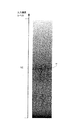
しかしながら上記従来の誤差拡散による中間調処理では、プリント画像には、その画像の全体的な画質を劣化させる傾向をもつドット(artifact)が生成されてしまうという問題があった。2種類の問題となるドットが認識されている。即ち、ハイライト領域(例えば、極端に低濃度或いは極端に高濃度の領域)に現れる予期せぬ連続的なドットラインと、中濃度領域に現れるテクスチュアやパターンの繰り返しである。これらの画質を劣化させる原因となるドットは、図1と図2とにより詳細に図示されている。
【0005】
図1において、10は8×4グリッドのパッチの標準的な誤差拡散による中間調処理のプリント出力を表し、各パッチは一定のグレーレベルをもっているが、パッチからパッチへは順にそのグレーレベルが増加する。図1の8×4グリッドは低濃度グレー領域のみのパッチを含むが、約10%のグレーレベルを超える濃度のパッチを含んではいない。連続するドットラインは、例えば、11や12のようにすぐに明らかである。これらの連続するドットラインパターンは、これを見る者にとって、不快なものである。
【0006】
図2は真っ黒の濃度レベルから真っ白の濃度レベルへと進むグレーレベルウェッジを図示したものである。中濃度レベルにおいて、16で示されているようにパターンやテクスチュアの繰り返しがすぐに明らかである。これらのテクスチュアもまたこれを見る者にとって、不快なものであり、プリント画像全体の品質を劣化させる。
【0007】
これらの画質劣化を生じさせるドット(artifact)が生成されたり、存在したりすることは、よく文書としても知られており、これらの出現を減らし、全体的な画質の向上を図るためによく研究がなされてきた。以前に提案された1つの技術は、画像入力に基づいて、誤差拡散の重みを変えることである。そのような技術の例は、欧州特許第808055号のOstromoukhov特許やEschbach著“Reduction Of Artifacts In Error Diffusion By Means Of Input-Dependent Weights”,Journal of Electronic Imaging, 1993年10月,352-358ページに記述されている。画質劣化を生じさせるドット(artifact)を減らすために必ずしも知られる必要はないが、他の既知の技術には、例えば、Eschbach著“Error-Diffusion Algorithm With Edge Enhancement”,Journal of The Optical Society of America, 1991年12月,1844-1850ページに記述されているように、画像値に基づく変更を含む、連続する濃度画像値と累積誤差との和が比較される閾値を動的に変える技術が含まれている。
【0008】
そのような技術は、本発明においては、誤差拡散の重み及び/或いは閾値は累積出力誤差に基づいて、或いは、画像ソースデータと累積出力誤差に基づいて変更されるので、本発明とは異なる。
【0009】
本発明は上記従来例に鑑みてなされたもので、誤差拡散の重み及び/或いは閾値を出力誤差に基づいて、或いは、画像データと累積出力誤差に基づいて変更することにより、誤差拡散による中間調処理において出力される画質劣化を生じさせるドット(artifact)を減少させる中間調処理方法を提供することを目的とする。好適には、出力誤差に基づいた、或いは、画像ソースデータと累積誤差との和に基づいた、直接的に誤差拡散による中間調処理についての実際の誤差値及び/或いは閾値や出力誤差を提供するルックアップテーブルが備えられる。
【0010】
【課題を解決するための手段】
従って上記目的を達成するために本発明をある一面から見ると、本発明は誤差拡散法を用いて画像データを中間調処理するための中間調処理方法であって、閾値と中間調処理を行う注目画素の画素値に累積誤差を加えた値とを比較して、前記注目画素の中間調出力値を決定する決定工程と、前記中間調出力値と前記注目画素の画素値に累積誤差を加えた値との差分である出力誤差を、前記注目画素の近傍に位置する画素に所定の分配比率で拡散する拡散工程とを有し、前記拡散工程は、前記出力誤差を拡散するための前記所定の分配比率を前記出力誤差値に基づいて、周期的に変化させることを特徴とする。
【0011】
また本発明を別の面から見ると、本発明は、誤差拡散法を用いて画像データを中間調処理するための中間調処理方法であって、閾値と中間調処理を行う注目画素の画素値に累積誤差を加えた値とを比較して、前記注目画素の中間調出力値を決定する決定工程と、前記中間調出力値と前記注目画素の画素値に累積誤差を加えた値との差分である出力誤差を、前記注目画素の近傍に位置する画素に所定の分配比率で拡散する拡散工程とを有し、前記拡散工程は、前記出力誤差を拡散するための前記所定の分配比率を、前記注目画素値に累積誤差を加えた値に基づいて変化させることを特徴とする。
【0012】
さらに本発明を別の面から見ると、本発明は、誤差拡散法を用いて画像データを中間調処理する中間調処理装置であって、閾値と中間調処理を行う注目画素の画素値に累積誤差を加えた値とを比較して、前記注目画素の中間調出力値を決定する決定手段と、前記中間調出力値と前記注目画素の画素値に累積誤差を加えた値との差分である出力誤差を、前記注目画素に近傍に位置する画素に所定の分配比率で拡散する拡散手段とを有し、前記拡散手段では、前記出力誤差を拡散するための前記所定の分配比率を前記出力誤差値に基づいて、周期的に変化させることを特徴とする。
【0013】
さらにまた本発明を別の面から見ると、本発明は、誤差拡散法を用いて画像データを中間調処理する中間調処理装置であって、閾値と中間調処理を行う注目画素の画素値に累積誤差を加えた値とを比較して、前記注目画素の中間調出力値を決定する決定手段と、前記中間調出力値と前記注目画素の画素値に累積誤差を加えた値との差分である出力誤差を、前記注目画素の近傍に位置する画素に所定の分配比率で拡散する拡散手段とを有し、前記拡散手段では、前記出力誤差を拡散するための前記所定の分配比率を、前記注目画素値に累積誤差を加えた値に基づいて変化させることを特徴とする。
【0014】
なお、上記の簡単な要約が備えられることにより、本発明の特徴はすばやく理解されると思われる。しかしながら、本発明のより完全な理解は、添付図面と関連した次に示す好適な実施形態の詳細な説明とを参照することによって得られるものである。
【0015】
【発明の実施の形態】
以下添付図面を参照して本発明の好適な実施の形態について詳細に説明する。
【0016】
図3は、本発明の実施形態に関連して用いられるコンピュータ装置の外観を示す図である。コンピュータ装置20はホストプロセッサ23を含んでいる。ホストプロセッサ23は、パーソナルコンピュータ(以下、“PC”という)を有している。なお、そのPCは、マイクロソフトのウィンドウズ95のようなウィンドウ環境で動作するIBM PC互換のコンピュータが望ましい。そのコンピュータ装置20には、カラーモニタなどを有したディスプレイ画面22、テキストデータやユーザコマンドを入力するためのキーボード26、ポインティングデバイス27が設けられている。ポインティングデバイス27は、好適には、ディスプレイ画面22に表示されるオブジェクトを指示したり、操作するマウスを有している。
【0017】
コンピュータ装置20は、コンピュータディスク25やフロッピィディスクドライブ24のようなコンピュータ可読メモリ媒体を有している。プロッピィディスクドライブ24は、コンピュータ装置20が、データやアプリケーションプログラムなどのようなフロッピイディスクに格納された情報にアクセスできる手段を備えている。コンピュータ装置20には、同様のCD−ROMインタフェース(不図示)が備えられ、これによって、コンピュータ装置20はCD−ROMに格納された情報にアクセスできる。
【0018】
ディスク25は、オペレーティングシステム111、アプリケーションプログラム112、プリンタドライバ114、他のアプリケーションプログラム、ファイル、ドライバ119のようなデバイスドライバを構成するように、CPU100によって実行可能なプログラム命令シーケンスを格納するコンピュータ可読媒体の一例である。アプリケーションプログラムは、これによって、ホストプロセッサ23がファイルを生成し、ディスク25のそれらのファイルを操作し、格納し、ディスプレイ画面22を介してユーザにそれらファイルにあるデータを提示し、プリンタ30を介してプリントを行うことができるプログラムである。ディスク25は、また、オペレーティングシステムを格納する。これは、上述のように、ウィンドウズ(WINDOWS(登録商標))95のようなウィンドウオペレーティングシステムが望ましい。デバイスドライバもまたディスク25に格納される。少なくとも1つのデバイスドライバはプリンタドライバ114を含み、そのドライバはプリンタ30とのソフトウェアインタフェースを提供する。ホストプロセッサ23とプリンタ30との間でデータ交換は、後でより詳細に説明するが、プリンタドライバによってなされる。
【0019】
プリンタ30は好適にはカラーインクジェットプリンタであり、これは、インク液滴を紙、透明のシートなどの記録媒体に吐出することによって画像を形成する。望ましいプリンタの1つが米国特許出願第08/972113号“解像度を異ならせることのできるマルチヘッドプリンティング(Multi-Head Printing With Differing Resolution)”で説明されている。その出願は、ここで十分に説明されているかのように参照として組み込まれる。本発明の実施形態で用いられているように、しかしながら、プリンタ30は、レーザビームプリンタ、サーマルプリンタ、ドットマトリクスプリンタ、或いは、マルチヘッドインクジェットプリンタのような、1以上の濃淡レベルをもったドットを配置することによって記録媒体上に画像を形成する、他の種類のプリンタであっても良い。
【0020】
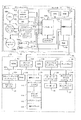
図4は、ホストプロセッサ23とプリンタ30との内部構成を示すブロック図である。図4において、ホストプロセッサ23はコンピュータバス101とインタフェースをもつプログラム可能なマイクロプロセッサのような中央処理装置(CPU)100を有している。また、コンピュータバス101には、ディスプレイ22とインタフェースをもつディスプレイインタフェース102、双方向通信ライン106を介してプリンタ30とインタフェースをもつプリンタインタフェース104、フロッピィディスクドライブ24とインタフェースをもつフロッピィディスクインタフェース124、キーボード26とインタフェースをもつキーボードインタフェース109、ポインティングデバイス27とインタフェースをもつポインティングデバイスインタフェース110が接続されている。
【0021】
ランダムアクセスメインメモリ(以下、“RAM”という)116は、コンピュータバス101とインタフェースをもち、CPU100に記憶装置とのアクセスを提供している。特に、プリンタドライバ114に関連したシーケンスのような格納されたプログラム命令シーケンスの実行時、CPU100はそれらの命令シーケンスをディスク25(或いはネットワークインタフェースを介してアクセスされるコンピュータ可読媒体のような他の記憶媒体)からRAM116にロードし、RAM116から格納されたそれらプログラム命令シーケンスを呼び出して実行する。なお、ウィンドウオペレーティングシステムで利用可能な標準的なディスク−スワッピング技術により、メモリのセグメントがディスク25とRAM25との間でスワップできることを理解されたい。
【0022】
ホストプロセッサ23の読出し専用メモリ(以下、“ROM”という)43は、スタートアップ命令シーケンスやキーボード26の動作のための基本入出力オペレーティングシステム(BIOS)シーケンスのような不変の命令シーケンスを格納する。
【0023】
ディスク25はまた、特定のアプリケーションプログラムの制御下で、ディスプレイ22によって表示されたり、或いは、プリンタ30によってプリントされたりすることがあるかもしれないようなカラー画像ファイルを格納しても良い。また、アプリケーションプログラムの実行中に動的に生成されることがあるかもしれないそのようなカラー画像ファイルは、カラー画像の各画素についてのカラー画像データを格納したり、或いは、エンコードする。1つのポピュラーな記憶或いは符号化フォーマットは、カラー画像の各画素について赤、緑、青(RGB)のカラー原色値を、RGB成分各々について8ビットで表現して格納することである。このフォーマットによって格納され、或いは、符号化された結果得られるカラー画像には、カラー画像の各画素を28×28×28=1670万の異なる色のいずれかで表現する能力が備えられる。そのようなフォーマットは、しばしば、“トゥルーカラー(true color)”或いは“24ビットカラー”と呼ばれる。そのような画像をプリントするために、その画像の各画素は、一般には、シアン、マゼンタ、イエロ、ブラック(CMYK)のような4つの原色各々についての値へと変換される。しかしながら、各画素に関し、プリンタ30は、C,M,Y,Kの各色平面において、1つの濃度の濃淡(バイナリプリンタの場合には)を、或いは、数段階の濃度の濃淡(マルチグラデーションプリンタの場合には)をプリントできるのみである。本発明に従う中間調処理の目的は、コンピュータ20に格納された多値画像データをプリンタ30のために適当な出力値へと変換することである。
【0024】
再び、図4において、プリンタ30はプリントコントローラ120とプリンタエンジン131とを含んでいる。プリントコントローラ120は、コンピュータ化された電子機器を有しており、これを用いてプリンタエンジン131を制御する。そして、プリンタエンジン131は、プリントキャリッジとともにキャリッジモータやラインフィードモータ、また、プリント出力を得るための記録ヘッドのような物理的な機器を含んでいる。図4に示されているように、プリントコントローラ120は、8ビット或いは16ビットマイクロプロセッサのようなCPU121、ROM122、制御ロジック124、バス126に接続されたI/Oポート127を含んでいる。また、制御ロジック124にはRAM129が接続されている。I/Oポート127には、EEPROM132が接続されている。
【0025】
プリンタエンジン131は、ラインフィードモータドライバ61aによって制御されるラインフィードモータ61とキャリッジモータドライバ66aによって制御されるキャリッジモータ66を含んでいる。デュアル記録ヘッド130aと130bは着脱可能な記録ヘッドであり、不図示のプリンタキャリッジによって移動される。また、そのデュアル記録ヘッドは、記録媒体にプリント画像を形成するためにインク吐出ノズルを備えるとともに、着脱可能な記録ヘッドの存在とその特性に関してフィードバックをするためのセンサを備えている。また、プリンタエンジン131には、可聴ブザー128、カバーセンサ134、ユーザによる操作可能なスイッチ133、指示LED135が設けられている。
【0026】
制御ロジック124は、記録ヘッド130aと130bのノズルに制御信号を供給し、さらに、I/Oポート127を介して、ラインフィードモータドライバ61aとキャリッジモータドライバ66aの制御ロジックを提供している。I/Oポート127は、記録ヘッド130a、130bからのセンサ出力、センサ134とスイッチ133からのセンサ出力を受信し、さらに加えて、ブザー128とLED135についての制御信号を供給する。上述のように、I/Oポート127は、制御ロジック124からラインフィードモータドライバ61aとキャリッジモータドライバ66aへの制御信号のチャネルとなっている。
【0027】
ROM122は、フォントデータ、プリンタ30を制御するために用いられるプログラム命令シーケンス、プリンタ動作のための他の不変データとを格納する。RAM129は、ROM122のプログラム命令シーケンスによって定義されるプリントバッファに、記録ヘッド130aと130bによるプリント出力のためのプリントデータを格納する。EEPROM132は、記録ヘッド構成や記録ヘッドの位置合わせパラメータのようなプリンタ情報のため、不揮発性再プログラム可能なメモリを提供する。EEPROM132はまた、プリンタ、プリンタドライバ、記録ヘッド、記録ヘッドの位置合わせ、インクカートリッジのインクの状態などを識別するパラメータを格納し、これら全てはホストプロセッサ23のプリンタドライバ114に備えられて、ホストプロセッサ23にプリンタ30の動作パラメータを伝え、プリンタドライバ114がプリント出力を変更し、プリンタ30の種々の構成を取り込めることができるようにしても良い。
【0028】
図5は、本発明の1つの実施形態に従う誤差拡散による中間調処理を構成する、格納されたコンピュータ実行可能なプログラム命令シーケンスを図示したフローチャートである。この第1の実施形態で示されている処理ステップとともに、残りの実施形態で示されている処理ステップは、ディスク25のプリンタドライバ114に格納されていることが好ましく、これらはCPU100によって実行され、中間調処理されたプリンタ出力データを提供する。このデータは、ホストプロセッサ23から双方向インタフェース106を介してプリンタ30に送信される。プリンタ30よりホストプロセッサ23において誤差拡散による中間調処理を実行することが好適である理由としては、ホストプロセッサ23が一般にはプリンタ30よりも処理能力が高いことがある。従って、図5に示された格納されたプログラム命令シーケンスはプリンタ30よりもホストプロセッサ23の方が、より速く実行され、多値画像入力データはプリント出力データに変換される。もちろん、ある環境では、その格納されたプログラム命令シーケンスがプロセッサ30によって実行されることが好ましい場合もあることは理解されたい。その場合、図5に示された格納されたプログラム命令シーケンスはROM122に格納し、CPU121によって実行しても良い。
【0029】
ここで説明した全ての実施形態のように、図5の実施形態では、各ラスタラインにおいて、各画素の処理を一様に左から右へと行うことを前提としている。しかしながら、全ての実施形態を変形して、単に誤差が拡散される方向を変えることにより、例えば、蛇行するような順序、或いは、ブルーノイズのような順序のような異なる処理順序にしても良い。
【0030】
一般的に言って、図5で図示される格納されたプログラム命令シーケンスは、誤差拡散による中間調処理を含んでおり、この処理により多値画像データがプリンタ出力データに変換される。注目画素の値とその累積誤差との和がアクセスされ、出力濃淡レベルが閾値と注目画素とその累積誤差との和との間の比較に基づいて決定され、出力誤差が計算され、その出力誤差が近接画素に拡散される。近接画素への拡散は、計算された誤差拡散の重みに基づいており、その重みは注目画素の値とその累積誤差との和に依存している。
【0031】
さらに詳しく説明すると、ステップS501は注目画素とその累積誤差との和についての値にアクセスすることにより、注目画素についての誤差拡散処理を開始する。“累積誤差”とは、例えば、以前になされた誤差拡散処理を通してその注目画素に近接する画素のような、他の画素について前になされた誤差拡散処理から累積された誤差を意味する。この点について、誤差が計算され、その誤差が直接にオリジナル画像の値に加算されることで拡散されることを意味するので、一部がメモリバッファにロードされる入力画像データに関し、本発明を実施する場合には、元の位置で中間調処理されることが一般には好ましい。従って、本来的には、オリジナル画像データと累積誤差について、別々のバッファに格納する必要はないので、この処理ではメモリに関する要求はより小さくなるという結果になる。
【0032】
ステップS502は、注目画素についての出力濃淡レベルと出力誤差とを決定する。出力濃淡レベルを決定するために、閾値と、注目画素についての値と累積誤差との和との比較がなされる。多値画像データの範囲の半分のように、その閾値は定数で良い(8ビット画像データの場合には、固定閾値“127”を選択しても良い)。あるいは、その閾値は変数でも良い。具体的には、その閾値は、画像データのラスタ格子の注目画素の場所に基づいて変化しても良いし、注目画素の画像データ値に基づいて変化しても良いし、或いは、その組み合わせに基づいて変化しても良い。
【0033】
ステップS502における出力誤差は、所望の出力値(注目画素の値と累積誤差との和によって表現されるように)と実際のプリント値との間の差を得ることにより決定される。例えば、その注目画素についての画像データと累積誤差との和が、所望の出力値が濃度範囲の4分の1であることを示しているなら、バイナリプリンタでは、出力濃淡レベルとしておそらくは“ゼロ”が選択されるであろう。この例では、そのとき、その出力誤差は4分の1であり、これは、注目画素についての画像値と累積誤差との和と、その注目画素について実際に選択された出力値との間の差を表現している。
【0034】
ステップS503では、誤差拡散の重みが計算され、その注目画素に近接する画素に出力誤差を拡散するため、後に続く処理で用いられる。本発明の実施形態では、誤差拡散の重みは、注目画素の値とその累積誤差との和に基づいて計算される。このことは、図6A〜図6Cに図示されている。
【0035】
具体的には、図6Aは、注目画素40についての誤差拡散の重みを示している。その誤差拡散の重みはe0、e1、e2、e3、及び、erとラベルが付けられている。図6Aに示されているように、誤差についての最も大きな割合が、隣接する画素であり、かつ、注目画素の右側にある画素であるe3とラベルが付されている画素に拡散され、その割合はe3=129÷255である。誤差について次に大きな割合が、隣接する画素であり、かつ、注目画素の下側にある画素に拡散され、その重みはe2=70÷255である。続いて、誤差についてのより小さな割合が、近接する画素であり、かつ、注目画素の左下側にある2つの画素に拡散され、図示されているように、その重みはe1=35÷255、e0=20÷255である。最後に、丸め誤差と整数計算の効果とを考慮するために、いくらかの残余誤差が、すぐ右側の隣接画素に拡散され、図示されているように、それはer=全出力誤差−e0−e1−e2−e3である。
【0036】
図6Aに示される誤差拡散の重みは、中立的な誤差拡散の重みであり、注目画素の値とその累積誤差との和が、mを任意の整数であるとすると、4m或いは4m+2に等しいときに用いられる。従って、ステップS503では、注目画素とその累積誤差との和の値が4m或いは4m+2に等しいなら、そのとき、図6Aに示される誤差拡散の重みが計算される。
【0037】
これに対して、注目画素とその累積誤差との和の値が4m+1に等しいなら、そのときには、図6Bに示される誤差拡散の重みが計算される。図6Bの誤差拡散の重みは、右側に隣接する画素を重視し、e3についての値を20%増加させる一方、e0、e1、e2についての値をおおよそ20%減少させるようにして、各重みを得ている。
【0038】
図6Cは、注目画素とその累積誤差との和の値が4m+3に等しい場合に、計算される誤差拡散の重みを示している。図6Cに示される誤差拡散の重みは、左下方向への重み付けを重視し、e0、e1、e2についての図6Aに示した誤差拡散の重みを20%増加させる一方、e3についての誤差拡散の重みをおおよそ減少させることによって、各重みを得ている。
【0039】
図6A〜図6Cに示したようにして誤差拡散の重みを計算することにより、図7に示されるように、誤差拡散の重みについての周期的な変化が得られる。具体的に言うと、図7は注目画素の値とその累積誤差との和に基づいて誤差拡散の重みがどのように変化するかを図示している。図7から分かるように、4つの段階をもった周期的な変化は、(図6Cに示されているように)左下側方向を重視した重み付けから、(図6Aに示されているように)中立的な重み付けを経て、(図6Bに示されているように)右側方向を重視した重み付けへというように変化する。画像の値とその累積誤差との和に依存した、誤差拡散の重みにおけるそのような周期的な変化は好ましいものである。
【0040】
さて、図5に戻って説明を続けると、ステップS504では出力誤差を計算された誤差拡散の重みに基づいて近接する画素へと拡散する。具体的には、ステップS503において計算された誤差拡散の重みに基づいて、出力誤差が、図6A〜図6Cに図示されたような方法で、近接画素に配分される。それから、ステップS504では全画像が処理されたか、或いは、1記録バンドのような記録に十分な部分が処理されたかを判断する。もし、全画像或いは記録に十分な部分がまだ記録されていないなら、処理はステップS505からステップS501に戻り、所定の走査パターンにおける別の注目画素についての誤差拡散処理を続行する。これに対して、もし、全画像或いは1記録バンドのような記録に十分な部分が処理されたなら、処理はステップS505からステップS506へと進む。ステップS506では、出力濃淡レベルがホストプロセッサ23から双方向インタフェース106を介してプリンタ30へと送信されるようにし、これによってプリント出力がなされる。
【0041】
図8は、本発明の第2実施形態を図示したものである。図8の実施形態が第1の実施形態と異なる1つの点は、誤差拡散の重みが注目画素の値とその累積誤差との値との和に基づくのではなく、むしろ、出力誤差に基づいて計算される点である。
【0042】
図8に示される処理ステップはディスク125のプリンタドライバ114に格納され、CPU125によって実行されプリントデータをプリンタ30への双方向バス106に提供する。しかしながら、上述のように、図8に示す処理ステップをROM122に格納して、プリンタ30のCPU121で実行することも可能である。
【0043】
ステップS801とS802とは図5の対応ステップと似た処理であり、注目画素についての値とその累積誤差にアクセスする処理と、出力誤差とともに出力濃淡レベルの決定をする処理とを備える。
【0044】
ステップS803では、その出力誤差に基づいた計算がなされ、誤差拡散の重みが計算される。適切な誤差拡散の重みは図6A〜図6Cに示されている。
【0045】
ステップS804では、出力誤差が計算された誤差拡散の重みに基づいて近接する画素へと拡散される。もし、全画像或いは1バンドのような画像の十分な部分がまだ処理されていないなら、処理はステップS805からステップS801に戻る。これに対して、全画像或いはその十分な部分が処理されたなら、処理はステップS806に進み、そのプリント出力データはプリンタ30に送信され、これにより、プリント出力がなされる。
【0046】
図9は本発明の第3実施形態を図示したものである。第3実施形態が第1〜第2実施形態と異なる1つの点は、予め計算された誤差拡散のパラメータを格納するためにルックアップテーブルが用いられる点である。図9の実施形態において、そのルックアップテーブルに格納されるものは、誤差拡散の重みではなく、むしろ、実際の誤差拡散の値である。誤差拡散の重みではなくむしろ実際の誤差拡散の値を格納することによって、その出力誤差に誤差拡散の重みを乗ずるという乗算演算の必要を省き、誤差拡散の値を得ることができる。
【0047】
第3実施形態では、誤差拡散の値を予め計算すること、また、これをルックアップテーブルに格納することは、誤差拡散処理中のルックアップテーブルの使用とは論理的にも明らかに異なるものである。図9に破線を挿入することで、この違いを強調している。前もった計算やルックアップテーブルへの格納を、そのルックアップテーブルの使用に先だって、例えば、プリンタドライバ114の設計中に、完全に行っておき、そのプリンタドライバ114に適切なルックアップテーブルを予め格納して、そのプリンタドライバ114をエンドユーザに配送できるようにすることが好ましい。或いは、プリンタドライバ114がプリント動作に先立って動的に計算とルックアップテーブルへの格納を行い、変化する誤差拡散の値についての必要を小さくしたり大きくするかもしれない特定の画像の特徴を組み込むこともできる。
【0048】
一般的に言って、図9に示される処理ステップには、画像データ値と累積誤差との和の関数として予め計算された誤差拡散の値を格納するルックアップテーブルへのアクセスによる誤差拡散の中間調処理が備えられている。注目画素を中間調処理するために、その値と累積誤差との和がそのルックアップテーブルをアクセスするために用いられ、これによって、誤差拡散の値を得ている。そのルックアップテーブルはプリント出力値を提供することが好ましいが、もし、そのルックアップテーブルがプリント出力値を提供していなくとも、その値は注目画素の値とその累積誤差との和とある閾値とを比較することによって得られる。そのルックアップテーブルから得られる誤差拡散の値は、その後、近接画素が注目画素になったときの後続の処理のために、その近接画素に加えられる。
【0049】
より詳しく説明すると、ステップS901ではプリント出力データ値とともに誤差拡散の値を前もって計算する。その誤差拡散の値とプリント出力データ値とは両方とも画像ソースデータと累積誤差との和の全てのありえる値に基づいて計算される。従って、たとえ8ビット画像データの値が0〜255の範囲の中にあるようにされていても、誤差累積の処理の結果は、オリジナル画像データから127を引いたものよりも20%だけ大きくなるか、或いは、オリジナル画像データに128を加えたものよりも最大20%大きくなるかもしれない。(この“20%”ファクタは、この実施形態では誤差を周期的に20%だけ増加させるという事実に基づいた最悪の場合の評価である。)従って、オリジナル画像データの値が0〜255の範囲にあるのであるから、誤差拡散の値とプリント出力データ値とは、−153〜409の範囲にある画像ソースデータとその累積誤差との和についてのありえる値各々について計算される。
【0050】
ステップS902は、ルックアップテーブルに、前もって計算した値を画像データ値とその累積誤差との和の関数として格納する。図10は、そのようなルックアップテーブルの代表的な例を図示している。
【0051】
図10において、−153〜409の範囲において画像ソースデータと累積誤差との和の各値について、誤差拡散の値、e0、e1、e2、e3、及び、erが、プリント出力データ値とともに格納される。その誤差拡散の値を得るために用いられる割合配分は、図6A〜図6Cと関連して上述したように、ソースデータと累積誤差との和に依存している。図6A〜図6Cに関連してさらに説明したように、その誤差拡散の値を得るために用いられる重みは、周期的に変化することが好ましい。
【0052】
ステップS901とS902とがどのように前もって計算を行い、ルックアップテーブルに格納するのかを説明する目的のために、図10に示されているように、ソース画像データとその累積誤差との和が−126に等しいときの状態を考慮する。そのような環境では、プリント出力データ値はゼロであると計算され,その結果、出力誤差は−126−0=−126となる。−126というソース画像データと累積誤差との和は、4m+2の形をしているので、図6Aに示される誤差係数が用いられて、−126の出力誤差を拡散する。図6Aに示される重みを−126の出力誤差に適用すると、図10に示されるような誤差拡散の値、e1〜erを生み出す。
【0053】
同様にして、ソース画像データと累積誤差との和に基づいて、近接画素に拡散される出力誤差の割合を変化、好適には、周期的に変化させながら、ソース画像データと累積誤差との和のありえる値各々について、誤差拡散の値とプリント出力データ値とが前もって計算され、ルックアップテーブルに格納される。
【0054】
さて、図9に戻って説明を続けると、ステップS903では、注目画素の値とその累積誤差との和の値にアクセスする。ステップS904ではルックアップテーブルにアクセスして誤差拡散の値とプリント出力データ値とを取得する。ステップS905では誤差拡散の値を近接画素に拡散する。全画像データ或いはその内の十分な部分がまだ処理されていないなら、画像データの十分な部分(例えば、1バンド)の処理が完了するまで、処理はステップS906からステップS903に戻る。その画像データの十分な部分が処理されたとき、ステップS907ではプリント出力データ値がホストプロセッサ23から双方向インタフェース106を経てプリンタ30に送信されるようにし、これにより、プリント出力がなされる。
【0055】
図11は本発明の第4実施形態に従う処理ステップを図示したものである。第4実施形態が第3実施形態と異なる1つの点は、ルックアップテーブルが誤差拡散の値を、ソース画像データと累積誤差との和の関数ではなく、むしろ、出力誤差の関数として格納する点である。さらに、誤差拡散の割合は変化し、好適には、ソース画像データと累積誤差との和に基づいてではなく、むしろ、出力誤差に基づいて周期的に変化する。
【0056】
従って、ステップS1101は、出力誤差の値のすべてのとりえる値各々について誤差拡散の値を前もって計算する。この場合、出力誤差は−127〜128の範囲にあり、或いは、これらを20%だけ増すと、−153〜154の範囲にある。その誤差拡散の値は、出力誤差に基づいて変化する、好適には周期的に変化する誤差拡散の重みに基づいている。
【0057】
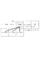
ステップS1102は、出力誤差の関数としてアクセス可能なように、前もって計算された値をルックアップテーブルに格納する。ステップS1102に従うルックアップテーブルを図示した例が、図12に示されている。
【0058】
具体的に説明すると、図12において、ルックアップテーブルは−153〜154の間で変化する出力誤差によってアドレスされる。各出力誤差において、誤差拡散の値、e0〜erが格納される。その誤差拡散の値は、図6A〜図6Cに示された誤差拡散係数のような誤差拡散係数に基づいて、出力誤差を配分することによって得られる。図12の右側に図示的に示されているように、誤差拡散係数は出力誤差に従って変化し、好適には、(図6Bに対応して)右側方向に誤差拡散係数が増加するものから、(図6Aに対応して)中立的な誤差拡散係数をもつものを経て、(図6Cに対応して)左下側方向に誤差拡散係数が増加するというように周期的に変化する。図12に示したルックアップテーブルのより完全な理解を得るために、値の1つである、−153についてより詳細に検証する。−153は4m+3の形をしているので、図6Cに示した誤差拡散係数が適用できる。これらの誤差拡散係数を−153の出力誤差に適用すると、図12に示した誤差拡散の値が得られる。
【0059】
さて、図11に戻って説明を続けると、ステップS1101とS1102とは誤差拡散による中間調処理に先立って、好適には、プリンタドライバ114の設計時に実行されることが好ましい。この場合、誤差拡散の値は、プリンタドライバのルックアップテーブルに格納され、エンドユーザに配布される。或いは、そのルックアップテーブルが、誤差拡散による中間調処理に先立って動的に計算され、特定の画像処理条件、例えば、誤差拡散係数の変化をより大きな程度にまで、或いは、より小さな程度にすることを必要とするような条件を組み込むことができるようにしても良い。
【0060】
画像データの誤差拡散による中間調処理はステップS1103で開始され、そのステップでは、注目画素についての画像データ値とその累積誤差との和がアクセスされる。ステップS1104では、その注目画素についての画像データと累積誤差との和に基づいた注目画素についての出力プリントデータを決定し、その後、その出力誤差を決定する。出力誤差は、注目画素についての所望の値(即ち、画像データ値と累積誤差との和)と実際に出力されるプリントデータとの差である。その出力誤差に基づいて、ステップS1105ではルックアップテーブルをアクセスし、誤差拡散の値を得る。ステップS1106ではその誤差拡散の値を近接画素に加算する。
【0061】
もし、全画像データ或いはその1バンドのような十分な部分がまだ処理されていないなら、処理はステップS1107からステップS1103に戻り、誤差拡散による中間調処理を完成させる。これに対して、全画像データ或いはその十分な部分について誤差拡散による中間調処理がなされたならすぐに、処理はステップS1108に進み、プリンタドライバ114はプリントデータを双方向インタフェース106を介してホストプロセッサ23からプリンタ30に出力し、これによってプリント出力がなされる。
【0062】
図13は本発明の第5実施形態に従う処理ステップを図示したものである。第5実施形態が第3実施形態と異なる1つの点は、誤差拡散の閾値が画像ソースデータとのその累積誤差との和に基づいて変化する点にある。本発明の実施形態として誤差拡散の閾値だけが変化し、誤差拡散の重みは変化しない実施形態を備えることは可能であるが、誤差拡散の閾値と誤差拡散の重みとが変化することが好ましく、従って、第5実施形態では、誤差拡散の重みと誤差拡散の閾値の両方が変化する。この誤差拡散の重みと誤差拡散の閾値との変化は周期的な変化であることが好ましく、さらに、異なる周期で周期的な変化をすることが好ましい。第5実施形態では、誤差拡散の重みの周期的な変化は4つの段階をもっており、一方、誤差拡散の閾値の周期的な変化は3つの段階をもっている。周期的な変化が異なる周期をもっていると、2つの周期の間の干渉をより小さくすることができる。
【0063】
また、閾値の変化が画像ソースデータと累積誤差との和に依存するのではなくむしろ、出力誤差に依存した実施形態を備えることも可能である。
【0064】
一般的に言って、図13の処理ステップでは、予め計算された誤差拡散の値とプリンタ出力値とを画像データ値と累積誤差との和との関数として格納したルックアップテーブルにアクセスすることにより、誤差拡散による中間調処理を備えている。注目画素を誤差拡散による中間調処理を行うために、その値と累積誤差との和がルックアップテーブルにアクセスするために用いられ、これによって、プリンタ出力値と誤差拡散の値を得る。ルックアップテーブルから得られた誤差拡散の値は、その後、近接画素に加算され、その近接画素が注目画素になるときの後続する処理に備える。プリンタ出力値はプリンタへの出力のために格納される。
【0065】
従って、ステップS1301では、誤差拡散の値、閾値、プリンタ出力データ値を、ソースデータとその累積誤差との和のありえる値各々に関して、前もって計算する。この実施形態では、誤差拡散の閾値が、128という名目上の閾値の周りに周期的に±25%変化することが許されている。加えて、誤差拡散の重みは名目上の値の周りに±20%変化することが許されている。従って、たとえ8ビット画像データの値が0〜255の範囲にあるようにされていても、閾値決定の処理の結果、出力誤差は−127より25%小さく、或いは、128より最大25%大きくなり得る。また、誤差累積の処理の結果、その誤差は±両方向にさらに20%増加することもありえる。従って、誤差拡散の値とプリンタ出力値とは、−191〜447の範囲において画像ソースと累積誤差との和のありえる値各々について計算される。
【0066】
図14Aは、誤差拡散の値の変化における周期的な性質と、閾値の変化における周期的な性質とを図示したものである。ここで、図14Aはただ説明を目的としたものであり、ルックアップテーブルを代表しているものではないこと(むしろ、図14Bがルックアップテーブルの代表的なものである)を強調しておきたい。図14Aは、誤差拡散の重みが、4つの段階で、ソース画像データと累積誤差との和の各値に関して、どのように循環しているかを示したものである。第5実施形態では、図6A〜図6Cに図示された周期的な変化が用いられる。加えて、図14Aは誤差拡散の閾値が、3つの段階で、どのように周期的に変化するかを示したものである。ソース画像データと累積誤差との和が3wの形であるときには、閾値として“96”が割り当てられる。また、ソース画像データと累積誤差との和が3w+1の形であるときには、閾値として“128”が割り当てられる。さらに、ソース画像データと累積誤差との和が3w+2の形であるときには、閾値として“160”が割り当てられる。そのような構成により、誤差拡散の重みの周期とは異なる周期をもつ閾値の周期的な変化が備えられる。
【0067】
ステップS1302では、誤差拡散の値とプリンタ出力値とを予め計算し、これをソース画像データと累積誤差との和の関数としてルックアップテーブルでアクセス可能なようにする。ステップS1302に従うルックアップテーブルの図示的な例が図14Bに示されている。
【0068】
図14Bにおいて、−191〜447の範囲において画像ソースデータと累積誤差との和についての各値について、誤差拡散の値、e0、e1、e2、e3、及び、erが、プリント出力データ値とともに格納される。誤差拡散の値を得るために用いられる割合は、図14Aに関連して上述したように、図6A〜図6Cに示した重みを用い、ソースデータと累積誤差との和に依存している。そのプリンタ出力値は、図14Aに関連した上述したように、周期的に変化する閾値と、ソース画像データと累積誤差との和とを比較することによって得られる。
【0069】
ステップS1301とS1302がどのように誤差拡散量とプリンタ出力値とを前もって計算し、ルックアップテーブルにそのような値を格納するのかを説明する目的のために、図14Bに示されているように、ソース画像データとその累積誤差との和が111に等しいときの状態を考慮する。そのような環境では、閾値は96であり、その結果、プリンタ出力値は“1”(これはドットをプリントすることを意味する)となる。111と255との差(即ち、プリントされるドットに対応した濃度値)は、−144という出力誤差を生む。図6Cに示された誤差拡散係数の値に従うと、出力誤差−144の拡散によって、図14Bに示される誤差拡散の値、e0〜erを生み出す。
【0070】
再び、図13において、ステップS1301とS1302とは誤差拡散による中間調処理に先立って、好適には、プリンタドライバ114の設計時に、実行されることが好ましい。この場合、その誤差拡散の値とプリンタ出力値とはエンドユーザへの配布のために、プリンタドライバのルックアップテーブルに格納される。或いは、そのルックアップテーブルは誤差拡散による中間調処理に先立って動的に計算され、例えば、誤差拡散係数や誤差拡散の閾値の変化をより大きな程度或いはより小さな程度にすることを必要とするような条件のような、特定の画像処理条件を組み込むことができるようにしても良い。
【0071】
画像データの誤差拡散による中間調処理はステップS1303で開始され、注目画素の画像データとその累積誤差との和がアクセスされる。ステップS1304ではルックアップテーブルにアクセスして、誤差拡散の値とプリント出力データ値とを取得する。ステップS1305では、誤差拡散の値を近接画素に加算する。もし、全画像データ或いは1バンドのようなその十分な部分がまだ処理されていないなら、その全画像データあるいはその十分な部分が処理されるまで、処理はステップS1306からステップS1303に戻る。全画像データ或いはその十分な部分が処理完了したなら、処理はステップS1307に進み、プリント出力データ値がホストコンピュータ23から双方向インタフェース106を経てプリンタ30に送信されるようにし、これによってプリント出力がなされる。
【0072】
なお、以上の実施形態において、記録ヘッドから吐出される液滴はインクであるとして説明し、さらにインクタンクに収容される液体はインクであるとして説明したが、その収容物はインクに限定されるものではない。例えば、記録画像の定着性や耐水性を高めたり、その画像品質を高めたりするために記録媒体に対して吐出される処理液のようなものがインクタンクに収容されていても良い。
【0073】
以上の実施形態は、特にインクジェット記録方式の中でも、インク吐出を行わせるために利用されるエネルギーとして熱エネルギーを発生する手段(例えば電気熱変換体やレーザ光等)を備え、前記熱エネルギーによりインクの状態変化を生起させる方式を用いることにより記録の高密度化、高精細化が達成できる。
【0074】
その代表的な構成や原理については、例えば、米国特許第4723129号明細書、同第4740796号明細書に開示されている基本的な原理を用いて行うものが好ましい。この方式はいわゆるオンデマンド型、コンティニュアス型のいずれにも適用可能であるが、特に、オンデマンド型の場合には、液体(インク)が保持されているシートや液路に対応して配置されている電気熱変換体に、記録情報に対応していて膜沸騰を越える急速な温度上昇を与える少なくとも1つの駆動信号を印加することによって、電気熱変換体に熱エネルギーを発生せしめ、記録ヘッドの熱作用面に膜沸騰を生じさせて、結果的にこの駆動信号に1対1で対応した液体(インク)内の気泡を形成できるので有効である。この気泡の成長、収縮により吐出用開口を介して液体(インク)を吐出させて、少なくとも1つの滴を形成する。この駆動信号をパルス形状をすると、即時適切に気泡の成長収縮が行われるので、特に応答性に優れた液体(インク)の吐出が達成でき、より好ましい。
【0075】
このパルス形状の駆動信号としては、米国特許第4463359号明細書、同第4345262号明細書に記載されているようなものが適している。なお、上記熱作用面の温度上昇率に関する発明の米国特許第4313124号明細書に記載されている条件を採用すると、さらに優れた記録を行うことができる。
【0076】
記録ヘッドの構成としては、上述の各明細書に開示されているような吐出口、液路、電気熱変換体の組み合わせ構成(直線状液流路または直角液流路)の他に熱作用面が屈曲する領域に配置されている構成を開示する米国特許第4558333号明細書、米国特許第4459600号明細書を用いた構成も本発明に含まれるものである。加えて、複数の電気熱変換体に対して、共通するスロットを電気熱変換体の吐出部とする構成を開示する特開昭59−123670号公報や熱エネルギーの圧力波を吸収する開口を吐出部に対応させる構成を開示する特開昭59−138461号公報に基づいた構成としても良い。
【0077】
さらに、記録装置が記録できる最大記録媒体の幅に対応した長さを有するフルラインタイプの記録ヘッドとしては、上述した明細書に開示されているような複数記録ヘッドの組み合わせによってその長さを満たす構成や、一体的に形成された1個の記録ヘッドとしての構成のいずれでもよい。
【0078】
加えて、上記の実施形態で説明した記録ヘッド自体に一体的にインクタンクが設けられたカートリッジタイプの記録ヘッドのみならず、装置本体に装着されることで、装置本体との電気的な接続や装置本体からのインクの供給が可能になる交換自在のチップタイプの記録ヘッドを用いてもよい。
【0079】
また、以上説明した記録装置の構成に、記録ヘッドに対する回復手段、予備的な手段等を付加することは記録動作を一層安定にできるので好ましいものである。これらを具体的に挙げれば、記録ヘッドに対してのキャッピング手段、クリーニング手段、加圧あるいは吸引手段、電気熱変換体あるいはこれとは別の加熱素子あるいはこれらの組み合わせによる予備加熱手段などがある。また、記録とは別の吐出を行う予備吐出モードを備えることも安定した記録を行うために有効である。
【0080】
さらに、記録装置の記録モードとしては黒色等の主流色のみの記録モードだけではなく、記録ヘッドを一体的に構成するか複数個の組み合わせによってでも良いが、異なる色の複色カラー、または混色によるフルカラーの少なくとも1つを備えた装置とすることもできる。
【0081】
以上説明した実施の形態においては、インクが液体であることを前提として説明しているが、室温やそれ以下で固化するインクであっても、室温で軟化もしくは液化するものを用いても良く、あるいはインクジェット方式ではインク自体を30°C以上70°C以下の範囲内で温度調整を行ってインクの粘性を安定吐出範囲にあるように温度制御するものが一般的であるから、使用記録信号付与時にインクが液状をなすものであればよい。
【0082】
加えて、積極的に熱エネルギーによる昇温をインクの固形状態から液体状態への状態変化のエネルギーとして使用せしめることで積極的に防止するため、またはインクの蒸発を防止するため、放置状態で固化し加熱によって液化するインクを用いても良い。いずれにしても熱エネルギーの記録信号に応じた付与によってインクが液化し、液状インクが吐出されるものや、記録媒体に到達する時点では既に固化し始めるもの等のような、熱エネルギーの付与によって初めて液化する性質のインクを使用する場合も本発明は適用可能である。このような場合インクは、特開昭54−56847号公報あるいは特開昭60−71260号公報に記載されるような、多孔質シート凹部または貫通孔に液状または固形物として保持された状態で、電気熱変換体に対して対向するような形態としてもよい。本発明においては、上述した各インクに対して最も有効なものは、上述した膜沸騰方式を実行するものである。
【0083】
さらに加えて、本発明に係る記録装置の形態としては、コンピュータ等の情報処理機器の画像出力端末として一体または別体に設けられるものの他、リーダ等と組み合わせた複写装置、さらには送受信機能を有するファクシミリ装置の形態を取るものであっても良い。
【0084】
なお、本発明は、複数の機器(例えばホストコンピュータ,インタフェース機器,リーダ,プリンタなど)から構成されるシステムに適用しても、一つの機器からなる装置(例えば、複写機,ファクシミリ装置など)に適用してもよい。
【0085】
また、本発明の目的は、前述した実施形態の機能を実現するソフトウェアのプログラムコードを記録した記憶媒体を、システムあるいは装置に供給し、そのシステムあるいは装置のコンピュータ(またはCPUやMPU)が記憶媒体に格納されたプログラムコードを読出し実行することによっても、達成されることは言うまでもない。
【0086】
この場合、記憶媒体から読出されたプログラムコード自体が前述した実施形態の機能を実現することになり、そのプログラムコードを記憶した記憶媒体は本発明を構成することになる。
【0087】
プログラムコードを供給するための記憶媒体としては、例えば、フロッピディスク,ハードディスク,光ディスク,光磁気ディスク,CD−ROM,CD−R,磁気テープ,不揮発性のメモリカード,ROMなどを用いることができる。
【0088】
また、コンピュータが読出したプログラムコードを実行することにより、前述した実施形態の機能が実現されるだけでなく、そのプログラムコードの指示に基づき、コンピュータ上で稼働しているOS(オペレーティングシステム)などが実際の処理の一部または全部を行い、その処理によって前述した実施形態の機能が実現される場合も含まれることは言うまでもない。
【0089】
さらに、記憶媒体から読出されたプログラムコードが、コンピュータに挿入された機能拡張ボードやコンピュータに接続された機能拡張ユニットに備わるメモリに書込まれた後、そのプログラムコードの指示に基づき、その機能拡張ボードや機能拡張ユニットに備わるCPUなどが実際の処理の一部または全部を行い、その処理によって前述した実施形態の機能が実現される場合も含まれることは言うまでもない。
【0090】
本発明は以上のように、特定の実施形態に関して説明がなされた。しかしながら、本発明は上述した実施形態によって限定されるものではなく、様々な変形例や態様が、本発明の概念や範囲から逸脱することなく、当業者によってなされることが可能であることを理解されたい。
【0091】
【発明の効果】
以上説明したように本発明によれば、誤差拡散の重み及び/或いは閾値を出力誤差に基づいて、或いは、画像データと累積出力誤差に基づいて変更することにより、誤差拡散による中間調処理において出力される画質劣化を生じさせるドット(artifact)を減少させることができる効果がある。
【図面の簡単な説明】
【図1】従来例に従う誤差拡散による中間調処理によってプリントされた出力の例であり、不本意な画質劣化をもたらすドット(artifact)がプリントされた様子を示す図である。
【図2】従来例に従う誤差拡散による中間調処理によってプリントされた出力の例であり、不本意な画質劣化をもたらすドット(artifact)がプリントされた様子を示す図である。
【図3】本発明に関連して用いられるコンピュータ機器とプリンタの概観斜視図である。
【図4】図3に示すプリンタとインタフェースをもつホストプロセッサのハードウェア構成の詳細を示すブロック図である。
【図5】本発明の第1実施形態に従う処理工程を示すフローチャートである。
【図6A】出力誤差或いは画像データと累積誤差との和に基づいて変更可能である誤差拡散係数を示す図である。
【図6B】出力誤差或いは画像データと累積誤差との和に基づいて変更可能である誤差拡散係数を示す図である。
【図6C】出力誤差或いは画像データと累積誤差との和に基づいて変更可能である誤差拡散係数を示す図である。
【図7】誤差拡散係数の周期的な変化を説明する図である。
【図8】本発明の第2実施形態に従う処理工程を示すフローチャートである。
【図9】本発明の第3実施形態に従う処理工程を示すフローチャートである。
【図10】本発明の1つの実施形態に従うルックアップテーブルを説明する図である。
【図11】本発明の第4実施形態に従う処理工程を示すフローチャートである。
【図12】本発明のさらに別の実施形態に従うルックアップテーブルを説明する図である。
【図13】本発明の第5実施形態に従う処理工程を示すフローチャートである。
【図14A】第5実施形態に従うルックアップテーブルを説明する図である。
【図14B】第5実施形態に従うルックアップテーブルを説明する図である。
【符号の説明】
20 コンピュータ装置
22 ディスプレイ
23 ホストプロセッサ
24 フロッピィディスクドライブ
25 ディスク
26 キーボード
27 ポインティングデバイス
30 プリンタ
43 ROM
61 ラインフィードモータ
61a ラインフィードモータドライバ
66 キャリッジモータ
66a キャリッジモータドライバ
100 CPU
101 コンピュータバス
102 ディスプレイインタフェース
104 プリンタインタフェース
106 双方向通信ライン
111 オペレーティングシステム
112 アプリケーションプログラム
114 プリンタドライバ
116 RAM
119 ドライバ
120 プリントコントローラ
121 CPU
122 ROM
124 制御ロジック
126 バス
127 I/Oポート
128 可聴ブザー
129 RAM
130a、130b 記録ヘッド
131 プリンタエンジン
132 EEPROM
133 スイッチ
134 カバーセンサ
135 LED[0001]
BACKGROUND OF THE INVENTION
The present invention relates to a halftone processing method and halftone processing apparatus using error diffusion, and in particular, an error diffusion coefficient can be changed, preferably a halftone processing method and halftone that depend on an output error or a sum of image source data and accumulated error. The present invention relates to a tone processing device.
[0002]
[Prior art]
As generally described in influential papers by Floyd, Steinberg, and Stucki, halftone processing by error diffusion generates halftone image output based on continuous density image input. Has become one of the most known technologies. In particular, in connection with an image to be processed by a computer, for example, when each input pixel is expressed by an 8-bit gray scale or a 24-bit color value, a halftone process by error diffusion can be used for a color ink jet printer or the like. It has been found that favorable results are obtained for images printed on printers with limited binary or level output. Error diffusion tends to enhance the sharpness of the edges, and further tends to preserve the details of delicate images, but has yielded favorable images overall.
[0003]
Generally speaking, halftone processing by error diffusion proceeds according to the following steps. First, in continuous density images, the image data of the target pixel is compared with a threshold value (or a threshold range in the case of a multi-value output device), and what output value the image output device should print for that target pixel. decide. For example, in the case of a binary printer (which means a printer that outputs dots at each pixel position or does not output dots), if the threshold is half of the density range, If the continuous density value for the pixel of interest exceeds half of that, the pixel is printed, and if the continuous density value for the pixel of interest does not exceed half, the pixel is not printed. Thereafter, the error between successive density input values and actual output values is calculated. This error is often referred to as “output error”. The output error is diffused to adjacent pixels using a predetermined weighting factor, and a pre-specified percentage of the output error is added to the current continuous density image value of the pixels close to the pixel of interest. Thereafter, the process proceeds to another target pixel in the predetermined scanning pattern. When the process decides whether to print a dot at one of the ends of the neighboring pixel group, the decision is based on the sum of the original successive density image values and the accumulated error.
[0004]
[Problems to be solved by the invention]
However, the above-described halftone process using error diffusion has a problem in that dots are generated in the print image that tend to degrade the overall image quality of the image. Two types of problematic dots are recognized. That is, an unexpected continuous dot line appearing in a highlight area (for example, an extremely low density or extremely high density area) and a texture or pattern appearing in an intermediate density area. The dots that cause these image quality degradations are illustrated in more detail in FIGS.
[0005]
In FIG. 1, 10 represents a halftone print output by standard error diffusion of an 8 × 4 grid patch, and each patch has a constant gray level, but the gray level increases from patch to patch in order. To do. The 8 × 4 grid of FIG. 1 includes patches for only the low density gray area, but does not include patches with a density greater than about 10% gray level. Consecutive dot lines are readily apparent, for example, 11 or 12. These continuous dot line patterns are uncomfortable for the viewer.
[0006]
FIG. 2 illustrates a gray level wedge that goes from a black density level to a white density level. At medium density levels, pattern and texture repeats are readily apparent, as indicated at 16. These textures are also unpleasant for the viewer, and degrade the overall quality of the printed image.
[0007]
The generation and presence of these artifacts that cause image quality degradation is also well known as documentation, and is well studied to reduce these occurrences and improve overall image quality. Has been made. One technique previously proposed is to change the error diffusion weight based on the image input. Examples of such techniques can be found in European Patent No. 808055 Ostromoukhov patent and Eschbach “Reduction Of Artifacts In Error Diffusion By Means Of Input-Dependent Weights”, Journal of Electronic Imaging, October 1993, pages 352-358. It has been described. Although not necessarily known to reduce the artifacts that cause image quality degradation, other known techniques include, for example, “Error-Diffusion Algorithm With Edge Enhancement” by Eschbach, Journal of The Optical Society of America. , December 1991, page 1844-1850, including techniques to dynamically change the threshold at which the sum of successive density image values and cumulative errors are compared, including changes based on image values It is.
[0008]
Such a technique is different from the present invention in the present invention because the error diffusion weight and / or threshold value is changed based on the accumulated output error or based on the image source data and the accumulated output error.
[0009]
The present invention has been made in view of the above-described conventional example. By changing the error diffusion weight and / or threshold value based on the output error or based on the image data and the accumulated output error, the halftone by the error diffusion is used. It is an object of the present invention to provide a halftone processing method that reduces the number of dots that cause image quality degradation that is output during processing. Preferably, an actual error value and / or threshold value or output error for halftone processing by error diffusion directly based on output error or based on the sum of image source data and accumulated error is provided. A lookup table is provided.
[0010]
[Means for Solving the Problems]
Accordingly, when the present invention is viewed from a certain aspect in order to achieve the above object, the present invention is a halftone processing method for halftone processing of image data using an error diffusion method, and performs threshold and halftone processing. A determination step of determining a halftone output value of the target pixel by comparing a value obtained by adding a cumulative error to the pixel value of the target pixel; and adding a cumulative error to the halftone output value and the pixel value of the target pixel. A diffusion step of diffusing an output error, which is a difference from the measured value, to a pixel located in the vicinity of the target pixel at a predetermined distribution ratio, and the diffusion step includes the predetermined error for diffusing the output error. The distribution ratio is periodically changed based on the output error value.
[0011]
In another aspect of the present invention, the present invention is a halftone processing method for halftone processing image data using an error diffusion method, and includes a threshold value and a pixel value of a target pixel for performing halftone processing. And a difference between the halftone output value and a value obtained by adding a cumulative error to the pixel value of the pixel of interest. A diffusion step of diffusing the output error to a pixel located in the vicinity of the target pixel at a predetermined distribution ratio, and the diffusion step includes the predetermined distribution ratio for diffusing the output error, The pixel value is changed based on a value obtained by adding a cumulative error to the target pixel value.
[0012]
In another aspect of the present invention, the present invention is a halftone processing apparatus that performs halftone processing of image data using an error diffusion method, and accumulates the threshold value and the pixel value of the target pixel that performs halftone processing. A difference between the halftone output value and a value obtained by adding a cumulative error to the pixel value of the target pixel, by determining a halftone output value of the target pixel by comparing with a value added with an error Diffusing means for diffusing an output error to a pixel located in the vicinity of the target pixel at a predetermined distribution ratio, wherein the diffusion means uses the predetermined distribution ratio for diffusing the output error as the output error. It is characterized in that it is periodically changed based on the value.
[0013]
Further, from another aspect, the present invention is a halftone processing apparatus that performs halftone processing of image data using an error diffusion method, and the threshold value and the pixel value of a target pixel that performs halftone processing are used. A difference between the halftone output value and a value obtained by adding a cumulative error to the pixel value of the target pixel, by determining a halftone output value of the target pixel by comparing with a value obtained by adding a cumulative error; Diffusing means for diffusing a certain output error to pixels located in the vicinity of the target pixel at a predetermined distribution ratio, wherein the diffusion means has the predetermined distribution ratio for diffusing the output error The pixel value is changed based on a value obtained by adding a cumulative error to the target pixel value.
[0014]
It should be noted that the features of the present invention will be understood quickly by providing the above brief summary. However, a more complete understanding of the present invention can be obtained by reference to the following detailed description of the preferred embodiment in conjunction with the accompanying drawings.
[0015]
DETAILED DESCRIPTION OF THE INVENTION
DESCRIPTION OF EMBODIMENTS Hereinafter, preferred embodiments of the present invention will be described in detail with reference to the accompanying drawings.
[0016]
FIG. 3 is a diagram showing the external appearance of a computer device used in connection with the embodiment of the present invention. The
[0017]
The
[0018]
The
[0019]
The
[0020]
FIG. 4 is a block diagram showing the internal configuration of the
[0021]
A random access main memory (hereinafter referred to as “RAM”) 116 has an interface with the
[0022]
A read only memory (hereinafter referred to as “ROM”) 43 of the
[0023]
The
[0024]
In FIG. 4 again, the
[0025]
The
[0026]
The
[0027]
[0028]
FIG. 5 is a flowchart illustrating a stored computer-executable program instruction sequence that constitutes halftone processing by error diffusion according to one embodiment of the present invention. Together with the processing steps shown in this first embodiment, the processing steps shown in the remaining embodiments are preferably stored in the
[0029]
Like all the embodiments described here, the embodiment of FIG. 5 is based on the premise that the processing of each pixel is uniformly performed from left to right in each raster line. However, all the embodiments may be modified so that the processing order is different, such as a meandering order or a blue noise order, by simply changing the direction in which the error is diffused.
[0030]
Generally speaking, the stored program instruction sequence shown in FIG. 5 includes halftone processing by error diffusion, and multivalued image data is converted into printer output data by this processing. The sum of the value of the pixel of interest and its accumulated error is accessed, the output gray level is determined based on a comparison between the threshold and the sum of the pixel of interest and its accumulated error, the output error is calculated, and the output error Is diffused to neighboring pixels. Diffusion to adjacent pixels is based on the calculated error diffusion weight, which depends on the sum of the value of the pixel of interest and its accumulated error.
[0031]
More specifically, step S501 starts the error diffusion process for the target pixel by accessing the value of the sum of the target pixel and its accumulated error. “Accumulated error” means an error accumulated from a previously performed error diffusion process for another pixel, such as a pixel that is close to that pixel of interest through a previously performed error diffusion process. In this regard, the error is calculated and means that the error is diffused by being added directly to the value of the original image, so the present invention relates to input image data partially loaded into the memory buffer. When implemented, it is generally preferred to perform halftone processing at the original position. Therefore, originally, it is not necessary to store the original image data and the accumulated error in separate buffers, and this process results in a smaller memory requirement.
[0032]
In step S502, the output gray level and output error for the target pixel are determined. In order to determine the output gray level, a comparison is made between the threshold and the sum of the value for the pixel of interest and the accumulated error. The threshold value may be a constant, such as half of the range of multi-value image data (in the case of 8-bit image data, the fixed threshold value “127” may be selected). Alternatively, the threshold may be a variable. Specifically, the threshold value may change based on the location of the target pixel in the raster grid of the image data, may change based on the image data value of the target pixel, or a combination thereof. It may vary based on.
[0033]
The output error in step S502 is determined by obtaining the difference between the desired output value (as represented by the sum of the pixel value of interest and the accumulated error) and the actual print value. For example, if the sum of the image data for the pixel of interest and the accumulated error indicates that the desired output value is a quarter of the density range, the binary printer will probably have “zero” as the output density level. Will be selected. In this example, the output error is then a quarter, which is between the sum of the image value for the pixel of interest and the accumulated error and the output value actually selected for the pixel of interest. Expresses the difference.
[0034]
In step S503, an error diffusion weight is calculated and used in subsequent processing to diffuse the output error to pixels adjacent to the pixel of interest. In the embodiment of the present invention, the error diffusion weight is calculated based on the sum of the value of the pixel of interest and its accumulated error. This is illustrated in FIGS. 6A-6C.
[0035]
Specifically, FIG. 6A shows error diffusion weights for the pixel of
[0036]
The error diffusion weight shown in FIG. 6A is a neutral error diffusion weight, and the sum of the pixel value of interest and its accumulated error is equal to 4m or 4m + 2 where m is an arbitrary integer. Used for. Accordingly, in step S503, if the value of the sum of the pixel of interest and its accumulated error is equal to 4m or 4m + 2, then the error diffusion weight shown in FIG. 6A is calculated.
[0037]
On the other hand, if the sum of the pixel of interest and its accumulated error is equal to 4m + 1, then the error diffusion weight shown in FIG. 6B is calculated. The error diffusion weights in FIG. 6B emphasize each pixel on the right side and increase the value for e3 by 20%, while decreasing the values for e0, e1, and e2 by approximately 20%. It has gained.
[0038]
FIG. 6C shows the error diffusion weight calculated when the sum of the pixel of interest and its accumulated error is equal to 4m + 3. The error diffusion weight shown in FIG. 6C places importance on weighting in the lower left direction, and increases the error diffusion weight shown in FIG. 6A for e0, e1, and e2 by 20%, while the error diffusion weight for e3. Each weight is obtained by roughly reducing.
[0039]
By calculating the error diffusion weights as shown in FIGS. 6A-6C, a periodic change in the error diffusion weights is obtained, as shown in FIG. More specifically, FIG. 7 illustrates how the error diffusion weight changes based on the sum of the value of the target pixel and its accumulated error. As can be seen from FIG. 7, the periodic change with four steps is from the weighting with emphasis on the lower left direction (as shown in FIG. 6C) (as shown in FIG. 6A). Through neutral weighting, it changes to weighting that emphasizes the right direction (as shown in FIG. 6B). Such a periodic change in the error diffusion weight depending on the sum of the image value and its accumulated error is preferred.
[0040]
Now, returning to FIG. 5, the description will be continued. In step S504, the output error is diffused to adjacent pixels based on the calculated error diffusion weight. Specifically, based on the error diffusion weight calculated in step S503, the output error is distributed to the neighboring pixels by the method illustrated in FIGS. 6A to 6C. Then, in step S504, it is determined whether all the images have been processed or whether a portion sufficient for recording such as one recording band has been processed. If the entire image or a portion sufficient for recording has not yet been recorded, the process returns from step S505 to step S501, and the error diffusion process for another target pixel in the predetermined scanning pattern is continued. On the other hand, if an entire image or a portion sufficient for recording such as one recording band is processed, the process proceeds from step S505 to step S506. In step S506, the output gray level is transmitted from the
[0041]
FIG. 8 illustrates a second embodiment of the present invention. One difference between the embodiment of FIG. 8 and the first embodiment is that the error diffusion weight is not based on the sum of the value of the pixel of interest and its accumulated error, but rather based on the output error. It is a point to be calculated.
[0042]
The processing steps shown in FIG. 8 are stored in the
[0043]
Steps S801 and S802 are processes similar to the corresponding steps in FIG. 5, and include a process for accessing the value of the target pixel and its accumulated error, and a process for determining the output gray level together with the output error.
[0044]
In step S803, a calculation based on the output error is performed, and an error diffusion weight is calculated. Suitable error diffusion weights are shown in FIGS. 6A-6C.
[0045]
In step S804, the output error is diffused to adjacent pixels based on the calculated error diffusion weight. If a full image or a sufficient portion of an image such as one band has not yet been processed, processing returns from step S805 to step S801. On the other hand, if the entire image or a sufficient part thereof has been processed, the process proceeds to step S806, and the print output data is transmitted to the
[0046]
FIG. 9 illustrates a third embodiment of the present invention. One difference of the third embodiment from the first to second embodiments is that a look-up table is used to store pre-calculated error diffusion parameters. In the embodiment of FIG. 9, what is stored in the lookup table is not the error diffusion weight, but rather the actual error diffusion value. By storing the actual error diffusion value rather than the error diffusion weight, it is possible to obtain the error diffusion value by eliminating the need for a multiplication operation of multiplying the output error by the error diffusion weight.
[0047]
In the third embodiment, calculating the error diffusion value in advance and storing it in the lookup table is logically different from the use of the lookup table during the error diffusion process. is there. This difference is emphasized by inserting a broken line in FIG. Prior calculations and storage in the lookup table are performed completely, for example, during the design of the
[0048]
Generally speaking, the processing steps shown in FIG. 9 involve intermediate steps of error diffusion by accessing a lookup table that stores pre-calculated error diffusion values as a function of the sum of image data values and accumulated errors. Tonal processing is provided. In order to halftone process the pixel of interest, the sum of its value and the accumulated error is used to access the look-up table, thereby obtaining the error diffusion value. The lookup table preferably provides a print output value, but if the lookup table does not provide a print output value, the value is a threshold of the sum of the pixel value of interest and its accumulated error. Is obtained by comparing The error diffusion value obtained from the lookup table is then added to the neighboring pixel for subsequent processing when the neighboring pixel becomes the pixel of interest.
[0049]
More specifically, in step S901, the error diffusion value is calculated in advance together with the print output data value. Both the error diffusion value and the print output data value are calculated based on all possible values of the sum of the image source data and the accumulated error. Therefore, even if the value of 8-bit image data is in the range of 0 to 255, the result of error accumulation processing is 20% larger than the original image data minus 127. Or it may be up to 20% larger than the original image data plus 128. (This “20%” factor is a worst-case evaluation based on the fact that in this embodiment the error is periodically increased by 20%.) Thus, the value of the original image data is in the range of 0-255. Therefore, the error diffusion value and the print output data value are calculated for each possible value for the sum of the image source data in the range of −153 to 409 and its accumulated error.
[0050]
In step S902, the previously calculated value is stored as a function of the sum of the image data value and its accumulated error in the lookup table. FIG. 10 illustrates a typical example of such a lookup table.
[0051]
In FIG. 10, the error diffusion values, e0, e1, e2, e3, and er are stored together with the print output data value for each value of the sum of the image source data and the accumulated error in the range of −153 to 409. The The percentage distribution used to obtain the error diffusion value depends on the sum of the source data and the accumulated error, as described above in connection with FIGS. 6A-6C. As further described in connection with FIGS. 6A-6C, the weight used to obtain the error diffusion value preferably varies periodically.
[0052]
For the purpose of explaining how steps S901 and S902 perform calculations in advance and store them in the look-up table, the sum of the source image data and its accumulated error is shown in FIG. Consider the situation when equal to −126. In such an environment, the print output data value is calculated to be zero, resulting in an output error of −126−0 = −126. Since the sum of the source image data of −126 and the accumulated error has a form of 4m + 2, the error coefficient shown in FIG. 6A is used to diffuse the output error of −126. Applying the weights shown in FIG. 6A to an output error of −126 yields error diffusion values, e1-er, as shown in FIG.
[0053]
Similarly, based on the sum of the source image data and the accumulated error, the ratio of the output error diffused to the adjacent pixels is changed, preferably while periodically changing, the sum of the source image data and the accumulated error. For each possible value, an error diffusion value and a print output data value are pre-calculated and stored in a lookup table.
[0054]
Now, returning to FIG. 9, the description will be continued. In step S903, the value of the sum of the value of the target pixel and its accumulated error is accessed. In step S904, the lookup table is accessed to obtain an error diffusion value and a print output data value. In step S905, the error diffusion value is diffused to adjacent pixels. If all the image data or a sufficient portion thereof has not been processed yet, the processing returns from step S906 to step S903 until the processing of a sufficient portion (for example, one band) of the image data is completed. When a sufficient portion of the image data has been processed, in step S907, the print output data value is transmitted from the
[0055]
FIG. 11 illustrates process steps according to a fourth embodiment of the present invention. One difference of the fourth embodiment from the third embodiment is that the lookup table stores the error diffusion value as a function of the output error rather than as a function of the sum of the source image data and the accumulated error. It is. Furthermore, the rate of error diffusion varies and preferably varies periodically based on output error rather than based on the sum of source image data and accumulated error.
[0056]
Accordingly, step S1101 calculates in advance an error diffusion value for each of all possible values of the output error value. In this case, the output error is in the range of -127 to 128, or when they are increased by 20%, it is in the range of -153 to 154. The value of the error diffusion is based on an error diffusion weight that varies based on the output error, preferably periodically.
[0057]
Step S1102 stores a pre-calculated value in a lookup table so that it can be accessed as a function of output error. An example illustrating a lookup table according to step S1102 is shown in FIG.
[0058]
Specifically, in FIG. 12, the lookup table is addressed by an output error that varies between -153 and 154. For each output error, an error diffusion value, e0-er, is stored. The error diffusion value is obtained by allocating the output error based on an error diffusion coefficient such as the error diffusion coefficient shown in FIGS. 6A to 6C. As illustrated diagrammatically on the right side of FIG. 12, the error diffusion coefficient varies according to the output error, preferably from increasing the error diffusion coefficient in the right direction (corresponding to FIG. 6B) ( It periodically changes as the error diffusion coefficient increases in the lower left direction (corresponding to FIG. 6C) via the one having a neutral error diffusion coefficient (corresponding to FIG. 6A). In order to obtain a more complete understanding of the lookup table shown in FIG. 12, one of the values, -153, is examined in more detail. Since -153 has a shape of 4m + 3, the error diffusion coefficient shown in FIG. 6C can be applied. When these error diffusion coefficients are applied to an output error of −153, the error diffusion values shown in FIG. 12 are obtained.
[0059]
Returning to FIG. 11, the description will be continued. Steps S1101 and S1102 are preferably executed at the time of designing the
[0060]
Halftone processing by error diffusion of image data is started in step S1103, in which the sum of the image data value for the pixel of interest and its accumulated error is accessed. In step S1104, output print data for the target pixel is determined based on the sum of the image data and the accumulated error for the target pixel, and then the output error is determined. The output error is a difference between a desired value for the target pixel (that is, the sum of the image data value and the accumulated error) and the actually output print data. Based on the output error, a lookup table is accessed in step S1105 to obtain an error diffusion value. In step S1106, the error diffusion value is added to the adjacent pixels.
[0061]
If the entire image data or a sufficient part such as one band has not been processed yet, the process returns from step S1107 to step S1103 to complete halftone processing by error diffusion. On the other hand, as soon as halftone processing by error diffusion is performed on all image data or a sufficient part thereof, the processing proceeds to step S1108, and the
[0062]
FIG. 13 illustrates process steps according to a fifth embodiment of the present invention. The fifth embodiment differs from the third embodiment in that the error diffusion threshold changes based on the sum of the image source data and its accumulated error. Although it is possible to provide an embodiment in which only the error diffusion threshold changes and the error diffusion weight does not change as an embodiment of the present invention, it is preferable that the error diffusion threshold and the error diffusion weight change, Therefore, in the fifth embodiment, both the error diffusion weight and the error diffusion threshold change. The change between the error diffusion weight and the error diffusion threshold is preferably a periodic change, and is preferably changed periodically at a different period. In the fifth embodiment, the periodic variation of the error diffusion weight has four stages, while the periodic variation of the error diffusion threshold has three stages. If the periodic changes have different periods, the interference between the two periods can be made smaller.
[0063]
It is also possible to have an embodiment in which the threshold change does not depend on the sum of the image source data and the accumulated error, but rather on the output error.
[0064]
Generally speaking, the processing steps of FIG. 13 access a lookup table that stores pre-calculated error diffusion values and printer output values as a function of the sum of image data values and accumulated errors. And halftone processing by error diffusion. In order to perform halftone processing by error diffusion on the target pixel, the sum of the value and the accumulated error is used to access the look-up table, thereby obtaining a printer output value and an error diffusion value. The error diffusion value obtained from the look-up table is then added to the neighboring pixel to prepare for subsequent processing when that neighboring pixel becomes the pixel of interest. The printer output value is stored for output to the printer.
[0065]
Accordingly, in step S1301, error diffusion values, threshold values, and printer output data values are calculated in advance for each possible value of the sum of the source data and its accumulated error. In this embodiment, the error diffusion threshold is allowed to vary ± 25% periodically around a nominal threshold of 128. In addition, error diffusion weights are allowed to vary ± 20% around the nominal value. Therefore, even if the value of 8-bit image data is in the range of 0 to 255, as a result of the threshold value determination process, the output error is 25% smaller than −127 or 25% larger than 128. obtain. Further, as a result of the error accumulation process, the error may further increase by 20% in both directions. Accordingly, the error diffusion value and the printer output value are calculated for each possible value of the sum of the image source and the accumulated error in the range of -191 to 447.
[0066]
FIG. 14A illustrates the periodic nature of the error diffusion value change and the periodic nature of the threshold change. It should be emphasized that FIG. 14A is for illustrative purposes only and does not represent a lookup table (rather, FIG. 14B is a representative lookup table). I want. FIG. 14A shows how the error diffusion weights are circulated with respect to each value of the sum of the source image data and the accumulated error in four stages. In the fifth embodiment, the periodic change illustrated in FIGS. 6A to 6C is used. In addition, FIG. 14A shows how the error diffusion threshold changes periodically in three stages. When the sum of the source image data and the accumulated error is in the form of 3w, “96” is assigned as the threshold value. Further, when the sum of the source image data and the accumulated error is 3w + 1, “128” is assigned as the threshold value. Further, when the sum of the source image data and the accumulated error is in the form of 3w + 2, “160” is assigned as the threshold value. Such a configuration provides a periodic variation of the threshold having a different period than the error diffusion weighting period.
[0067]
In step S1302, the error diffusion value and the printer output value are calculated in advance, and are made accessible in the lookup table as a function of the sum of the source image data and the accumulated error. An illustrative example of a lookup table according to step S1302 is shown in FIG. 14B.
[0068]
In FIG. 14B, the error diffusion values e0, e1, e2, e3, and er are stored together with the print output data value for each value of the sum of the image source data and the accumulated error in the range of −191 to 447. Is done. The ratio used to obtain the error diffusion value depends on the sum of the source data and the accumulated error using the weights shown in FIGS. 6A-6C as described above in connection with FIG. 14A. The printer output value is obtained by comparing the periodically changing threshold with the sum of the source image data and the accumulated error, as described above in connection with FIG. 14A.
[0069]
For the purpose of explaining how steps S1301 and S1302 pre-calculate the error diffusion amount and the printer output value and store such values in a lookup table, as shown in FIG. 14B. Consider the state when the sum of the source image data and its accumulated error is equal to 111. In such an environment, the threshold value is 96, and as a result, the printer output value is “1” (which means printing a dot). The difference between 111 and 255 (ie, the density value corresponding to the dot to be printed) produces an output error of −144. According to the error diffusion coefficient values shown in FIG. 6C, the diffusion of the output error −144 produces the error diffusion values e0-er shown in FIG. 14B.
[0070]
Again, in FIG. 13, steps S1301 and S1302 are preferably executed prior to halftone processing by error diffusion, preferably at the time of designing the
[0071]
Halftone processing by error diffusion of image data is started in step S1303, and the sum of the image data of the target pixel and its accumulated error is accessed. In step S1304, the lookup table is accessed to obtain an error diffusion value and a print output data value. In step S1305, the error diffusion value is added to the adjacent pixels. If the full image data or that sufficient portion, such as one band, has not yet been processed, processing returns from step S1306 to step S1303 until the entire image data or sufficient portion thereof has been processed. If all the image data or a sufficient part thereof has been processed, the process advances to step S1307 so that the print output data value is transmitted from the
[0072]
In the above embodiment, the liquid droplets ejected from the recording head have been described as ink, and the liquid stored in the ink tank has been described as ink. However, the storage is limited to ink. It is not a thing. For example, a treatment liquid discharged to the recording medium may be accommodated in the ink tank in order to improve the fixability and water resistance of the recorded image or to improve the image quality.
[0073]
The above embodiment includes means (for example, an electrothermal converter, a laser beam, etc.) that generates thermal energy as energy used for performing ink discharge, particularly in the ink jet recording system, and the ink is generated by the thermal energy. By using a system that causes a change in the state of recording, it is possible to achieve higher recording density and higher definition.
[0074]
As its typical configuration and principle, for example, those performed using the basic principle disclosed in US Pat. Nos. 4,723,129 and 4,740,796 are preferable. This method can be applied to both the so-called on-demand type and continuous type. In particular, in the case of the on-demand type, it is arranged corresponding to the sheet or liquid path holding the liquid (ink). By applying at least one drive signal corresponding to the recording information and applying a rapid temperature rise exceeding the film boiling to the electrothermal transducer, the thermal energy is generated in the electrothermal transducer, and the recording head This is effective because film boiling occurs on the heat acting surface of the liquid and, as a result, bubbles in the liquid (ink) corresponding to the drive signal on a one-to-one basis can be formed. By the growth and contraction of the bubbles, liquid (ink) is ejected through the ejection opening to form at least one droplet. When the drive signal is pulse-shaped, the bubble growth and contraction is performed immediately and appropriately, and thus it is possible to achieve the discharge of liquid (ink) with particularly excellent responsiveness.
[0075]
As this pulse-shaped drive signal, those described in US Pat. Nos. 4,463,359 and 4,345,262 are suitable. Further excellent recording can be performed by employing the conditions described in US Pat. No. 4,313,124 of the invention relating to the temperature rise rate of the heat acting surface.
[0076]
As the configuration of the recording head, in addition to the combination configuration (straight liquid flow path or right-angle liquid flow path) of the discharge port, liquid path, and electrothermal transducer as disclosed in each of the above-mentioned specifications, the heat acting surface The configurations using US Pat. No. 4,558,333 and US Pat. No. 4,459,600, which disclose a configuration in which is disposed in a bending region, are also included in the present invention. In addition, Japanese Patent Application Laid-Open No. 59-123670, which discloses a configuration in which a common slot is used as a discharge portion of an electrothermal transducer, or an opening that absorbs a pressure wave of thermal energy is discharged to a plurality of electrothermal transducers. A configuration based on Japanese Patent Laid-Open No. 59-138461 disclosing a configuration corresponding to each part may be adopted.
[0077]
Furthermore, as a full-line type recording head having a length corresponding to the width of the maximum recording medium that can be recorded by the recording apparatus, the length is satisfied by a combination of a plurality of recording heads as disclosed in the above specification. Either a configuration or a configuration as a single recording head formed integrally may be used.
[0078]
In addition to the cartridge-type recording head in which the ink tank is integrally provided in the recording head itself described in the above embodiment, it can be electrically connected to the apparatus body by being attached to the apparatus body. A replaceable chip type recording head that can supply ink from the apparatus main body may be used.
[0079]
In addition, it is preferable to add recovery means, preliminary means, and the like for the recording head to the configuration of the recording apparatus described above because the recording operation can be further stabilized. Specific examples thereof include a capping unit for the recording head, a cleaning unit, a pressure or suction unit, an electrothermal converter, a heating element different from this, or a preheating unit using a combination thereof. In addition, it is effective to provide a preliminary ejection mode for performing ejection different from recording in order to perform stable recording.
[0080]
Further, the recording mode of the recording apparatus is not limited to the recording mode of only the mainstream color such as black, but the recording head may be integrated or may be a combination of a plurality of colors. An apparatus having at least one of full colors can also be provided.
[0081]
In the embodiment described above, the description is made on the assumption that the ink is a liquid, but it may be an ink that is solidified at room temperature or lower, or an ink that is softened or liquefied at room temperature, Alternatively, the ink jet method generally controls the temperature of the ink so that the viscosity of the ink is within a stable discharge range by adjusting the temperature within a range of 30 ° C. or higher and 70 ° C. or lower. It is sufficient if the ink sometimes forms a liquid.
[0082]
In addition, it is solidified in an untreated state in order to actively prevent the temperature rise by thermal energy from being used as the energy for changing the state of the ink from the solid state to the liquid state, or to prevent the ink from evaporating. Ink that is liquefied by heating may be used. In any case, by applying heat energy according to a recording signal of thermal energy, the ink is liquefied and liquid ink is ejected, or when it reaches the recording medium, it already starts to solidify. The present invention can also be applied to the case of using ink having the property of liquefying for the first time. In such a case, the ink is held as a liquid or solid in a porous sheet recess or through-hole as described in JP-A-54-56847 or JP-A-60-71260, It is good also as a form which opposes with respect to an electrothermal converter. In the present invention, the most effective one for each of the above-described inks is to execute the above-described film boiling method.
[0083]
In addition, as a form of the recording apparatus according to the present invention, a copying apparatus combined with a reader or the like, and a transmission / reception function are provided as an image output terminal of an information processing apparatus such as a computer or the like. It may take the form of a facsimile machine.
[0084]
Note that the present invention can be applied to a system including a plurality of devices (for example, a host computer, an interface device, a reader, a printer, etc.), or an apparatus including a single device (for example, a copier, a facsimile machine, etc.) You may apply.
[0085]
Another object of the present invention is to supply a storage medium storing software program codes for implementing the functions of the above-described embodiments to a system or apparatus, and the computer (or CPU or MPU) of the system or apparatus stores the storage medium. Needless to say, this can also be achieved by reading and executing the program code stored in the.
[0086]
In this case, the program code itself read from the storage medium realizes the functions of the above-described embodiments, and the storage medium storing the program code constitutes the present invention.
[0087]
As a storage medium for supplying the program code, for example, a floppy disk, a hard disk, an optical disk, a magneto-optical disk, a CD-ROM, a CD-R, a magnetic tape, a nonvolatile memory card, a ROM, or the like can be used.
[0088]
Further, by executing the program code read by the computer, not only the functions of the above-described embodiments are realized, but also an OS (operating system) operating on the computer based on the instruction of the program code. It goes without saying that a case where the function of the above-described embodiment is realized by performing part or all of the actual processing and the processing is included.
[0089]
Further, after the program code read from the storage medium is written in a memory provided in a function expansion board inserted into the computer or a function expansion unit connected to the computer, the function expansion is performed based on the instruction of the program code. It goes without saying that the CPU or the like provided in the board or the function expansion unit performs part or all of the actual processing, and the functions of the above-described embodiments are realized by the processing.
[0090]
The present invention has been described above with respect to specific embodiments. However, the present invention is not limited to the above-described embodiments, and it is understood that various modifications and modes can be made by those skilled in the art without departing from the concept and scope of the present invention. I want to be.
[0091]
【The invention's effect】
As described above, according to the present invention, the error diffusion weight and / or threshold value is changed based on the output error or based on the image data and the accumulated output error, so that the output is performed in the halftone processing by error diffusion. This is effective in reducing the number of artifacts that cause image quality degradation.
[Brief description of the drawings]
FIG. 1 is an example of output printed by halftone processing by error diffusion according to a conventional example, and shows a state where dots that cause unintentional image quality degradation are printed.
FIG. 2 is an example of output printed by halftone processing by error diffusion according to a conventional example, and shows a state where dots (artifact) that cause unintentional image quality degradation are printed.
FIG. 3 is a perspective overview of computer equipment and a printer used in connection with the present invention.
4 is a block diagram showing details of a hardware configuration of a host processor having an interface with the printer shown in FIG. 3. FIG.
FIG. 5 is a flowchart showing processing steps according to the first embodiment of the present invention.
FIG. 6A is a diagram showing an error diffusion coefficient that can be changed based on output error or the sum of image data and accumulated error.
FIG. 6B is a diagram showing error diffusion coefficients that can be changed based on the output error or the sum of image data and accumulated error.
FIG. 6C is a diagram showing an error diffusion coefficient that can be changed based on the output error or the sum of image data and accumulated error.
FIG. 7 is a diagram for explaining a periodic change of an error diffusion coefficient.
FIG. 8 is a flowchart showing processing steps according to the second embodiment of the present invention.
FIG. 9 is a flowchart showing processing steps according to the third embodiment of the present invention.
FIG. 10 is a diagram illustrating a lookup table according to one embodiment of the present invention.
FIG. 11 is a flowchart showing processing steps according to the fourth embodiment of the present invention.
FIG. 12 is a diagram illustrating a lookup table according to still another embodiment of the present invention.
FIG. 13 is a flowchart showing processing steps according to the fifth embodiment of the present invention.
FIG. 14A is a diagram illustrating a lookup table according to the fifth embodiment.
FIG. 14B is a diagram illustrating a lookup table according to the fifth embodiment.
[Explanation of symbols]
20 Computer equipment
22 display
23 Host processor
24 floppy disk drive
25 discs
26 keyboard
27 Pointing device
30 Printer
43 ROM
61 Line feed motor
61a Line feed motor driver
66 Carriage motor
66a Carriage motor driver
100 CPU
101 Computer bus
102 Display interface
104 Printer interface
106 Two-way communication line
111 Operating system
112 Application program
114 Printer driver
116 RAM
119 driver
120 Print controller
121 CPU
122 ROM
124 Control logic
126 Bus
127 I / O port
128 Audible buzzer
129 RAM
130a, 130b recording head
131 Printer engine
132 EEPROM
133 switch
134 Cover sensor
135 LED
Claims (22)
閾値と中間調処理を行う注目画素の画素値に累積誤差を加えた値とを比較して、前記注目画素の中間調出力値を決定する決定工程と、
前記中間調出力値と前記注目画素の画素値に累積誤差を加えた値との差分である出力誤差を、前記注目画素の近傍に位置する画素に所定の分配比率で拡散する拡散工程とを有し、
前記拡散工程は、前記出力誤差を拡散するための前記所定の分配比率を前記出力誤差値に基づいて、周期的に変化させることを特徴とする中間調処理方法。 A halftone processing method for halftone processing image data using an error diffusion method ,
A determining step of comparing the value obtained by adding the accumulated error to the pixel value of the pixel of interest to perform threshold and halftone processing, to determine the halftone output value of the pixel of interest,
A diffusion step of diffusing an output error, which is a difference between the halftone output value and a pixel value of the pixel of interest with a cumulative error , to pixels located in the vicinity of the pixel of interest at a predetermined distribution ratio; And
The halftone processing method characterized in that, in the diffusion step, the predetermined distribution ratio for diffusing the output error is periodically changed based on the output error value .
前記拡散工程は、前記第1、第2、及び第3の配分割合を周期的に変化させることを特徴とする請求項1に記載の中間調処理方法。 As the distribution ratio in the diffusion process, the second to focus first and allocations to emphasize error diffusion to the pixel located on the right side of the target pixel, error diffusion to the pixel located on the lower left side of the pixel of interest And a third distribution ratio that is an intermediate distribution ratio between the first distribution ratio and the second distribution ratio,
The diffusion process, the first, second, and halftone processing method according to claim 1, the third allocation ratio of characterized Rukoto periodically changed.
閾値と中間調処理を行う注目画素の画素値に累積誤差を加えた値とを比較して、前記注目画素の中間調出力値を決定する決定工程と、
前記中間調出力値と前記注目画素の画素値に累積誤差を加えた値との差分である出力誤差を、前記注目画素の近傍に位置する画素に所定の分配比率で拡散する拡散工程とを有し、
前記拡散工程は、前記出力誤差を拡散するための前記所定の分配比率を、前記注目画素値に累積誤差を加えた値に基づいて変化させることを特徴とする中間調処理方法。 A halftone processing method for halftone processing image data using an error diffusion method ,
A determining step of comparing the value obtained by adding the accumulated error to the pixel value of the pixel of interest to perform threshold and halftone processing, to determine the halftone output value of the pixel of interest,
A diffusion step of diffusing an output error, which is a difference between the halftone output value and a pixel value of the pixel of interest with a cumulative error , to pixels located in the vicinity of the pixel of interest at a predetermined distribution ratio; And
The diffusion process, the predetermined distribution ratio for diffusing the output error, halftoning method comprising Rukoto varied based on the value obtained by adding the accumulated error to the target pixel value.
前記拡散工程は、前記第1、第2、及び第3の配分割合を周期的に変化させることを特徴とする請求項7に記載の中間調処理方法。 As the distribution ratio in the diffusion process, the second to focus first and allocations to emphasize error diffusion to the pixel located on the right side of the target pixel, error diffusion to the pixel located on the lower left side of the pixel of interest And a third distribution ratio that is an intermediate distribution ratio between the first distribution ratio and the second distribution ratio,
The diffusion process, the first, second, and halftone processing method according to claim 7, the third allocation ratio of characterized Rukoto periodically changed.
閾値と中間調処理を行う注目画素の画素値に累積誤差を加えた値とを比較して、前記注目画素の中間調出力値を決定する決定手段と、A determination unit that compares a threshold value with a value obtained by adding a cumulative error to a pixel value of a target pixel that performs halftone processing, and determines a halftone output value of the target pixel;
前記中間調出力値と前記注目画素の画素値に累積誤差を加えた値との差分である出力誤差を、前記注目画素に近傍に位置する画素に所定の分配比率で拡散する拡散手段とを有し、A diffusion unit that diffuses an output error, which is a difference between the halftone output value and a value obtained by adding a cumulative error to the pixel value of the pixel of interest, to pixels located near the pixel of interest at a predetermined distribution ratio; And
前記拡散手段では、前記出力誤差を拡散するための前記所定の分配比率を前記出力誤差値に基づいて、周期的に変化させることを特徴とする中間調処理装置。The halftone processing apparatus according to claim 1, wherein the diffusion means periodically changes the predetermined distribution ratio for diffusing the output error based on the output error value.
前記拡散手段では、前記第1、第2、及び第3の配分割合を周期的に変化させることを特徴とする請求項12に記載の中間調処理装置。13. The halftone processing apparatus according to claim 12, wherein the diffusion means periodically changes the first, second, and third distribution ratios.
閾値と中間調処理を行う注目画素の画素値に累積誤差を加えた値とを比較して、前記注目画素の中間調出力値を決定する決定手段と、A determination unit that compares a threshold value with a value obtained by adding a cumulative error to a pixel value of a target pixel that performs halftone processing, and determines a halftone output value of the target pixel;
前記中間調出力値と前記注目画素の画素値に累積誤差を加えた値との差分である出力誤差を、前記注目画素の近傍に位置する画素に所定の分配比率で拡散する拡散手段とを有し、A diffusion unit that diffuses an output error, which is a difference between the halftone output value and a value obtained by adding a cumulative error to the pixel value of the target pixel, to pixels located in the vicinity of the target pixel at a predetermined distribution ratio; And
前記拡散手段では、前記出力誤差を拡散するための前記所定の分配比率を、前記注目画素値に累積誤差を加えた値に基づいて変化させることを特徴とする中間調処理装置。The halftone processing apparatus according to claim 1, wherein the diffusion means changes the predetermined distribution ratio for diffusing the output error based on a value obtained by adding a cumulative error to the target pixel value.
前記拡散手段では、前記第1、第2、及び第3の配分割合を周期的に変化させることを特徴とする請求項18に記載の中間調処理装置。19. The halftone processing apparatus according to claim 18, wherein the diffusing unit periodically changes the first, second, and third distribution ratios.
Applications Claiming Priority (2)
| Application Number | Priority Date | Filing Date | Title |
|---|---|---|---|
| US09/019,310 US6172768B1 (en) | 1998-02-05 | 1998-02-05 | Halftoning with changeable error diffusion weights |
| US09/019310 | 1998-02-05 |
Related Child Applications (1)
| Application Number | Title | Priority Date | Filing Date |
|---|---|---|---|
| JP2005077617A Division JP3997235B2 (en) | 1998-02-05 | 2005-03-17 | Halftone processing apparatus and halftone processing method |
Publications (2)
| Publication Number | Publication Date |
|---|---|
| JPH11275359A JPH11275359A (en) | 1999-10-08 |
| JP3728128B2 true JP3728128B2 (en) | 2005-12-21 |
Family
ID=21792539
Family Applications (2)
| Application Number | Title | Priority Date | Filing Date |
|---|---|---|---|
| JP02432999A Expired - Fee Related JP3728128B2 (en) | 1998-02-05 | 1999-02-01 | Halftone processing method and halftone processing apparatus |
| JP2005077617A Expired - Fee Related JP3997235B2 (en) | 1998-02-05 | 2005-03-17 | Halftone processing apparatus and halftone processing method |
Family Applications After (1)
| Application Number | Title | Priority Date | Filing Date |
|---|---|---|---|
| JP2005077617A Expired - Fee Related JP3997235B2 (en) | 1998-02-05 | 2005-03-17 | Halftone processing apparatus and halftone processing method |
Country Status (2)
| Country | Link |
|---|---|
| US (1) | US6172768B1 (en) |
| JP (2) | JP3728128B2 (en) |
Families Citing this family (32)
| Publication number | Priority date | Publication date | Assignee | Title |
|---|---|---|---|---|
| US6957350B1 (en) | 1996-01-30 | 2005-10-18 | Dolby Laboratories Licensing Corporation | Encrypted and watermarked temporal and resolution layering in advanced television |
| US6501564B1 (en) * | 1999-05-07 | 2002-12-31 | Hewlett-Packard Company | Tone dependent plane dependent error diffusion halftoning |
| US6563957B1 (en) * | 1999-05-07 | 2003-05-13 | Hewlett-Packard Company | Tone dependent error diffusion |
| FR2798494B1 (en) * | 1999-09-14 | 2002-03-29 | St Microelectronics Sa | ERROR DISTRIBUTION FOR APPROXIMATING THE COLOR OF PIXELS IN A DIGITAL IMAGE |
| US6753978B1 (en) * | 1999-09-22 | 2004-06-22 | Sharp Laboratories Of America, Inc. | Higher order error diffusion of digital halftoning |
| US7081972B2 (en) * | 2000-09-20 | 2006-07-25 | Canon Kabushiki Kaisha | Image processing apparatus and image processing method |
| JP2002209105A (en) * | 2001-01-09 | 2002-07-26 | Minolta Co Ltd | Image processing apparatus, image processing method and recording medium recorded with image processing program |
| US8374237B2 (en) | 2001-03-02 | 2013-02-12 | Dolby Laboratories Licensing Corporation | High precision encoding and decoding of video images |
| US6999202B2 (en) | 2001-03-27 | 2006-02-14 | Polaroid Corporation | Method for generating a halftone of a source image |
| US6937365B2 (en) * | 2001-05-30 | 2005-08-30 | Polaroid Corporation | Rendering images utilizing adaptive error diffusion |
| EP1392514B1 (en) * | 2001-05-30 | 2005-09-07 | Polaroid Corporation | A high speed photo-printing apparatus |
| US6842186B2 (en) * | 2001-05-30 | 2005-01-11 | Polaroid Corporation | High speed photo-printing apparatus |
| JP2003003979A (en) * | 2001-06-25 | 2003-01-08 | Toshiba Kyaria Kk | Fluid machine |
| US7266150B2 (en) | 2001-07-11 | 2007-09-04 | Dolby Laboratories, Inc. | Interpolation of video compression frames |
| US8111754B1 (en) | 2001-07-11 | 2012-02-07 | Dolby Laboratories Licensing Corporation | Interpolation of video compression frames |
| US6816552B2 (en) * | 2001-07-11 | 2004-11-09 | Dolby Laboratories Licensing Corporation | Interpolation of video compression frames |
| US20030112863A1 (en) | 2001-07-12 | 2003-06-19 | Demos Gary A. | Method and system for improving compressed image chroma information |
| JP4797308B2 (en) * | 2001-09-27 | 2011-10-19 | ブラザー工業株式会社 | Image processing apparatus and image processing program |
| US6906736B2 (en) * | 2002-02-19 | 2005-06-14 | Polaroid Corporation | Technique for printing a color image |
| JP3864902B2 (en) * | 2002-12-13 | 2007-01-10 | セイコーエプソン株式会社 | Image processing apparatus and image processing method for converting the number of gradations of image data |
| US7283666B2 (en) * | 2003-02-27 | 2007-10-16 | Saquib Suhail S | Digital image exposure correction |
| US7319549B2 (en) | 2003-03-27 | 2008-01-15 | Lexmark International, Inc. | Multiple weight error diffusion |
| US7298894B2 (en) * | 2003-06-18 | 2007-11-20 | Primax Electronics Ltd. | Color image conversion method and system for reducing color image data size |
| US8773685B2 (en) | 2003-07-01 | 2014-07-08 | Intellectual Ventures I Llc | High-speed digital image printing system |
| US7701614B2 (en) * | 2004-03-31 | 2010-04-20 | Fujifilm Corporation | Image processing method, apparatus, and program with selective error diffusion among a pluraity of pixel groups withing a digital image |
| US7826096B2 (en) * | 2005-09-16 | 2010-11-02 | Fujifilm Corporation | Image processing method and image recording apparatus |
| KR100834680B1 (en) * | 2006-09-18 | 2008-06-02 | 삼성전자주식회사 | Apparatus and method for improving outputted video and image quality in mobile terminal |
| WO2010017166A2 (en) | 2008-08-04 | 2010-02-11 | Dolby Laboratories Licensing Corporation | Overlapped block disparity estimation and compensation architecture |
| GB0823701D0 (en) | 2008-12-31 | 2009-02-04 | Symbian Software Ltd | Fast data entry |
| CN105635523B (en) * | 2015-12-30 | 2018-08-10 | 珠海赛纳打印科技股份有限公司 | Image processing method, image processing apparatus and image forming apparatus |
| EP3520028B1 (en) * | 2016-09-27 | 2022-03-30 | Hewlett-Packard Development Company, L.P. | Error diffusion |
| CN107621929B (en) * | 2017-09-12 | 2023-07-14 | 珠海智汇网络设备有限公司 | Gray scale thermal printing method, thermal printer and readable storage medium |
Family Cites Families (9)
| Publication number | Priority date | Publication date | Assignee | Title |
|---|---|---|---|---|
| US5617123A (en) | 1987-05-20 | 1997-04-01 | Canon Kabushiki Kaisha | Image processing method utilizing multiple binarizing and recording agent depositing steps |
| JP2859296B2 (en) | 1989-06-01 | 1999-02-17 | キヤノン株式会社 | Image reproducing method and apparatus |
| US5045952A (en) * | 1989-08-21 | 1991-09-03 | Xerox Corporation | Method for edge enhanced error diffusion |
| JPH0531920A (en) | 1991-08-01 | 1993-02-09 | Canon Inc | Ink jet recording device |
| ATE249705T1 (en) | 1992-03-31 | 2003-09-15 | Canon Kk | INK JET METHOD AND APPARATUS |
| JP3176130B2 (en) | 1992-07-06 | 2001-06-11 | キヤノン株式会社 | Inkjet recording method |
| JPH06340094A (en) | 1993-05-31 | 1994-12-13 | Canon Inc | Method and apparatus for ink jet recording |
| US5911009A (en) * | 1996-01-25 | 1999-06-08 | Dainippon Screen Mfg. Co., Ltd. | Method and apparatus for binary coding of image data including adding error accumulated for a target pixel and a pixel in the vicinity to be later coded |
| US5737453A (en) * | 1996-05-17 | 1998-04-07 | Canon Information Systems, Inc. | Enhanced error-diffusion method for color or black-and-white reproduction |
-
1998
- 1998-02-05 US US09/019,310 patent/US6172768B1/en not_active Expired - Lifetime
-
1999
- 1999-02-01 JP JP02432999A patent/JP3728128B2/en not_active Expired - Fee Related
-
2005
- 2005-03-17 JP JP2005077617A patent/JP3997235B2/en not_active Expired - Fee Related
Also Published As
| Publication number | Publication date |
|---|---|
| US6172768B1 (en) | 2001-01-09 |
| JPH11275359A (en) | 1999-10-08 |
| JP2005253094A (en) | 2005-09-15 |
| JP3997235B2 (en) | 2007-10-24 |
Similar Documents
| Publication | Publication Date | Title |
|---|---|---|
| JP3997235B2 (en) | Halftone processing apparatus and halftone processing method | |
| US6435657B1 (en) | Method for multicolorant printing of digital images using reduced colorant amounts | |
| US7401877B2 (en) | Printing mode for a printer | |
| JP4047119B2 (en) | Image processing apparatus and image processing method | |
| EP1267565B1 (en) | Method for multilevel printing of digital images using reduced colorant amounts | |
| JP2001054956A (en) | Image recording method, image recorder, control method therefor, computer readable storage medium, and image processing method | |
| US7855809B2 (en) | Image processing apparatus and method for executing a process of error diffusion | |
| JP3990783B2 (en) | Image processing apparatus and image processing method | |
| JP4587454B2 (en) | Image processing apparatus and image processing method, printer driver, ink jet recording apparatus, and ink jet recording apparatus control method | |
| JP3902967B2 (en) | Image processing apparatus, image processing method, program, and storage medium | |
| JP4078264B2 (en) | Image processing apparatus and method | |
| JP4463970B2 (en) | Image processing apparatus and image processing method | |
| US6574010B1 (en) | Image processing apparatus and method | |
| JP2008199627A (en) | Image forming apparatus to save toner, and method to control image forming apparatus to save toner | |
| JP4280391B2 (en) | Image recording apparatus, dot pattern determination apparatus, dot pattern determination method, and computer-readable storage medium | |
| JP5961988B2 (en) | Image forming apparatus, control method thereof, program, and computer-readable recording medium | |
| JP7242272B2 (en) | Dither matrix generation device, generation method, image processing device using dither matrix, image processing method, and program | |
| JP4467771B2 (en) | Image processing apparatus and image processing method | |
| JP3787530B2 (en) | Image processing apparatus, image processing method, program, and storage medium | |
| JP4447767B2 (en) | Image processing apparatus and image processing method | |
| JP4289821B2 (en) | Image processing apparatus and method, and program | |
| JP4366447B2 (en) | Image processing apparatus and image processing method | |
| JP4096846B2 (en) | Image processing apparatus for performing filter processing according to output resolution | |
| JP2001232825A (en) | Apparatus for recording image, method for recording image and recording medium | |
| JP2006218638A (en) | Image processor, recorder, image processing method and control program |
Legal Events
| Date | Code | Title | Description |
|---|---|---|---|
| A131 | Notification of reasons for refusal |
Free format text: JAPANESE INTERMEDIATE CODE: A131 Effective date: 20050117 |
|
| A521 | Written amendment |
Free format text: JAPANESE INTERMEDIATE CODE: A523 Effective date: 20050317 |
|
| TRDD | Decision of grant or rejection written | ||
| A01 | Written decision to grant a patent or to grant a registration (utility model) |
Free format text: JAPANESE INTERMEDIATE CODE: A01 Effective date: 20050922 |
|
| A61 | First payment of annual fees (during grant procedure) |
Free format text: JAPANESE INTERMEDIATE CODE: A61 Effective date: 20050930 |
|
| R150 | Certificate of patent or registration of utility model |
Free format text: JAPANESE INTERMEDIATE CODE: R150 |
|
| FPAY | Renewal fee payment (event date is renewal date of database) |
Free format text: PAYMENT UNTIL: 20091007 Year of fee payment: 4 |
|
| FPAY | Renewal fee payment (event date is renewal date of database) |
Free format text: PAYMENT UNTIL: 20091007 Year of fee payment: 4 |
|
| FPAY | Renewal fee payment (event date is renewal date of database) |
Free format text: PAYMENT UNTIL: 20101007 Year of fee payment: 5 |
|
| FPAY | Renewal fee payment (event date is renewal date of database) |
Free format text: PAYMENT UNTIL: 20101007 Year of fee payment: 5 |
|
| FPAY | Renewal fee payment (event date is renewal date of database) |
Free format text: PAYMENT UNTIL: 20111007 Year of fee payment: 6 |
|
| FPAY | Renewal fee payment (event date is renewal date of database) |
Free format text: PAYMENT UNTIL: 20111007 Year of fee payment: 6 |
|
| FPAY | Renewal fee payment (event date is renewal date of database) |
Free format text: PAYMENT UNTIL: 20121007 Year of fee payment: 7 |
|
| FPAY | Renewal fee payment (event date is renewal date of database) |
Free format text: PAYMENT UNTIL: 20131007 Year of fee payment: 8 |
|
| LAPS | Cancellation because of no payment of annual fees |