JP4463970B2 - Image processing apparatus and image processing method - Google Patents
Image processing apparatus and image processing method Download PDFInfo
- Publication number
- JP4463970B2 JP4463970B2 JP2000364629A JP2000364629A JP4463970B2 JP 4463970 B2 JP4463970 B2 JP 4463970B2 JP 2000364629 A JP2000364629 A JP 2000364629A JP 2000364629 A JP2000364629 A JP 2000364629A JP 4463970 B2 JP4463970 B2 JP 4463970B2
- Authority
- JP
- Japan
- Prior art keywords
- error diffusion
- color component
- threshold
- component
- image processing
- Prior art date
- Legal status (The legal status is an assumption and is not a legal conclusion. Google has not performed a legal analysis and makes no representation as to the accuracy of the status listed.)
- Expired - Fee Related
Links
Images


Description
【0001】
【発明の属する技術分野】
本発明は画像処理装置及び画像処理方法に関し、特に、多値画像濃度データに誤差拡散処理を施して擬似中間調処理を行う画像処理装置及び画像処理方法に関する。
【0002】
【従来の技術】
従来、多値画像を2値で表現する疑似階調処理として誤差拡散法が知られている("An Adaptive Algorithm for Spatial Gray Scale" in society for Information Display 1975 Symposium Digest of Technical Papers, 1975, 36)。この方法は、着目画素をP、その濃度をv、着目画素Pの周辺画素P0、P1、P2、P3の濃度をそれぞれv0、v1、v2、v3、2値化のための閾値をTとすると、着目画素Pにおける2値化誤差Eを周辺画素P0、P1、P2、P3に経験的に求めた重み係数W0、W1、W2、W3で振り分けてマクロ的に平均濃度を元画像の濃度と等しくする方法である。
【0003】
例えば、出力2値データをoとすると
v ≧ T ならば o = 1, E = v - Vmax; ....(1)
v < T ならば o = 0, E = v - Vmin;
( ただし、Vmax:最大濃度、Vmin:最小濃度 )
v0 = v0 + E × W0; ....(2)
v1 = v1 + E × W1; ....(3)
v2 = v2 + E × W2; ....(4)
v3 = v3 + E × W3; ....(5)
( 重み係数の例: W0 = 7/16, W1 = 1/16, W2 = 5/16, W3 = 3/16 )
と表すことができる。
【0004】
従来、例えば、カラーインクジェットプリンタ等、シアン(C)、マゼンタ(M)、イエロ(Y)、ブラック(K)4色のインクを用いて多値画像を出力する際には、各色独立に誤差拡散法等を用いて疑似階調処理を行っていたために、1色について見た場合には視覚特性が優れていても、2色以上が重なると必ずしも良好な視覚特性が得られなかった。
【0005】
この問題を改良するために、特開平8−279920号公報および特開平11−10918号公報等においては、2色以上を組み合わせて誤差拡散法を用いることにより、2色以上が重なり合う場合においても良好な視覚特性の得られる擬似中間調処理方法が開示されている。
【0006】
また、特開平9−139841号公報においては、2色以上を独立に疑似中階調処理をしたのちに、入力値の合計により出力値の修正を行い、同様な改良を行う方法が開示されている。
【0007】
特に、カラー画像の中濃度領域の粒状感を低減するのに、シアン成分(C)とマゼンタ成分(M)のドットが互いに重なり合わない様に画像形成をする事が効果的であり、そのために以下の手法が用いられている。
【0008】
図14は従来のインクジェット方式に従う画像形成制御を示す図である。
【0009】
ここでは、画像データは各画素各濃度成分(YMCK)が8ビット(階調値が0〜255)の多値データで表現されるとして説明する。
【0010】
多値カラー画像の注目画素のC成分とM成分の濃度Ct、Mtは夫々、原画像のC成分とM成分の濃度値を夫々、C、Mとすれば、
Ct = C + Cerr
Mt = M + Merr
と表される。ここで、CerrとMerrとはC成分とM成分夫々について注目画素に対して誤差拡散された値である。
【0011】
図14に示されるように、C、Mの画像形成に関し、注目画素のC成分とM成分の濃度に従って、4通りの画像形成制御を行う。
1.(Ct+Mt)の和が閾値(Threshold 1)以下、即ち、図14の領域(1)に属する場合には、CインクもMインクも用いてドット記録はしない。
2.(Ct+Mt)の和が閾値(Threshold 1)を越えており、かつ、(Ct+Mt)の和が別の閾値(Threshold 2)未満であり、かつ、Ct>Mtである、即ち、図14の領域(2)に属する場合には、Cインクのみでドット記録を行う。
3.(Ct+Mt)の和が閾値(Threshold 1)を越えており、かつ、(Ct+Mt)の和が別の閾値(Threshold 2)未満であり、かつ、Ct≦Mtである、即ち、図14の領域(3)に属する場合には、Mインクのみでドット記録を行う。
4.(Ct+Mt)の和が別の閾値(Threshold 2)以上である、即ち、図14の領域(4)に属する場合には、CインクとMインクとを用いてドット記録を行う。
【0012】
なお、ここで、Threshold 1<Threshold 2である。
【0013】
【発明が解決しようとする課題】
しかしながら上記従来例では、C成分とM成分についての画像形成方法をC成分とM成分の濃度値の和に基づいて変えているため、単純な画像形成制御しか行うことができず、例えば、処理対象となる画像のデータが閾値の前後で変動するような画素が近接して存在する場合、その狭い領域でCインクとMインクの重なり合いが発生する画素とそうではない画素とが混在し、結局のところ、形成画像の質が劣化してしまう。
【0014】
このようなことを防止するためには、より複雑な閾値分割をすれば良いが、そのようにすると、その分だけ閾値条件処理をより複雑にする必要が有り、結局処理時間が長くなる事が避けられない。
【0015】
さらに、従来のようなC成分とM成分の濃度値の和に基づく処理では閾値処理が単純にならざるを得ず、柔軟性に富む処理を行なうことは困難であるという問題もあった。
【0016】
また、ブラック(K)成分も加えて3つの成分の和を用いて排他的誤差拡散を行おうとすれば、例えば、以下に示すコードのように非常に複雑な処理が必要となる。
【0017】

【0018】
【課題を解決するための手段】
上記目的を達成するために本発明の画像処理装置は、以下のような構成からなる。
【0019】
即ち、複数の色成分からなる多値画像データに誤差拡散処理を施して前記誤差拡散処理の結果を出力する画像処理装置であって、前記複数の色成分のうち、第1の色成分に誤差拡散処理を実行するに当たり、該誤差拡散処理に用いる閾値を第2の色成分の濃度値に基づいて決定する第1決定手段と、前記第1決定手段によって決定された閾値に基づいて前記第1の色成分に関して誤差拡散処理を実行する第1誤差拡散実行手段と、前記第1誤差拡散実行手段による実行結果を出力する第1出力手段と、前記複数の色成分のうち、第2の色成分に誤差拡散処理を実行するに当たり、該誤差拡散処理に用いる閾値を第1の色成分の濃度値に基づいて決定する第2決定手段と、前記第2決定手段によって決定された閾値に基づいて前記第2の色成分に関して誤差拡散処理を実行する第2誤差拡散実行手段と、前記第2誤差拡散実行手段による実行結果を出力する第2出力手段とを有することを特徴とする画像処理装置を備える。
【0020】
前記第1及び第2決定手段は、前記閾値の決定に、濃度値と閾値との関係を定めたテーブルを用いることが好ましい。
【0021】
前記第1及び第2決定手段は夫々、2値化のみならず、多値化のために複数の閾値を決定しても良い。その場合、前記第1及び第2決定手段は夫々、これら複数の閾値夫々の決定のために、複数のテーブルを用いると良い。
【0022】
さらに、前記複数の色成分のうち、第3の色成分に誤差拡散処理を実行するに当たり、該誤差拡散処理に用いる閾値を前記第1の色成分と前記第2の色成分の濃度値との和に基づいて決定する第3決定手段と、前記第3決定手段によって決定された閾値に基づいて前記第3の色成分に関して誤差拡散処理を実行する第3誤差拡散実行手段と、前記第3誤差拡散実行手段による実行結果を出力する第3出力手段とを備えても良い。
【0023】
このように、第1、第2、第3の色成分に対して誤差拡散処理を行なう場合には、前記第1の決定手段は、第2の色成分の濃度値と第3の色成分の濃度値との和に基づいて、第1の色成分に関する誤差拡散処理に用いる閾値を決定し、前記第2の決定手段は、第1の色成分の濃度値と第3の色成分の濃度値との和に基づいて、第2の色成分に関する誤差拡散処理に用いる閾値を決定すると良い。
【0024】
さて、前記複数の色成分は、イエロ成分、マゼンタ成分、シアン成分、及びブラック成分であり、第1の色成分はシアン成分であり、第2の色成分はマゼンタ成分であり、第3の色成分はブラック成分である。
【0025】
またさらに、前記第1、第2、及び第3出力手段から出力される誤差拡散処理実行結果を入力して画像形成を行う、例えば、インクジェットプリンタのような画像形成手段を備えることが望ましい。
【0026】
このインクジェットプリンタは熱エネルギーを利用してインクを吐出するインクジェット記録ヘッドを備え、このインクジェット記録ヘッドはインクに与える熱エネルギーを発生するための電気熱変換体を備えていることが好適である。
【0027】
また他の発明によれば、複数の色成分からなる多値画像データに誤差拡散処理を施して前記誤差拡散処理の結果を出力する画像処理方法であって、前記複数の色成分のうち、第1の色成分に誤差拡散処理を実行するに当たり、該誤差拡散処理に用いる閾値を第2の色成分の濃度値に基づいて決定する第1決定工程と、前記第1決定工程において決定された閾値に基づいて前記第1の色成分に関して誤差拡散処理を実行する第1誤差拡散実行工程と、前記第1誤差拡散実行工程における実行結果を出力する第1出力工程と、前記複数の色成分のうち、第2の色成分に誤差拡散処理を実行するに当たり、該誤差拡散処理に用いる閾値を第1の色成分の濃度値に基づいて決定する第2決定工程と、前記第2決定工程において決定された閾値に基づいて前記第2の色成分に関して誤差拡散処理を実行する第2誤差拡散実行工程と、前記第2誤差拡散実行工程における実行結果を出力する第2出力工程とを有することを特徴とする画像処理方法を備える。
【0028】
さらに他の発明によれば、以上の画像処理方法を実行するプログラムを格納したコンピュータによって読取可能な記憶媒体を備える。
【0029】
以上の構成により本発明は、複数の色成分からなる多値画像データに誤差拡散処理を施してその結果を出力する際に、複数の色成分のうち、第1の色成分に誤差拡散処理を実行するに当たり、その誤差拡散処理に用いる閾値を第2の色成分の濃度値に基づいて決定し、その決定された閾値に基づいて第1の色成分に関して誤差拡散処理を実行し、その実行結果を出力するとともに、複数の色成分のうち、第2の色成分に誤差拡散処理を実行するに当たり、その誤差拡散処理に用いる閾値を第1の色成分の濃度値に基づいて決定し、その決定された閾値に基づいて第2の色成分に関して誤差拡散処理を実行し、その実行結果を出力する。
【0030】
【発明の実施の形態】
以下添付図面を参照して本発明の好適な実施形態について詳細に説明する。
【0031】
[共通実施形態]
まず、以下のいくつかの実施形態において共通に用いられる情報処理システムの全体概要、ハードウェア構成の概要、ソフトウェア構成の概要、及び、画像処理の概要について説明する。
【0032】
図1は、本発明の共通実施形態に係る情報処理システムの概略構成を示すブロック図である。
【0033】
図1に示されているように、この情報処理システムは、パソコン等で構成されるホスト装置51と、プリンタ等で構成される画像出力装置52とを備え、これらの間が双方向インタフェース53を介して接続されている。そして、ホスト装置51のメモリには、本発明を適用したドライバソフトウェア54がロードされている。
【0034】
1.ホスト装置51と画像出力装置52のハードウェア構成
次に、ホスト装置51と画像出力装置52のハードウェア構成について説明する。
【0035】
図2は情報処理システムを構成するホスト装置51と画像出力装置52のハードウェア構成概要を示すブロック図である。
【0036】
図2に示されているように、ホスト装置51は処理部1000とこれに周辺装置を含めてホスト装置全体を構成している。また、画像出力装置52は、記録ヘッド3010、記録ヘッド3010を搬送するキャリアを駆動するキャリア(CR)モータ3011、用紙を搬送する搬送モータ3012などの駆動部と、制御回路部3003とから構成されている。
【0037】
ホスト装置51の処理部1000は、制御プログラムに従ってホスト装置の全体制御を司るMPU1001、システム構成要素を互いに接続するバス1002、MPU1001が実行するプログラムやデータ等を一時記憶するDRAM1003、システムバスとメモリバス、MPU1001を接続するブリッジ1004、例えば、CRTなどの表示装置2001にグラフィック情報を表示するための制御機能を備えたグラフィックアダプタ1005を含んでいる。
【0038】
さらに、処理部1000はHDD装置2002とのインタフェースを司るHDDコントローラ1006、キーボード2003とのインタフェースを司るキーボードコントローラ1007、IEEE1284規格に従って画像出力装置52との間の通信を司る、パラレルインタフェースである通信I/F1008を備えている。
【0039】
さらに、処理部1000には、グラフィックアダプタ1005を介して操作者にグラフィック情報等を表示する表示装置2001(この例では、CRT)が接続されている。更に、プログラムやデータが格納された大容量記憶装置であるハードディスクドライブ(HDD)装置2002、キーボード2003が夫々、コントローラを介して接続されている。
【0040】
一方、画像出力装置52の制御回路部3003は、制御プログラム実行機能と周辺装置制御機能とを兼ね備えた、画像出力装置本体52の全体制御を司るMCU3001、制御回路部内部の各構成要素を接続するシステムバス3002、記録データの記録ヘッド3010への供給、メモリアドレスデコーディング、キャリアモータへの制御パルス発生機構等を制御回路として内部に納めたゲートアレイ(G.A.)を備えている。
【0041】
また、制御回路部3003は、MCU3001が実行する制御プログラムやホスト印刷情報等を格納するROM3004、各種データ(画像記録情報やヘッドに供給される記録データ等)を保存するDRAM3005、IEEE1284規格に従いホスト装置51との間の通信を司るパラレルインタフェースである通信I/F3006、ゲートアレイ3003から出力されたヘッド記録信号に基づき、記録ヘッド3010を駆動する電気信号に変換するヘッドドライバ3007を備えている。
【0042】
さらに、制御回路部3003は、ゲートアレイ3003から出力されるキャリアモータ制御パルスを実際にキャリア(CR)モータ3011を駆動する電気信号に変換するCRモータドライバ3008、MCU3001から出力された搬送モータ制御パルスを、実際に搬送モータを駆動する電気信号に変換するLFモータドライバ3009を備えている。
【0043】
次に画像出力装置52の具体的構成について説明する。
【0044】
図3は、画像出力装置52の代表的な実施形態であるインクジェットプリンタIJRAの構成の概要を示す外観斜視図である。
【0045】
図3において、駆動モータ5013の正逆回転に連動して駆動力伝達ギア5009〜5011を介して回転するリードスクリュー5005の螺旋溝5004に対して係合するキャリッジHCはピン(不図示)を有し、ガイドレール5003に支持されて矢印a,b方向を往復移動する。キャリッジHCには、記録ヘッドIJHとインクタンクITとを内蔵した一体型インクジェットカートリッジIJCが搭載されている。5002は紙押え板であり、キャリッジHCの移動方向にわたって記録用紙Pをプラテン5000に対して押圧する。5007,5008はフォトカプラで、キャリッジのレバー5006のこの域での存在を確認して、モータ5013の回転方向切り換え等を行うためのホームポジション検知器である。5016は記録ヘッドIJHの前面をキャップするキャップ部材5022を支持する部材で、5015はこのキャップ内を吸引する吸引器で、キャップ内開口5023を介して記録ヘッドの吸引回復を行う。5017はクリーニングブレードで、5019はこのブレードを前後方向に移動可能にする部材であり、本体支持板5018にこれらが支持されている。ブレードは、この形態でなく周知のクリーニングブレードが本例に適用できることは言うまでもない。又、5021は、吸引回復の吸引を開始するためのレバーで、キャリッジと係合するカム5020の移動に伴って移動し、駆動モータからの駆動力がクラッチ切り換え等の公知の伝達機構で移動制御される。
【0046】
これらのキャッピング、クリーニング、吸引回復は、キャリッジがホームポジション側の領域に来た時にリードスクリュー5005の作用によってそれらの対応位置で所望の処理が行えるように構成されているが、周知のタイミングで所望の動作を行うようにすれば、本例にはいずれも適用できる。
【0047】
なお、上述のように、インクタンクITと記録ヘッドIJHとは一体的に形成されて交換可能なインクカートリッジIJCを構成しても良いが、これらインクタンクITと記録ヘッドIJHとを分離可能に構成して、インクがなくなったときにインクタンクITだけを交換できるようにしても良い。
【0048】
また、インクジェットプリンタIJRAの内部には、図2において言及した制御回路部が内蔵されている。
【0049】
記録ヘッドIJHは、YMCK各成分の多値濃度データに基づいて、少なくともイエロ(Y)、マゼンタ(M)、シアン(C)、ブラック(K)の4つのインクを用いてカラー画像を記録することができる。
【0050】
2.ソフトウェア構成の概要及び画像処理の概要
図4は、上述した情報処理システムで用いられるソフトウェアの構造を示すブロック図である。
【0051】
図4から分かるように、画像出力装置52に対して記録データを出力するためには、ホスト装置52において、階層構造をしたアプリケーションソフトウェアとオペレーティングシステムとドライバソフトの3つが互いに連携して画像処理を行う。
【0052】
この実施形態では、画像出力装置夫々に個別に依存する部分は、装置固有描画機能31−1、31−2、……、31−nが扱い、画像処理装置の個別の実装に依存するプログラム部品を共通的に処理を行なうことができるプログラムと分離し、かつドライバソフトウェアの根幹処理部分を個別の画像出力装置から独立した構造にしている。
【0053】
量子化量に変換された線分割化画像は、色特性変換33や中間調処理(ハーフトーニング)34などの画像処理が施され、さらにプリントコマンド生成35において、データ圧縮/コマンドを付加した上で作成されたデータをOS(オペレーティングシステム)に用意されたスプーラ22を通じて画像出力装置52へ渡すことになる。
【0054】
図4に示すように、アプリケーションソフトウェアの階層には、アプリケーションソフトウェア11が設けられ、OS(オペレーティングシステム)の階層には、アプリケーションソフトウェア11からの描画命令を受け取る描画処理インタフェース21と生成した画像データをインクジェットプリンタ等の画像出力装置52へ渡すスプーラ22とが設けられている。
【0055】
そして、ドライバソフトウェアの階層には、画像出力装置固有の表現形式が記憶された装置固有描画機能31−1、31−2、……、31−nと、OSからの線分割化画像情報を受け取りドライバ内部の表色系からデバイス固有の表色系への変換を行う色特性変換部33と、デバイスの各画素の状態を表す量子化量への変換を行うハーフトーニング部34と、ハーフトーニングが施された画像データを画像出力装置52へのコマンドを付加してスプーラ22に出力するプリントコマンド生成部35とが設けられている。
【0056】
次に、図4と共に図5の画像処理概要を示すフローチャートを参照して、アプリケーションソフトウェアが画像出力装置52へ画像を出力する場合について、具体的に説明する。
【0057】
アプリケーションソフトウェア11が画像出力装置52へ画像を出力する場合は、まず、アプリケーションソフトウェア11がOSの描画処理インタフェース21を通じて、文字・線分・図形・ビットマップなどの描画命令を発行する(ステップS1)。
【0058】
画面/紙面を構成する描画命令が完結すると(ステップS2)、OSは、ドライバソフトウェア内部の装置固有描画機能31−1,31−2,…,31−nを呼び出しつつ、各描画命令を、OSの内部形式から装置固有の表現形式(各描画単位を線分割化したもの)に変換し(ステップS3)、しかる後に画面/紙面を線分割化した画像情報としてドライバソフトウェアへ渡す(ステップS4)。
【0059】
ドライバソフトウェア内部では、色特性変換部33によってデバイスの色特性を補正すると共に、ドライバソフトウェア内部の表色系からデバイス固有の表色系への変換を行い(ステップS5)、さらにハーフトーニング部34によってデバイスの各画素の状態を表す量子化量への変換(ハーフトーニング)を行う(ステップS6)。なお、ここでの量子化量への変換とは、画像出力装置52の処理するデータの形態に対応し、例えば、画像出力装置による記録が2値データに基づき行われる場合は、2値化し、画像出力装置による記録が多値データ(濃淡インクによる記録、大小インクによる記録を行うため)に基づき行われる場合は、多値化されることである。
【0060】
このハーフトーニングについての詳細は、後述する各実施形態において説明する。
【0061】
プリントコマンド生成モジュール35は、いずれも量子化(2値化、多値化)された画像データを受け取る(ステップS7)。プリントコマンド生成モジュール35は、量子化された画像情報を相異なる方法にて画像出力装置の特性に合わせて加工する。更にこのモジュールともにデータ圧縮、コマンドヘッダの付加を行う(ステップS8)。
【0062】
その後、プリントコマンド生成モジュール35は、OS内部に設けられたスプーラ22に生成したデータを受け渡し(ステップS9)、画像出力装置52へのデータ出力を行う(ステップS10)。
【0063】
なお、この実施形態では、図5のフローチャートに従ったプログラムをホスト装置51内の記憶装置に格納し動作することにより、上述の制御方法を実現させることが可能となる。
【0064】
以上のように、ドライバソフトウェアの根幹処理部分を個別の画像出力装置から独立した構造にしているので、ドライバソフトウェアと画像出力装置間のデータ処理の分担を、ドライバソフトウェアの構成を損なうことなく柔軟に変更することが可能になり、ソフトウェアの保守及び管理面で有利となる。
【0065】
次に、以上説明した共通実施形態に従うシステムを用いたいくつかの実施形態について説明する。以下の各実施形態では、ハーフトーニング部34によって実行される誤差拡散処理の詳細について説明する。
【0066】
なお、以下に説明する誤差拡散処理は、各画素がイエロ(Y)成分、マゼンタ(M)成分、シアン(C)成分、ブラック(K)成分からなる濃度データであり、各成分は8ビット(256階調表現)で構成される多値の画像データを用いることとする。
【0067】
[第1実施形態]
ここでは、従来例とは異なり、複雑な閾値条件処理も可能な誤差拡散処理について説明する。この実施形態に従う誤差拡散処理の対象となるのは、C成分とM成分の多値画像データである。
【0068】
この実施形態では、誤差拡散処理によって多値濃度データを2値化する場合を扱う。
【0069】
図6はこの実施形態に従う画像形成制御について示すフローチャートである。
【0070】
以下、このフローチャートを参照してこの実施形態の特徴を説明する。
【0071】
まず、ステップS10では従来例のように注目画素のC成分とM成分夫々の濃度値Ct、Mtを求める。次に、ステップS20では、求められたM成分の濃度値Mtに基づいて、C成分の誤差拡散で用いる閾値(Cthreshold)を求める。具体的には、この実施形態では、表1及び表2に示すような閾値テーブルをホスト装置52のHDD2002或いはDRAM1003に設定しておき、この閾値テーブルを参照することでその閾値を決定する。
【0072】
ステップS30では、ステップS20で求められた閾値(Cthreshold)と注目画素の濃度値Ctとを比較する。ここで、Ct≧Cthresholdであれば処理はステップS40に進み、Cインクで記録を行うように設定する。その後、処理はステップS50に進む。これに対して、Ct<Cthresholdであれば、処理はステップS40をスキップしてステップS50に進む。
【0073】
さて、ステップS50では求められたC成分の濃度値Ctに基づいて、M成分の誤差拡散で用いる閾値(Mthreshold)を求める。具体的には、この実施形態では、表1及び表2に示すような閾値テーブルをホスト装置52のHDD2002或いはDRAM1003に設定しておき、この閾値テーブルを参照することでその閾値を決定する。
【0074】
従って、この実施形態では表1及び表2に示す閾値テーブルはC成分とM成分に対して共通に用いられることになる。
【0075】
ステップS60では、ステップS50で求められた閾値(Mthreshold)と注目画素の濃度値Mtとを比較する。ここで、Mt≧Mthresholdであれば処理はステップS70に進み、Mインクで記録を行うように設定する。その後、処理はステップS50に進む。これに対して、Mt<Mthresholdであれば、処理はステップS70をスキップして処理を終了する。
【0076】
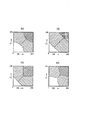
以上のような処理を実行することにより、従来例の図14と同じ閾値処理となる図7(a)で示したような閾値条件処理も、図7(a)で示す閾値条件よりも複雑な閾値条件となる図8(a)に示すような閾値条件処理も、共通の形式をもつ閾値テーブルを定義し、その閾値テーブル中の値を異なるように設定するだけで容易に複雑な閾値設定処理が可能になる。
【0077】
表1は図7(a)に対応する閾値条件をもつ閾値テーブルであり、表2は図8(a)に対応する閾値条件をもつ閾値テーブルである。
【0078】
【表1】
【表2】
【0080】
同様に、図8(a)に示すような閾値条件処理をこの実施形態に従って実行する場合、最初に、ステップS20〜S40では図8(b)に示すような閾値条件処理が実行され、次に、ステップS50〜S70では図8(c)に示すような閾値条件処理が実行される。
【0081】
従って以上説明した実施形態に従えば、所定の形式の閾値テーブルを用いて閾値条件処理を行なうので、例えば、図9に示すように、閾値条件が複雑でも、処理を複雑にすることなく容易に行うことができ、また処理が簡単であるゆえに複雑な閾値条件処理も高速に行うことができる。
【0082】
[第2実施形態]
第1実施形態では誤差拡散処理によって多値濃度データを2値化する場合を扱ったが、この実施形態では、誤差拡散処理によって多値濃度データを3値化する場合を扱う。
【0083】
図10はこの実施形態に従う画像形成制御について示すフローチャートである。
【0084】
以下、このフローチャートを参照してこの実施形態の特徴を説明する。
【0085】
まず、ステップS100では従来例のように注目画素のC成分とM成分夫々の濃度値Ct、Mtを求める。次に、ステップS110では、求められたM成分の濃度値Mtに基づいて、C成分の誤差拡散で用いる2つの閾値(Cthreshold1とCthreshold2)を求める。具体的には、この実施形態では、表3〜表6に示すような閾値テーブルをホスト装置52のHDD2002或いはDRAM1003に設定しておき、この閾値テーブルを参照することでその閾値を決定する。
【0086】
ステップS120では、ステップS110で求められた1つの閾値(Cthreshold1)と注目画素の濃度値Ctとを比較する。ここで、Ct≧Cthreshold1であれば処理はステップS130に進み、さらに、ステップS110で求められたもう1つの閾値(Cthreshold2)と注目画素の濃度値Ctとを比較する。ここで、Ct≧Cthreshold2であれば処理はステップS140に進み、Cインクを用いて大きなインク液滴を吐出して記録を行うように設定する。その後、処理はステップS160に進む。これに対して、Ct<Cthreshold2であれば、処理はステップS150に進み、Cインクを用いて小さなインク液滴を吐出して記録を行うように設定する。その後、処理はステップS160に進む。
【0087】
また、ステップS120において、Ct<Cthreshold1であれば、処理はステップS130〜S150をスキップしてステップS160に進む。
【0088】
さて、ステップS160では求められたC成分の濃度値Ctに基づいて、M成分の誤差拡散で用いる2つの閾値(Mthreshold1とMthreshold2)を求める。具体的には、この実施形態では、表3〜表6に示すような閾値テーブルをホスト装置52のHDD2002或いはDRAM1003に設定しておき、この閾値テーブルを参照することでその閾値を決定する。
【0089】
従って、この実施形態では表3〜表6に示す閾値テーブルはC成分とM成分に対して共通に用いられることになる。
【0090】
ステップS170では、ステップS160で求められた1つの閾値(Mthreshold1)と注目画素の濃度値Mtとを比較する。ここで、Mt≧Mthreshold1であれば処理はステップS180に進み、さらに、ステップS160で求められたもう1つの閾値(Mthreshold2)と注目画素の濃度値Mtとを比較する。ここで、Mt≧Mthreshold2であれば処理はステップS190に進み、Mインクを用いて大きなインク液滴を吐出して記録を行うように設定する。その後、処理は終了する。これに対して、Mt<Mthreshold2であれば、処理はステップS200に進み、Mインクを用いて小さなインク液滴を吐出して記録を行うように設定する。その後、処理は終了する。
【0091】
これに対して、ステップS170において、Mt<Mthreshold1であれば、処理はステップS180〜S200をスキップして処理を終了する。
【0092】
以上のような処理を実行することにより、図11(a)で示したような閾値条件処理も図12(a)に示すような閾値条件処理も、共通の形式をもつ閾値テーブルを定義し、その閾値テーブル中の値を異なるように設定するだけで容易に複雑な閾値設定処理が可能になる。
【0093】
表3と表4とは図11(a)に対応する閾値条件をもつ閾値テーブルであり、表5と表6とは図12(a)に対応する閾値条件をもつ閾値テーブルである。
【0094】
【表3】
【表4】
【表5】
【表6】
【0098】
同様に、図12(a)に示すような閾値条件処理をこの実施形態に従って実行する場合、最初に、ステップS110〜S150では図12(b)に示すような閾値条件処理が実行され、次に、ステップS160〜S200では図12(c)に示すような閾値条件処理が実行される。特に、図12に示す閾値条件は中間調画像の一様性を改善するために有効なものである。
【0099】
従って以上説明した実施形態に従えば、多値画像データを3値化する場合でも所定の形式の閾値テーブルを用いて閾値条件処理を行なうので、閾値条件が複雑でも、処理を複雑にすることなく容易に行うことができ、また処理が簡単であるゆえに複雑な閾値条件処理も高速に行うことができる。
【0100】
なお、この実施形態では、3値化のみを扱ったが、画像出力装置であるインクジェットプリンタがドロップ変調と同色系の濃度の異なるインク(例えば、淡シアンインク、濃シアンインク、淡マゼンタインク、濃マゼンタインク)を用いることによって4値化や5値化などに対応可能である場合には、4値化、5値化などの多値の誤差拡散処理を行なうための閾値テーブルを作成しても良いことは言うまでもない。
【0101】
[第3実施形態]
第1、第2実施形態では誤差拡散処理によって多値濃度データの内、C成分とM成分とを扱った場合について説明したが、この実施形態では、これらの成分に加えてK成分も扱う。
【0102】
図13はこの実施形態に従う画像形成制御について示すフローチャートである。
【0103】
以下、このフローチャートを参照してこの実施形態の特徴を説明する。
【0104】
まず、ステップS210では注目画素のC成分とM成分とK成分夫々の濃度値Ct、Mt、Ktを求める。次に、ステップS220では、求められたM成分の濃度値MtとK成分の濃度値Ctに基づいて、C成分の誤差拡散で用いる閾値(Cthreshold)を求める。具体的には、この実施形態では、表7に示すような閾値テーブルをホスト装置52のHDD2002或いはDRAM1003に設定しておき、この閾値テーブルを参照することでその閾値を決定する。
【0105】
ステップS230では、ステップS220で求められた閾値(Cthreshold)と注目画素の濃度値Ctとを比較する。ここで、Ct≧Cthresholdであれば処理はステップS240に進み、Cインクで記録を行うように設定する。その後、処理はステップS250に進む。これに対して、Ct<Cthresholdであれば、処理はステップS240をスキップしてステップS250に進む。
【0106】
さて、ステップS250では求められたC成分の濃度値CtとK成分の濃度値Ktとに基づいて、M成分の誤差拡散で用いる閾値(Mthreshold)を求める。具体的には、この実施形態では、表7に示すような閾値テーブルをホスト装置52のHDD2002或いはDRAM1003に設定しておき、この閾値テーブルを参照することでその閾値を決定する。
【0107】
ステップS260では、ステップS250で求められた閾値(Mthreshold)と注目画素の濃度値Mtとを比較する。ここで、Mt≧Mthresholdであれば処理はステップS270に進み、Mインクで記録を行うように設定する。その後、処理はステップS280に進む。これに対して、Mt<Mthresholdであれば、処理はステップS270をスキップしてステップS280に進む。
【0108】
さらに、ステップS280では求められたC成分の濃度値CtとM成分の濃度値Mtとに基づいて、K成分の誤差拡散で用いる閾値(Kthreshold)を求める。具体的には、この実施形態では、表7に示すような閾値テーブルをホスト装置52のHDD2002或いはDRAM1003に設定しておき、この閾値テーブルを参照することでその閾値を決定する。
【0109】
従って、この実施形態では表7に示す閾値テーブルはC成分とM成分とK成分とに対して共通に用いられることになる。
【0110】
ステップS290では、ステップS280で求められた閾値(Kthreshold)と注目画素の濃度値Ktとを比較する。ここで、Kt≧Kthresholdであれば処理はステップS300に進み、Kインクで記録を行うように設定する。その後、処理は終了する。これに対して、Kt<Kthresholdであれば、処理はステップS300をスキップして終了する。
【0111】
以上の処理のコアの部分をコードで表現すると以下のようになる。
【0112】
【0113】
表7はCMK成分共通に用いる閾値テーブルである。
【0114】
【表7】
【0115】
さらに、この実施形態を第2実施形態で説明した3値化の処理と組み合わせすることで処理の単純化と処理高速化の利点は更に大きくなる。
【0116】
なお、本発明は前述の実施形態で説明した閾値テーブルによって限定されるものではない。閾値テーブルの形式は保持しながら、そのテーブルに設定される値を異ならせることで、例えば、以下に示すような種々の閾値条件での処理が可能になる。
【0117】
(1)C成分とM成分の濃度値の和(C+M)ではなく、図9(a)に示すようにC成分とM成分の濃度値夫々の二乗和(C2+M2)のような閾値条件を用いる。表8はこのときに用いる閾値テーブルである。
【0118】
【表8】
【0119】
(2)図9(b)に示すように、 閾値にノイズを重畳させた閾値条件を用いる。表9はこのときに用いる閾値テーブルである。
【0120】
【表9】
このような閾値条件を用いることで、CインクもしくはMインクによるドットが連続して形成される可能性を低減する事が出来る。
【0122】
(3)図9(c)に示すように、ハイライト部と中間調から高濃度領域での誤差拡散の傾向を変化させる。このような閾値条件を用いることで、中間調領域におけるインクドットの付着位置の乱れによる画質劣化を低減することができる。
【0123】
(4)図9(d)に示すように、閾値境界をできるだけなだらかにする。このような閾値条件を用いることで、閾値境界付近におけるCインクとMインクの排他的使用をする領域とそうではない領域との間の急峻な変化を減らすことができ実際の画像の表現力を向上させることができる。
【0124】
このように、閾値テーブルを用いることで閾値条件処理に柔軟性が加わることになる。このような閾値テーブルを、例えば、インクジェットプリンタにおける実際のインク吐出量やインクの組成と組み合わせで用いることで、画像形成処理内容や処理目的を容易に変更できる。
【0125】
さて、以上の実施形態においては、記録ヘッドから吐出される液滴はインクであるとして説明し、さらにインクタンクに収容される液体はインクであるとして説明したが、その収容物はインクに限定されるものではない。例えば、記録画像の定着性や耐水性を高めたり、その画像品質を高めたりするために記録媒体に対して吐出される処理液のようなものがインクタンクに収容されていても良い。
【0126】
以上の実施形態は、特にインクジェット記録方式の中でも、インク吐出を行わせるために利用されるエネルギーとして熱エネルギーを発生する手段(例えば電気熱変換体やレーザ光等)を備え、前記熱エネルギーによりインクの状態変化を生起させる方式を用いることにより記録の高密度化、高精細化が達成できる。
【0127】
その代表的な構成や原理については、例えば、米国特許第4723129号明細書、同第4740796号明細書に開示されている基本的な原理を用いて行うものが好ましい。この方式はいわゆるオンデマンド型、コンティニュアス型のいずれにも適用可能であるが、特に、オンデマンド型の場合には、液体(インク)が保持されているシートや液路に対応して配置されている電気熱変換体に、記録情報に対応していて核沸騰を越える急速な温度上昇を与える少なくとも1つの駆動信号を印加することによって、電気熱変換体に熱エネルギーを発生せしめ、記録ヘッドの熱作用面に膜沸騰を生じさせて、結果的にこの駆動信号に1対1で対応した液体(インク)内の気泡を形成できるので有効である。この気泡の成長、収縮により吐出用開口を介して液体(インク)を吐出させて、少なくとも1つの滴を形成する。この駆動信号をパルス形状をすると、即時適切に気泡の成長収縮が行われるので、特に応答性に優れた液体(インク)の吐出が達成でき、より好ましい。
【0128】
このパルス形状の駆動信号としては、米国特許第4463359号明細書、同第4345262号明細書に記載されているようなものが適している。なお、上記熱作用面の温度上昇率に関する発明の米国特許第4313124号明細書に記載されている条件を採用すると、さらに優れた記録を行うことができる。
【0129】
記録ヘッドの構成としては、上述の各明細書に開示されているような吐出口、液路、電気熱変換体の組み合わせ構成(直線状液流路または直角液流路)の他に熱作用面が屈曲する領域に配置されている構成を開示する米国特許第4558333号明細書、米国特許第4459600号明細書を用いた構成も本発明に含まれるものである。加えて、複数の電気熱変換体に対して、共通するスロットを電気熱変換体の吐出部とする構成を開示する特開昭59−123670号公報や熱エネルギーの圧力波を吸収する開口を吐出部に対応させる構成を開示する特開昭59−138461号公報に基づいた構成としても良い。
【0130】
さらに、記録装置が記録できる最大記録媒体の幅に対応した長さを有するフルラインタイプの記録ヘッドとしては、上述した明細書に開示されているような複数記録ヘッドの組み合わせによってその長さを満たす構成や、一体的に形成された1個の記録ヘッドとしての構成のいずれでもよい。
【0131】
加えて、上記の実施形態で説明した記録ヘッド自体に一体的にインクタンクが設けられたカートリッジタイプの記録ヘッドのみならず、装置本体に装着されることで、装置本体との電気的な接続や装置本体からのインクの供給が可能になる交換自在のチップタイプの記録ヘッドを用いてもよい。
【0132】
また、以上説明した記録装置の構成に、記録ヘッドに対する回復手段、予備的な手段等を付加することは記録動作を一層安定にできるので好ましいものである。これらを具体的に挙げれば、記録ヘッドに対してのキャッピング手段、クリーニング手段、加圧あるいは吸引手段、電気熱変換体あるいはこれとは別の加熱素子あるいはこれらの組み合わせによる予備加熱手段などがある。また、記録とは別の吐出を行う予備吐出モードを備えることも安定した記録を行うために有効である。
【0133】
さらに、記録装置の記録モードとしては黒色等の主流色のみの記録モードだけではなく、記録ヘッドを一体的に構成するか複数個の組み合わせによってでも良いが、異なる色の複色カラー、または混色によるフルカラーの少なくとも1つを備えた装置とすることもできる。
【0134】
以上説明した実施の形態においては、インクが液体であることを前提として説明しているが、室温やそれ以下で固化するインクであっても、室温で軟化もしくは液化するものを用いても良く、あるいはインクジェット方式ではインク自体を30°C以上70°C以下の範囲内で温度調整を行ってインクの粘性を安定吐出範囲にあるように温度制御するものが一般的であるから、使用記録信号付与時にインクが液状をなすものであればよい。
【0135】
加えて、積極的に熱エネルギーによる昇温をインクの固形状態から液体状態への状態変化のエネルギーとして使用せしめることで積極的に防止するため、またはインクの蒸発を防止するため、放置状態で固化し加熱によって液化するインクを用いても良い。いずれにしても熱エネルギーの記録信号に応じた付与によってインクが液化し、液状インクが吐出されるものや、記録媒体に到達する時点では既に固化し始めるもの等のような、熱エネルギーの付与によって初めて液化する性質のインクを使用する場合も本発明は適用可能である。このような場合インクは、特開昭54−56847号公報あるいは特開昭60−71260号公報に記載されるような、多孔質シート凹部または貫通孔に液状または固形物として保持された状態で、電気熱変換体に対して対向するような形態としてもよい。本発明においては、上述した各インクに対して最も有効なものは、上述した膜沸騰方式を実行するものである。
【0136】
さらに加えて、本発明に係る記録装置の形態としては、コンピュータ等の情報処理機器の画像出力端末として一体または別体に設けられるものの他、リーダ等と組み合わせた複写装置、さらには送受信機能を有するファクシミリ装置の形態を取るものであっても良い。
【0137】
なお、本発明は、複数の機器(例えばホストコンピュータ、インタフェース機器、リーダ、プリンタなど)から構成されるシステムに適用しても、一つの機器からなる装置(例えば、複写機、ファクシミリ装置など)に適用してもよい。
【0138】
また、本発明の目的は、前述した実施形態の機能を実現するソフトウェアのプログラムコードを記録した記憶媒体(または記録媒体)を、システムあるいは装置に供給し、そのシステムあるいは装置のコンピュータ(またはCPUやMPU)が記憶媒体に格納されたプログラムコードを読み出し実行することによっても、達成されることは言うまでもない。この場合、記憶媒体から読み出されたプログラムコード自体が前述した実施形態の機能を実現することになり、そのプログラムコードを記憶した記憶媒体は本発明を構成することになる。また、コンピュータが読み出したプログラムコードを実行することにより、前述した実施形態の機能が実現されるだけでなく、そのプログラムコードの指示に基づき、コンピュータ上で稼働しているオペレーティングシステム(OS)などが実際の処理の一部または全部を行い、その処理によって前述した実施形態の機能が実現される場合も含まれることは言うまでもない。
【0139】
さらに、記憶媒体から読み出されたプログラムコードが、コンピュータに挿入された機能拡張カードやコンピュータに接続された機能拡張ユニットに備わるメモリに書込まれた後、そのプログラムコードの指示に基づき、その機能拡張カードや機能拡張ユニットに備わるCPUなどが実際の処理の一部または全部を行い、その処理によって前述した実施形態の機能が実現される場合も含まれることは言うまでもない。
【0140】
【発明の効果】
以上説明したように本発明によれば、他の色成分の値を考慮して誤差拡散処理を行なうので、他の成分との重なり合いを考慮した画像形成が可能になり、高品位な画像を形成することができるという効果がある。
【0141】
また、請求項2、4、12、及び14に記載の発明によれば、誤差拡散処理に用いる閾値決定をテーブルを用いて行うので、より複雑な閾値条件処理を簡単に行って高速に誤差拡散処理を行なうことが可能になる。
【図面の簡単な説明】
【図1】本発明の共通実施形態に係る情報処理システムの概略構成を示すブロック図である。
【図2】情報処理システムを構成するホスト装置51と画像出力装置52のハードウェア構成概要を示すブロック図である。
【図3】画像出力装置52の代表的な実施形態であるインクジェットプリンタIJRAの構成の概要を示す外観斜視図である。
【図4】情報処理システムで用いられるソフトウェアの構造を示すブロック図である。
【図5】画像処理概要を示すフローチャートである。
【図6】第1実施形態に従う画像形成制御について示すフローチャートである。
【図7】第1実施形態で用いる閾値条件を示す図である。
【図8】第1実施形態で用いる別の閾値条件を示す図である。
【図9】適用可能な種々の閾値条件の例を示す図である。
【図10】第2実施形態に従う画像形成制御について示すフローチャートである。
【図11】第2実施形態で用いる閾値条件を示す図である。
【図12】第2実施形態で用いる別の閾値条件を示す図である。
【図13】第3実施形態に従う画像形成制御について示すフローチャートである。
【図14】従来のインクジェット方式に従う画像形成制御を示す図である。
【符号の説明】
11 アプリケーションソフトウェア
21 描画処理インタフェース
22 スプーラ
31−1、31−2、……、31−n 装置固有描画機能
33 色特性変換
34 中間調処理(ハーフトーニング)
35 プリントコマンド生成
51 ホスト装置
52 画像出力装置
53 双方向インタフェース
54 ドライバソフトウェア
1000 処理部
1001 MPU
1002 バス
1003 DRAM
1004 ブリッジ
1005 グラフィックアダプタ
1006 HDDコントローラ
1007 キーボードコントローラ
1008 通信I/F
2001 表示装置
2002 HDD装置
2003 キーボード
3001 MCU
3003 制御回路部
3004 ROM
3005 DRAM
3006 通信I/F
3007 ヘッドドライバ
3008 CRモータドライバ
3009 LFモータドライバ
3010 記録ヘッド
3011 キャリア(CR)モータ
3012 搬送モータ[0001]
BACKGROUND OF THE INVENTION
The present invention relates to an image processing apparatus and an image processing method, and more particularly to an image processing apparatus and an image processing method for performing pseudo-halftone processing by performing error diffusion processing on multi-value image density data.
[0002]
[Prior art]
Conventionally, an error diffusion method is known as pseudo gradation processing for expressing a multi-valued image in binary ("An Adaptive Algorithm for Spatial Gray Scale" in society for Information Display 1975 Symposium Digest of Technical Papers, 1975, 36). . In this method, if the pixel of interest is P, its density is v, and the surrounding pixels P0, P1, P2, and P3 of the pixel of interest P are v0, v1, v2, v3, and the threshold for binarization is T. The binarization error E at the target pixel P is distributed to the peripheral pixels P0, P1, P2, and P3 by weight coefficients W0, W1, W2, and W3 that are empirically obtained, and the average density is macroscopically equal to the density of the original image. It is a method to do.
[0003]
For example, if the output binary data is o
If v ≥ T, then o = 1, E = v-Vmax; . . . (1)
If v <T, o = 0, E = v-Vmin;
(However, Vmax: Maximum concentration, Vmin: Minimum concentration)
v0 = v0 + E × W0; . . . (2)
v1 = v1 + E × W1; . . . (3)
v2 = v2 + E × W2; . . . (4)
v3 = v3 + E × W3; . . . (5)
(Examples of weighting factors: W0 = 7/16, W1 = 1/16, W2 = 5/16, W3 = 3/16)
It can be expressed as.
[0004]
Conventionally, when a multi-value image is output using, for example, a color ink jet printer, cyan (C), magenta (M), yellow (Y), and black (K) inks, error diffusion is performed independently for each color. Since pseudo gradation processing is performed using a method or the like, when one color is viewed, even if the visual characteristics are excellent, good visual characteristics cannot always be obtained when two or more colors overlap.
[0005]
In order to improve this problem, Japanese Patent Application Laid-Open No. 8-279920 and Japanese Patent Application Laid-Open No. 11-10918 are good even when two or more colors are overlapped by combining two or more colors and using an error diffusion method. Disclosed is a pseudo halftone processing method capable of obtaining excellent visual characteristics.
[0006]
Japanese Laid-Open Patent Publication No. 9-139841 discloses a method of performing similar improvements by correcting the output value by the sum of input values after performing pseudo-middle gradation processing for two or more colors independently. Yes.
[0007]
In particular, it is effective to form an image so that the dots of the cyan component (C) and the magenta component (M) do not overlap each other in order to reduce the graininess in the middle density region of the color image. The following methods are used.
[0008]
FIG. 14 is a diagram showing image formation control according to a conventional ink jet system.
[0009]
Here, the image data will be described on the assumption that the density component (YMCK) of each pixel is expressed by multi-value data having 8 bits (gradation value of 0 to 255).
[0010]
If the C component and M component density Ct, Mt of the target pixel of the multi-valued color image are C and M, respectively,
Ct = C + Cerr
Mt = M + Merr
It is expressed. Here, Cerr and Merr are values obtained by error diffusion with respect to the pixel of interest for each of the C component and the M component.
[0011]
As shown in FIG. 14, regarding C and M image formation, four types of image formation control are performed according to the density of the C component and M component of the target pixel.
1. If the sum of (Ct + Mt) is equal to or less than the threshold (Threshold 1), that is, belongs to the region (1) in FIG. 14, dot recording is not performed using C ink or M ink.
2. The sum of (Ct + Mt) exceeds the threshold (Threshold 1), the sum of (Ct + Mt) is less than another threshold (Threshold 2), and Ct> Mt, that is, the region (FIG. If it belongs to 2), dot recording is performed only with C ink.
3. The sum of (Ct + Mt) exceeds the threshold (Threshold 1), the sum of (Ct + Mt) is less than another threshold (Threshold 2), and Ct ≦ Mt, that is, the region (FIG. If it belongs to 3), dot recording is performed only with M ink.
4). If the sum of (Ct + Mt) is greater than or equal to another threshold (Threshold 2), that is, belongs to the region (4) in FIG. 14, dot recording is performed using C ink and M ink.
[0012]
Here,
[0013]
[Problems to be solved by the invention]
However, in the above conventional example, since the image forming method for the C component and the M component is changed based on the sum of the density values of the C component and the M component, only simple image formation control can be performed. When there are adjacent pixels whose target image data fluctuates before and after the threshold, pixels in which overlap of C ink and M ink occurs in the narrow area and pixels that do not exist are mixed. However, the quality of the formed image is deteriorated.
[0014]
In order to prevent such a situation, it is only necessary to perform more complicated threshold division. However, if this is done, it is necessary to make the threshold condition processing more complicated, and the processing time may be longer. Inevitable.
[0015]
Furthermore, the threshold value processing must be simplified in the conventional processing based on the sum of the density values of the C component and the M component, and there is a problem that it is difficult to perform processing with high flexibility.
[0016]
Further, if exclusive error diffusion is performed using the sum of the three components in addition to the black (K) component, for example, a very complicated process such as the following code is required.
[0017]
[0018]
[Means for Solving the Problems]
In order to achieve the above object, an image processing apparatus of the present invention has the following configuration.
[0019]
That is, an image processing apparatus for outputting a result of said error diffusion processing by performing error diffusion processing on multivalued image data comprising a plurality of color components, the plurality of color components, the error in the first color component In executing the diffusion process, a first determination unit that determines a threshold value used in the error diffusion process based on the density value of the second color component, and the first threshold value based on the threshold value determined by the first determination unit. First error diffusion execution means for executing error diffusion processing on the color components of the first color , first output means for outputting an execution result by the first error diffusion execution means, and second color components among the plurality of color components In executing the error diffusion processing, the second determination means for determining the threshold value used for the error diffusion processing based on the density value of the first color component, and the threshold value determined by the second determination means. the second color component An image processing apparatus characterized by comprising a second error diffusion execution means for executing an error diffusion process regarding, and a second output means for outputting the execution result by said second error diffusion execution means.
[0020]
It is preferable that the first and second determining means use a table that defines a relationship between a density value and a threshold value for determining the threshold value.
[0021]
Each of the first and second determining means may determine a plurality of threshold values for binarization as well as binarization. In that case, the first and second determination means may use a plurality of tables for determining each of the plurality of threshold values.
[0022]
Furthermore, among the plurality of color components, when performing error diffusion processing on a third color component, the density value of the second color component and the first color component threshold used in said error diffusion processing Third determination means for determining based on the sum, third error diffusion execution means for executing error diffusion processing on the third color component based on the threshold value determined by the third determination means, and the third error You may provide the 3rd output means which outputs the execution result by a spreading | diffusion execution means.
[0023]
As described above, when the error diffusion process is performed on the first, second, and third color components, the first determining unit determines the density value of the second color component and the third color component. Based on the sum of the density values, a threshold value used for the error diffusion process relating to the first color component is determined, and the second determination means is configured to determine the density value of the first color component and the density value of the third color component. Based on the sum, the threshold value used for the error diffusion process for the second color component may be determined.
[0024]
Now, the plurality of color components, yellow component, magenta component, a cyan component, and a black component, the first color component is cyan component, the second color component is magenta component, a third color The component is a black component.
[0025]
Furthermore, it is desirable to provide image forming means such as an ink jet printer for inputting an error diffusion processing execution result output from the first, second and third output means to form an image.
[0026]
The ink jet printer preferably includes an ink jet recording head that ejects ink using thermal energy, and the ink jet recording head preferably includes an electrothermal transducer for generating thermal energy applied to the ink.
[0027]
According to another aspect of the present invention, there is provided an image processing method by performing error diffusion processing on multivalued image data comprising a plurality of color components and outputs the result of the error diffusion processing, the plurality of color components, the In executing error diffusion processing for one color component, a first determination step for determining a threshold value used for the error diffusion processing based on the density value of the second color component, and the threshold value determined in the first determination step A first error diffusion execution step for performing error diffusion processing on the first color component based on the first color component, a first output step for outputting an execution result in the first error diffusion execution step, and among the plurality of color components In performing the error diffusion process on the second color component, the threshold value used for the error diffusion process is determined based on the density value of the first color component, and is determined in the second determination step. Based on threshold A second error diffusion execution step of executing the error diffusion processing on said second color component, the image processing method characterized by a second output step of outputting the execution result in said second error diffusion execution step Prepare.
[0028]
According to still another invention, a computer-readable storage medium storing a program for executing the above image processing method is provided.
[0029]
The present invention is the above-described configuration, when outputting the result by performing error diffusion processing on multivalued image data comprising a plurality of color components, among the plurality of color components, the error diffusion processing on a first color component Upon executing, the thresholds used in the error diffusion processing is determined based on the concentration value of the second color component, it performs the error diffusion processing on a first color component based on the determined threshold, the execution result outputs a, among the plurality of color components, when performing the error diffusion processing in the second color component, determined on the basis of the threshold value used in the error diffusion processing to the density value of the first color component, the decision Based on the threshold value, an error diffusion process is executed for the second color component, and the execution result is output.
[0030]
DETAILED DESCRIPTION OF THE INVENTION
Preferred embodiments of the present invention will be described below in detail with reference to the accompanying drawings.
[0031]
[Common embodiment]
First, an overall overview of an information processing system, a hardware configuration overview, a software configuration overview, and an image processing overview that are commonly used in the following embodiments will be described.
[0032]
FIG. 1 is a block diagram showing a schematic configuration of an information processing system according to a common embodiment of the present invention.
[0033]
As shown in FIG. 1, the information processing system includes a
[0034]
1. Hardware Configuration of
[0035]
FIG. 2 is a block diagram showing an outline of the hardware configuration of the
[0036]
As shown in FIG. 2, the
[0037]
The
[0038]
Further, the
[0039]
Furthermore, a display device 2001 (CRT in this example) that displays graphic information and the like to the operator is connected to the
[0040]
On the other hand, the
[0041]
The
[0042]
Further, the
[0043]
Next, a specific configuration of the
[0044]
FIG. 3 is an external perspective view showing an outline of the configuration of an ink jet printer IJRA which is a typical embodiment of the
[0045]
In FIG. 3, the carriage HC engaged with the spiral groove 5004 of the
[0046]
These capping, cleaning, and suction recovery are configured so that desired processing can be performed at their corresponding positions by the action of the
[0047]
As described above, the ink tank IT and the recording head IJH may be integrally formed to constitute a replaceable ink cartridge IJC. However, the ink tank IT and the recording head IJH can be separated from each other. Then, only the ink tank IT may be exchanged when the ink runs out.
[0048]
Further, the control circuit unit referred to in FIG. 2 is built in the ink jet printer IJRA.
[0049]
The recording head IJH records a color image using at least four inks of yellow (Y), magenta (M), cyan (C), and black (K) based on multi-value density data of each component of YMCK. Can do.
[0050]
2. Outline of Software Configuration and Outline of Image Processing FIG. 4 is a block diagram showing the structure of software used in the information processing system described above.
[0051]
As can be seen from FIG. 4, in order to output the recording data to the
[0052]
In this embodiment, the parts that depend on each of the image output apparatuses are handled by the apparatus-specific drawing functions 31-1, 31-2, ..., 31-n, and are program components that depend on the individual implementation of the image processing apparatus. Are separated from a program that can perform processing in common, and the fundamental processing portion of the driver software has a structure independent of individual image output apparatuses.
[0053]
The line-divided image converted into the quantized amount is subjected to image processing such as color
[0054]
As shown in FIG. 4, application software 11 is provided in the application software layer, and a
[0055]
The driver software hierarchy receives device-specific rendering functions 31-1, 31-2,..., 31-n in which representation formats unique to the image output device are stored, and line-divided image information from the OS. A color
[0056]
Next, the case where the application software outputs an image to the
[0057]
When the application software 11 outputs an image to the
[0058]
When drawing commands constituting the screen / paper surface are completed (step S2), the OS calls each of the drawing commands while calling the device-specific drawing functions 31-1, 31-2, ..., 31-n in the driver software. Is converted to a device-specific representation format (each drawing unit is divided into lines) (step S3), and then the screen / paper is line-divided into image information and passed to the driver software (step S4).
[0059]
Inside the driver software, the color
[0060]
Details of the halftoning will be described in each embodiment described later.
[0061]
The print
[0062]
Thereafter, the print
[0063]
In this embodiment, the above control method can be realized by storing and operating the program according to the flowchart of FIG. 5 in the storage device in the
[0064]
As described above, the basic processing part of the driver software is structured independently of the individual image output device, so that the data processing between the driver software and the image output device can be flexibly assigned without damaging the configuration of the driver software. It becomes possible to make changes, which is advantageous in terms of software maintenance and management.
[0065]
Next, several embodiments using the system according to the common embodiment described above will be described. In the following embodiments, details of error diffusion processing executed by the
[0066]
The error diffusion processing described below is density data in which each pixel is composed of a yellow (Y) component, a magenta (M) component, a cyan (C) component, and a black (K) component, and each component has 8 bits ( It is assumed that multivalued image data composed of (256 gradation expression) is used.
[0067]
[First embodiment]
Here, unlike the conventional example, an error diffusion process capable of complicated threshold condition processing will be described. The target of error diffusion processing according to this embodiment is multi-value image data of C component and M component.
[0068]
In this embodiment, the case where the multi-value density data is binarized by error diffusion processing is handled.
[0069]
FIG. 6 is a flowchart showing image formation control according to this embodiment.
[0070]
The features of this embodiment will be described below with reference to this flowchart.
[0071]
First, in step S10, the density values Ct and Mt of the C component and M component of the target pixel are obtained as in the conventional example. In step S20, a threshold (Cthreshold) used for error diffusion of the C component is obtained based on the obtained density value Mt of the M component. Specifically, in this embodiment, a threshold table as shown in Table 1 and Table 2 is set in the
[0072]
In step S30, the threshold (Cthreshold) obtained in step S20 is compared with the density value Ct of the target pixel. Here, if Ct ≧ Cthreshold, the process proceeds to step S40, and the recording is set to be performed with C ink. Thereafter, the process proceeds to step S50. On the other hand, if Ct <Cthreshold, the process skips step S40 and proceeds to step S50.
[0073]
In step S50, a threshold (Mthreshold) used for error diffusion of the M component is obtained based on the obtained C component density value Ct. Specifically, in this embodiment, a threshold table as shown in Table 1 and Table 2 is set in the
[0074]
Therefore, in this embodiment, the threshold tables shown in Table 1 and Table 2 are used in common for the C component and the M component.
[0075]
In step S60, the threshold (Mthreshold) obtained in step S50 is compared with the density value Mt of the target pixel. Here, if Mt ≧ Mthreshold, the process proceeds to step S70, and the recording is set to be performed with M ink. Thereafter, the process proceeds to step S50. On the other hand, if Mt <Mthreshold, the process skips step S70 and ends the process.
[0076]
By executing the processing as described above, the threshold condition processing as shown in FIG. 7A, which is the same threshold processing as in FIG. 14 of the conventional example, is more complicated than the threshold condition shown in FIG. The threshold condition processing as shown in FIG. 8A, which is the threshold condition, is also a complicated threshold setting process simply by defining a threshold table having a common format and setting different values in the threshold table. Is possible.
[0077]
Table 1 is a threshold table having threshold conditions corresponding to FIG. 7A, and Table 2 is a threshold table having threshold conditions corresponding to FIG.
[0078]
[Table 1]
[Table 2]
[0080]
Similarly, when threshold condition processing as shown in FIG. 8A is executed according to this embodiment, first, threshold condition processing as shown in FIG. 8B is executed in steps S20 to S40, and then In steps S50 to S70, threshold condition processing as shown in FIG. 8C is executed.
[0081]
Therefore, according to the embodiment described above, threshold condition processing is performed using a threshold table of a predetermined format. For example, as shown in FIG. 9, even if the threshold conditions are complicated, the processing can be easily performed without complicating the processing. Further, since the processing is simple, complicated threshold condition processing can be performed at high speed.
[0082]
[Second Embodiment]
In the first embodiment, the case where the multi-value density data is binarized by the error diffusion process is dealt with. In this embodiment, the case where the multi-value density data is binarized by the error diffusion process is dealt with.
[0083]
FIG. 10 is a flowchart showing image formation control according to this embodiment.
[0084]
The features of this embodiment will be described below with reference to this flowchart.
[0085]
First, in step S100, the density values Ct and Mt of the C component and M component of the target pixel are obtained as in the conventional example. Next, in step S110, two threshold values (Cthreshold1 and Cthreshold2) used for error diffusion of the C component are obtained based on the obtained density value Mt of the M component. Specifically, in this embodiment, a threshold table as shown in Tables 3 to 6 is set in the
[0086]
In step S120, one threshold value (Cthreshold1) obtained in step S110 is compared with the density value Ct of the target pixel. If Ct ≧ Cthreshold1, the process proceeds to step S130, and the other threshold value (Cthreshold2) obtained in step S110 is compared with the density value Ct of the target pixel. Here, if Ct ≧ Cthreshold2, the process proceeds to step S140, and a setting is made to perform recording by ejecting large ink droplets using C ink. Thereafter, the process proceeds to step S160. On the other hand, if Ct <Cthreshold2, the process proceeds to step S150, and a setting is made to perform recording by ejecting small ink droplets using C ink. Thereafter, the process proceeds to step S160.
[0087]
If Ct <Cthreshold1 in step S120, the process skips steps S130 to S150 and proceeds to step S160.
[0088]
In step S160, two threshold values (Mthreshold1 and Mthreshold2) used for error diffusion of the M component are obtained based on the obtained C component density value Ct. Specifically, in this embodiment, a threshold table as shown in Tables 3 to 6 is set in the
[0089]
Therefore, in this embodiment, the threshold value tables shown in Tables 3 to 6 are commonly used for the C component and the M component.
[0090]
In step S170, one threshold value (Mthreshold1) obtained in step S160 is compared with the density value Mt of the target pixel. If Mt ≧ Mthreshold1, the process proceeds to step S180, and the other threshold value (Mthreshold2) obtained in step S160 is compared with the density value Mt of the target pixel. Here, if Mt ≧ Mthreshold2, the process proceeds to step S190, and a setting is made to perform recording by ejecting large ink droplets using M ink. Thereafter, the process ends. On the other hand, if Mt <Mthreshold2, the process proceeds to step S200, and a setting is made to perform recording by ejecting small ink droplets using M ink. Thereafter, the process ends.
[0091]
On the other hand, if Mt <Mthreshold1 in step S170, the process skips steps S180 to S200 and ends the process.
[0092]
By executing the above process, the threshold condition process as shown in FIG. 11A and the threshold condition process as shown in FIG. 12A define a threshold table having a common format, Complex threshold setting processing can be easily performed only by setting different values in the threshold table.
[0093]
Tables 3 and 4 are threshold tables having threshold conditions corresponding to FIG. 11A, and Tables 5 and 6 are threshold tables having threshold conditions corresponding to FIG.
[0094]
[Table 3]
[Table 4]
[Table 5]
[Table 6]
[0098]
Similarly, when threshold condition processing as shown in FIG. 12A is executed according to this embodiment, first, threshold condition processing as shown in FIG. 12B is executed in steps S110 to S150, and then In steps S160 to S200, threshold condition processing as shown in FIG. In particular, the threshold condition shown in FIG. 12 is effective for improving the uniformity of a halftone image.
[0099]
Therefore, according to the embodiment described above, threshold value condition processing is performed using a threshold table of a predetermined format even when multi-value image data is ternarized, so that even if the threshold condition is complicated, the processing is not complicated. Since it can be easily performed and the processing is simple, complicated threshold condition processing can be performed at high speed.
[0100]
In this embodiment, only ternary processing is dealt with. However, an ink jet printer which is an image output device uses inks having different densities of the same color system as drop modulation (for example, light cyan ink, dark cyan ink, light magenta ink, dark ink). If it is possible to cope with quaternarization or quinarying by using magenta ink), a threshold value table for performing multivalued error diffusion processing such as quaternarization and quinarization may be created. It goes without saying that it is good.
[0101]
[Third embodiment]
In the first and second embodiments, the case where the C component and the M component of the multi-value density data are handled by error diffusion processing has been described. However, in this embodiment, the K component is also handled in addition to these components.
[0102]
FIG. 13 is a flowchart showing image formation control according to this embodiment.
[0103]
The features of this embodiment will be described below with reference to this flowchart.
[0104]
First, in step S210, density values Ct, Mt, and Kt of the C component, M component, and K component of the target pixel are obtained. In step S220, a threshold (Cthreshold) used for error diffusion of the C component is obtained based on the obtained density value Mt of the M component and the density value Ct of the K component. Specifically, in this embodiment, a threshold table as shown in Table 7 is set in the
[0105]
In step S230, the threshold (Cthreshold) obtained in step S220 is compared with the density value Ct of the target pixel. Here, if Ct ≧ Cthreshold, the process proceeds to step S240, and the recording is set to be performed with C ink. Thereafter, the process proceeds to step S250. On the other hand, if Ct <Cthreshold, the process skips step S240 and proceeds to step S250.
[0106]
In step S250, a threshold value (Mthreshold) used for error diffusion of the M component is obtained based on the obtained C component density value Ct and K component density value Kt. Specifically, in this embodiment, a threshold table as shown in Table 7 is set in the
[0107]
In step S260, the threshold (Mthreshold) obtained in step S250 is compared with the density value Mt of the target pixel. Here, if Mt ≧ Mthreshold, the process proceeds to step S270 to set to perform printing with M ink. Thereafter, the process proceeds to step S280. On the other hand, if Mt <Mthreshold, the process skips step S270 and proceeds to step S280.
[0108]
In step S280, a threshold (Kthreshold) used for error diffusion of the K component is obtained based on the obtained C component density value Ct and M component density value Mt. Specifically, in this embodiment, a threshold table as shown in Table 7 is set in the
[0109]
Therefore, in this embodiment, the threshold value table shown in Table 7 is commonly used for the C component, the M component, and the K component.
[0110]
In step S290, the threshold (Kthreshold) obtained in step S280 is compared with the density value Kt of the target pixel. Here, if Kt ≧ Kthreshold, the process proceeds to step S300, and the recording is set to be performed with K ink. Thereafter, the process ends. On the other hand, if Kt <Kthreshold, the process skips step S300 and ends.
[0111]
The core part of the above processing is expressed in code as follows.
[0112]
[0113]
Table 7 is a threshold table used in common with CMK components.
[0114]
[Table 7]
[0115]
Further, by combining this embodiment with the ternary processing described in the second embodiment, the advantages of simplification of processing and speeding up of processing are further increased.
[0116]
The present invention is not limited to the threshold table described in the above embodiment. By maintaining the format of the threshold table and changing the values set in the table, for example, processing under various threshold conditions as shown below becomes possible.
[0117]
(1) Threshold values such as the sum of squares (C 2 + M 2 ) of the C component and M component density values, as shown in FIG. 9A, instead of the sum of the C component and M component density values (C + M) Use conditions. Table 8 is a threshold value table used at this time.
[0118]
[Table 8]
[0119]
(2) As shown in FIG. 9B, a threshold condition in which noise is superimposed on the threshold is used. Table 9 is a threshold value table used at this time.
[0120]
[Table 9]
By using such a threshold condition, it is possible to reduce the possibility that dots of C ink or M ink are continuously formed.
[0122]
(3) As shown in FIG. 9C, the tendency of error diffusion in the high density region is changed from the highlight portion and halftone. By using such a threshold condition, it is possible to reduce image quality deterioration due to disturbance of the ink dot adhesion position in the halftone area.
[0123]
(4) As shown in FIG. 9D, the threshold boundary is made as gentle as possible. By using such a threshold condition, it is possible to reduce a steep change between the area where the C ink and M ink are exclusively used in the vicinity of the threshold boundary and the area where the ink is not, so that the expressive power of the actual image can be reduced. Can be improved.
[0124]
Thus, flexibility is added to threshold condition processing by using the threshold table. By using such a threshold table in combination with, for example, an actual ink discharge amount or ink composition in an ink jet printer, it is possible to easily change the content and purpose of image forming processing.
[0125]
In the above embodiments, the liquid droplets ejected from the recording head have been described as ink, and the liquid stored in the ink tank has been described as ink. However, the container is limited to ink. It is not something. For example, a treatment liquid discharged to the recording medium may be stored in the ink tank in order to improve the fixability and water resistance of the recorded image or to improve the image quality.
[0126]
The above embodiment includes means (for example, an electrothermal converter, a laser beam, etc.) that generates thermal energy as energy used for performing ink discharge, particularly in the ink jet recording system, and the ink is generated by the thermal energy. By using a system that causes a change in the state of recording, it is possible to achieve higher recording density and higher definition.
[0127]
As its typical configuration and principle, for example, those performed using the basic principle disclosed in US Pat. Nos. 4,723,129 and 4,740,796 are preferable. This method can be applied to both the so-called on-demand type and continuous type. In particular, in the case of the on-demand type, it is arranged corresponding to the sheet or liquid path holding the liquid (ink). By applying at least one drive signal corresponding to the recorded information and giving a rapid temperature rise exceeding nucleate boiling to the electrothermal transducer, the thermal energy is generated in the electrothermal transducer, and the recording head This is effective because film boiling occurs on the heat acting surface of the liquid, and as a result, bubbles in the liquid (ink) corresponding to the drive signal on a one-to-one basis can be formed. By the growth and contraction of the bubbles, liquid (ink) is ejected through the ejection opening to form at least one droplet. When the drive signal is pulse-shaped, the bubble growth and contraction is performed immediately and appropriately, and thus it is possible to achieve the discharge of liquid (ink) with particularly excellent responsiveness.
[0128]
As this pulse-shaped drive signal, those described in US Pat. Nos. 4,463,359 and 4,345,262 are suitable. Further excellent recording can be performed by employing the conditions described in US Pat. No. 4,313,124 of the invention relating to the temperature rise rate of the heat acting surface.
[0129]
As the configuration of the recording head, in addition to the combination configuration (straight liquid flow path or right-angle liquid flow path) of the discharge port, the liquid path, and the electrothermal transducer as disclosed in each of the above-mentioned specifications, the heat acting surface The configurations using US Pat. No. 4,558,333 and US Pat. No. 4,459,600, which disclose a configuration in which is disposed in a bending region, are also included in the present invention. In addition, Japanese Patent Application Laid-Open No. 59-123670, which discloses a configuration in which a common slot is used as a discharge portion of an electrothermal transducer, or an opening that absorbs a pressure wave of thermal energy is discharged to a plurality of electrothermal transducers. A configuration based on Japanese Patent Laid-Open No. 59-138461 disclosing a configuration corresponding to each part may be adopted.
[0130]
Furthermore, as a full-line type recording head having a length corresponding to the width of the maximum recording medium that can be recorded by the recording apparatus, the length is satisfied by a combination of a plurality of recording heads as disclosed in the above specification. Either a configuration or a configuration as a single recording head formed integrally may be used.
[0131]
In addition to the cartridge-type recording head in which the ink tank is integrally provided in the recording head itself described in the above embodiment, it can be electrically connected to the apparatus body by being attached to the apparatus body. A replaceable chip type recording head that can supply ink from the apparatus main body may be used.
[0132]
In addition, it is preferable to add recovery means, preliminary means, and the like for the recording head to the configuration of the recording apparatus described above because the recording operation can be further stabilized. Specific examples thereof include a capping unit for the recording head, a cleaning unit, a pressurizing or sucking unit, an electrothermal converter, a heating element different from this, or a preheating unit using a combination thereof. In addition, it is effective to provide a preliminary ejection mode for performing ejection different from recording in order to perform stable recording.
[0133]
Further, the recording mode of the recording apparatus is not limited to the recording mode of only the mainstream color such as black, but the recording head may be integrated or may be a combination of a plurality of colors. An apparatus having at least one of full colors can also be provided.
[0134]
In the embodiment described above, the description is made on the assumption that the ink is a liquid, but it may be an ink that is solidified at room temperature or lower, or an ink that is softened or liquefied at room temperature, Alternatively, the ink jet method generally controls the temperature of the ink so that the viscosity of the ink is within a stable discharge range by adjusting the temperature within a range of 30 ° C. or higher and 70 ° C. or lower. It is sufficient if the ink sometimes forms a liquid.
[0135]
In addition, it is solidified in a stand-by state in order to actively prevent temperature rise by heat energy as energy for changing the state of ink from the solid state to the liquid state, or to prevent ink evaporation. Ink that is liquefied by heating may be used. In any case, by applying heat energy according to the application of thermal energy according to the recording signal, the ink is liquefied and liquid ink is ejected, or when it reaches the recording medium, it already starts to solidify. The present invention can also be applied to the case of using ink having the property of being liquefied for the first time. In such a case, the ink is held as a liquid or solid in a porous sheet recess or through-hole as described in JP-A-54-56847 or JP-A-60-71260, It is good also as a form which opposes with respect to an electrothermal converter. In the present invention, the most effective one for each of the above-described inks is to execute the above-described film boiling method.
[0136]
In addition, as a form of the recording apparatus according to the present invention, a copying apparatus combined with a reader or the like, and a transmission / reception function are provided as an image output terminal of an information processing apparatus such as a computer or the like. It may take the form of a facsimile machine.
[0137]
Note that the present invention can be applied to a system (for example, a copier, a facsimile machine, etc.) consisting of a single device even if it is applied to a system composed of a plurality of devices (for example, a host computer, interface device, reader, printer, etc.). You may apply.
[0138]
Also, an object of the present invention is to supply a storage medium (or recording medium) that records a program code of software that realizes the functions of the above-described embodiments to a system or apparatus, and to perform computer (or CPU or CPU) of the system or apparatus. Needless to say, this can also be achieved when the MPU) reads and executes the program code stored in the storage medium. In this case, the program code itself read from the storage medium realizes the functions of the above-described embodiments, and the storage medium storing the program code constitutes the present invention. Further, by executing the program code read by the computer, not only the functions of the above-described embodiments are realized, but also an operating system (OS) running on the computer based on the instruction of the program code. It goes without saying that a case where the function of the above-described embodiment is realized by performing part or all of the actual processing and the processing is included.
[0139]
Furthermore, after the program code read from the storage medium is written into a memory provided in a function expansion card inserted into the computer or a function expansion unit connected to the computer, the function is based on the instruction of the program code. It goes without saying that the CPU or the like provided in the expansion card or the function expansion unit performs part or all of the actual processing and the functions of the above-described embodiments are realized by the processing.
[0140]
【The invention's effect】
As described above, according to the present invention, since error diffusion processing is performed in consideration of the values of other color components, it is possible to form an image in consideration of overlapping with other components, and form a high-quality image. There is an effect that can be done.
[0141]
According to the invention described in
[Brief description of the drawings]
FIG. 1 is a block diagram showing a schematic configuration of an information processing system according to a common embodiment of the present invention.
FIG. 2 is a block diagram showing an outline of the hardware configuration of a
FIG. 3 is an external perspective view showing an outline of the configuration of an inkjet printer IJRA that is a representative embodiment of the
FIG. 4 is a block diagram showing the structure of software used in the information processing system.
FIG. 5 is a flowchart showing an outline of image processing.
FIG. 6 is a flowchart illustrating image formation control according to the first embodiment.
FIG. 7 is a diagram showing threshold conditions used in the first embodiment.
FIG. 8 is a diagram showing another threshold condition used in the first embodiment.
FIG. 9 is a diagram showing examples of various threshold conditions that can be applied.
FIG. 10 is a flowchart illustrating image formation control according to the second embodiment.
FIG. 11 is a diagram showing threshold conditions used in the second embodiment.
FIG. 12 is a diagram showing another threshold condition used in the second embodiment.
FIG. 13 is a flowchart illustrating image formation control according to the third embodiment.
FIG. 14 is a diagram illustrating image formation control according to a conventional inkjet method.
[Explanation of symbols]
11
35
1002
1004
2001
3003
3005 DRAM
3006 Communication I / F
3007
Claims (17)
前記複数の色成分のうち、第1の色成分に誤差拡散処理を実行するに当たり、該誤差拡散処理に用いる閾値を第2の色成分の濃度値に基づいて決定する第1決定手段と、
前記第1決定手段によって決定された閾値に基づいて前記第1の色成分に関して誤差拡散処理を実行する第1誤差拡散実行手段と、
前記第1誤差拡散実行手段による実行結果を出力する第1出力手段と、
前記複数の色成分のうち、第2の色成分に誤差拡散処理を実行するに当たり、該誤差拡散処理に用いる閾値を第1の色成分の濃度値に基づいて決定する第2決定手段と、
前記第2決定手段によって決定された閾値に基づいて前記第2の色成分に関して誤差拡散処理を実行する第2誤差拡散実行手段と、
前記第2誤差拡散実行手段による実行結果を出力する第2出力手段とを有することを特徴とする画像処理装置。An image processing apparatus that performs error diffusion processing on multi-valued image data composed of a plurality of color components and outputs a result of the error diffusion processing,
Among the plurality of color components, when performing error diffusion processing on a first color component, a first determination means for determining based on a threshold value used for said error diffusion processing to the density value of the second color component,
First error diffusion execution means for executing error diffusion processing on the first color component based on the threshold value determined by the first determination means;
First output means for outputting an execution result by the first error diffusion execution means;
Among the plurality of color components, when performing the error diffusion processing in the second color component, a second determination means for determining based on a threshold value used for said error diffusion processing to the density value of the first color component,
Second error diffusion execution means for executing error diffusion processing on the second color component based on the threshold value determined by the second determination means;
An image processing apparatus comprising: second output means for outputting an execution result by the second error diffusion execution means.
前記第3決定手段によって決定された閾値に基づいて前記第3の色成分に関して誤差拡散処理を実行する第3誤差拡散実行手段と、
前記第3誤差拡散実行手段による実行結果を出力する第3出力手段とをさらに有することを特徴とする請求項1に記載の画像処理装置。Among the plurality of color components, when performing error diffusion processing on a third color component, the sum of the density values of the second color component threshold and the first color component used in said error diffusion processing Third determining means for determining based on;
Third error diffusion execution means for executing error diffusion processing on the third color component based on the threshold value determined by the third determination means;
The image processing apparatus according to claim 1, further comprising a third output unit that outputs an execution result by the third error diffusion execution unit.
前記第1の決定手段は、前記第2の色成分の濃度値と前記第3の色成分の濃度値との和に基づいて、前記第1の色成分に関する誤差拡散処理に用いる閾値を決定し、
前記第2の決定手段は、前記第1の色成分の濃度値と前記第3の色成分の濃度値との和に基づいて、前記第2の色成分に関する誤差拡散処理に用いる閾値を決定することを特徴とする請求項5に記載の画像処理装置。When performing error diffusion processing on the first, second, and third color components,
The first determining means determines a threshold used for error diffusion processing related to the first color component based on the sum of the density value of the second color component and the density value of the third color component. ,
The second determining means determines a threshold value used for error diffusion processing related to the second color component based on the sum of the density value of the first color component and the density value of the third color component. The image processing apparatus according to claim 5.
前記第1の色成分はシアン成分であり、
前記第2の色成分はマゼンタ成分であり、
前記第3の色成分はブラック成分であることを特徴とする請求項1に記載の画像処理装置。The plurality of color components are a yellow component, a magenta component, a cyan component, and a black component,
The first color component is a cyan component;
The second color component is a magenta component;
The image processing apparatus according to claim 1, wherein the third color component is a black component.
前記インクジェット記録ヘッドはインクに与える熱エネルギーを発生するための電気熱変換体を備えていることを特徴とする請求項9に記載の画像処理装置。The inkjet printer includes an inkjet recording head that ejects ink using thermal energy;
The image processing apparatus according to claim 9, wherein the ink jet recording head includes an electrothermal conversion body for generating thermal energy applied to the ink.
前記複数の色成分のうち、第1の色成分に誤差拡散処理を実行するに当たり、該誤差拡散処理に用いる閾値を第2の色成分の濃度値に基づいて決定する第1決定工程と、
前記第1決定工程において決定された閾値に基づいて前記第1の色成分に関して誤差拡散処理を実行する第1誤差拡散実行工程と、
前記第1誤差拡散実行工程における実行結果を出力する第1出力工程と、
前記複数の色成分のうち、第2の色成分に誤差拡散処理を実行するに当たり、該誤差拡散処理に用いる閾値を第1の色成分の濃度値に基づいて決定する第2決定工程と、
前記第2決定工程において決定された閾値に基づいて前記第2の色成分に関して誤差拡散処理を実行する第2誤差拡散実行工程と、
前記第2誤差拡散実行工程における実行結果を出力する第2出力工程とを有することを特徴とする画像処理方法。An image processing method for performing error diffusion processing on multi-value image data composed of a plurality of color components and outputting the result of the error diffusion processing,
Among the plurality of color components, when performing error diffusion processing on a first color component, a first determination step of determining based on a threshold value used for said error diffusion processing to the density value of the second color component,
A first error diffusion execution step of executing error diffusion processing for the first color component based on the threshold value determined in the first determination step;
A first output step for outputting an execution result in the first error diffusion execution step;
Among the plurality of color components, when performing the error diffusion processing in the second color component, a second determination step of determining based on a threshold value used for said error diffusion processing to the density value of the first color component,
A second error diffusion execution step of executing an error diffusion process on the second color component based on the threshold value determined in the second determination step;
An image processing method comprising: a second output step of outputting an execution result in the second error diffusion execution step.
前記第3決定工程において決定された閾値に基づいて前記第3の色成分に関して誤差拡散処理を実行する第3誤差拡散実行工程と、
前記第3誤差拡散実行工程における実行結果を出力する第3出力工程とをさらに有することを特徴とする請求項11に記載の画像処理方法。Among the plurality of color components, when performing error diffusion processing on a third color component, the sum of the density values of the second color component threshold and the first color component used in said error diffusion processing A third determination step based on the determination;
A third error diffusion execution step of executing error diffusion processing for the third color component based on the threshold value determined in the third determination step;
The image processing method according to claim 11, further comprising a third output step of outputting an execution result in the third error diffusion execution step.
前記第1の決定工程は、前記第2の色成分の濃度値と前記第3の色成分の濃度値との和に基づいて、前記第1の色成分に関する誤差拡散処理に用いる閾値を決定し、
前記第2の決定工程は、前記第1の色成分の濃度値と前記第3の色成分の濃度値との和に基づいて、前記第2の色成分に関する誤差拡散処理に用いる閾値を決定することを特徴とする請求項15に記載の画像処理方法。When performing error diffusion processing on the first, second, and third color components,
The first determining step determines a threshold value used for error diffusion processing related to the first color component based on a sum of the density value of the second color component and the density value of the third color component. ,
The second determining step determines a threshold used for error diffusion processing related to the second color component based on the sum of the density value of the first color component and the density value of the third color component. The image processing method according to claim 15.
Priority Applications (10)
| Application Number | Priority Date | Filing Date | Title |
|---|---|---|---|
| JP2000364629A JP4463970B2 (en) | 2000-11-30 | 2000-11-30 | Image processing apparatus and image processing method |
| US09/993,641 US7099046B2 (en) | 2000-11-30 | 2001-11-27 | Image processing apparatus and image processing method |
| DE60138082T DE60138082D1 (en) | 2000-11-30 | 2001-11-29 | Image processing apparatus and image processing method |
| EP01310025A EP1211884B1 (en) | 2000-11-30 | 2001-11-29 | Image processing apparatus and image processing method |
| ES01310025T ES2322887T3 (en) | 2000-11-30 | 2001-11-29 | APPARATUS FOR THE TREATMENT OF IMAGES AND METHOD OF TREATMENT OF IMAGES. |
| AT01310025T ATE426999T1 (en) | 2000-11-30 | 2001-11-29 | IMAGE PROCESSING DEVICE AND IMAGE PROCESSING METHOD |
| EP09152521A EP2051500B1 (en) | 2000-11-30 | 2001-11-29 | Image processing apparatus and image processing method |
| US11/370,982 US7548346B2 (en) | 2000-11-30 | 2006-03-09 | Image processing apparatus and method for performing error diffusion based on density values of different color components |
| US12/431,624 US7859723B2 (en) | 2000-11-30 | 2009-04-28 | Image processing to perform error diffusion with dots formed based color component values and their sum relative to a threshold |
| US12/952,819 US7965418B2 (en) | 2000-11-30 | 2010-11-23 | Image processing apparatus and image processing method |
Applications Claiming Priority (1)
| Application Number | Priority Date | Filing Date | Title |
|---|---|---|---|
| JP2000364629A JP4463970B2 (en) | 2000-11-30 | 2000-11-30 | Image processing apparatus and image processing method |
Publications (3)
| Publication Number | Publication Date |
|---|---|
| JP2002171407A JP2002171407A (en) | 2002-06-14 |
| JP2002171407A5 JP2002171407A5 (en) | 2008-01-17 |
| JP4463970B2 true JP4463970B2 (en) | 2010-05-19 |
Family
ID=18835536
Family Applications (1)
| Application Number | Title | Priority Date | Filing Date |
|---|---|---|---|
| JP2000364629A Expired - Fee Related JP4463970B2 (en) | 2000-11-30 | 2000-11-30 | Image processing apparatus and image processing method |
Country Status (1)
| Country | Link |
|---|---|
| JP (1) | JP4463970B2 (en) |
Families Citing this family (6)
| Publication number | Priority date | Publication date | Assignee | Title |
|---|---|---|---|---|
| JP4047119B2 (en) | 2002-09-20 | 2008-02-13 | キヤノン株式会社 | Image processing apparatus and image processing method |
| JP4095423B2 (en) | 2002-12-06 | 2008-06-04 | キヤノン株式会社 | Image processing apparatus, image data processing method, storage medium, and program |
| JP2004235993A (en) | 2003-01-30 | 2004-08-19 | Canon Inc | Method for image processing |
| JP5059057B2 (en) | 2009-06-18 | 2012-10-24 | キヤノン株式会社 | Image processing apparatus and image processing method |
| JP5709393B2 (en) * | 2010-03-26 | 2015-04-30 | キヤノン株式会社 | Image processing apparatus and image processing method |
| JP5709394B2 (en) * | 2010-03-26 | 2015-04-30 | キヤノン株式会社 | Image processing apparatus and image processing method |
-
2000
- 2000-11-30 JP JP2000364629A patent/JP4463970B2/en not_active Expired - Fee Related
Also Published As
| Publication number | Publication date |
|---|---|
| JP2002171407A (en) | 2002-06-14 |
Similar Documents
| Publication | Publication Date | Title |
|---|---|---|
| EP1211884B1 (en) | Image processing apparatus and image processing method | |
| JP3997235B2 (en) | Halftone processing apparatus and halftone processing method | |
| JP4047119B2 (en) | Image processing apparatus and image processing method | |
| JP3902967B2 (en) | Image processing apparatus, image processing method, program, and storage medium | |
| JP4463970B2 (en) | Image processing apparatus and image processing method | |
| JP2005047240A (en) | Printing device and method | |
| JP4467771B2 (en) | Image processing apparatus and image processing method | |
| JP4447767B2 (en) | Image processing apparatus and image processing method | |
| JP4289821B2 (en) | Image processing apparatus and method, and program | |
| JP4366447B2 (en) | Image processing apparatus and image processing method | |
| JP3058238B2 (en) | Color inkjet recording method and recording apparatus | |
| JP4194285B2 (en) | Image processing apparatus and method, and program | |
| JP3787530B2 (en) | Image processing apparatus, image processing method, program, and storage medium | |
| JP4280391B2 (en) | Image recording apparatus, dot pattern determination apparatus, dot pattern determination method, and computer-readable storage medium | |
| JP4392911B2 (en) | Recording device and selection device | |
| JP3780120B2 (en) | Recording method and recording apparatus | |
| JP2002178495A (en) | Image processing method and apparatus therefor | |
| JP2002067355A (en) | Recording system and recording method | |
| JP3667085B2 (en) | Image processing apparatus and image processing method | |
| JP2000108384A (en) | Method for processing image, recording medium and image- processing apparatus | |
| JP2003211708A (en) | Ink-jet recording apparatus, and ink-jet recording method | |
| JPH08300690A (en) | Recording apparatus and method | |
| JP2002086810A (en) | Recording method and recording device |
Legal Events
| Date | Code | Title | Description |
|---|---|---|---|
| A521 | Request for written amendment filed |
Free format text: JAPANESE INTERMEDIATE CODE: A523 Effective date: 20071122 |
|
| A621 | Written request for application examination |
Free format text: JAPANESE INTERMEDIATE CODE: A621 Effective date: 20071122 |
|
| RD03 | Notification of appointment of power of attorney |
Free format text: JAPANESE INTERMEDIATE CODE: A7423 Effective date: 20071122 |
|
| RD04 | Notification of resignation of power of attorney |
Free format text: JAPANESE INTERMEDIATE CODE: A7424 Effective date: 20080826 |
|
| A977 | Report on retrieval |
Free format text: JAPANESE INTERMEDIATE CODE: A971007 Effective date: 20090331 |
|
| A131 | Notification of reasons for refusal |
Free format text: JAPANESE INTERMEDIATE CODE: A131 Effective date: 20090807 |
|
| A521 | Request for written amendment filed |
Free format text: JAPANESE INTERMEDIATE CODE: A523 Effective date: 20091006 |
|
| TRDD | Decision of grant or rejection written | ||
| A01 | Written decision to grant a patent or to grant a registration (utility model) |
Free format text: JAPANESE INTERMEDIATE CODE: A01 Effective date: 20100215 |
|
| A01 | Written decision to grant a patent or to grant a registration (utility model) |
Free format text: JAPANESE INTERMEDIATE CODE: A01 |
|
| A61 | First payment of annual fees (during grant procedure) |
Free format text: JAPANESE INTERMEDIATE CODE: A61 Effective date: 20100218 |
|
| FPAY | Renewal fee payment (event date is renewal date of database) |
Free format text: PAYMENT UNTIL: 20130226 Year of fee payment: 3 |
|
| R150 | Certificate of patent or registration of utility model |
Ref document number: 4463970 Country of ref document: JP Free format text: JAPANESE INTERMEDIATE CODE: R150 Free format text: JAPANESE INTERMEDIATE CODE: R150 |
|
| FPAY | Renewal fee payment (event date is renewal date of database) |
Free format text: PAYMENT UNTIL: 20140226 Year of fee payment: 4 |
|
| LAPS | Cancellation because of no payment of annual fees |