US6999202B2 - Method for generating a halftone of a source image - Google Patents
Method for generating a halftone of a source image Download PDFInfo
- Publication number
- US6999202B2 US6999202B2 US09/817,932 US81793201A US6999202B2 US 6999202 B2 US6999202 B2 US 6999202B2 US 81793201 A US81793201 A US 81793201A US 6999202 B2 US6999202 B2 US 6999202B2
- Authority
- US
- United States
- Prior art keywords
- halftone
- pixel
- pixels
- source image
- dots
- Prior art date
- Legal status (The legal status is an assumption and is not a legal conclusion. Google has not performed a legal analysis and makes no representation as to the accuracy of the status listed.)
- Ceased, expires
Links
Images


Classifications
-
- H—ELECTRICITY
- H04—ELECTRIC COMMUNICATION TECHNIQUE
- H04N—PICTORIAL COMMUNICATION, e.g. TELEVISION
- H04N1/00—Scanning, transmission or reproduction of documents or the like, e.g. facsimile transmission; Details thereof
- H04N1/40—Picture signal circuits
- H04N1/405—Halftoning, i.e. converting the picture signal of a continuous-tone original into a corresponding signal showing only two levels
- H04N1/4055—Halftoning, i.e. converting the picture signal of a continuous-tone original into a corresponding signal showing only two levels producing a clustered dots or a size modulated halftone pattern
- H04N1/4056—Halftoning, i.e. converting the picture signal of a continuous-tone original into a corresponding signal showing only two levels producing a clustered dots or a size modulated halftone pattern the pattern varying in one dimension only, e.g. dash length, pulse width modulation [PWM]
Definitions
- the present invention relates to digital halftoning and, more particularly, to retaining high-frequency details and reducing visual artifacts in digitally-halftoned images.
- Discrete-tone output devices typically simulate continuous-tone images by producing a halftone of the continuous-tone image.
- Halftones use patterns of dots to simulate various tones. Such dot patterns tend to approximate the appearance of continuous tones when viewed by the human eye from a suitable distance.
- halftoning techniques there is typically a tradeoff between the spatial resolution (the number of pixels within a given area) and the intensity resolution (the number of tones that may be simulated) of the halftone.
- halftones may exhibit visual artifacts, such as Moiré patterns, that reduce the perceived quality of the halftone.
- a method for producing a halftone of a source image.
- the halftone includes halftone pixels.
- the halftone pixels are suitable for containing halftone dots.
- the method selects glyphs corresponding to intensities of regions (e.g., pixels) in the source image.
- the glyphs contain one or more halftone dots.
- the method locates halftone dots within the halftone pixels such that for at least one pair of halftone dots contained within a pair of halftone pixels sharing a common boundary, the halftone dots in the pair of halftone pixels extend in opposite directions from the common boundary.
- Halftones produced by this method contain pairs of adjacent halftone dots that share a common pixel boundary. Such adjacent pairs of dots are referred to herein as dot pairs.
- each dot pair may be rendered by an output device as a single contiguous mark.
- a dot pair may be rendered on an output medium as a single contiguous mark by printing one or more connected spots to form the dot pair. This technique results in fewer, larger dots being printed, thereby increasing the average dot perimeter-to-area ratio, which results in higher dot quality.
- the size of each dot in a dot pair is independently determined by the intensity of a unique region (e.g., a pixel) in the source image.
- a unique region e.g., a pixel
- This technique may result in greater retention of high-frequency detail than techniques that use a combination (e.g., average or sum) of multiple source image region intensities to determine the size of halftone dots.
- halftone dots generated by the method described above abut halftone pixel boundaries.
- Such a method may advantageously be used to produce higher quality halftones than those produced by methods that use dots that are centered at pixel centers.
- By rendering each pair of adjacent dots as a single contiguous mark larger dots are produced which are more robust and less susceptible to process variation that manifests itself as grain. This allows a greater number of tones to be simulated by the halftone, thereby resulting in higher-quality halftones.
- the method described above may be used to produce halftones in which halftone dots are arranged according to various angles that reduce the presence of certain visual artifacts.
- dots are arranged according to a 45-degree pattern
- spots are arranged according to a 38-degree pattern.
- each halftone dot in the halftone corresponds to the intensity of a region (e.g., a single pixel) in the source image.
- a family of glyphs is used to generate dots in the halftone.
- Each of the glyphs corresponds to a range of intensities. For each region in the source image, the glyph corresponding to the intensity of the region is selected, and the dots in the glyph are generated in the halftone at coordinates corresponding to those of the source image region.
- the intensity of each source image region is used to select the glyph corresponding to the intensity.
- a dot within the glyph is selected based on the coordinates of the source image region, and the dot is generated in the halftone at the coordinates of the source image region.
- FIGS. 1A–1E are diagrams of 2 ⁇ 2 glyphs for use in digital halftoning.
- FIGS. 2A–2J are diagrams of 3 ⁇ 3 glyphs for use in digital halftoning.
- FIG. 3A is a block diagram of a thermal-transfer print head and an output medium on which the print head is capable of printing.
- FIG. 3B is a block diagram of spots printed on an output medium by a thermal-transfer print head.
- FIG. 3C is a block diagram of variable-size spots printed on an output medium by a thermal-transfer print head.
- FIG. 4A is a block diagram of a 2 ⁇ 2 array of 2-bit source image pixels.
- FIG. 4B is a block diagram of a 2 ⁇ 2 array of halftone pixels containing dots corresponding to the source image pixels of FIG. 4A .
- FIG. 5A is a block diagram of a 2 ⁇ 2 array of halftone pixels containing uniform-sized dots.
- FIG. 5B is a block diagram of four dots printed in a hexagonal pattern on an output medium.
- FIG. 5C is a block diagram of dots printed in a 45-degree pattern on an output medium.
- FIG. 5D is a block diagram of dots printed in a 45-degree pattern on an output medium, including a dot that extends across a pixel boundary.
- FIG. 5E is a block diagram of dots printed in a 45-degree pattern on an output medium, including a spurious cross-pixel dot extension.
- FIG. 6A is a block diagram of a 3 ⁇ 3 array of grayscale source image pixels.
- FIG. 6B is a block diagram of a 3 ⁇ 3 array of halftone pixels rendered on an output medium according to one embodiment of the present invention.
- FIG. 6C is a block diagram of a 3 ⁇ 3 array of grayscale source image pixels.
- FIG. 6D is a block diagram of a 3 ⁇ 3 array of halftone pixels arranged in a 45-degree pattern according to one embodiment of the present invention.
- FIG. 6E is a block diagram of a 3 ⁇ 3 array of halftone pixels arranged in a 38-degree pattern according to one embodiment of the present invention.
- FIG. 6F is a block diagram of a 3 ⁇ 3 array of halftone dot vectors used by a halftoning process according to one embodiment of the present invention.
- FIGS. 7A–7B are flow charts of a process that may be used to generate a digital halftone of a source image according to one embodiment of the present invention.
- FIG. 8A is a block diagram of a halftoning system according to one embodiment of the present invention.
- FIG. 8B is a block diagram of a halftoning system according to another embodiment of the present invention.
- FIGS. 9A–9M are glyphs in a family of glyphs that is used to perform digital halftoning according to one embodiment of the present invention.
- FIG. 10 is a block diagram of an 8-bit digital image that is logically subdivided into 2 ⁇ 2 subarrays of pixels.
- FIG. 11 is a flowchart of a method that is used to generate a halftone from a source image using glyphs according to one embodiment of the present invention.
- Source image refers to any continuous-tone or discrete-tone image for which a halftone is to be generated.
- FIG. 8A a general halftoning system is shown.
- a source image 800 is provided as an input to a halftoning process 802 , which produces a halftone 804 corresponding to the source image 800 .
- the source image 800 may, for example, be a multitone digital image stored in a computer memory or on a computer-readable medium.
- Halftone image refers to a discrete-tone image that simulates the appearance of a continuous-tone or discrete-tone source image using fewer tones than the source image.
- a halftone consists of a two-dimensional array of halftone cells, each of which consists of a two-dimensional array of halftone pixels.
- a halftone pixel may contain one or more halftone dots, and a halftone dot may consist of one or more spots.
- Halftone cell refers to a collection of halftone pixels, such as a two-dimensional array of halftone pixels.
- a halftone cell may, for example, contain a glyph or halftone pixels containing any other collection of halftone dots.
- a halftone cell is the smallest unit of a halftone that is capable of containing any glyph in the family of glyphs used in the halftone.
- glyph refers to a pattern consisting of one or more halftone dots.
- a particular halftone typically uses a collection of glyphs, referred to herein as a “family” of glyphs, to simulate various tones.
- a glyph in a digital halftone is typically a two-dimensional array of halftone pixels containing halftone dots, and as used herein, the term glyph may refer to a single halftone dot.
- Pixel An abbreviation for “picture element,” a pixel is the smallest spatial unit of a digital image.
- a digital image is composed of a collection of pixels typically arranged in a rectangular array. Each pixel has a location, typically expressed in terms of x (column) and y (row) coordinates, and an intensity, which may represent any tone such as a color or a shade of gray. Pixels typically adjoin each other when rendered on various output media, although they may overlap or be spaced apart to various degrees when rendered.
- Various well-known techniques have been developed for representing the locations and tones of pixels.
- the source image 800 may be a digital image represented and stored as an array of pixels, referred to herein as “source image pixels” for ease of identification and explanation.
- the halftone 804 may be a digital image consisting of an array of pixels, referred to herein as halftone pixels.
- Halftone dot A halftone dot, also referred to herein simply as a “dot,” consists of one or more spots.
- a thermal printer typically renders a dot as a collection of vertically-adjacent spots, while other devices may render a halftone dot as a two-dimensional array of spots.
- the resulting halftone dot may be any shape, such as a rectangle, rounded rectangle, or circle.
- Halftone dots in bilevel halftones are typically rendered as solid shapes of a uniform tone.
- a single halftone may contain halftone dots of various shapes and sizes. Each halftone pixel in a digital halftone may contain one or more halftone dots.
- a “physical spot,” as used herein, is a small shape, such as a rectangle or disk, that an output device has rendered at a particular point or within a particular area on an output medium.
- a physical spot is the smallest unit of output that an output device can generate.
- a physical spot may be a spot of ink printed by a printer or a pixel displayed by a monitor.
- a physical spot may be any shape, such as a rectangle, rounded rectangle, or circle.
- Different output devices may render physical spots of different shapes and sizes, and a single output device may be capable of printing physical spots of varying sizes.
- thermal-transfer printers typically pulse their heating elements to create physical spots. Each pulse of a heating element transfers a small amount of wax or ink to the output medium creating a small physical spot.
- a single heating element may be pulsed many times in succession to create many physical spots that together form a larger physical dot.
- a “logical spot,” as used herein, is a digital representation of a physical spot.
- a logical spot may be represented as, for example, a single bit in a bitmap.
- a logical spot may be stored in, for example, a computer-readable memory such as a RAM or in a file on a disk.
- spot refers to both physical spots and to logical spots.
- Point is a mathematical construct that specifies a location that may be addressed by an output device such as a printer, plotter, or monitor. With respect to images, a point is defined by two-dimensional coordinates.
- the spatial resolution of an output device indicates how many points the output device is capable of addressing in a given area. For example, a printer that has a resolution of 300 points per inch (usually expressed as 300 dots per inch or 300 dpi), is capable of addressing (drawing spots) at 300 discrete points within an inch. Although this measure of resolution is relevant to the perceived quality of the output device's output, the perceived quality is also a function of the size of the spots that the output device prints at each point.
- addressability refers to the maximum number of individual (not necessarily distinguishable) spots per inch that an output device is capable of printing.
- the addressability of a particular output device may differ in the horizontal and vertical directions. Addressability in the x (horizontal) direction is equal to the reciprocal of the distance between the centers of spots at addresses (x, y) and (x+1, y); similarly, addressability in the y (vertical) direction is equal to the reciprocal of the distance between the centers of spots at addresses (x, y) and (x, y+1).
- the image quality that is achievable with a particular output device depends on both the device's addressability and the spot size of the device.
- Resolution refers to the number of distinguishable lines per inch that a device can create. Resolution is defined as the closest spacing at which adjacent black and white lines can be distinguished. For example, if 40 black lines interleaved with 40 white lines can be distinguished across one inch, the resolution is 80 lines per inch.
- Render refers to the process of producing output on an output medium using an output device.
- “rendering” includes printing ink or toner on a printed page, displaying pixels on a computer monitor, and storing a bitmap in RAM or other storage.
- Region As used herein, a “region” of an image may refer to any area within the image.
- a region in a digital source image may include an area containing a single pixel or a collection of pixels, such as a two-dimensional array of pixels.
- a continuous-tone image may contain any colors (tones) within a continuous range of colors.
- a grayscale image is a special kind of continuous-tone image that may contain any shades of gray within a continuous range of gray tones ranging from black to white. Conventional color and black-and-white photographs are examples of continuous-tone images.
- discrete-tone images may contain only a limited number of tones selected from a discrete set of tones.
- Computer output devices such as monitors, printers, and plotters, are only capable of rendering discrete-tone images. Such devices are therefore referred to as discrete-tone output devices or digital output devices.
- discrete-tone output devices digital output devices.
- an 8-bit grayscale image printed on an inkjet printer may contain at most 256 (2 8 ) different shades of gray.
- a 16-bit color image displayed on a computer monitor may contain at most 65,535 (2 16 ) different colors.
- some discrete-tone output devices such as line printers, pen plotters, electrostatic plotters, some thermal printers, and some laser printers, produce output by depositing black ink or toner on an output medium such as plain paper.
- Such devices are referred to as bilevel devices because they are only capable of producing images containing two tones: a first tone (such as black) produced by depositing the ink or toner and a second tone (such as white or gray) produced by the output medium.
- Various techniques have been developed to enable bilevel devices to simulate the appearance of additional tones and thereby to produce discrete-tone images that appear similar to continuous-tone images when viewed from a suitable distance.
- Various techniques for rendering continuous-tone images on discrete-tone output devices take advantage of the spatial integration that the human eye performs.
- the region's intensity Perceived intensity is referred to as lightness.
- regions with higher intensities appear closer to white and regions with lower intensities appear closer to black.
- blackness The opposite of lightness.
- the human eye views a small region of an image from a sufficiently large viewing distance, the eye averages fine (high spatial frequency) detail within the small region and records only the overall intensity of the region. This process is referred to as spatial integration.
- Printing the halftone may be accomplished by covering the source image (e.g., a photograph) with a fine cross-hatched screen during exposure at a suitable stage in the photographic process leading to the printing plate. The result is to divide the halftone into very small, regularly spaced spots whose size varies with the image density being reproduced.
- Full-color printing is achieved by using three or four printing plates, one for each of the primary colors being used. Because undesirable Moiré patterns can be produced by the interactions among the spots produced by these different screens, the screens are usually arranged at various angles to each other (referred to as screen angles). In black-and-white bilevel halftoning, the single screen is oriented at a 45-degree angle to reduce the visibility of the halftone pattern.
- Digital output devices such as bilevel printers and plotters, can also be used to render approximations of continuous-tone images using a process referred to as digital halftoning (also referred to as spatial dithering).
- digital halftoning also referred to as spatial dithering
- conventional digital halftoning typically makes use of rectangular arrays of dots (each of which may be a shape such as a rectangle or a circle) referred to as glyphs. When viewed from a distance, each repeated glyph pattern appears to be a different color or shade of gray. Glyphs may therefore be combined to simulate continuous-tone images.
- each of the glyphs 102 a–e is a 2 ⁇ 2 array of halftone pixels containing a unique pattern of dots.
- These glyphs 102 a–e may be used to produce the appearance of five different intensity levels (shades of gray) when viewed from an appropriate distance.
- the glyph 102 a shown in FIG. 1A which contains zero dots, may be used to simulate a single white pixel in the source image.
- the glyph 102 e shown in FIG. 1E may be used to simulate a single black pixel in the source image.
- FIGS. 1B–1D may be used to simulate pixels in the source image having intermediate shades of gray.
- the glyphs 102 a–e shown in FIGS. 1A–1E can be used to generate a halftone that simulates a source image by rendering, at locations in the halftone corresponding to each source image pixel, the glyph corresponding to the grayscale level of the pixel. When viewed from a suitable distance, the resulting halftone will appear similar to the source image.
- the grid lines shown in FIGS. 1A–1E are shown merely for purposes of illustration, and that they do not constitute parts of the glyphs and would not be rendered by an output device.
- an n ⁇ n group of bilevel pixels can be used to simulate n 2 +1 intensity levels.
- a family of glyphs such as the family of glyphs 102 a–e shown in FIGS. 1A–1E and the family of glyphs 202 a–j shown in FIGS. 2A–2J , may be represented by a dither matrix.
- a dither matrix is a matrix having dimensions that are equal to the dimensions of the glyphs in the family being used, and whose element values are used as threshold values to determine whether a particular glyph pixel contains a dot.
- the blackness of a pixel refers to the opposite of its intensity. For example, in an image with five gray levels, where each pixel may have an intensity, I, ranging from 0 to 4, the blackness of a pixel may also range from 0 to 4 and is equal to 4 ⁇ I.
- the blackness of the source image pixel is compared to the value of each element in the dither matrix D (2) . If the blackness of the source image pixel is greater than the element value, a dot is generated in the glyph pixel corresponding to the element. Otherwise, no dot is generated. For example, consider a pixel having an intensity of 1. This is equal to a blackness of 3 (4 ⁇ 1).
- the blackness of 3 is greater than or equal to 0 (the value of the upper-left element in the dither matrix), so a dot is rendered in the upper-left pixel of the glyph.
- 0 the value of the upper-left element in the dither matrix
- Digital halftoning may be performed by devices other than bilevel devices. For example, consider an output device that has two bits per pixel and is therefore capable of outputting pixels of four different intensity levels. If 2 ⁇ 2 glyphs are used, there is a total of four pixels per glyph, and each pixel may display three intensities other than black. This allows 13 (4 ⁇ 3+1) intensities to be simulated using the glyphs.
- Various techniques for performing halftoning using such output devices are described in Computer Graphics: Principles and Practice (2 nd Ed.), James D. Foley et al, Addison-Wesley (1997), pp. 568–574.
- the source image has fewer pixels than the output medium, so that multiple halftone pixels may be used to simulate a single pixel from the source image.
- Various techniques have also been developed for simulating a continuous-tone source image on an output medium having the same number of pixels as the source image, as will be discussed below.
- printers for printing discrete-tone images on physical output media, such as paper.
- printers include, but are not limited to, dot-matrix printers, plotters (such as pen plotters, flatbed plotters, drum plotters, desktop plotters, and electrostatic plotters), laser printers, inkjet printers, thermal-transfer printers, and thermal sublimation dye transfer printers.
- thermal-transfer printers contain a linear array of heating elements spaced very close together (e.g., 84.7 microns) which typically transfer colored pigments in wax from a donor sheet to plain paper.
- the wax-coated donor and plain paper are drawn together over the strip of heating elements, which are selectively heated to cause the pigment transfer.
- the wax on the donor roll may be pigmented into alternating cyan, magenta, yellow, and black strips, each of a length equal to the paper size.
- Dye sublimation printers are similar to thermal-transfer printers, except that the heating and dye transfer process permits varying intensities each of cyan, magenta, and yellow to be transferred, creating high-quality full-color images with a typical resolution of 300 dots per inch (dpi) Although this process is slower than wax transfer, the quality of the resulting output is higher.
- Thermal-transfer printers, dye sublimation printers, and other printers that use thermal energy to deposit ink or wax on an output medium are referred to herein as thermal printers.
- a method for producing a halftone of a source image.
- the halftone includes halftone pixels.
- the halftone pixels are suitable for containing halftone dots.
- the method generates glyphs corresponding to intensities of regions (e.g., pixels) in the source image.
- the glyphs contain one or more halftone dots.
- the method positions halftone dots within the halftone pixels such that for at least one pair of halftone dots contained within two halftone pixels that are adjacent along a predetermined axis of the halftone (e.g., a horizontal or vertical axis), the halftone dots in the pair of halftone pixels extend in opposite directions from a boundary shared by the two halftone pixels.
- dot pairs may be rendered by an output device, such as a thermal printer, as a single contiguous mark.
- the method may be used to produce halftones containing dots at various angles, such as 45 or 38 degrees, to reduce the visibility of the pattern.
- each halftone dot corresponds to one source image pixel. Additional features and advantages of various embodiments of the present invention will be described in more detail below.
- a print head 300 in a conventional bilevel thermal printer, includes a linear array of heating elements 302 a–d . Although only four heating elements 302 a–d are shown in FIG. 3A , it should be appreciated that a typical thermal print head includes a large number of small heating elements that are closely spaced at, for example, 300 elements per inch. Although the print head 300 shown in block diagram form in FIG. 3A is a print head capable of printing spots of a single color (such as black), thermal printers may have multicolor donor ribbons capable of printing spots of multiple colors. Furthermore, it should be appreciated that the heating elements 302 a–d in the print head 300 may be of any shape and size, and may be spaced apart from each other at any appropriate distances and in any configuration.
- the print head 300 is positioned over an output medium 304 , such as plain paper.
- an output medium 304 such as plain paper.
- the output medium 304 moves underneath the print head 300 in the direction indicated by arrow 306 .
- a printer controller inside the thermal printer is capable of individually controlling each of the heating elements 302 a–d . Activating an individual heating element causes black pigment (ink or wax) to be transferred to the area on the output medium 304 that is currently underneath the heating element, creating what is referred to herein as a spot.
- a bilevel digital image consisting of black and white pixels may be reproduced, for example, by printing spots at addresses (coordinates) on the output medium 304 corresponding to the black pixels and leaving blank the addresses corresponding to the white pixels.
- the smallest spot that may be printed by a thermal printer is approximately equal to the area of the face of each of the heating elements 302 a–d .
- the output medium 304 is shown after four minimal-size spots 308 a–d have been printed on the output medium 304 , one by each of the heating elements 302 a–d , in a diagonal pattern.
- the activated heating element will continue to transfer black pigment to the output medium 304 as long as the heating element is activated, thereby creating a larger spot.
- FIG. 3C an example is shown in which four different-sized spots 310 a–d have been printed on the output medium 304 , one by each of the heating elements 302 a–d.
- thermal printers may be used to print digital images.
- FIG. 4A a block diagram representing an 8-bit digital source image 400 is shown.
- the digital source image consists of a 2 ⁇ 2 array of 8-bit source image pixels 402 a–d , each having an intensity that is in the range of 0–255.
- the source image pixel 402 a which is white, has an intensity of 255
- the source image pixel 402 b which is light gray
- the source image pixel 402 c which is dark gray
- the source image pixel 402 d which is black, has an intensity of 0.
- gray source image pixels 402 b and 402 c are illustrated in FIG. 4A using cross-hatched patterns for ease of illustration, it should be appreciated that such pixels would typically be displayed by a multitone output device (such as a color monitor) using shades of gray rather than cross-hatched patterns or other dithered patterns.
- a blank pattern indicates a white pixel (intensity 255)
- a single cross-hatched pattern indicates a light gray pixel (intensity 172)
- a double cross-hatched pattern indicates a dark gray pixel (intensity 86)
- a black pattern indicates a black pixel (intensity 0).
- an addressable region of the output medium 304 is structured according to a 2 ⁇ 2 halftone cell 410 consisting of four halftone pixels 412 a–d . It should be appreciated that the halftone pixel boundary outlines are not printed on the output medium 304 , but are shown merely for purposes of illustration.
- Each of the halftone pixels 412 a–d corresponds to one of the source image pixels 402 a–d ( FIG. 4A ).
- halftone pixel 412 a corresponds to source image pixel 402 a
- halftone pixel 412 b corresponds to source image pixel 402 b
- halftone pixel 412 c corresponds to source image pixel 402 c
- halftone pixel 412 d corresponds to source image pixel 402 d.
- each of the halftone pixels 412 a–d contains a dot that is centered within the halftone pixel and whose size is proportional to the blackness of the corresponding source image pixel.
- a small dot 414 is centered within halftone pixel 412 b , corresponding to the low blackness of the source image pixel 402 b .
- a larger dot 416 is centered within halftone pixel 412 c , corresponding to the higher blackness of the source image pixel 402 c .
- a very large dot 418 is centered within halftone pixel 412 d , corresponding to the maximal blackness of the source image pixel 402 d . It should be appreciated that using the dot placement scheme shown in FIG. 4B , each of the dots “grows” outward from the center of the halftone pixel as the blackness of the source image pixel to be reproduced increases.
- Different-sized dots such as the dots 414 , 416 , and 418 shown in FIG. 4B , may be used to simulate different shades of gray. When viewed from a distance, dots such as the dots shown in FIG. 4B appear as different shades of gray. Larger dots appear to be darker shades of gray while smaller dots appear to be lighter shades of gray.
- thermal printers are typically limited in the sizes of spots that they are capable of printing, and as a result such printers may not be capable of printing a unique-sized spot for each possible source image pixel blackness.
- a particular thermal printer may only be capable of printing 64 different sizes of spot within a halftone pixel even though the source image to be printed may contain 256 different shades of gray. Therefore, the same size spot may be printed for source image pixels within a range of blackness.
- a rectangular pattern of dots such as that shown in FIG. 4B
- the human visual system is very sensitive to horizontal and vertical patterns.
- patterns arranged in the manner shown in FIG. 4B are particularly visible to the human eye, limiting the usefulness of such patterns for simulating shades of gray.
- the small dots that are used in such a pattern tend to be grainy due to process variation.
- closely-printed spots that are printed in such a pattern can connect to each other, resulting in the creation of a connected line where only separate spots were intended (a phenomenon known as “bridging of the dots”).
- a 2 ⁇ 2 halftone cell 500 containing four halftone pixels 502 a–d is shown.
- the cells 502 a–d contain halftone dots 504 a–d , respectively.
- each of the dots 504 a–d is the same size.
- the halftone cell 500 shown in FIG. 5A is arranged according to a conventional rectangular pattern, and therefore may suffer from some of the visual artifacts described above.
- these visual artifacts may be mitigated by arranging the cells 502 a–d in a hexagonal pattern, producing halftone pixels 512 a–d containing dots 514 a–d , respectively.
- Use of the hexagonal pattern produces less pattern visibility and bridging than the rectangular pattern shown in FIG. 5A .
- FIG. 5C Further improvement may be made by combining dots together to produce a pattern of dots at 45-degree angles as shown in FIG. 5C .
- the blacknesses of vertically-adjacent pairs of pixels in the source image are summed to produce a summed blackness value.
- a dot whose size is proportional to the summed blackness value is centered within a halftone pixel corresponding to the two source image pixels. For example, referring to FIG.
- the blackness values of the source image pixels corresponding to vertically-adjacent halftone pixels 502 a and 502 c are summed, and a dot 524 a is centered within corresponding halftone pixel 522 a in halftone cell 520 ( FIG. 5C ).
- the blackness values of the source image pixels corresponding to vertically-adjacent halftone pixels 502 b and 502 d are summed, and a dot 524 d is centered within corresponding halftone pixel 522 d in halftone cell 520 ( FIG. 5C ).
- the arrangement of spots at 45-degree angles produces a coarser pattern, which reduces both the grain and bridging with minimal increase in pattern visibility.
- FIG. 5C contains two empty pixels 522 b and 522 c
- the dots 524 a and 524 d may grow large enough to expand into pixels 522 b and 522 c .
- dot 524 e is large enough to expand into pixel 522 c (and into another pixel, not shown, that is above pixel 522 a ).
- Dot 524 e therefore includes dot continuation 524 f that is within pixel 522 c .
- Conventional algorithms that are used to render dots, such as dot 524 e that expand into neighboring pixels sometimes produce incorrect results in the form of spurious dot continuations at halftone pixel boundaries corresponding to regions of high gradient in the source image.
- pixel 522 c includes a spurious halftone dot continuation 524 h .
- a halftone of a source image is produced in which halftone dots extend either upward or downward from halftone pixel boundaries, rather than outward from halftone pixel centers.
- the direction of dot extension depends on the coordinates of the halftone pixel in which the dot is printed.
- dots in vertically adjacent halftone pixels extend in opposite directions from a pixel boundary shared by the adjacent halftone pixels. Pairs of dots that extend in opposite directions from a common halftone pixel boundary are referred to herein as dot pairs.
- each pair of dots vertically- or horizontally-adjacent halftone pixels extend in opposite directions.
- bordering refers to adjacent pixels that are either within the same row or the same column.
- a dot pair is rendered as a single contiguous mark.
- a dot pair may be rendered as a single contiguous mark by a single thermal print head element.
- the mark may consist of one or more connected spots. This process for generating a halftone of a source image is described in more detail below.
- the digital source image 600 includes nine source image pixels 602 a–i .
- each of the source image pixels 602 a–i has an intensity of 128, which corresponds to a shade of gray approximately midway between black and white.
- a digital halftone 610 is shown that simulates the digital source image 600 according to one embodiment of the present invention.
- the digital halftone 610 consists of a 3 ⁇ 3 array of halftone pixels 612 a–i .
- Each of the halftone pixels 612 a–i corresponds to a source image region (e.g., a single source image pixel) in the digital source image 600 having corresponding coordinates.
- the halftone pixel 612 a at coordinates (0, 0) corresponds to the source image pixel 602 a in the digital image 600 at coordinates (0, 0).
- Each of the halftone pixels 612 a–i contains a dot whose size is proportional to the blackness B (255 ⁇ I) of the corresponding source image region.
- the dot extends either upward from the bottom boundary of the halftone pixel or downward from the top boundary of the halftone pixel, depending on the coordinates of the halftone pixel.
- each dot extends in the opposite direction from the dots in each of its four horizontal and vertical neighbors. For example, consider halftone pixel 612 e . Its horizontal neighbors are halftone pixels 612 d and 612 f , and its vertical neighbors are halftone pixels 612 b and 612 h .
- the dot 614 e in halftone pixel 612 e therefore, extends upward from bottom boundary 617 of halftone pixel 612 e , while the dots 614 d , 614 f , 614 b , and 614 h , in halftone pixels 612 d , 612 f , 612 b , and 612 h , respectively, extend in the opposite direction, namely downward from the top boundaries of their respective halftone pixels.
- the result of this pattern of dot extension is to create pairs of vertically-adjacent dots that extend from (abut) a common halftone pixel boundary.
- vertically-adjacent dots 614 a and 614 d extend from a common halftone pixel boundary 616 between halftone pixels 612 a and 612 d .
- vertically-adjacent dots 614 c and 614 f extend from a common halftone pixel boundary 618 between halftone pixels 612 c and 612 f .
- dot pairs are referred to herein as dot pairs.
- a dot pair is rendered (e.g., printed) as a single contiguous mark using, for example, a single thermal print head element.
- Each of the dots 614 a–i shown in FIG. 6B is the same size because each corresponds to source image pixels 602 a–i having the same intensity. Dots generated by various embodiments of the present invention, however, may be of various sizes to simulate source image regions having various intensities.
- a 3 ⁇ 3 8-bit digital source image 620 is shown.
- the source image 620 includes nine source image pixels 622 a–i .
- White source image pixels 622 b , 622 d , and 622 i each has an intensity of 255.
- Gray source image pixels 622 a , 622 e , 622 f , and 622 g each has an intensity of 128.
- Black source image pixels 622 c and 622 h each has an intensity of 255.
- a halftone 630 corresponding to the source image 620 shown in FIG. 6C is shown according to one embodiment of the present invention.
- the halftone 630 consists of a 3 ⁇ 3 array of halftone pixels 632 a–i .
- Each of the halftone pixels 632 a–i corresponds to a single source image region (e.g., a single pixel) having corresponding coordinates.
- the size of each dot in the halftone 630 is proportional to the blackness of the corresponding source image region.
- halftone pixels 632 b and 632 d do not contain any dots (i.e., they contain dots of size zero), because they correspond to source image pixels 622 b and 622 d , whose blackness is zero.
- the dots 634 a , 634 e , 634 f , and 634 g are half the height of the halftone pixels 632 a , 632 e , 632 f , and 632 g , respectively, because they correspond to source image pixels 622 a , 622 e , 622 f , and 622 g , respectively, whose blackness (128) is approximately half the maximum possible blackness.
- dots 634 c and 634 h are each the full height of halftone pixels 632 c and 632 h , because they correspond to source image pixels 622 c and 622 h having maximal blackness.
- Dots in halftone pixels 632 a , 632 c , 632 e , 632 g , and 632 i extend upward from the bottom boundary of the halftone pixels, while dots in halftone pixels 632 b , 632 d , 632 f , and 632 h extend downward from the top boundary of the halftone pixels.
- FIG. 6F an example of a 3 ⁇ 3 array 650 of cells 652 a–i containing halftone dot vectors 654 a–i is shown.
- the halftone dot vectors 654 a–i indicate: (1) the halftone pixel boundaries from which halftone dots 634 a–i extend, and (2) the directions in which halftone dots 634 a–i extend from such halftone pixel boundaries. As shown in FIG. 6F , halftone dot vectors sharing a common halftone pixel boundary extend in opposite directions from that boundary.
- each dot in the halftone 630 extends in a direction that is opposite to the direction of extension of dots in horizontally- and vertically-adjacent halftone pixels. This results in vertically-adjacent pairs of dots which extend outward from a common halftone pixel boundary.
- dot 634 c and 634 f extend outward from the common boundary 618 between halftone pixels 632 c and 632 f .
- dots 634 e and 634 h extend outward from the common boundary 617 between halftone pixels 632 e and 632 h .
- the dots 634 a–i in the halftone 630 are arranged in a 45-degree pattern, which has various advantages that are described in more detail below.
- the vertically-adjacent dot pairs may be rendered as individual marks using, e.g., a single heating element in a thermal-transfer printer.
- the dots 634 c and 634 f may be printed as a single contiguous mark using, e.g., the heating element that is over the halftone pixels 632 c and 632 f while the output medium 304 passes under the heating element to form the shape made up of dots 634 c and 634 f.
- dot pairs (such as the dot pair consisting of dots 634 c and 634 f ) may be printed as single marks
- the size of each component dot of a dot pair is independently determined by the intensity of a corresponding region in the source image, such as a source image pixel.
- the size of each of the dots 634 c and 634 f in the dot pair that they form is independently determined by the intensities of source image pixels 622 c and 622 f.
- dots are arranged in a 38-degree pattern to reduce the visibility of certain visual artifacts.
- a 3 ⁇ 3 halftone 640 includes halftone pixels 642 a–i , which in turn contain dots 644 a–i .
- the halftone 640 is compressed vertically (i.e., in the slow scan direction) compared to the halftones 610 ( FIG. 6B) and 630 ( FIG. 6D ).
- the dots 644 a–i are arranged in a 38-degree pattern.
- dots 644 g , 644 e , and 644 c form a line that is at a 38-degree angle to the horizontal axis of the halftone 640 .
- the aspect ratio of the halftone 640 shown in FIG. 6E is different from that of the halftone 630 shown in FIG. 6D
- techniques for resampling the source image to conform with the aspect ratio of the halftone 640 are well known to those of ordinary skill in the art.
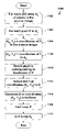
- a flowchart of a process 700 that may be used to generate a digital halftone (such as the digital halftones 630 and 640 ) corresponding to a source image on an output medium according to one embodiment of the present invention is shown.
- the process 700 generates dots corresponding to regions (e.g., individual pixels) in the source image. Dots are positioned within halftone pixels such that pairs of halftone dots contained within bordering halftone pixels extend in opposite directions from the halftone pixel boundaries of the halftone dots (as indicated by the vectors 654 a–i shown in FIG. 6F ). The size of each halftone dot generated by the method is proportional to the corresponding source image region.
- a variable DirectionStart is used to keep track of the direction in which the first dot in the current row is to extend.
- the value of DirectionStart may either be UP, indicating that the current dot is to extend upward from the bottom of a halftone pixel boundary, or DOWN, indicating that the current dot is to extend downward from the top of the halftone pixel boundary.
- the process 700 initially assigns a value of UP to the variable DirectionStart (step 702 ), indicating that the first dot in the halftone is to extend upward from the bottom of the first halftone pixel boundary.
- This initial value is chosen arbitrarily, and may alternatively be a value of DOWN. It should be appreciated that the values UP and DOWN may correspond to any opposing directions and do not specify a particular orientation.
- the process 700 enters into a loop over each row R in the source image (step 704 ).
- a variable D is used to keep track of the direction in which the current dot is to extend (either UP or DOWN).
- the variable D is assigned the current value of DirectionStart (step 706 ).
- the process 700 enters into an inner loop over each column C in the source image (step 708 ).
- the process 700 is now ready to process the source image pixel at coordinates (C, R), where C is the current column and R is the current row.
- a variable BND is used to store an identifier of the boundary (either BOTTOM or TOP) of the current halftone pixel from which the current spot is to extend. If the value of D is equal to UP (step 710 ), a value of BOTTOM is assigned to BND (step 712 ). Otherwise, a value of TOP is assigned to BND (step 714 ).
- the blackness of the source image pixel at coordinates (C, R) is stored in a variable B (step 716 ).
- the process 700 generates a dot: (1) in the halftone pixel H at coordinates (C, R), (2) having a size proportional to B, and (3) extending in direction D from boundary BND of halftone pixel H (step 718 ). For example, if the source image pixel at coordinates (0, 0) has a blackness of 128, then the process 700 generates a dot extending upward from the bottom of the halftone pixel at coordinates (0, 0) having a size that is proportional to 128.
- the process 700 toggles the value of Direction (step 720 ). More specifically, if the value of Direction is UP, then Direction is assigned a value of DOWN. Similarly, if the value of direction is DOWN, then Direction is assigned a value of UP. This ensures that horizontally-adjacent dots extend in different directions. Steps 710 – 720 are repeated for the remaining columns in row R (step 722 ).
- the process 700 toggles the value of DirectionStart (step 724 ). This ensures that vertically-adjacent dots extend in opposite directions from halftone pixel boundaries.
- Steps 706 – 724 are repeated for the remaining rows in the source image (step 726 ).
- FIGS. 7A–7B is shown merely for purposes of example and does not constitute a limitation of the present invention.
- the process 700 shown in FIGS. 7A–7B generates individual dots in both upward and downward directions.
- an output device such as a thermal printer, that renders dots only in a single direction and/or that renders multiple dots simultaneously.
- the process 700 shown in FIGS. 7A–7B generates adjoining dots in a dot pair separately, other processes that generate a single dot representing a dot pair are also within the scope of the present invention.
- the halftone generated by the process 700 may be rendered on an output medium either after the completion of the process 700 or as part of the process 700 . As described in more detail below with respect to FIG. 8B , the halftone generated by the process 700 may be either a logical halftone or a physical halftone.
- each dot in the halftone corresponds to a single source image pixel.
- This correspondence is used merely for purposes of example and does not constitute a limitation of the present invention. Rather, the source image 800 may be upsampled or downsampled by any factor prior to or during the halftoning process 802 .
- there may be any numerical correspondence between dots in the halftone 804 and pixels in the source image 800 so long as dots in dot pairs extend from common halftone pixel boundaries.
- each pixel in the source image 800 corresponds to multiple dots in the halftone 804 .
- each dot in the halftone 804 corresponds to multiple pixels in the source image 800 .
- glyphs are used to simulate a larger number of grayscale tones than can be simulated using individual dots.
- FIGS. 9A–9M a family of thirteen glyphs 900 a–m is shown that may be used to simulate thirteen shades of gray.
- Each of the glyphs 900 a–m consists of a 2 ⁇ 2 array of pixels, each of which may contain a halftone dot.
- glyph 900 a contains no dots.
- glyph 900 a contains four dots each of size zero.
- the size of a single dot is increased, where the coordinates of the dot whose size is increased are chosen in a round-robin fashion. For example, moving from glyph 900 a ( FIG. 9A ) to glyph 900 b ( FIG. 9B ), the size of the upper-left dot is increased (from no dot to a small dot). Similarly, moving to glyph 900 c ( FIG. 9C ), the size of the lower-right dot is increased (from no dot to a small dot). This pattern continues with the remaining glyphs, using four different dot sizes (counting a size of zero as a dot size). The result is the collection of thirteen glyphs 900 a–m , which can be used to simulate thirteen different shades of gray.
- glyphs 900 a–m are provided merely for purposes of illustration and do not constitute a limitation of the present invention. Furthermore, any family of glyphs may be used with various embodiments of the present invention.
- each region in the source image may be used to select one of the glyphs 900 a–m .
- this range of blackness is subdivided into thirteen sub-ranges, and each of the glyphs 900 a–m is assigned to one of the sub-ranges.
- the glyph corresponding to the source image pixel's blackness is generated at corresponding coordinates in the halftone.
- Various other schemes may be used to simulate tones using these glyphs.
- the source image may be downsampled, and the blackness of pixels in the downsampled source image may be used to select one of the glyphs 900 a–m for use in the halftone, as described above.
- this technique allows source images to be printed on output devices that do not have a sufficiently high spatial resolution to print one glyph for each source image pixel, high-frequency detail is lost by downsampling the source image.
- a method that avoids downsampling is used to produce a halftone from a source image using the glyphs 900 a–m .
- a source image 1000 is shown that consists of a 4 ⁇ 4 array of source image pixels.
- the source image 1000 is further logically subdivided into 2 ⁇ 2 arrays 1002 a–d of source image pixels, as indicated by thick lines in FIG. 10 .
- 2 ⁇ 2 arrays are chosen for purposes of example because in one embodiment of the present invention 2 ⁇ 2 glyphs are used to produce a halftone that simulates the source image 1000 .
- the source image 1000 may, however, be subdivided into pixel arrays of any size.
- arbitrarily-sized source image regions may be used instead of individual source image pixels.
- a process 1100 is used to produce a halftone that simulates the source image 1000 .
- the process 1100 enters into a loop over each 2 ⁇ 2 array A s of source image pixels (step 1102 ).
- the source image 1000 FIG. 10
- the process 1100 enters into an inner loop over each pixel P in the current array A s (step 1104 ).
- the variables X s and Y s are assigned the coordinates of the pixel P in the source image (step 1106 ). For example, the coordinates of the pixel in the upper-left corner of the source image 1000 are (0, 0), while the coordinates of the pixel in the lower-right corner of the source image 1000 are (3, 3).
- the variables X A and Y A are assigned the coordinates of the pixel P relative to the upper-left corner of the array AS (step 1108 ).
- the pixel in the lower-right corner of the source image 1000 has (X A , Y A ) coordinates (1, 1) relative to the upper-left corner of the array 1002 d
- the pixel in the lower-left corner of the source image 1000 has coordinates (0, 1) relative to the upper-left corner of the array 1002 c.
- the glyph G corresponding to the blackness of pixel P is selected (step 1110 ).
- the glyph G may be selected in any of a variety of ways.
- a family of glyphs (such as the family of glyphs 900 a–m ) may be pre-generated and stored in a lookup table.
- the blackness of pixel P may be used as an index in the lookup table to select the glyph G that corresponds to pixel P's blackness.
- the lookup table may, for example, represent each glyph as either: (1) a bitmap suitable for output on the output device 810 , or (2) a pattern of halftone dots that is rasterized (converted into a bitmap) at a later stage.
- the glyph G may be generated on the fly by step 1110 .
- step 1110 may use the dither matrix to generate the appropriate glyph G based on the blackness of pixel P.
- the dot (or dot pattern) D at coordinates (X A , Y A ) within glyph G is selected (step 1112 ). For example, if pixel P is in the lower-left hand corner of array A s , then coordinates (X A , Y A ) are (0, 1). In such a case, the dot at coordinates (0, 1) of the glyph G (i.e., the dot in its lower-left hand corner) would be selected as dot D in step 1112 .
- the dot D is generated (e.g., stored or rendered) at coordinates (X s , Y s ) in the halftone (step 1114 ). It should be appreciated that various techniques described above with respect to the process 700 ( FIGS. 7A–7B ) may be used to generate the dot D such that it extends in an appropriate direction from an appropriate halftone pixel boundary according to the halftone dot vectors 654 a–i ( FIG. 6F ). For example, in one embodiment of the present invention, dots are stored within pixels of the glyph G according to the halftone dot vectors of the array 650 ( FIG. 6F ). In other words, dots may be stored within the glyph G so that dots in adjacent pixels extend in opposite directions, as shown in FIG. 6F .
- dot D when dot D is generated at coordinates (X s , Y s ) in the halftone (step 1114 ) by copying dot D from the glyph G, the dot D is already positioned properly within the pixel P and therefore need not be shifted to be located in accordance with the array 650 ( FIG. 6F ).
- Steps 1106 – 1114 are repeated for the remaining pixels in the array A s (step 1116 ).
- Steps 1104 – 1118 are repeated for the remaining pixel arrays in the source image 1000 (step 1118 ).
- One advantage of using the process 1100 described above with respect to FIG. 11 is that it allows the simulation of a relatively large number of intensities, while still allowing individual source image pixels to specify the sizes of dots in the halftone. This enables a relatively large number of shades of gray to be simulated in the halftone, thereby producing more realistic halftones, while retaining high-frequency details compared to techniques that use the average intensity (or blackness) value of multiple source image pixels to generate dots or glyphs in the halftone.
- various embodiments of the present invention may be used to produce a halftone 804 from a source image 800 using a halftoning process 802 .
- the halftoning process 802 receives the source image 800 as an input, processes the source image 800 , and produces the halftone 804 as output.
- the source image 800 may, for example, be a continuous-tone image or a digital (discrete-tone) image acquired from any source.
- the source image 800 may undergo various preprocessing steps, such as color correction or color quantization, prior to being provided as an input to the halftoning process.
- the halftone 804 may be rendered on any output medium, such as plain paper or film.
- the halftone 804 may be digitally stored on any computer-readable medium such as a Random Access Memory (RAM), hard disk, floppy disk, or CD (such as a CD-ROM or CD-RW).
- RAM Random Access Memory
- CD such as a CD-ROM or CD-RW
- the term “generate” when applied to a halftone includes rendering the halftone on an output medium, storing the halftone on a computer-readable medium, or both.
- FIG. 8B one example of a system 810 in which various embodiments of the present invention may be used is shown.
- An image acquisition device 812 such as a scanner, captures a source image 814 and provides the source image 814 to a computer 816 using a digital transport mechanism, such as a standard serial or parallel cable.
- the image acquisition device 812 may be any image acquisition device, such as a scanner or digital camera.
- the computer 816 optionally stores the source image 814 in a computer-readable memory, such as a Random Access Memory (RAM) or a hard disk.
- the computer 816 may also perform additional processing on the source image 814 , such as reducing or enlarging the size of the source image 814 , applying filters to the source image 814 , or modifying the spatial or intensity resolution of the source image 814 .
- the computer 816 transmits the results as a logical halftone 818 to an output device 820 such as a thermal-transfer printer 820 using a digital transport mechanism.
- the term “logical halftone” refers to a halftone that is stored on a computer-readable medium.
- the output device 820 may be any output device, such as a thermal printer, laser printer, inkjet printer, or multi-function device.
- the output device 820 renders a physical halftone 822 based on the logical halftone 818 using any of the various techniques described herein on an output medium such as paper or film.
- the term “physical halftone” refers to a halftone that has been rendered on an output medium.
- system 810 shown in FIG. 8B is provided merely for purposes of example and does not constitute a limitation of the present invention. Rather, any appropriate system may be used to implement the techniques described herein.
- features of the image acquisition device 812 , the computer 816 , and the output device 820 may be combined into a lesser number of devices or separated into a greater number of devices for performing the functions described above.
- individual pixels in the source image 800 contribute to (i.e., control the size of) individual dots in the halftone.
- This correspondence between individual source image pixels and halftone dots enables the halftone 804 to retain high-frequency details from the source image 800 while simulating a large number of gray levels, thereby resulting in more faithful reproduction of the source image 800 .
- Another advantage of various embodiments of the present invention is that by combining dots together to form dot pairs, each such dot pair may be rendered in the halftone 804 using a single contiguous mark. This can reduce the number of dots that are output in the halftone, thereby increasing the perimeter-to-area ratio of the dots. Reduction of this parameter can result in higher-quality dots because dots produced by various output devices tend to exhibit poorer quality at the perimeter than within the perimeter.
- Various embodiments of the present invention also reduce the presence of certain visual artifacts that may be introduced by digital halftoning. For example, arranging dots at 45-degree angles (as shown in FIG. 6D ), or at a 38-degree angle, as shown in FIG. 6E , reduces the visual impact of the patterns because the human eye is better able to perceive such patterns when they result from dots arranged in a grid whose rows and columns are arranged horizontally and vertically in the field of vision.
- Various embodiments of the present invention have the further advantage that they reduce visual artifacts while still substantially retaining fine (high spatial frequency details) from the source image 800 , as described above.
- intensity typically refers to the amount of light reflected from within a particular region of an image.
- intensity also refers to a value that may be used to represent a tone for a region.
- an intensity may be a value representing a shade of gray in a grayscale image or a color in a color image.
- an intensity may be represented as a scalar value.
- an intensity may be represented as an 8-bit scalar value having a range of 0–255.
- An intensity may also be represented, for example, as a floating point value having a range of 0–1.
- a halftone dot “extends” from a halftone pixel boundary if an edge of the dot abuts the halftone pixel boundary.
- the halftone dot 614 b extends downward from the top boundary of the halftone pixel 612 b .
- extend does not specify that a halftone dot be rendered in any direction or in any particular manner. Rather, a halftone dot that extends from a halftone pixel boundary may be rendered on an output medium in any manner.
- the halftone dot 614 c extends upward from the bottom boundary of the halftone pixel 612 c
- the dot within halftone pixel 612 c may, but need not be, rendered downward toward the bottom boundary of the halftone pixel 612 c.
- dots that are “proportional” in size to the blackness of source image regions refer to dots that are “proportional” in size to the blackness of source image regions. It should be appreciated that such proportionality includes, but is not limited to, strict numerical proportionality. For example, in one embodiment of the present invention, there are n dot sizes D 1 –D n , and there are m levels of blackness B 1 –B m . For any two dots having dot sizes D A and D B , corresponding to blacknesses B A and B B , respectively, if D B >D A , then B B >B A . Various other mappings between levels of blackness and dot size are also within the scope of the present invention. Furthermore, as used herein, the term “dot size” includes, but is not limited to, measures of size such as area and length.
- the techniques described above may be implemented, for example, in hardware, software, firmware, or any combination thereof.
- the techniques described above may be implemented in one or more computer programs executing on a programmable computer and/or printer including a processor, a storage medium readable by the processor (including, for example, volatile and non-volatile memory and/or storage elements), at least one input device, and at least one output device.
- Program code may be applied to data entered using the input device to perform the functions described herein and to generate output information.
- the output information may be applied to one or more output devices.
- Printers suitable for use with various embodiments of the present invention typically include a print engine and a printer controller.
- the printer controller receives print data from a host computer and generates page information, such as a logical halftone to be printed based on the print data.
- the printer controller transmits the page information to the print engine to be printed.
- the print engine performs the physical printing of the image specified by the page information on the output medium.
- Each computer program within the scope of the claims below may be implemented in any programming language, such as assembly language, machine language, a high-level procedural programming language, or an object-oriented programming language.
- the programming language may be a compiled or interpreted programming language.
- Each computer program may be implemented in a computer program product tangibly embodied in a machine-readable storage device for execution by a computer processor. Method steps of the invention may be performed by a computer processor executing a program tangibly embodied on a computer-readable medium to perform functions of the invention by operating on input and generating output.
Abstract
Description
Claims (23)
Priority Applications (7)
| Application Number | Priority Date | Filing Date | Title |
|---|---|---|---|
| US09/817,932 US6999202B2 (en) | 2001-03-27 | 2001-03-27 | Method for generating a halftone of a source image |
| CA002442100A CA2442100C (en) | 2001-03-27 | 2002-03-21 | Digital halftoning |
| PCT/US2002/008954 WO2002078320A2 (en) | 2001-03-27 | 2002-03-21 | Digital halftoning |
| JP2002576414A JP2004530344A (en) | 2001-03-27 | 2002-03-21 | Digital halftoning |
| EP02719326A EP1374557A2 (en) | 2001-03-27 | 2002-03-21 | Digital halftoning |
| JP2007217505A JP4405535B2 (en) | 2001-03-27 | 2007-08-23 | Digital halftoning |
| US12/031,151 USRE43149E1 (en) | 2001-03-27 | 2008-02-14 | Method for generating a halftone of a source image |
Applications Claiming Priority (1)
| Application Number | Priority Date | Filing Date | Title |
|---|---|---|---|
| US09/817,932 US6999202B2 (en) | 2001-03-27 | 2001-03-27 | Method for generating a halftone of a source image |
Related Child Applications (1)
| Application Number | Title | Priority Date | Filing Date |
|---|---|---|---|
| US12/031,151 Reissue USRE43149E1 (en) | 2001-03-27 | 2008-02-14 | Method for generating a halftone of a source image |
Publications (2)
| Publication Number | Publication Date |
|---|---|
| US20020159094A1 US20020159094A1 (en) | 2002-10-31 |
| US6999202B2 true US6999202B2 (en) | 2006-02-14 |
Family
ID=25224235
Family Applications (2)
| Application Number | Title | Priority Date | Filing Date |
|---|---|---|---|
| US09/817,932 Ceased US6999202B2 (en) | 2001-03-27 | 2001-03-27 | Method for generating a halftone of a source image |
| US12/031,151 Expired - Lifetime USRE43149E1 (en) | 2001-03-27 | 2008-02-14 | Method for generating a halftone of a source image |
Family Applications After (1)
| Application Number | Title | Priority Date | Filing Date |
|---|---|---|---|
| US12/031,151 Expired - Lifetime USRE43149E1 (en) | 2001-03-27 | 2008-02-14 | Method for generating a halftone of a source image |
Country Status (5)
| Country | Link |
|---|---|
| US (2) | US6999202B2 (en) |
| EP (1) | EP1374557A2 (en) |
| JP (2) | JP2004530344A (en) |
| CA (1) | CA2442100C (en) |
| WO (1) | WO2002078320A2 (en) |
Cited By (9)
| Publication number | Priority date | Publication date | Assignee | Title |
|---|---|---|---|---|
| US20040042047A1 (en) * | 2002-08-28 | 2004-03-04 | Norihiro Kawatoko | Image printing apparatus and image printing method |
| US20050195443A1 (en) * | 2004-03-08 | 2005-09-08 | Fuji Photo Film Co., Ltd. | Method and apparatus for processing images |
| US20050219344A1 (en) * | 2002-02-19 | 2005-10-06 | Polaroid Corporation | Technique for printing a color image |
| US20090034008A1 (en) * | 2007-08-03 | 2009-02-05 | Lawrence Croft | Method for generating stochastic dither matrix |
| US20090128613A1 (en) * | 2001-05-30 | 2009-05-21 | Alain Bouchard | High Speed Photo-Printing Apparatus |
| US7826660B2 (en) | 2003-02-27 | 2010-11-02 | Saquib Suhail S | Digital image exposure correction |
| USRE42473E1 (en) | 2001-05-30 | 2011-06-21 | Senshin Capital, Llc | Rendering images utilizing adaptive error diffusion |
| USRE43149E1 (en) | 2001-03-27 | 2012-01-31 | Senshin Capital, Llc | Method for generating a halftone of a source image |
| US8773685B2 (en) | 2003-07-01 | 2014-07-08 | Intellectual Ventures I Llc | High-speed digital image printing system |
Families Citing this family (7)
| Publication number | Priority date | Publication date | Assignee | Title |
|---|---|---|---|---|
| WO2002096651A2 (en) * | 2001-05-30 | 2002-12-05 | Polaroid Corporation | A high speed photo-printing apparatus |
| US20040066538A1 (en) * | 2002-10-04 | 2004-04-08 | Rozzi William A. | Conversion of halftone bitmaps to continuous tone representations |
| US7616341B2 (en) * | 2004-07-12 | 2009-11-10 | Toshiba Corporation | System and method for metadata controlled multi-configured halftone screening |
| US7869094B2 (en) * | 2005-01-07 | 2011-01-11 | Mitcham Global Investments Ltd. | Selective dithering |
| CN101180637A (en) * | 2005-05-25 | 2008-05-14 | 爱克发印艺公司 | Image processing method and apparatus for improving the image quality of a dot matrix printer |
| JP5137558B2 (en) * | 2007-12-20 | 2013-02-06 | キヤノン株式会社 | Image processing apparatus and image processing method |
| WO2020242463A1 (en) * | 2019-05-29 | 2020-12-03 | Hewlett-Packard Development Company, L.P. | Color surface formation by single-color 3d printing |
Citations (9)
| Publication number | Priority date | Publication date | Assignee | Title |
|---|---|---|---|---|
| US5130821A (en) * | 1990-04-16 | 1992-07-14 | Eastman Kodak Company | Method and apparatus for digital halftoning employing density distribution for selection of a threshold template |
| US5323245A (en) | 1990-09-14 | 1994-06-21 | Minnesota Mining And Manufacturing Company | Perpendicular, unequal frequency non-conventional screen patterns for electronic halftone generation |
| US5479263A (en) | 1993-07-01 | 1995-12-26 | Xerox Corporation | Gray pixel halftone encoder |
| US5602653A (en) | 1994-11-08 | 1997-02-11 | Xerox Corporation | Pixel pair grid halftoning for a hyperacuity printer |
| US5777599A (en) | 1992-02-14 | 1998-07-07 | Oki Electric Industry Co., Ltd. | Image generation device and method using dithering |
| US5956421A (en) | 1996-02-28 | 1999-09-21 | Canon Kabushiki Kaisha | Image processing method and apparatus for determining a binarization threshold value used for binarizing a multi-valued image and performing binarization processing |
| US6104502A (en) | 1996-04-30 | 2000-08-15 | Dainippon Screen Mfg. Co., Ltd. | Method and apparatus for generating halftone dots for color printing |
| US6108105A (en) | 1988-09-08 | 2000-08-22 | Canon Kabushiki Kaisha | Dot image output apparatus |
| US6128099A (en) | 1995-06-08 | 2000-10-03 | Delabastita; Paul A. | Halftone screen generator, halftone screen and method for generating same |
Family Cites Families (206)
| Publication number | Priority date | Publication date | Assignee | Title |
|---|---|---|---|---|
| US3820133A (en) | 1972-07-24 | 1974-06-25 | C Adorney | Teaching device |
| US3864708A (en) | 1973-12-04 | 1975-02-04 | Brian S Allen | Automatic photographic apparatus and postcard vending machine |
| US4070587A (en) | 1975-02-14 | 1978-01-24 | Canon Kabushiki Kaisha | Energizing control system for an intermittently energized device |
| US4072973A (en) | 1976-01-26 | 1978-02-07 | Mayo William D | Camera signal system for portrait taking |
| US4089017A (en) | 1976-09-07 | 1978-05-09 | Polaroid Corporation | Automatic photostudio |
| JPH10285390A (en) | 1997-04-03 | 1998-10-23 | Minolta Co Ltd | Image processor |
| US4154523A (en) | 1977-05-31 | 1979-05-15 | Eastman Kodak Company | Exposure determination apparatus for a photographic printer |
| US4168120A (en) | 1978-04-17 | 1979-09-18 | Pako Corporation | Automatic exposure corrections for photographic printer |
| JPS5590383A (en) | 1978-12-27 | 1980-07-08 | Canon Inc | Thermal printer |
| US4284876A (en) | 1979-04-24 | 1981-08-18 | Oki Electric Industry Co., Ltd. | Thermal printing system |
| US4347518A (en) | 1979-09-04 | 1982-08-31 | Gould Inc. | Thermal array protection apparatus |
| JPS6036397B2 (en) | 1980-03-31 | 1985-08-20 | 株式会社東芝 | thermal recording device |
| JPS574784A (en) | 1980-06-13 | 1982-01-11 | Canon Inc | Thermal printer |
| US4385302A (en) | 1980-10-16 | 1983-05-24 | Fuji Xerox Co., Ltd. | Multicolor recording apparatus |
| JPS57138960A (en) | 1981-02-20 | 1982-08-27 | Fuji Xerox Co Ltd | Multicolor heat sensitive recorder |
| DE3273429D1 (en) | 1981-06-19 | 1986-10-30 | Toshiba Kk | Thermal printer |
| US4391535A (en) | 1981-08-10 | 1983-07-05 | Intermec Corporation | Method and apparatus for controlling the area of a thermal print medium that is exposed by a thermal printer |
| JPS58150370A (en) | 1982-03-02 | 1983-09-07 | Sony Corp | Producing system of gradation signal for printer |
| JPS58164368U (en) | 1982-04-26 | 1983-11-01 | 日立電子株式会社 | Television camera characteristic automatic adjustment device |
| US4514738A (en) | 1982-11-22 | 1985-04-30 | Tokyo Shibaura Denki Kabushiki Kaisha | Thermal recording system |
| JPS59127781A (en) | 1983-01-11 | 1984-07-23 | Fuji Xerox Co Ltd | Driving circuit for thermal head |
| JPS59127781U (en) | 1983-02-16 | 1984-08-28 | 株式会社トーキン | Vibration feedback ultrasonic oscillator |
| JPS59182758A (en) | 1983-04-01 | 1984-10-17 | Fuji Xerox Co Ltd | Drive circuit for thermal head |
| US4540992A (en) | 1983-04-07 | 1985-09-10 | Kabushiki Kaisha Daini Seikosha | Thermal color transfer system |
| US4688051A (en) | 1983-08-15 | 1987-08-18 | Ricoh Company, Ltd. | Thermal print head driving system |
| JPS6085675A (en) | 1983-10-17 | 1985-05-15 | Fuji Xerox Co Ltd | Color copying machine |
| JPS60101051A (en) | 1983-11-09 | 1985-06-05 | Fuji Xerox Co Ltd | Multicolor recording system |
| US4563691A (en) | 1984-12-24 | 1986-01-07 | Fuji Xerox Co., Ltd. | Thermo-sensitive recording apparatus |
| US4884080A (en) | 1985-01-31 | 1989-11-28 | Kabushiki Kaisha Toshiba | Color image printing apparatus |
| JPH0324972Y2 (en) | 1985-02-13 | 1991-05-30 | ||
| DE3688715T3 (en) * | 1985-03-30 | 1999-05-06 | Hitachi Ltd | Scanning record type printing method and its realization device. |
| JPH0140371Y2 (en) | 1985-08-29 | 1989-12-04 | ||
| US4686549A (en) | 1985-12-16 | 1987-08-11 | Minnesota Mining And Manufacturing Company | Receptor sheet for thermal mass transfer printing |
| JPS62275768A (en) | 1986-05-24 | 1987-11-30 | Sony Corp | Printer |
| US4738526A (en) | 1986-11-21 | 1988-04-19 | Autostudio Corporation | Auto-portrait photo studio |
| JPS63202182A (en) | 1987-02-18 | 1988-08-22 | Olympus Optical Co Ltd | Tilted dot pattern forming method |
| US4739344A (en) | 1987-02-27 | 1988-04-19 | Astro-Med, Inc. | Chart recorded having multiple thermal print heads |
| JPH02139258A (en) | 1988-08-18 | 1990-05-29 | Ricoh Co Ltd | Apparatus for correcting recording density |
| US5086484A (en) | 1988-08-24 | 1992-02-04 | Canon Kabushiki Kaisha | Image processing apparatus with fixed or variable threshold |
| JPH02121853A (en) | 1988-10-31 | 1990-05-09 | Toshiba Corp | Thermal head control circuit |
| JP2984009B2 (en) | 1989-02-03 | 1999-11-29 | 株式会社リコー | Thermal head drive |
| JPH0813552B2 (en) | 1989-02-17 | 1996-02-14 | 松下電器産業株式会社 | Gradation printer |
| JPH02289368A (en) | 1989-03-08 | 1990-11-29 | Hitachi Ltd | Printing method |
| JPH02235655A (en) | 1989-03-09 | 1990-09-18 | Kyocera Corp | Driving device of thermal head |
| JPH02248264A (en) | 1989-03-20 | 1990-10-04 | Fujitsu Ltd | Thermal recorder having temperature predictive constant controlling performance |
| US5086306A (en) | 1989-07-19 | 1992-02-04 | Ricoh Company, Ltd. | Line head driving apparatus |
| JP2523188B2 (en) | 1989-08-07 | 1996-08-07 | シャープ株式会社 | Printing control method of thermal printer |
| US5045952A (en) | 1989-08-21 | 1991-09-03 | Xerox Corporation | Method for edge enhanced error diffusion |
| JP2612616B2 (en) | 1989-08-31 | 1997-05-21 | 富士写真フイルム株式会社 | Method and apparatus for driving thermal head in printer |
| US4933709A (en) | 1989-09-25 | 1990-06-12 | Eastman Kodak Company | Adjusting photographic printer color exposure determination algorithms |
| US5285220A (en) | 1989-11-22 | 1994-02-08 | Canon Kabushiki Kaisha | Image recording apparatus with tone correction for individual recording heads |
| US4962403A (en) | 1989-12-11 | 1990-10-09 | Eastman Kodak Company | Adjusting photographic printer color exposure determination algorithms |
| US5046118A (en) | 1990-02-06 | 1991-09-03 | Eastman Kodak Company | Tone-scale generation method and apparatus for digital x-ray images |
| JP3168580B2 (en) | 1990-04-05 | 2001-05-21 | セイコーエプソン株式会社 | Page description language interpreter |
| US5208684A (en) | 1990-04-26 | 1993-05-04 | Fujitsu Limited | Half-tone image processing system |
| JP2969872B2 (en) | 1990-09-10 | 1999-11-02 | 株式会社ニコン | Photometric calculation device for camera |
| US5268706A (en) | 1991-02-14 | 1993-12-07 | Alps Electric Co., Ltd. | Actuating control method of thermal head |
| JP2957721B2 (en) | 1991-02-25 | 1999-10-06 | アルプス電気株式会社 | Thermal control method of thermal head |
| US5132703A (en) | 1991-03-08 | 1992-07-21 | Yokogawa Electric Corporation | Thermal history control in a recorder using a line thermal head |
| US5132709A (en) | 1991-08-26 | 1992-07-21 | Zebra Technologies Corporation | Apparatus and method for closed-loop, thermal control of printing head |
| US5307425A (en) | 1991-09-02 | 1994-04-26 | Rohm Co., Ltd. | Bi-level halftone processing circuit and image processing apparatus using the same |
| US5244861A (en) | 1992-01-17 | 1993-09-14 | Eastman Kodak Company | Receiving element for use in thermal dye transfer |
| US5625399A (en) | 1992-01-31 | 1997-04-29 | Intermec Corporation | Method and apparatus for controlling a thermal printhead |
| JPH0654195A (en) | 1992-02-28 | 1994-02-25 | Eastman Kodak Co | System and method for image scanner for improvement of microfilm image quality |
| JPH07205469A (en) | 1992-03-27 | 1995-08-08 | Nec Data Terminal Ltd | Thermal head |
| JP3412174B2 (en) | 1992-05-21 | 2003-06-03 | 松下電器産業株式会社 | Automatic exposure control device |
| JP3209797B2 (en) | 1992-07-03 | 2001-09-17 | 松下電器産業株式会社 | Gradation printer |
| US5469533A (en) | 1992-07-10 | 1995-11-21 | Microsoft Corporation | Resource-oriented printer system and method of operation |
| JP2850930B2 (en) | 1992-10-12 | 1999-01-27 | 日本ビクター株式会社 | Melt type thermal transfer printing system |
| US5729274A (en) | 1992-11-05 | 1998-03-17 | Fuji Photo Film Co., Ltd. | Color direct thermal printing method and thermal head of thermal printer |
| US5469203A (en) | 1992-11-24 | 1995-11-21 | Eastman Kodak Company | Parasitic resistance compensation for a thermal print head |
| US5644351A (en) | 1992-12-04 | 1997-07-01 | Matsushita Electric Industrial Co., Ltd. | Thermal gradation printing apparatus |
| JPH06183033A (en) | 1992-12-18 | 1994-07-05 | Canon Inc | Ink jet recorder |
| US5450099A (en) | 1993-04-08 | 1995-09-12 | Eastman Kodak Company | Thermal line printer with staggered head segments and overlap compensation |
| JP3365818B2 (en) | 1993-04-26 | 2003-01-14 | 富士写真フイルム株式会社 | Print density control method |
| KR0138362B1 (en) | 1993-05-17 | 1998-05-15 | 김광호 | Thermal transfer printing apparatus and method |
| US5805780A (en) | 1993-05-25 | 1998-09-08 | Dai Nippon Printing Co., Ltd. | Photographing box |
| JP3397371B2 (en) | 1993-05-27 | 2003-04-14 | キヤノン株式会社 | Recording device and recording method |
| US5818474A (en) | 1993-06-30 | 1998-10-06 | Canon Kabushiki Kaisha | Ink-jet recording apparatus and method using asynchronous masks |
| US5623297A (en) | 1993-07-07 | 1997-04-22 | Intermec Corporation | Method and apparatus for controlling a thermal printhead |
| DE4335143A1 (en) | 1993-10-15 | 1995-04-20 | Hell Ag Linotype | Method and device for converting color values |
| US5956067A (en) | 1993-10-28 | 1999-09-21 | Nisca Corporation | Thermal transfer printing device and method |
| US6133983A (en) | 1993-11-12 | 2000-10-17 | Eastman Kodak Company | Photographic printing method and apparatus for setting a degree of illuminant chromatic correction using inferential illuminant detection |
| JP2746088B2 (en) | 1993-11-30 | 1998-04-28 | 進工業株式会社 | Thermal head device |
| JP3066237B2 (en) | 1993-12-21 | 2000-07-17 | フジコピアン株式会社 | Thermal transfer material and color image forming method |
| JPH07178948A (en) | 1993-12-24 | 1995-07-18 | Shinko Electric Co Ltd | Thermal printer |
| DE69425124T2 (en) | 1993-12-27 | 2001-03-22 | Sharp Kk | Process for gradation control and image quality improvement in a thermal printer |
| US5497174A (en) | 1994-03-11 | 1996-03-05 | Xerox Corporation | Voltage drop correction for ink jet printer |
| US5786900A (en) | 1994-03-23 | 1998-07-28 | Fuji Photo Film Co., Ltd. | Image recording device for recording multicolor images with dot pitch pattern randomly arranged only in the sub-scanning direction |
| JP3381755B2 (en) | 1994-10-11 | 2003-03-04 | セイコーエプソン株式会社 | Method and apparatus for improved adaptive filtering and thresholding to reduce image graininess |
| US5786837A (en) | 1994-11-29 | 1998-07-28 | Agfa-Gevaert N.V. | Method and apparatus for thermal printing with voltage-drop compensation |
| JP2702426B2 (en) | 1994-12-16 | 1998-01-21 | 日本電気データ機器株式会社 | Thermal head device |
| JPH08169132A (en) | 1994-12-20 | 1996-07-02 | Nec Data Terminal Ltd | Thermal head device |
| US5724456A (en) | 1995-03-31 | 1998-03-03 | Polaroid Corporation | Brightness adjustment of images using digital scene analysis |
| US5694484A (en) | 1995-05-15 | 1997-12-02 | Polaroid Corporation | System and method for automatically processing image data to provide images of optimal perceptual quality |
| US5835627A (en) | 1995-05-15 | 1998-11-10 | Higgins; Eric W. | System and method for automatically optimizing image quality and processing time |
| US5707082A (en) | 1995-07-18 | 1998-01-13 | Moore Business Forms Inc | Thermally imaged colored baggage tags |
| US6657741B1 (en) | 1995-08-07 | 2003-12-02 | Tr Systems, Inc. | Multiple print engine system with selectively distributed ripped pages |
| JPH0952382A (en) | 1995-08-17 | 1997-02-25 | Fuji Photo Film Co Ltd | Method and apparatus for correcting heat accumulation |
| US5812286A (en) | 1995-08-30 | 1998-09-22 | Hewlett-Packard Company | Automatic color processing to correct hue shift and incorrect exposure |
| US5664253A (en) | 1995-09-12 | 1997-09-02 | Eastman Kodak Company | Stand alone photofinishing apparatus |
| JP3501567B2 (en) | 1995-09-28 | 2004-03-02 | 富士写真フイルム株式会社 | Color thermal printer |
| JP3523724B2 (en) | 1995-09-29 | 2004-04-26 | 東芝テック株式会社 | Thermal transfer color printer |
| KR100378492B1 (en) | 1995-10-27 | 2004-05-20 | 삼성테크윈 주식회사 | Photographic printing device |
| JP3783792B2 (en) | 1995-11-09 | 2006-06-07 | 富士写真フイルム株式会社 | Image processing method in photographic printer |
| JPH09167129A (en) | 1995-12-19 | 1997-06-24 | Fuji Xerox Co Ltd | Network system |
| US5623581A (en) | 1996-01-22 | 1997-04-22 | Apbi Interactive Kiosk Systems | Direct view interactive photo kiosk and image forming process for same |
| US5913019A (en) | 1996-01-22 | 1999-06-15 | Foto Fantasy, Inc. | Direct view interactive photo kiosk and composite image forming process for same |
| JP3625333B2 (en) | 1996-02-13 | 2005-03-02 | 富士写真フイルム株式会社 | Thermal image recording apparatus and recording method |
| US5777638A (en) | 1996-02-22 | 1998-07-07 | Hewlett-Packard Company | Print mode to compensate for microbanding |
| JPH09247473A (en) | 1996-03-07 | 1997-09-19 | Minolta Co Ltd | Image forming device |
| US5809164A (en) | 1996-03-07 | 1998-09-15 | Polaroid Corporation | System and method for color gamut and tone compression using an ideal mapping function |
| JP3589783B2 (en) | 1996-04-11 | 2004-11-17 | 富士写真フイルム株式会社 | Thermal storage correction method and device |
| US5880777A (en) | 1996-04-15 | 1999-03-09 | Massachusetts Institute Of Technology | Low-light-level imaging and image processing |
| US5889546A (en) | 1996-06-04 | 1999-03-30 | Shinko Electric Co., Ltd. | Heat accumulation control device for line-type thermoelectric printer |
| US5809177A (en) | 1996-06-06 | 1998-09-15 | Xerox Corporation | Hybrid error diffusion pattern shifting reduction using programmable threshold perturbation |
| JPH1013682A (en) | 1996-06-21 | 1998-01-16 | Nikon Corp | Image processing method |
| US5668638A (en) | 1996-06-27 | 1997-09-16 | Xerox Corporation | Error diffusion method with symmetric enhancement |
| JPH1076693A (en) | 1996-07-12 | 1998-03-24 | Victor Co Of Japan Ltd | Melt type thermal transfer printer and printing paper therefor |
| US6128415A (en) | 1996-09-06 | 2000-10-03 | Polaroid Corporation | Device profiles for use in a digital image processing system |
| US6233360B1 (en) | 1996-09-24 | 2001-05-15 | Xerox Corporation | Method and system for hybrid error diffusion processing of image information using adaptive white and black reference values |
| JPH10109436A (en) | 1996-10-04 | 1998-04-28 | Seiko Denshi Kiki Kk | Color image recording method, color image recording device, and color image recording controlling method |
| US5818975A (en) | 1996-10-28 | 1998-10-06 | Eastman Kodak Company | Method and apparatus for area selective exposure adjustment |
| JPH10239780A (en) | 1996-12-24 | 1998-09-11 | Fuji Photo Film Co Ltd | Method and device for outputting photographic image data |
| US6243133B1 (en) | 1997-03-07 | 2001-06-05 | Eastman Kodak Company | Method for automatic scene balance of digital images |
| US6249315B1 (en) | 1997-03-24 | 2001-06-19 | Jack M. Holm | Strategy for pictorial digital image processing |
| US5970224A (en) | 1997-04-14 | 1999-10-19 | Xerox Corporation | Multifunctional printing system with queue management |
| JPH1110852A (en) | 1997-06-24 | 1999-01-19 | Fuji Photo Film Co Ltd | Multihead type printer |
| JP3683387B2 (en) | 1997-08-01 | 2005-08-17 | シャープ株式会社 | Network computer built-in printer and computer network system provided with the same |
| JPH1158807A (en) | 1997-08-11 | 1999-03-02 | Minolta Co Ltd | Recorder |
| US6263091B1 (en) | 1997-08-22 | 2001-07-17 | International Business Machines Corporation | System and method for identifying foreground and background portions of digitized images |
| JP3690082B2 (en) | 1997-09-11 | 2005-08-31 | コニカミノルタビジネステクノロジーズ株式会社 | Selection method of image forming apparatus connected to network |
| US6334660B1 (en) | 1998-10-31 | 2002-01-01 | Hewlett-Packard Company | Varying the operating energy applied to an inkjet print cartridge based upon the operating conditions |
| US6069982A (en) | 1997-12-23 | 2000-05-30 | Polaroid Corporation | Estimation of frequency dependence and grey-level dependence of noise in an image |
| US6101000A (en) | 1998-01-30 | 2000-08-08 | Eastman Kodak Company | Photographic processing apparatus and method |
| US6172768B1 (en) | 1998-02-05 | 2001-01-09 | Canon Kabushiki Kaisha | Halftoning with changeable error diffusion weights |
| US6223267B1 (en) | 1998-02-26 | 2001-04-24 | Hewlett-Packard Company | Dynamically allocable RAM disk |
| US6106173A (en) | 1998-03-06 | 2000-08-22 | Asahi Kogaku Kogyo Kabushiki Kaisha | Image-forming system including a plurality of thermal heads and an image-forming sheet with a plurality of types of micro-capsules |
| US6226021B1 (en) | 1998-04-03 | 2001-05-01 | Alps Electric Co., Ltd. | Image forming method of thermal transfer printer |
| US6760489B1 (en) | 1998-04-06 | 2004-07-06 | Seiko Epson Corporation | Apparatus and method for image data interpolation and medium on which image data interpolation program is recorded |
| WO1999053415A1 (en) | 1998-04-15 | 1999-10-21 | Hewlett-Packard Company | Distributed processing over a network |
| US6204940B1 (en) | 1998-05-15 | 2001-03-20 | Hewlett-Packard Company | Digital processing of scanned negative films |
| US5995654A (en) | 1998-05-28 | 1999-11-30 | Eastman Kodak Company | Digital photofinishing system including scene balance and image sharpening digital image processing |
| US6233069B1 (en) | 1998-05-28 | 2001-05-15 | Eastman Kodak Company | Digital photofinishing system including film under exposure gamma, scene balance, contrast normalization, and image sharpening digital image processing |
| EP0961482B1 (en) | 1998-05-28 | 2007-12-12 | Eastman Kodak Company | Digital photofinishing system including digital image processing of alternative capture color photographic media |
| US6631208B1 (en) | 1998-05-29 | 2003-10-07 | Fuji Photo Film Co., Ltd. | Image processing method |
| US6208429B1 (en) | 1998-05-29 | 2001-03-27 | Flashpoint Technology, Inc. | Method and system for band printing of rotated digital image data |
| JP3590265B2 (en) | 1998-06-11 | 2004-11-17 | 富士写真フイルム株式会社 | Image processing method |
| US6694051B1 (en) | 1998-06-24 | 2004-02-17 | Canon Kabushiki Kaisha | Image processing method, image processing apparatus and recording medium |
| JP3492202B2 (en) | 1998-06-24 | 2004-02-03 | キヤノン株式会社 | Image processing method, apparatus and recording medium |
| US6104468A (en) | 1998-06-29 | 2000-08-15 | Eastman Kodak Company | Image movement in a photographic laboratory |
| US6462835B1 (en) | 1998-07-15 | 2002-10-08 | Kodak Polychrome Graphics, Llc | Imaging system and method |
| JP3556859B2 (en) | 1998-09-08 | 2004-08-25 | 富士写真フイルム株式会社 | Image correction method, image correction device, and recording medium |
| JP3754849B2 (en) | 1998-10-30 | 2006-03-15 | キヤノン株式会社 | Data communication apparatus, control method, storage medium, and image printing system |
| JP3829508B2 (en) | 1998-11-27 | 2006-10-04 | セイコーエプソン株式会社 | Image processing apparatus, image processing method, and printing apparatus |
| JP2000184270A (en) | 1998-12-14 | 2000-06-30 | Ricoh Co Ltd | Digital still video camera |
| US6282317B1 (en) | 1998-12-31 | 2001-08-28 | Eastman Kodak Company | Method for automatic determination of main subjects in photographic images |
| JP3820497B2 (en) | 1999-01-25 | 2006-09-13 | 富士写真フイルム株式会社 | Imaging apparatus and correction processing method for automatic exposure control |
| JP3369497B2 (en) | 1999-01-27 | 2003-01-20 | 松下電送システム株式会社 | Terminal device and MFP |
| US6276775B1 (en) | 1999-04-29 | 2001-08-21 | Hewlett-Packard Company | Variable drop mass inkjet drop generator |
| US6781713B1 (en) | 1999-05-20 | 2004-08-24 | Eastman Kodak Company | Correcting exposure in a rendered digital image |
| TW473696B (en) | 1999-06-29 | 2002-01-21 | Casio Computer Co Ltd | Printing apparatus and printing method |
| JP2002096470A (en) | 1999-08-24 | 2002-04-02 | Canon Inc | Device for recording, nethod for controlling the same, and computer readable memory |
| ATE310644T1 (en) | 1999-09-29 | 2005-12-15 | Seiko Epson Corp | PRINTING DEVICE, METHOD FOR CONTROLLING SAME AND A DATA STORAGE MEDIUM FOR STORING A COMPUTER PROGRAM EXECUTING THE METHOD |
| US6425699B1 (en) | 1999-09-29 | 2002-07-30 | Hewlett-Packard Company | Use of very small advances of printing medium for improved image quality in incremental printing |
| US6690488B1 (en) | 1999-09-30 | 2004-02-10 | Polaroid Corporation | Method and apparatus for estimating the spatial frequency response of a digital image acquisition system from the images it produces |
| US6628899B1 (en) | 1999-10-08 | 2003-09-30 | Fuji Photo Film Co., Ltd. | Image photographing system, image processing system, and image providing system connecting them, as well as photographing camera, image editing apparatus, image order sheet for each object and method of ordering images for each object |
| KR100601312B1 (en) | 1999-10-19 | 2006-07-13 | 삼성테크윈 주식회사 | Apparatus for correlating of exposure automatically of a digital still camera and method for performing the same |
| EP1222526A1 (en) | 1999-10-19 | 2002-07-17 | Electronics for Imaging, Inc. | Automatic print load balancing |
| US6856416B1 (en) | 1999-11-03 | 2005-02-15 | Toshiba Tech Corporation | Dynamic load balancing for a tandem printing system |
| GB2356375B (en) | 1999-11-22 | 2003-04-09 | Esselte Nv | A method of controlling a print head |
| US6650771B1 (en) | 1999-11-22 | 2003-11-18 | Eastman Kodak Company | Color management system incorporating parameter control channels |
| US6628826B1 (en) | 1999-11-29 | 2003-09-30 | Eastman Kodak Company | Color reproduction of images from color films |
| JP4172122B2 (en) | 1999-12-02 | 2008-10-29 | ノーリツ鋼機株式会社 | Color density correction method, recording medium having recorded color density correction program, image processing apparatus, and photographic printing apparatus |
| JP2001186323A (en) | 1999-12-24 | 2001-07-06 | Fuji Photo Film Co Ltd | Identification photograph system and picture on processing method |
| EP1137247A3 (en) | 2000-01-28 | 2002-10-09 | Eastman Kodak Company | Photofinishing system and method |
| US6537410B2 (en) | 2000-02-01 | 2003-03-25 | Polaroid Corporation | Thermal transfer recording system |
| US7092116B2 (en) | 2000-06-29 | 2006-08-15 | Douglas Calaway | Method and system for processing an annotated digital photograph using a composite image |
| US6762855B1 (en) | 2000-07-07 | 2004-07-13 | Eastman Kodak Company | Variable speed printing system |
| US6583852B2 (en) | 2000-09-21 | 2003-06-24 | Shutterfly, Inc. | Apparatus, architecture and method for high-speed printing |
| JP3740403B2 (en) | 2000-10-23 | 2006-02-01 | キヤノン株式会社 | Printing system, printing control apparatus, information processing method, control program |
| EP1201449A3 (en) | 2000-10-31 | 2003-05-14 | Hewlett-Packard Company | A system and method for improving the edge quality of inkjet printouts |
| JP2002160395A (en) | 2000-11-22 | 2002-06-04 | Fuji Photo Film Co Ltd | Method and device for recording image |
| US7272390B1 (en) | 2000-12-19 | 2007-09-18 | Cisco Technology, Inc. | Method and system for sending facsimile transmissions from mobile devices |
| US7355732B2 (en) | 2000-12-22 | 2008-04-08 | Ricoh Company, Ltd. | Printing mechanism for wireless devices |
| WO2002054234A1 (en) | 2001-01-08 | 2002-07-11 | Hyperdrive Computers Limited | Computer system with operating system on a ram-disk |
| JP4662401B2 (en) | 2001-02-05 | 2011-03-30 | ローム株式会社 | Printing method and thermal printer |
| US7154621B2 (en) | 2001-03-20 | 2006-12-26 | Lightsurf Technologies, Inc. | Internet delivery of digitized photographs |
| US6999202B2 (en) | 2001-03-27 | 2006-02-14 | Polaroid Corporation | Method for generating a halftone of a source image |
| US6842186B2 (en) | 2001-05-30 | 2005-01-11 | Polaroid Corporation | High speed photo-printing apparatus |
| WO2002096651A2 (en) | 2001-05-30 | 2002-12-05 | Polaroid Corporation | A high speed photo-printing apparatus |
| US6937365B2 (en) | 2001-05-30 | 2005-08-30 | Polaroid Corporation | Rendering images utilizing adaptive error diffusion |
| JP4218229B2 (en) | 2001-06-27 | 2009-02-04 | カシオ計算機株式会社 | Imaging apparatus and exposure control method |
| US6826310B2 (en) | 2001-07-06 | 2004-11-30 | Jasc Software, Inc. | Automatic contrast enhancement |
| WO2003010955A1 (en) | 2001-07-23 | 2003-02-06 | Seiko Epson Corporation | Printing system and printing method |
| JP2003036438A (en) | 2001-07-25 | 2003-02-07 | Minolta Co Ltd | Program for specifying red-eye in image, recording medium, image processor and method for specifying red- eye |
| US6819347B2 (en) | 2001-08-22 | 2004-11-16 | Polaroid Corporation | Thermal response correction system |
| WO2003039143A1 (en) | 2001-10-30 | 2003-05-08 | Nikon Corporation | Image accumulation apparatus, image accumulation support apparatus, image accumulation system, image control apparatus, image storage apparatus |
| JP3992177B2 (en) | 2001-11-29 | 2007-10-17 | 株式会社リコー | Image processing apparatus, image processing method, and computer program |
| US6906736B2 (en) | 2002-02-19 | 2005-06-14 | Polaroid Corporation | Technique for printing a color image |
| EP1478514B1 (en) | 2002-02-22 | 2012-02-29 | Mitcham Global Investments Ltd. | Common mode voltage correction |
| JP3928704B2 (en) | 2002-02-26 | 2007-06-13 | セイコーエプソン株式会社 | Image processing apparatus, image processing method, medium storing image processing program, and image processing program |
| US6956967B2 (en) | 2002-05-20 | 2005-10-18 | Eastman Kodak Company | Color transformation for processing digital images |
| US7283666B2 (en) | 2003-02-27 | 2007-10-16 | Saquib Suhail S | Digital image exposure correction |
| US20040179226A1 (en) | 2003-03-10 | 2004-09-16 | Burkes Theresa A. | Accelerating printing |
| US8773685B2 (en) | 2003-07-01 | 2014-07-08 | Intellectual Ventures I Llc | High-speed digital image printing system |
-
2001
- 2001-03-27 US US09/817,932 patent/US6999202B2/en not_active Ceased
-
2002
- 2002-03-21 WO PCT/US2002/008954 patent/WO2002078320A2/en active Application Filing
- 2002-03-21 EP EP02719326A patent/EP1374557A2/en not_active Ceased
- 2002-03-21 CA CA002442100A patent/CA2442100C/en not_active Expired - Fee Related
- 2002-03-21 JP JP2002576414A patent/JP2004530344A/en not_active Withdrawn
-
2007
- 2007-08-23 JP JP2007217505A patent/JP4405535B2/en not_active Expired - Fee Related
-
2008
- 2008-02-14 US US12/031,151 patent/USRE43149E1/en not_active Expired - Lifetime
Patent Citations (9)
| Publication number | Priority date | Publication date | Assignee | Title |
|---|---|---|---|---|
| US6108105A (en) | 1988-09-08 | 2000-08-22 | Canon Kabushiki Kaisha | Dot image output apparatus |
| US5130821A (en) * | 1990-04-16 | 1992-07-14 | Eastman Kodak Company | Method and apparatus for digital halftoning employing density distribution for selection of a threshold template |
| US5323245A (en) | 1990-09-14 | 1994-06-21 | Minnesota Mining And Manufacturing Company | Perpendicular, unequal frequency non-conventional screen patterns for electronic halftone generation |
| US5777599A (en) | 1992-02-14 | 1998-07-07 | Oki Electric Industry Co., Ltd. | Image generation device and method using dithering |
| US5479263A (en) | 1993-07-01 | 1995-12-26 | Xerox Corporation | Gray pixel halftone encoder |
| US5602653A (en) | 1994-11-08 | 1997-02-11 | Xerox Corporation | Pixel pair grid halftoning for a hyperacuity printer |
| US6128099A (en) | 1995-06-08 | 2000-10-03 | Delabastita; Paul A. | Halftone screen generator, halftone screen and method for generating same |
| US5956421A (en) | 1996-02-28 | 1999-09-21 | Canon Kabushiki Kaisha | Image processing method and apparatus for determining a binarization threshold value used for binarizing a multi-valued image and performing binarization processing |
| US6104502A (en) | 1996-04-30 | 2000-08-15 | Dainippon Screen Mfg. Co., Ltd. | Method and apparatus for generating halftone dots for color printing |
Non-Patent Citations (1)
| Title |
|---|
| Digital Halftoning, Robert Ulichney, Cambridge, MA, The MIT Press (1987), ISBN, 0-262-21009-6, Chapter 5 and 6. |
Cited By (13)
| Publication number | Priority date | Publication date | Assignee | Title |
|---|---|---|---|---|
| USRE43149E1 (en) | 2001-03-27 | 2012-01-31 | Senshin Capital, Llc | Method for generating a halftone of a source image |
| USRE42473E1 (en) | 2001-05-30 | 2011-06-21 | Senshin Capital, Llc | Rendering images utilizing adaptive error diffusion |
| US20090128613A1 (en) * | 2001-05-30 | 2009-05-21 | Alain Bouchard | High Speed Photo-Printing Apparatus |
| US20110122213A1 (en) * | 2002-02-19 | 2011-05-26 | Alain Bouchard | Technique for printing a color image |
| US20050219344A1 (en) * | 2002-02-19 | 2005-10-06 | Polaroid Corporation | Technique for printing a color image |
| US7907157B2 (en) | 2002-02-19 | 2011-03-15 | Senshin Capital, Llc | Technique for printing a color image |
| US7548347B2 (en) * | 2002-08-28 | 2009-06-16 | Canon Kabushiki Kaisha | Image printing apparatus and image printing method |
| US20040042047A1 (en) * | 2002-08-28 | 2004-03-04 | Norihiro Kawatoko | Image printing apparatus and image printing method |
| US7826660B2 (en) | 2003-02-27 | 2010-11-02 | Saquib Suhail S | Digital image exposure correction |
| US8265420B2 (en) | 2003-02-27 | 2012-09-11 | Senshin Capital, Llc | Digital image exposure correction |
| US8773685B2 (en) | 2003-07-01 | 2014-07-08 | Intellectual Ventures I Llc | High-speed digital image printing system |
| US20050195443A1 (en) * | 2004-03-08 | 2005-09-08 | Fuji Photo Film Co., Ltd. | Method and apparatus for processing images |
| US20090034008A1 (en) * | 2007-08-03 | 2009-02-05 | Lawrence Croft | Method for generating stochastic dither matrix |
Also Published As
| Publication number | Publication date |
|---|---|
| WO2002078320A3 (en) | 2003-03-20 |
| CA2442100C (en) | 2007-06-19 |
| JP2004530344A (en) | 2004-09-30 |
| JP2007329967A (en) | 2007-12-20 |
| US20020159094A1 (en) | 2002-10-31 |
| CA2442100A1 (en) | 2002-10-03 |
| JP4405535B2 (en) | 2010-01-27 |
| WO2002078320A2 (en) | 2002-10-03 |
| USRE43149E1 (en) | 2012-01-31 |
| EP1374557A2 (en) | 2004-01-02 |
Similar Documents
| Publication | Publication Date | Title |
|---|---|---|
| USRE43149E1 (en) | Method for generating a halftone of a source image | |
| US5602572A (en) | Thinned halftone dot patterns for inkjet printing | |
| US7513589B2 (en) | Multipass printing | |
| US5642439A (en) | Digital image processing method suitable for halftone representation based on dither process | |
| US5463471A (en) | Method and system of color halftone reproduction | |
| JP3985437B2 (en) | Electrophotographic image forming apparatus and image forming program product thereof | |
| EP1107178A2 (en) | Gradient-based trapping using patterned trap zones | |
| JPH0757104A (en) | Screen processing method of rendering device having limited density resolution | |
| US5689586A (en) | Methods to print N-tone images with multi-leveling techniques | |
| US5615021A (en) | Print N-tone images with imperceptible dots | |
| US5777757A (en) | Method and system for halftoning | |
| JP3109400B2 (en) | How bitmap data is processed | |
| US6141121A (en) | Method and apparatus for color halftoning | |
| JP3711763B2 (en) | Electrophotographic image processing apparatus and method | |
| JP2961503B2 (en) | Halftone pattern generation method | |
| US6081653A (en) | Color imaging | |
| US6389167B1 (en) | Multi-level pixel density reduction for printers | |
| JPH0720199B2 (en) | Image processing device | |
| EP0999694B1 (en) | Screening method and imaging system for overlapping sub-images | |
| JP3873590B2 (en) | Color electrophotographic equipment | |
| JP2935009B2 (en) | Image processing apparatus and image processing method | |
| JPH0966618A (en) | Full-color recorder | |
| JP4020115B2 (en) | Electrophotographic image processing apparatus and method | |
| US7835034B1 (en) | Halftone method and apparatus that provides a line screen frequency of N/2 for a printer resolution of N dots per inch without negative print effects | |
| US6049395A (en) | Method and system for achieving enhanced gray levels in a screen cell array |
Legal Events
| Date | Code | Title | Description |
|---|---|---|---|
| AS | Assignment |
Owner name: POLAROID CORPORATION, MASSACHUSETTS Free format text: ASSIGNMENT OF ASSIGNORS INTEREST;ASSIGNORS:BYBELL, DANIEL P.;THORNTON, JAY E.;SCHUH, DANA F.;REEL/FRAME:011659/0392 Effective date: 20010326 |
|
| AS | Assignment |
Owner name: MORGAN GUARANTY TRUST COMPANY OF NEW YORK AS COLLA Free format text: SUPPLEMENTAL SECURITY AGREEMENT;ASSIGNOR:POLAROID CORPORATION;REEL/FRAME:011806/0101 Effective date: 20010321 |
|
| AS | Assignment |
Owner name: OEP IMAGINIG OPERATING CORPORATION,NEW YORK Free format text: ASSIGNMENT OF ASSIGNORS INTEREST;ASSIGNOR:POLAROID CORPORATION;REEL/FRAME:016427/0144 Effective date: 20020731 Owner name: POLAROID CORPORATION,NEW YORK Free format text: CHANGE OF NAME;ASSIGNOR:OEP IMAGING OPERATING CORPORATION;REEL/FRAME:016470/0006 Effective date: 20020801 Owner name: OEP IMAGINIG OPERATING CORPORATION, NEW YORK Free format text: ASSIGNMENT OF ASSIGNORS INTEREST;ASSIGNOR:POLAROID CORPORATION;REEL/FRAME:016427/0144 Effective date: 20020731 Owner name: POLAROID CORPORATION, NEW YORK Free format text: CHANGE OF NAME;ASSIGNOR:OEP IMAGING OPERATING CORPORATION;REEL/FRAME:016470/0006 Effective date: 20020801 |
|
| AS | Assignment |
Owner name: WILMINGTON TRUST COMPANY, AS COLLATERAL AGENT, DEL Free format text: ASSIGNMENT OF ASSIGNORS INTEREST;ASSIGNORS:POLAROLD HOLDING COMPANY;POLAROID CORPORATION;POLAROID ASIA PACIFIC LLC;AND OTHERS;REEL/FRAME:016602/0332 Effective date: 20050428 Owner name: JPMORGAN CHASE BANK,N.A,AS ADMINISTRATIVE AGENT, W Free format text: SECURITY INTEREST;ASSIGNORS:POLAROID HOLDING COMPANY;POLAROID CORPORATION;POLAROID ASIA PACIFIC LLC;AND OTHERS;REEL/FRAME:016602/0603 Effective date: 20050428 Owner name: WILMINGTON TRUST COMPANY, AS COLLATERAL AGENT,DELA Free format text: SECURITY AGREEMENT;ASSIGNORS:POLAROLD HOLDING COMPANY;POLAROID CORPORATION;POLAROID ASIA PACIFIC LLC;AND OTHERS;REEL/FRAME:016602/0332 Effective date: 20050428 Owner name: JPMORGAN CHASE BANK,N.A,AS ADMINISTRATIVE AGENT,WI Free format text: SECURITY INTEREST;ASSIGNORS:POLAROID HOLDING COMPANY;POLAROID CORPORATION;POLAROID ASIA PACIFIC LLC;AND OTHERS;REEL/FRAME:016602/0603 Effective date: 20050428 Owner name: WILMINGTON TRUST COMPANY, AS COLLATERAL AGENT, DEL Free format text: SECURITY AGREEMENT;ASSIGNORS:POLAROLD HOLDING COMPANY;POLAROID CORPORATION;POLAROID ASIA PACIFIC LLC;AND OTHERS;REEL/FRAME:016602/0332 Effective date: 20050428 |
|
| AS | Assignment |
Owner name: POLAROID CORPORATION (F/K/A OEP IMAGING OPERATING Free format text: U.S. BANKRUPTCY COURT DISTRICT OF DELAWARE ORDER AUTHORIZING RELEASE OF ALL LIENS;ASSIGNOR:JPMORGAN CHASE BANK, N.A. (F/K/A MORGAN GUARANTY TRUST COMPANY OF NEW YORK);REEL/FRAME:016621/0377 Effective date: 20020418 |
|
| STCF | Information on status: patent grant |
Free format text: PATENTED CASE |
|
| AS | Assignment |
Owner name: OEP IMAGING OPERATING CORPORATION,NEW YORK Free format text: ASSIGNMENT OF ASSIGNORS INTEREST;ASSIGNOR:POLAROID CORPORATION;REEL/FRAME:018584/0600 Effective date: 20020731 Owner name: OEP IMAGING OPERATING CORPORATION, NEW YORK Free format text: ASSIGNMENT OF ASSIGNORS INTEREST;ASSIGNOR:POLAROID CORPORATION;REEL/FRAME:018584/0600 Effective date: 20020731 |
|
| AS | Assignment |
Owner name: POLAROID CORPORATION (FMR OEP IMAGING OPERATING CO Free format text: SUPPLEMENTAL ASSIGNMENT OF PATENTS;ASSIGNOR:PRIMARY PDC, INC. (FMR POLAROID CORPORATION);REEL/FRAME:019077/0001 Effective date: 20070122 |
|
| AS | Assignment |
Owner name: POLAROID HOLDING COMPANY, MASSACHUSETTS Free format text: RELEASE OF SECURITY INTEREST IN PATENTS;ASSIGNOR:WILMINGTON TRUST COMPANY;REEL/FRAME:019699/0512 Effective date: 20070425 Owner name: POLAROID CORPORATION, MASSACHUSETTS Free format text: RELEASE OF SECURITY INTEREST IN PATENTS;ASSIGNOR:WILMINGTON TRUST COMPANY;REEL/FRAME:019699/0512 Effective date: 20070425 Owner name: POLAROID CAPITAL LLC, MASSACHUSETTS Free format text: RELEASE OF SECURITY INTEREST IN PATENTS;ASSIGNOR:WILMINGTON TRUST COMPANY;REEL/FRAME:019699/0512 Effective date: 20070425 Owner name: POLAROID ASIA PACIFIC LLC, MASSACHUSETTS Free format text: RELEASE OF SECURITY INTEREST IN PATENTS;ASSIGNOR:WILMINGTON TRUST COMPANY;REEL/FRAME:019699/0512 Effective date: 20070425 Owner name: POLAROID EYEWEAR LLC, MASSACHUSETTS Free format text: RELEASE OF SECURITY INTEREST IN PATENTS;ASSIGNOR:WILMINGTON TRUST COMPANY;REEL/FRAME:019699/0512 Effective date: 20070425 Owner name: POLOROID INTERNATIONAL HOLDING LLC, MASSACHUSETTS Free format text: RELEASE OF SECURITY INTEREST IN PATENTS;ASSIGNOR:WILMINGTON TRUST COMPANY;REEL/FRAME:019699/0512 Effective date: 20070425 Owner name: POLAROID INVESTMENT LLC, MASSACHUSETTS Free format text: RELEASE OF SECURITY INTEREST IN PATENTS;ASSIGNOR:WILMINGTON TRUST COMPANY;REEL/FRAME:019699/0512 Effective date: 20070425 Owner name: POLAROID LATIN AMERICA I CORPORATION, MASSACHUSETT Free format text: RELEASE OF SECURITY INTEREST IN PATENTS;ASSIGNOR:WILMINGTON TRUST COMPANY;REEL/FRAME:019699/0512 Effective date: 20070425 Owner name: POLAROID NEW BEDFORD REAL ESTATE LLC, MASSACHUSETT Free format text: RELEASE OF SECURITY INTEREST IN PATENTS;ASSIGNOR:WILMINGTON TRUST COMPANY;REEL/FRAME:019699/0512 Effective date: 20070425 Owner name: POLAROID NORWOOD REAL ESTATE LLC, MASSACHUSETTS Free format text: RELEASE OF SECURITY INTEREST IN PATENTS;ASSIGNOR:WILMINGTON TRUST COMPANY;REEL/FRAME:019699/0512 Effective date: 20070425 Owner name: POLAROID WALTHAM REAL ESTATE LLC, MASSACHUSETTS Free format text: RELEASE OF SECURITY INTEREST IN PATENTS;ASSIGNOR:WILMINGTON TRUST COMPANY;REEL/FRAME:019699/0512 Effective date: 20070425 Owner name: PETTERS CONSUMER BRANDS, LLC, MASSACHUSETTS Free format text: RELEASE OF SECURITY INTEREST IN PATENTS;ASSIGNOR:WILMINGTON TRUST COMPANY;REEL/FRAME:019699/0512 Effective date: 20070425 Owner name: PETTERS CONSUMER BRANDS INTERNATIONAL, LLC, MASSAC Free format text: RELEASE OF SECURITY INTEREST IN PATENTS;ASSIGNOR:WILMINGTON TRUST COMPANY;REEL/FRAME:019699/0512 Effective date: 20070425 Owner name: ZINK INCORPORATED, MASSACHUSETTS Free format text: RELEASE OF SECURITY INTEREST IN PATENTS;ASSIGNOR:WILMINGTON TRUST COMPANY;REEL/FRAME:019699/0512 Effective date: 20070425 Owner name: POLAROID HOLDING COMPANY,MASSACHUSETTS Free format text: RELEASE OF SECURITY INTEREST IN PATENTS;ASSIGNOR:WILMINGTON TRUST COMPANY;REEL/FRAME:019699/0512 Effective date: 20070425 Owner name: POLAROID CORPORATION,MASSACHUSETTS Free format text: RELEASE OF SECURITY INTEREST IN PATENTS;ASSIGNOR:WILMINGTON TRUST COMPANY;REEL/FRAME:019699/0512 Effective date: 20070425 Owner name: POLAROID CAPITAL LLC,MASSACHUSETTS Free format text: RELEASE OF SECURITY INTEREST IN PATENTS;ASSIGNOR:WILMINGTON TRUST COMPANY;REEL/FRAME:019699/0512 Effective date: 20070425 Owner name: POLAROID ASIA PACIFIC LLC,MASSACHUSETTS Free format text: RELEASE OF SECURITY INTEREST IN PATENTS;ASSIGNOR:WILMINGTON TRUST COMPANY;REEL/FRAME:019699/0512 Effective date: 20070425 Owner name: POLAROID EYEWEAR LLC,MASSACHUSETTS Free format text: RELEASE OF SECURITY INTEREST IN PATENTS;ASSIGNOR:WILMINGTON TRUST COMPANY;REEL/FRAME:019699/0512 Effective date: 20070425 Owner name: POLOROID INTERNATIONAL HOLDING LLC,MASSACHUSETTS Free format text: RELEASE OF SECURITY INTEREST IN PATENTS;ASSIGNOR:WILMINGTON TRUST COMPANY;REEL/FRAME:019699/0512 Effective date: 20070425 Owner name: POLAROID INVESTMENT LLC,MASSACHUSETTS Free format text: RELEASE OF SECURITY INTEREST IN PATENTS;ASSIGNOR:WILMINGTON TRUST COMPANY;REEL/FRAME:019699/0512 Effective date: 20070425 Owner name: POLAROID LATIN AMERICA I CORPORATION,MASSACHUSETTS Free format text: RELEASE OF SECURITY INTEREST IN PATENTS;ASSIGNOR:WILMINGTON TRUST COMPANY;REEL/FRAME:019699/0512 Effective date: 20070425 Owner name: POLAROID NEW BEDFORD REAL ESTATE LLC,MASSACHUSETTS Free format text: RELEASE OF SECURITY INTEREST IN PATENTS;ASSIGNOR:WILMINGTON TRUST COMPANY;REEL/FRAME:019699/0512 Effective date: 20070425 Owner name: POLAROID NORWOOD REAL ESTATE LLC,MASSACHUSETTS Free format text: RELEASE OF SECURITY INTEREST IN PATENTS;ASSIGNOR:WILMINGTON TRUST COMPANY;REEL/FRAME:019699/0512 Effective date: 20070425 Owner name: POLAROID WALTHAM REAL ESTATE LLC,MASSACHUSETTS Free format text: RELEASE OF SECURITY INTEREST IN PATENTS;ASSIGNOR:WILMINGTON TRUST COMPANY;REEL/FRAME:019699/0512 Effective date: 20070425 Owner name: PETTERS CONSUMER BRANDS, LLC,MASSACHUSETTS Free format text: RELEASE OF SECURITY INTEREST IN PATENTS;ASSIGNOR:WILMINGTON TRUST COMPANY;REEL/FRAME:019699/0512 Effective date: 20070425 Owner name: PETTERS CONSUMER BRANDS INTERNATIONAL, LLC,MASSACH Free format text: RELEASE OF SECURITY INTEREST IN PATENTS;ASSIGNOR:WILMINGTON TRUST COMPANY;REEL/FRAME:019699/0512 Effective date: 20070425 Owner name: ZINK INCORPORATED,MASSACHUSETTS Free format text: RELEASE OF SECURITY INTEREST IN PATENTS;ASSIGNOR:WILMINGTON TRUST COMPANY;REEL/FRAME:019699/0512 Effective date: 20070425 |
|
| AS | Assignment |
Owner name: POLAROID HOLDING COMPANY, MASSACHUSETTS Free format text: RELEASE OF SECURITY INTEREST IN PATENTS;ASSIGNOR:JPMORGAN CHASE BANK, N.A.;REEL/FRAME:020733/0001 Effective date: 20080225 Owner name: POLAROID INTERNATIONAL HOLDING LLC, MASSACHUSETTS Free format text: RELEASE OF SECURITY INTEREST IN PATENTS;ASSIGNOR:JPMORGAN CHASE BANK, N.A.;REEL/FRAME:020733/0001 Effective date: 20080225 Owner name: POLAROID INVESTMENT LLC, MASSACHUSETTS Free format text: RELEASE OF SECURITY INTEREST IN PATENTS;ASSIGNOR:JPMORGAN CHASE BANK, N.A.;REEL/FRAME:020733/0001 Effective date: 20080225 Owner name: POLAROID LATIN AMERICA I CORPORATION, MASSACHUSETT Free format text: RELEASE OF SECURITY INTEREST IN PATENTS;ASSIGNOR:JPMORGAN CHASE BANK, N.A.;REEL/FRAME:020733/0001 Effective date: 20080225 Owner name: POLAROID NEW BEDFORD REAL ESTATE LLC, MASSACHUSETT Free format text: RELEASE OF SECURITY INTEREST IN PATENTS;ASSIGNOR:JPMORGAN CHASE BANK, N.A.;REEL/FRAME:020733/0001 Effective date: 20080225 Owner name: POLAROID NORWOOD REAL ESTATE LLC, MASSACHUSETTS Free format text: RELEASE OF SECURITY INTEREST IN PATENTS;ASSIGNOR:JPMORGAN CHASE BANK, N.A.;REEL/FRAME:020733/0001 Effective date: 20080225 Owner name: POLAROID WALTHAM REAL ESTATE LLC, MASSACHUSETTS Free format text: RELEASE OF SECURITY INTEREST IN PATENTS;ASSIGNOR:JPMORGAN CHASE BANK, N.A.;REEL/FRAME:020733/0001 Effective date: 20080225 Owner name: POLAROID CONSUMER ELECTRONICS, LLC, (FORMERLY KNOW Free format text: RELEASE OF SECURITY INTEREST IN PATENTS;ASSIGNOR:JPMORGAN CHASE BANK, N.A.;REEL/FRAME:020733/0001 Effective date: 20080225 Owner name: POLAROID CONSUMER ELECTRONICS INTERNATIONAL, LLC, Free format text: RELEASE OF SECURITY INTEREST IN PATENTS;ASSIGNOR:JPMORGAN CHASE BANK, N.A.;REEL/FRAME:020733/0001 Effective date: 20080225 Owner name: ZINK INCORPORATED, MASSACHUSETTS Free format text: RELEASE OF SECURITY INTEREST IN PATENTS;ASSIGNOR:JPMORGAN CHASE BANK, N.A.;REEL/FRAME:020733/0001 Effective date: 20080225 Owner name: POLAROID CORPORATION, MASSACHUSETTS Free format text: RELEASE OF SECURITY INTEREST IN PATENTS;ASSIGNOR:JPMORGAN CHASE BANK, N.A.;REEL/FRAME:020733/0001 Effective date: 20080225 Owner name: POLAROID ASIA PACIFIC LLC, MASSACHUSETTS Free format text: RELEASE OF SECURITY INTEREST IN PATENTS;ASSIGNOR:JPMORGAN CHASE BANK, N.A.;REEL/FRAME:020733/0001 Effective date: 20080225 Owner name: POLAROID CAPITAL LLC, MASSACHUSETTS Free format text: RELEASE OF SECURITY INTEREST IN PATENTS;ASSIGNOR:JPMORGAN CHASE BANK, N.A.;REEL/FRAME:020733/0001 Effective date: 20080225 Owner name: PLLAROID EYEWEAR I LLC, MASSACHUSETTS Free format text: RELEASE OF SECURITY INTEREST IN PATENTS;ASSIGNOR:JPMORGAN CHASE BANK, N.A.;REEL/FRAME:020733/0001 Effective date: 20080225 Owner name: POLAROID HOLDING COMPANY,MASSACHUSETTS Free format text: RELEASE OF SECURITY INTEREST IN PATENTS;ASSIGNOR:JPMORGAN CHASE BANK, N.A.;REEL/FRAME:020733/0001 Effective date: 20080225 Owner name: POLAROID INTERNATIONAL HOLDING LLC,MASSACHUSETTS Free format text: RELEASE OF SECURITY INTEREST IN PATENTS;ASSIGNOR:JPMORGAN CHASE BANK, N.A.;REEL/FRAME:020733/0001 Effective date: 20080225 Owner name: POLAROID INVESTMENT LLC,MASSACHUSETTS Free format text: RELEASE OF SECURITY INTEREST IN PATENTS;ASSIGNOR:JPMORGAN CHASE BANK, N.A.;REEL/FRAME:020733/0001 Effective date: 20080225 Owner name: POLAROID LATIN AMERICA I CORPORATION,MASSACHUSETTS Free format text: RELEASE OF SECURITY INTEREST IN PATENTS;ASSIGNOR:JPMORGAN CHASE BANK, N.A.;REEL/FRAME:020733/0001 Effective date: 20080225 Owner name: POLAROID NEW BEDFORD REAL ESTATE LLC,MASSACHUSETTS Free format text: RELEASE OF SECURITY INTEREST IN PATENTS;ASSIGNOR:JPMORGAN CHASE BANK, N.A.;REEL/FRAME:020733/0001 Effective date: 20080225 Owner name: POLAROID NORWOOD REAL ESTATE LLC,MASSACHUSETTS Free format text: RELEASE OF SECURITY INTEREST IN PATENTS;ASSIGNOR:JPMORGAN CHASE BANK, N.A.;REEL/FRAME:020733/0001 Effective date: 20080225 Owner name: POLAROID WALTHAM REAL ESTATE LLC,MASSACHUSETTS Free format text: RELEASE OF SECURITY INTEREST IN PATENTS;ASSIGNOR:JPMORGAN CHASE BANK, N.A.;REEL/FRAME:020733/0001 Effective date: 20080225 Owner name: ZINK INCORPORATED,MASSACHUSETTS Free format text: RELEASE OF SECURITY INTEREST IN PATENTS;ASSIGNOR:JPMORGAN CHASE BANK, N.A.;REEL/FRAME:020733/0001 Effective date: 20080225 Owner name: POLAROID CORPORATION,MASSACHUSETTS Free format text: RELEASE OF SECURITY INTEREST IN PATENTS;ASSIGNOR:JPMORGAN CHASE BANK, N.A.;REEL/FRAME:020733/0001 Effective date: 20080225 Owner name: POLAROID ASIA PACIFIC LLC,MASSACHUSETTS Free format text: RELEASE OF SECURITY INTEREST IN PATENTS;ASSIGNOR:JPMORGAN CHASE BANK, N.A.;REEL/FRAME:020733/0001 Effective date: 20080225 Owner name: POLAROID CAPITAL LLC,MASSACHUSETTS Free format text: RELEASE OF SECURITY INTEREST IN PATENTS;ASSIGNOR:JPMORGAN CHASE BANK, N.A.;REEL/FRAME:020733/0001 Effective date: 20080225 Owner name: PLLAROID EYEWEAR I LLC,MASSACHUSETTS Free format text: RELEASE OF SECURITY INTEREST IN PATENTS;ASSIGNOR:JPMORGAN CHASE BANK, N.A.;REEL/FRAME:020733/0001 Effective date: 20080225 |
|
| AS | Assignment |
Owner name: SENSHIN CAPITAL, LLC, DELAWARE Free format text: ASSIGNMENT OF ASSIGNORS INTEREST;ASSIGNOR:POLAROID CORPORATION;REEL/FRAME:021040/0001 Effective date: 20080415 Owner name: SENSHIN CAPITAL, LLC,DELAWARE Free format text: ASSIGNMENT OF ASSIGNORS INTEREST;ASSIGNOR:POLAROID CORPORATION;REEL/FRAME:021040/0001 Effective date: 20080415 |
|
| RF | Reissue application filed |
Effective date: 20080214 |
|
| FPAY | Fee payment |
Year of fee payment: 4 |
|
| FEPP | Fee payment procedure |
Free format text: PAYER NUMBER DE-ASSIGNED (ORIGINAL EVENT CODE: RMPN); ENTITY STATUS OF PATENT OWNER: LARGE ENTITY Free format text: PAYOR NUMBER ASSIGNED (ORIGINAL EVENT CODE: ASPN); ENTITY STATUS OF PATENT OWNER: LARGE ENTITY |
|
| AS | Assignment |
Owner name: SENSHLN CAPITAL, LLC, DELAWARE Free format text: ASSIGNMENT OF ASSIGNORS INTEREST;ASSIGNOR:POLAROID CORPORATION;REEL/FRAME:051569/0696 Effective date: 20080415 |
|
| AS | Assignment |
Owner name: SENSHIN CAPITAL, LLC, DELAWARE Free format text: CORRECTIVE ASSIGNMENT TO CORRECT THE CORRECT ASSIGNEE NAME PREVIOUSLY RECORDED AT REEL: 051569 FRAME: 0696. ASSIGNOR(S) HEREBY CONFIRMS THE ASSIGNMENT;ASSIGNOR:POLAROID CORPORATION;REEL/FRAME:051751/0539 Effective date: 20080415 |