JP3829508B2 - Image processing apparatus, image processing method, and printing apparatus - Google Patents
Image processing apparatus, image processing method, and printing apparatus Download PDFInfo
- Publication number
- JP3829508B2 JP3829508B2 JP35396498A JP35396498A JP3829508B2 JP 3829508 B2 JP3829508 B2 JP 3829508B2 JP 35396498 A JP35396498 A JP 35396498A JP 35396498 A JP35396498 A JP 35396498A JP 3829508 B2 JP3829508 B2 JP 3829508B2
- Authority
- JP
- Japan
- Prior art keywords
- image data
- halftone
- pages
- page
- pixel
- Prior art date
- Legal status (The legal status is an assumption and is not a legal conclusion. Google has not performed a legal analysis and makes no representation as to the accuracy of the status listed.)
- Expired - Fee Related
Links
- 238000012545 processing Methods 0.000 title claims abstract description 132
- 238000007639 printing Methods 0.000 title claims abstract description 69
- 238000003672 processing method Methods 0.000 title claims description 11
- 238000009792 diffusion process Methods 0.000 claims abstract description 26
- 238000000034 method Methods 0.000 claims description 67
- 230000008569 process Effects 0.000 claims description 43
- 239000011159 matrix material Substances 0.000 claims description 29
- 239000000976 ink Substances 0.000 description 32
- 238000010586 diagram Methods 0.000 description 20
- 238000012937 correction Methods 0.000 description 18
- 230000006870 function Effects 0.000 description 7
- 230000015572 biosynthetic process Effects 0.000 description 6
- 230000007246 mechanism Effects 0.000 description 5
- 230000008859 change Effects 0.000 description 4
- 102100029968 Calreticulin Human genes 0.000 description 3
- 239000003086 colorant Substances 0.000 description 3
- 238000011156 evaluation Methods 0.000 description 3
- 239000000284 extract Substances 0.000 description 3
- 230000004044 response Effects 0.000 description 3
- 238000012546 transfer Methods 0.000 description 3
- 238000003491 array Methods 0.000 description 2
- 238000001514 detection method Methods 0.000 description 2
- 230000006866 deterioration Effects 0.000 description 2
- 230000012447 hatching Effects 0.000 description 2
- 239000002245 particle Substances 0.000 description 2
- 101100326671 Homo sapiens CALR gene Proteins 0.000 description 1
- 241000610628 Trichoptilium incisum Species 0.000 description 1
- 230000002411 adverse Effects 0.000 description 1
- 238000004364 calculation method Methods 0.000 description 1
- 230000015556 catabolic process Effects 0.000 description 1
- 238000006243 chemical reaction Methods 0.000 description 1
- 230000001427 coherent effect Effects 0.000 description 1
- 238000004891 communication Methods 0.000 description 1
- 238000004590 computer program Methods 0.000 description 1
- 230000008602 contraction Effects 0.000 description 1
- 239000013078 crystal Substances 0.000 description 1
- 238000006731 degradation reaction Methods 0.000 description 1
- 230000000694 effects Effects 0.000 description 1
- 230000005611 electricity Effects 0.000 description 1
- 238000005516 engineering process Methods 0.000 description 1
- 238000000605 extraction Methods 0.000 description 1
- 230000001771 impaired effect Effects 0.000 description 1
- 239000000463 material Substances 0.000 description 1
- 230000002093 peripheral effect Effects 0.000 description 1
- 238000002791 soaking Methods 0.000 description 1
- 238000000859 sublimation Methods 0.000 description 1
- 230000008022 sublimation Effects 0.000 description 1
Images


Classifications
-
- H—ELECTRICITY
- H04—ELECTRIC COMMUNICATION TECHNIQUE
- H04N—PICTORIAL COMMUNICATION, e.g. TELEVISION
- H04N1/00—Scanning, transmission or reproduction of documents or the like, e.g. facsimile transmission; Details thereof
- H04N1/40—Picture signal circuits
- H04N1/405—Halftoning, i.e. converting the picture signal of a continuous-tone original into a corresponding signal showing only two levels
- H04N1/4055—Halftoning, i.e. converting the picture signal of a continuous-tone original into a corresponding signal showing only two levels producing a clustered dots or a size modulated halftone pattern
-
- H—ELECTRICITY
- H04—ELECTRIC COMMUNICATION TECHNIQUE
- H04N—PICTORIAL COMMUNICATION, e.g. TELEVISION
- H04N1/00—Scanning, transmission or reproduction of documents or the like, e.g. facsimile transmission; Details thereof
- H04N1/387—Composing, repositioning or otherwise geometrically modifying originals
- H04N1/3876—Recombination of partial images to recreate the original image
-
- H—ELECTRICITY
- H04—ELECTRIC COMMUNICATION TECHNIQUE
- H04N—PICTORIAL COMMUNICATION, e.g. TELEVISION
- H04N1/00—Scanning, transmission or reproduction of documents or the like, e.g. facsimile transmission; Details thereof
- H04N1/40—Picture signal circuits
- H04N1/405—Halftoning, i.e. converting the picture signal of a continuous-tone original into a corresponding signal showing only two levels
- H04N1/4051—Halftoning, i.e. converting the picture signal of a continuous-tone original into a corresponding signal showing only two levels producing a dispersed dots halftone pattern, the dots having substantially the same size
- H04N1/4052—Halftoning, i.e. converting the picture signal of a continuous-tone original into a corresponding signal showing only two levels producing a dispersed dots halftone pattern, the dots having substantially the same size by error diffusion, i.e. transferring the binarising error to neighbouring dot decisions
Abstract
Description
【0001】
【発明の属する技術分野】
本発明は、複数ページに亘る画像データをまとまりのある画像データとしてハーフトーン処理する画像処理装置および画像処理方法、並びに該画像処理技術を適用した印刷装置、該画像処理を実行するためのプログラムを記録した記録媒体に関する。
【0002】
【従来の技術】
従来より、コンピュータの出力装置として、ヘッドに備えられた複数のノズルから吐出される数色のインクによりドットを形成して画像を記録するインクジェットプリンタが提案されており、コンピュータ等が処理した画像を多色多階調で印刷するのに広く用いられている。かかるプリンタでは、いわゆる単票の用紙への印刷の他、例えばロール紙のような大判の印刷媒体に画像を印刷することも可能である(以下、かかる印刷を長尺印刷とよぶ)。例えば、横断幕のような数十メートルにわたる印刷媒体に画像を印刷することもできる。
【0003】
一般に画像データを提供するアプリケーションプロラムで扱い得るデータ量には制限がある。従って、長尺印刷を行う場合、プリンタドライバには、通常、複数のページに分割して印刷用のデータが供給される。通常の印刷時は、複数のページ間には余白が存在するが、長尺印刷では、この余白部分をなくすことにより、複数のページに分割されたデータの供給を受けつつ、連続した画像の印刷を可能としている。
【0004】
ところで、インクジェットプリンタでは、通常、各画素ごとにはドットのオン・オフの2値しか表現し得ない。従って、画像データの階調をドットの分布によって表現している。かかる表現を実現するために、画像データの階調値に基づいて各画素のドットのオン・オフを設定する処理をハーフトーン処理という。近年では、インク重量の異なるドットや濃度の異なるインクを用いてドットを形成することにより、各画素あたりに3値以上の階調値を表現可能な多値プリンタが提案されている。多値プリンタであっても、各画素当たりに表現可能な階調値は画像データの階調値よりも低いため、ハーフトーン処理を施した上で、ドットの分布によって種々の階調値を表現している。かかるハーフトーン処理の方法としては、誤差拡散法やディザ法が知られている。
【0005】
【発明が解決しようとする課題】
長尺印刷を行う場合、上述の通り、プリンタドライバには、複数のページに分割された状態で画像データが供給される。アプリケーションからは、各ページごとに開始および終了を示すコードが付されて画像データが供給されるものの、画像データの終端を示すコードを入力するまでは、プリンタドライバは全体のページ数を知ることができない。かかる状況下で、画像データの入力と並行して、円滑に画像処理および印刷を実行するために、従来、長尺印刷は各ページごとに独立に画像処理および印刷を実行していた。
【0006】
しかし、長尺印刷は、元来一つにまとまって作成された画像データを、画像の連続性を考慮することなく複数のページに分割して実行されるものである。従って、各ページごとに独立して画像処理および印刷を実行することによって、ページの境界で画質の低下が生じていた。例えば、ページの境界でドットの分布が不自然に変化し、階調値の不自然な変化などが生じることがあった。また、ドットの分布の変化に起因して、疑似輪郭が発生する場合もあった。
【0007】
本発明は、上述の課題を解決するためになされたものであり、長尺印刷において、各ページの境界近傍で生じる画質の低下を抑制し、画質を向上するための技術を提供することを目的とする。
【0008】
【課題を解決するための手段およびその作用・効果】
上述の課題の少なくとも一部を解決するため、本発明は、次の構成を採用した。
本発明の印刷装置は、
複数ページに亘る画像データを各画素毎にハーフトーン処理する画像処理装置であって、
前記画像データを入力する入力手段と、
各ページの境界を挟んだ前後のページ間で連続性を確保した態様で、前記画像データを各画素ごとにハーフトーン処理するハーフトーン手段とを備えることを要旨とする。
【0009】
かかる画像処理装置によれば、前後のページ間で連続性を確保した態様で、ハーフトーン処理を実行することができる。従って、ページの境界部分でドットの分布が不自然に変化することに起因する画質の低下を抑制することができ、高画質な画像処理を実現することができる。
【0010】
ここで、ページ間での連続性とは、処理の連続性を意味する。つまり、前後のページを独立にハーフトーン処理するのではなく、前ページのハーフトーン処理における種々のパラメータを保持したまま、次ページのハーフトーン処理を実行することをいう。処理の連続性を確保するためのパラメータは、ハーフトーン処理の内容に応じて定めることができる。
【0011】
本発明の画像処理装置においては、
前記複数ページのデータを、一つのまとまった画像データとして処理する長尺モードの指示を入力するモード入力手段を備え、
前記ハーフトーン手段は、該長尺モードの指示がなされた場合にのみ、前記連続性を確保した態様でハーフトーン処理を実行する手段であるものとしてもよい。
【0012】
こうすれば、長尺モードを指示した場合には、先に説明した高画質な画像処理が実行される。また、長尺モードを指示しない場合には、各ページごとに独立してハーフトーン処理が実行される。各ページごとに独立した画像データが供給されている場合には、ページ間に連続性を持ったハーフトーン処理を行うことによって、各ページの処理結果に悪影響を与えることもある。上記画像処理装置によれば、長尺モードの指示の入力に応じて、使用者の意図に応じた適切な画像処理を実現することができる。
【0013】
ハーフトーン処理の方法としては、種々の方法を適用可能であるが、例えば、誤差拡散法を適用した場合には、
前記ハーフトーン手段は、該画像データと処理対象たる着目画素のハーフトーン結果との誤差を、ページが同一であるか否かに関わりなく、前記着目画素に対して所定の相対的位置にある画素に拡散する誤差拡散法により、前記画像データを各画素ごとにハーフトーン処理する手段であるものとすることができる。
【0014】
かかるハーフトーン手段によれば、誤差拡散法によりハーフトーン処理を行う際に、ページが同一であるか否かに関わりなく、所定の範囲に誤差を拡散する。つまり、ページの境界に隣接する後ページの領域では、該境界近傍の前ページの領域から誤差が拡散される。上記ハーフトーン手段によれば、このようにして各ページ間の処理の連続性を確保することができる。
【0015】
上記態様によるハーフトーン手段で画質が向上する理由について説明する。図13は、誤差拡散法によるハーフトーン処理の様子を示した説明図である。図13(a)は、誤差が拡散される領域を示している。画素PPについてドットのオン・オフを決定した結果生じた濃度誤差が、ハッチングを示した未処理の画素に拡散されるものとする。図13(b)は、画像データを構成する各画素について誤差拡散法によりハーフトーン処理を実行する際の順序および誤差が拡散される領域を示している。画素が2次元的に配列された画像データについて、図中の左上の画素から主走査方向に処理を進め、各ラスタの終端まで達した後、副走査方向に隣接するラスタに移行する順序で処理を行うものとする。図の中央付近に処理の順序を矢印で示した。
【0016】
かかる順序で処理を進める場合、例えば図中の画素a3には、画素a1で生じた誤差および画素a2で生じた誤差が拡散される。一方、図中の画素b8には、b1〜b7までの画素で生じた誤差が反映される。このことは、画素a3のドットは領域Aに含まれる3つの画素の階調表現に寄与し、画素b8のドットは領域Bに含まれる8つの画素の階調表現に寄与することを意味する。また、逆に画素a1,a2は画素a3の階調表現に寄与し、画素b1〜b7が画素b8の階調表現に寄与するともいえる。明らかに領域Aの方が領域Bよりも狭い。領域Bについては、b1〜b7に誤差を拡散している画素も間接的に画素b8に誤差を拡散しているものと考えると、画素b8の階調表現に寄与する領域は更に広くなる。ハーフトーン処理は、一定領域内のドットの分布で階調表現を行う処理であるため、各画素の階調表現に寄与し得る領域が広い程、濃度誤差を小さくすることが可能である。従って、図13の例では、領域Aよりも領域Bの方が階調を適切に表現することができる。このように、誤差拡散法では、処理を開始した当初の領域では、階調表現に寄与し得る領域を十分広くとることができず、その他の領域ほどハーフトーン処理の画質は高くない。
【0017】
各ページごとにハーフトーン処理を実行した場合は、ページ間の境界近傍の領域では、十分に誤差を拡散できない領域が生じ、画質の低下が生じる。これに対し、本発明の画像処理装置によれば、図中の領域Cに示される通り、前ページと次ページの境界付近の画素で生じた誤差は次のページにも拡散される。例えば、図13(b)中の1ページ目に属する画素c1で生じた誤差は、2ページ目に属する画素c2を含む領域Cに拡散される。この結果、ページの境界付近の領域においても、他の領域と同様に階調表現に寄与し得る領域を十分に確保することができ、誤差を極小にするとともに画質を向上することができるのである。
【0018】
誤差拡散法によりハーフトーン処理を行う画像処理装置においては、
前記入力手段は、さらに前記複数ページのデータを、一つのまとまった画像データとして処理する長尺モードの指示およびページ区切りデータをも入力する手段であり、
前記ハーフトーン手段は、
拡散される誤差を一時的に記憶するための誤差記憶手段と、
前記区切りデータの入力に伴って該誤差記憶手段の初期化を行う初期化手段と、
前記長尺モードの指示が入力されている場合には、該初期化を禁止する禁止手段とを備えるものとすることができる。
【0019】
こうすれば、長尺モードの指示の入力に応じて、使用者の意図に応じた適切な画像処理を実現することができるとともに、両モードにおけるハーフトーン処理をそれぞれ容易に実現することができる。
【0020】
本発明の画像処理装置において、
前記ハーフトーン手段は、ディザマトリックスを前記境界を挟んで配置することを許容したディザ法によりハーフトーン処理する手段であるものとすることもできる。
【0021】
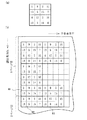
ディザ法とは、画像データの階調値と所定のディザマトリックスの閾値との大小関係に応じてハーフトーン処理を行う方法をいう。画像データの方が、ディザマトリックスよりもサイズが大きいため、ディザ法では、ディザマトリックスを所定の配置で各画素に対応付けてハーフトーン処理を行うのが通常である。ディザ法によるハーフトーン処理の様子を図16に示した。図16(a)がディザマトリックスの例である。図16(b)には、各画素へのディザマトリックスを方眼状に配置した例を示した。
【0022】
一般にディザマトリックスは単一のマトリックス内でドットの分散性が確保されるように設定される。従って、図16(b)の領域M1,M2に示すようにページごとに独立にディザマトリックスを配置した場合、両者の境界部分ではドットの分散性が十分に確保できない場合がある。これに対し、本発明の画像処理装置では、図16(b)の領域M3に示すようにディザマトリックスを境界を挟んで配置することを許容するため、境界部分でもドットの分散性を十分に確保することができ、高画質な画像処理を実現することができる。
【0023】
ディザ法によりハーフトーン処理を行う画像処理装置においては、
前記入力手段は、さらに前記複数ページのデータを、一つのまとまった画像データとして処理する長尺モードの指示およびページ区切りデータをも入力する手段であり、
前記ハーフトーン手段は、
前記ディザマトリックスと画素との対応関係を記憶する配置記憶手段と、
前記区切りデータの入力に伴って該対応関係の初期化を行う初期化手段と、前記長尺モードの指示が入力されている場合には、該初期化を禁止する禁止手段とを備えるものとすることもできる。
【0024】
こうすれば、長尺モードの指示の入力に応じて、使用者の意図に応じた適切な画像処理を実現することができるとともに、両モードにおけるハーフトーン処理をそれぞれ容易に実現することができる。
【0025】
本発明は、以下に示す通り、上記画像処理装置と主要部を同一にする印刷装置の発明として構成することもできる。
つまり、本発明の印刷装置は、
複数ページに亘る画像データに基づいて、該複数ページ以上の大きさの印刷媒体にドットを形成して画像を印刷する印刷装置であって、
前記画像データを入力する入力手段と、
各ページの境界を挟んだ前後のページ間で連続性を確保した態様で、前記画像データを各画素ごとにハーフトーン処理するハーフトーン手段と、
該ハーフトーン結果に基づいて、各画素ごとにドットを形成するドット形成手段とを備える印刷装置である。
【0026】
本発明は以下に示す画像処理方法の発明として構成することもできる。
つまり、本発明の画像処理方法は、
複数ページに亘る画像データを各画素毎にハーフトーン処理する画像処理方法であって、
(a) 前記画像データを入力する工程と、
(b) 各ページの境界を挟んだ前後のページ間で連続性を確保した態様で、前記画像データを各画素ごとにハーフトーン処理する工程とを備える画像処理方法である。
かかる画像処理方法によれば、先に印刷装置として説明したのと同様の作用により、画質を向上することができる。
【0027】
また、本発明は以下に示す記録媒体の発明として構成することもできる。
本発明の第1の記録媒体は、
複数ページに亘る画像データを各画素毎にハーフトーン処理するためのプログラムをコンピュータ読みとり可能に記録した記録媒体であって、
前記画像データを入力する機能と、
該画像データと処理対象たる着目画素のハーフトーン結果との誤差を、ページが同一であるか否かに関わりなく、前記着目画素に対して所定の相対的位置にある画素に拡散する誤差拡散法により、前記画像データを各画素ごとにハーフトーン処理する機能とを実現するプログラムを記録した記録媒体である。
【0028】
本発明の第2の記録媒体は、
複数ページに亘る画像データを各画素毎にハーフトーン処理するためのプログラムをコンピュータ読みとり可能に記録した記録媒体であって、
前記画像データを入力する機能と、
ディザマトリックスを前記境界を挟んで配置することを許容したディザ法により、前記画像データを各画素ごとにハーフトーン処理する機能とを実現するプログラムを記録した記録媒体である。
かかる記録媒体に記録されたプログラムが実行されることにより、先に説明した高画質な画像処理を実現することができる。
【0029】
なお、記憶媒体としては、フレキシブルディスクやCD−ROM、光磁気ディスク、ICカード、ROMカートリッジ、パンチカード、バーコードなどの符号が印刷された印刷物、コンピュータの内部記憶装置(RAMやROMなどのメモリ)および外部記憶装置等、コンピュータが読取り可能な種々の媒体を利用できる。また、上述のコンピュータプログラムを通信経路を介してコンピュータに供給するプログラム供給装置としての態様も含む。
【0030】
【発明の実施の形態】
以下、本発明の実施の形態について、実施例に基づき説明する。
(1)装置の構成:
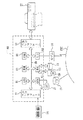
図1は、本発明の実施例としての画像処理装置および印刷装置の構成を示すブロック図である。図示するように、コンピュータ90にカラープリンタ22とが接続されている。このコンピュータ90に所定のプログラムがロードされ実行されることにより画像処理装置として機能するとともにん、プリンタ22と併せて印刷装置として機能する。このコンピュータ90は、プログラムに従って各種演算処理を実行するCPU81、ROM82、RAM83を中心に、バス80により相互に接続された次の各部を備える。入力インターフェイス84はキーボード14などからの信号の入力を司り、出力インタフェース85は、プリンタ22へのデータの出力を司る。CRTC86は、カラー表示可能なCRT21への信号出力を制御し、ディスクコントローラ(DDC)87は、ハードディスク16やCD−ROMドライブ15あるいは図示しないフレキシブルディスクドライブとの間のデータの授受を制御する。ハードディスク16には、RAM83にロードされて実行される各種プログラムやデバイスドライバの形式で提供される各種プログラムなどが記憶されている。
【0031】
このほか、バス80には、シリアル入出力インタフェース(SIO)88が接続されている。このSIO88は、モデム18に接続されており、モデム18を介して、公衆電話回線PNTに接続されている。コンピュータ90は、このSIO88およびモデム18を介して、外部のネットワークに接続されており、特定のサーバーSVに接続することにより、種々のプログラムをハードディスク16にダウンロードすることも可能である。また、必要なプログラムをフレキシブルディスクFDやCD−ROMによりロードし、コンピュータ90に実行させることも可能である。
【0032】
プリンタ22はインクジェットプリンタである。詳細な構成は後述するが、インクを吐出するためのノズルを複数備えたヘッドを印刷用紙の一方向に往復動する主走査を行うとともに、主走査と直交する方向にヘッドと印刷用紙とを相対的に移動する副走査を行うことによって画像を印刷する。
【0033】
図2は印刷装置のソフトウェアの構成を示すブロック図である。コンピュータ90では、所定のオペレーティングシステムの下で、アプリケーションプログラム95が動作している。オペレーティングシステムには、ビデオドライバ91やプリンタドライバ96が組み込まれており、アプリケーションプログラム95からはこれらのドライバを介して、プリンタ22に転送するための画像データFNLが出力される。アプリケーションプログラム95は、キーボード14などからの指示に従って、例えば横断幕のような大判の印刷媒体に印刷するための画像を生成するとともに、ビデオドライバ91を介して画像をCRTディスプレイ21に画像を表示している。アプリケーションプログラム95で生成される画像データORGは、レッド(R),グリーン(G),ブルー(B)の3色の色成分からなるデータである。
【0034】
このアプリケーションプログラム95が、印刷命令を発すると、コンピュータ90のプリンタドライバ96が、画像データORGをアプリケーションプログラム95から受け取る。アプリケーションプログラム95で生成した大判の印刷媒体用の画像データは膨大な量であるため、まとめてプリンタドライバ96に転送することはできない。オペレーティングシステム上の制限に従って、アプリケーションプログラム95は画像データを所定の大きさのページに分割して順次プリンタドライバ96に転送する。
【0035】
プリンタドライバ96の内部には、色補正モジュール99、ハーフトーンモジュール100、送り量設定部101、ラスタライザ102が備えられている。色補正モジュール99は、予め用意された色補正テーブルLUTに従って、画像データORGの色成分をR,G,Bからプリンタ22が表現可能な色成分(ここではシアン、マゼンタ、イエロ、ブラックの各色)に補正する。本実施例のプリンタ22は各画素ごとにはドットのオン・オフの2値しか採り得ない。従って、ハーフトーンモジュール100は、プリンタ22で形成するドットの分布によって補正された画像データの階調値を表現できるように誤差拡散法を用いて各画素ごとのドットのオン・オフを設定する。誤差拡散法とは、各画素ごとのドットのオン・オフに応じて生じた濃度誤差を周辺の未処理の画素に拡散することによって、全体として濃度誤差が極小のハーフトーン処理を実現する方法である。ハーフトーンモジュール100は、各画素で生じた誤差を誤差バッファEBに記憶しつつ、誤差拡散法によるハーフトーン処理を実行する。
【0036】
送り量設定部101は、印刷モードに応じて副走査量の設定を行う。本実施例の印刷装置は印刷モードとして、後述する通り、大判の印刷媒体に一つの連続した画像を印刷する長尺印刷モードと、アプリケーションから指定された各ページごとに画像を印刷する通常印刷モードとがある。それぞれの印刷モードに対応して各ページの副走査量は予め送り量テーブルSSに設定されている。送り量設定部101は、この送り量テーブルを参照してそれぞれの印刷モードに応じた送り量を設定する。また、副走査量の設定に基づいて、プリンタ22の各ノズルの位置を判定し、印刷すべきラスタを選択する。
【0037】
ラスタライザ210は、ヘッドの主走査方向に合わせて各ラスタの印刷データをヘッドに出力する順序に並べ替える。プリンタドライバ96は、以上の処理を施された画像データおよび副走査の送り量を指定する送り量データを印刷データFNLとしてプリンタ22に出力する。
【0038】
プリンタ22では、入力部201がコンピュータ90から出力された印刷データFNLを受け取り、バッファ202に一時的に蓄える。バッファ202のデータは主走査部203に出力される。主走査部203は、ヘッドの主走査を行いつつ、印刷データに基づいてインクを吐出する。また、主走査部203によりラスタが形成されると、副走査部204がプリンタドライバ96から指定された副走査量で印刷用紙を搬送する。入力部201は、主走査部203および副走査部204が印刷を実行している間に残りの部分のデータを逐次入力する。
【0039】
次に、図3によりプリンタ22の概略構成を説明する。図示するように、このプリンタ22は、紙送りモータ23によって用紙Pを搬送する機構と、キャリッジモータ24によってキャリッジ31をプラテン26の軸方向に往復動させる機構と、キャリッジ31に搭載された印字ヘッド28を駆動してインクの吐出およびドット形成を行う機構と、これらの紙送りモータ23,キャリッジモータ24,印字ヘッド28および操作パネル32との信号のやり取りを司る制御回路40とから構成されている。
【0040】
キャリッジ31をプラテン26の軸方向に往復動させる機構は、プラテン26の軸と並行に架設されキャリッジ31を摺動可能に保持する摺動軸34と、キャリッジモータ24との間に無端の駆動ベルト36を張設するプーリ38と、キャリッジ31の原点位置を検出する位置検出センサ39等から構成されている。
【0041】
なお、このキャリッジ31には、黒インク(K)用のカートリッジ71とシアン(C)、マゼンタ(M)、イエロ(Y)の3色のインクを収納したカラーインク用カートリッジ72が搭載可能である。キャリッジ31の下部の印字ヘッド28には計4個のインク吐出用ヘッド61ないし64が形成されている。キャリッジ31にこれらのインクカートリッジ71、72を上方から装着すると、各カートリッジから吐出用ヘッド61ないし64へのインクの供給が可能となる。
【0042】
本実施例のプリンタ22は印刷用紙Pとして単票紙またはロール紙を供給可能である。図示を省略したが、ロール紙は保持部に軸支されてプリンタ22に供給される。画像の印刷が終了すると、ユーザがロール紙の切断を行う。切断は、制御回路40からの信号によって自動的に用紙の切断を行う機構を設けてもよい。本実施例のプリンタ22はロール紙を用いることにより、数十メートルに亘る画像を印刷することができる。
【0043】
図4は、インク吐出用ヘッド61〜64におけるインクジェットノズルNzの配列を示す説明図である。これらのノズルの配置は、各色ごとにインクを吐出する4組のノズルアレイから成っており、48個のノズルNzが一定のノズルピッチkで千鳥状に配列されている。各ノズルアレイの副走査方向の位置は互いに一致している。本実施例のノズルピッチkは6ドット分に相当する。
【0044】
インクの吐出およびドット形成を行う機構について説明する。図5はインク吐出用ヘッド28の内部の概略構成を示す説明図である。図示の都合上、イエロのヘッドについては図示を省略した。各色のヘッド61ないし64に設けられた48個のノズルNzには、ノズルNzまでインクを導くインク通路68に接する位置に各ノズル毎にピエゾ素子PEが配置されている。ピエゾ素子PEとノズルNzとの構造を詳細に示したのが図5である。ピエゾ素子PEは、周知のように、電圧の印加により結晶構造が歪み、極めて高速に電気−機械エネルギの変換を行う素子である。ピエゾ素子PEの両端に設けられた電極間に所定時間幅の電圧を印加すると、図示するように、ピエゾ素子PEが電圧の印加時間だけ伸張し、インク通路68の一側壁を変形させる。この結果、インク通路68の体積はピエゾ素子PEの伸張に応じて収縮し、この収縮分に相当するインクが、粒子Ipとなって、ノズルNzの先端から高速に吐出される。このインク粒子Ipがプラテン26に装着された用紙Pに染み込むことにより印刷が行われる。
【0045】
次にプリンタ22の制御回路40の内部構成を説明する。図6は制御回路40の内部構成を示す説明図である。図示する通り、この制御回路40の内部には、CPU41,PROM42,RAM43の他、コンピュータ90とのデータのやりとりを行うPCインタフェース44と、紙送りモータ23、キャリッジモータ24および操作パネル32などとの信号をやりとりする周辺入出力部(PIO)45と、計時を行うタイマ46と、ヘッド61〜64にドットのオン・オフの信号を出力する駆動用バッファ47などが設けられており、これらの素子および回路はバス48で相互に接続されている。また、制御回路40には、所定周波数で各ノズルのピエゾ素子PEを駆動するための駆動波形を出力する発信器51、および発信器51からの出力をヘッド61〜64に分配する分配器55も設けられている。
【0046】
制御回路40は、コンピュータ90で処理された印刷データを受け取り、これを一時的にRAM43に蓄え、所定のタイミングで駆動用バッファ47に出力する。駆動用バッファ47からは、各ノズルごとにドットのオン・オフを示すデータが分配出力器55に出力される。この結果、ドットを形成すべきノズルに対してはピエゾ素子PEを駆動するための駆動波形が出力され、ドットが形成される。
【0047】
なお、本実施例では、上述の通りピエゾ素子PEを用いてインクを吐出するヘッドを備えたプリンタ22を用いているが、他の方法によりインクを吐出するプリンタを用いるものとしてもよい。例えば、インク通路に配置したヒータに通電し、インク通路内に発生する泡(バブル)によりインクを吐出するタイプのプリンタに適用するものとしてもよい。インクを吐出してドットを形成する他、いわゆる熱転写型のプリンタ、昇華型のプリンタ、ドットインパクト型のプリンタなど種々のタイプのプリンタに適用することも可能である。
【0048】
(2)印刷制御:
次に本実施例における印刷の制御処理について説明する。ここでは、大判の印刷媒体に画像を印刷する処理について説明する。本実施例では、かかる場合の印刷モードとして通常モードと長尺モードとを備えている。通常モードにおける画像の印刷の様子を図7(a)に示す。図示する通り、各ページごとに余白を設けて画像が印刷される。長尺モードにおける画像の印刷の様子を図7(b)に示す。長尺モードでは、Nページ(Nは2以上の整数)に分割されてアプリケーションプログラムから受け渡された画像を各ページ間で余白を設けることなく印刷用紙Pに印刷して連続画像を印刷する。
【0049】
印刷モードは印刷装置のユーザが指定することができる。長尺モードでの印刷は、大判の画像をアプリケーションプログラムで生成した場合に選択される。アプリケーションプログラムを実行するのはコンピュータ90内のCPU81である。アプリケーションプログラムを実行するCPU81は画像データを所定サイズのページに分割して、ページサイズなどのデータとともに一旦RAM83に記憶する。
【0050】
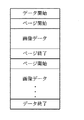
アプリケーションプログラムから提供される一連のデータの構造を図8に示す。図示する通り、一連のデータの先頭には、「データ開始」を示すコードが付される。その後、各ページの開始を示すコードが付され、続いて該ページの画像データが提供される。各ページの終わりには、ページ終了を示すコードが付される。一連のデータの末尾には、「データ終了」を示すコードが付される。アプリケーションプログラムからはかかる構造でデータが提供されるため、ページ終了を示すコードを入力した時点では、次のページが存在するか否かを判定することはできない。なお、ページ開始およびページ終了を示すコードを、以下、まとめて区切りデータと呼ぶものとする。
【0051】
一方、CPU81は、プリンタ22を駆動して印刷を実行するためのプログラムであるプリンタドライバプログラムをも実行する。プリンタドライバプログラムは、アプリケーションプログラムからの印刷指示によって起動される。プリンタドライバプログラムを実行する際のCPU81の処理の一部である印刷データ生成処理の内容を図9に示す。
【0052】
この処理が開始されると、CPU81は画像データおよび印刷モードの入力を行う(ステップS100)。画像データは、図8に示した通り、各ページに分割され、R,G,Bの階調値によって表現されたデータである。CPU81は、画像データの入力とともに区切りデータ等も入力する。CPU81は画像データについて、色補正処理を行う(ステップS110)。色補正処理とは、画像データを特定するR,G,Bの色成分を各画素ごとにプリンタ22で使用可能なC,M,Y,Kの色成分に補正する処理をいう。この処理は、R,G,Bの色系で表された色相に対してC,M,Y,Kの色成分を与える色補正テーブルLUTを用いて行われる。色補正処理の内容は周知であるため、詳細な説明を省略する。
【0053】
その後、CPU81は色補正された画像データのハーフトーン処理を行う(ステップS110)。ハーフトーン処理の内容を図10のフローチャートに示す。本実施例では、誤差拡散法によるハーフトーン処理を実行する。ハーフトーン処理としては、他にディザ法による処理が知られており、印刷モードに応じて、誤差拡散法による処理とディザ法による処理とを使い分けるものとしてもよい。
【0054】
ハーフトーン処理ルーチンが開始されると、CPU81は、画像データを入力する(ステップS140)。ここで入力される画像データは、色補正処理を施され、各画素ごとにC,M,Y,Kの各色につき256階調の階調値を有するデータである。ページの境界部分では、CPU81は画像データとともに区切りデータをも入力する。次に、CPU81は、長尺モードが指定されているか否かを判定する(ステップS140)。長尺モードでない場合、つまり通常モードが指定されている場合には、さらに改ページがされたか否かを判定する(ステップS142)。改ページは、区切りデータを入力したか否かによって判定することができる。
【0055】
CPU81は、以上の判定に基づき、通常モードが指定されており、かつ改ページがされた場合にのみ誤差バッファの初期化を行う(ステップS146)。誤差バッファとは、誤差拡散法でハーフトーン処理を実行する際に、各画素から未処理の画素に拡散すべき濃度誤差を記憶しておくバッファをいう。誤差バッファに記憶されるべき内容については後述する。上記条件に該当しない場合には、CPU81は誤差バッファの初期化を行わない。例えば長尺モードが指定された場合には、改ページが指示されたか否かに関わらず誤差バッファの初期化を行わない。
【0056】
誤差拡散法では、ドットのオン・オフの判定済みの画素で生じた局所的な濃度誤差を所定の割合で周辺の未処理の画素に拡散する。ドットのオン・オフを判定しようとしている着目画素は、処理済みの画素から拡散されてきた誤差を階調データに反映した上で、ドットのオン・オフを判定する。この着目画素でオン・オフを判定した結果生じた濃度誤差はさらに周辺の未処理の画素に拡散される。
【0057】
かかる手順で各画素についてドットのオン・オフを判定するため、CPU81は、画像データCDに拡散誤差を反映した補正データCDXを生成する(ステップS148)。反映されるべき拡散誤差は、誤差バッファに記憶されている。
【0058】
次に、生成された補正データCDXが所定の閾値TH以上であるか否かの判定を行う(ステップS150)。補正データCDXが閾値TH以上である場合には、ドットを形成すべきと判定し、判定結果を記憶する結果値RDに、ドットの形成を意味する値1を入力する(ステップS154)。補正データCDXが閾値THよりも小さい場合には、ドットを形成すべきでないと判定し、結果値RDにドットの非形成を意味する値0を入力する(ステップS152)。所定の閾値THはドットのオン・オフを判定する基準となる値であり、いずれの値に設定してもよい。本実施例では、画像データが取り得る256階調の中間の値、つまり128に閾値を設定した。
【0059】
ドットのオン・オフを決定すると、CPU81は、結果値RDに基づいて誤差計算および誤差拡散処理を行う(ステップS156)。誤差とは、多値化結果に応じて着目画素PPにドットがオンまたはオフされた場合に表現される濃度と、補正データCDXに基づいて表現されるべき濃度との誤差をいう。着目画素PPにドットが形成された場合に表現される濃度は、それぞれの画素に対して予め設定された濃度評価値RVに基づいて求められる。
【0060】
誤差ERRは、補正データCDXと濃度評価値RVを用いて、ERR=RV−CDXで求められる。例えば、ドットの濃度評価値が階調値255相当であるとした場合、補正データCDXが値199であるにも関わらずドットを形成したとすれば、そこには199−255=−56なる濃度誤差が生じていることになる。これは、その画素で表現される濃度が濃すぎることを意味する。
【0061】
誤差拡散とは、こうして求められた誤差に所定の重みをつけて、着目画素PP周辺の未処理の画素に拡散する処理をいう。図11に誤差を拡散する際の重みの例を示した。図示する通り、着目画素PPで生じた誤差は、主走査方向および副走査方向に数画素の未処理の領域に亘って拡散される。例えば、誤差が「−56」であれば、現在処理している画素PPの隣の画素P1には、誤差「−56」の1/4に相当する「−14」が拡散される。この誤差は、一旦誤差バッファに記憶され、次に画素P1を処理する際に、ステップS148において反映される。例えば、画素P1の階調データが値214であれば、拡散された誤差「−14」を加えて、補正データCDを値200とする。CPU81は、以上で説明した処理を全画素について実行すると(ステップS158)、ハーフトーン処理ルーチンを終了して印刷データ生成処理ルーチンに戻る。
【0062】
ここで、先に説明した通り、通常モードでは、改ページの度に誤差バッファが初期化される。従って、通常モードでは、前ページから次のページに誤差が拡散されることはない。これは、各ページごとに独立してハーフトーン処理が実行されることを意味する。一方、長尺モードでは、改ページされたか否かに関わらず誤差バッファの初期化を行わない。従って、前ページと次ページの境界付近の画素で生じた誤差は次のページにも拡散される。この様子を図13(b)に示した。図13(b)中の1ページ目に属する画素c1で生じた誤差は、2ページ目に属する画素c2を含む領域Cに拡散される。その後、誤差バッファを初期化することなく2ページ目の処理を行うため、画素c2には画素c1から拡散された誤差が反映されることになる。このように、本実施例の印刷装置は、長尺モードでは複数のページを一体的に扱ってハーフトーン処理を実行する。
【0063】
ハーフトーン処理が終了すると、CPU81はプリンタ22の副走査量を設定し、プリンタ22に転送するデータを抽出するための処理を実行する(ステップS200)。プリンタ22はインタレース方式と呼ばれる方法でドットの記録を行っており、その副走査量は送り量テーブルとしてROM82に予め記憶されている。CPU81は、このテーブルを参照して副走査量を設定するとともに、プリンタ22に転送すべきデータの抽出を実行する。つまり、副走査の送り量に基づいて、プリンタ22の各ノズルが画像データのいずれのラスタを形成すべきかを判定し、該ラスタのデータを抽出する。
【0064】
図12は、インタレース方式の一例を示す説明図である。図示の都合上、2ドットのピッチで3個のノズルを用いた例を示した。図中の丸が各ノズルにより形成されるドットを示している。丸中の番号は、十の位がドットを形成するノズル番号を意味し、一の位が何回目の主走査で記録されたかという順番を意味している。この例では、1回目の主走査において、2番ノズル、3番ノズルにより各ラスタのドットを形成する。1番ノズルではドットを形成しない。次に、3ラスタ分の副走査を行った後、2回目の主走査を行いつつ、1番ノズルから3番ノズルまでを用いて各ラスタを形成する。以後、同様に3ラスタ分の副走査と、主走査によるラスタの形成とを繰り返し実行することにより、図中の印刷領域に画像を記録する。
【0065】
かかる記録を実行する場合、CPU81は、1回目の主走査では、2番ノズルに画像データの先頭ラスタのデータを抽出して供給し、3番ノズルに先頭から3番目のラスタのデータを抽出して供給する。図中の右側に参照用に画像データのラスタ番号を付した。2回目の主走査では、1番ノズルに2番目のラスタ、2番ノズルに4番目のラスタ、3番ノズルに6番目のラスタのデータを供給する。このように、CPU81は副走査の送り量に応じて各ノズルに供給すべきラスタを抽出する。
【0066】
次に、CPU81はこうして抽出された各ノズルへの供給データをプリンタ22に転送する順序に並べ替えてラスタライズする(ステップS210)。例えば、主走査の往復動双方向で画像を印刷する場合には、主走査の方向に応じてデータの配列を逆転させる。また、各ラスタを2本のノズルを用いて形成する、いわゆるオーバラップ記録を行う場合には、一方のノズルに奇数番目の画素のデータ、他方のノズルに偶数番目の画素のデータが供給されるようにデータの並べ替えを行う。奇数番目の画素のみを形成するノズルに対しては、偶数番目の画素にマスクデータが挿入される。
【0067】
CPU81はこうして設定されたデータを、副走査の送り量のデータとともに、印刷データとしてプリンタ22に出力する(ステップS210)。これらの処理を全てのページが終了するまで繰り返し実行する(ステップS220)。なお、図9ではステップS100で各ページの画像データを全て入力するものとして示したが、色補正処理、ハーフトーン処理を実行しつつ、徐々に画像データを入力することもできる。プリンタ22は、以上の処理によってコンピュータ90から出力された送り量データおよび印刷データに基づいて、図12に示した態様で画像を印刷する。
【0068】
以上で説明した印刷装置によれば、長尺モードが指定された場合に、各ページごとに誤差バッファを初期化することなくハーフトーン処理を実行することができる。アプリケーションプログラムからページごとに分割して供給されるデータを一体的にハーフトーン処理することができる。一般に誤差拡散法は、ハーフトーン処理を開始した当初の領域ではその他の領域に比較して若干画質が低下するという短所がある。上述の印刷装置によれば、各ページごとに誤差バッファを初期化しないため、長尺モードにおいてページの境界付近で画質が低下することを回避でき、高画質な印刷を実現することができる。
【0069】
また、上述の印刷装置によれば、通常モードでは各ページごとに誤差バッファの初期化を実行する。通常モードでは各ページごとに独立した画像データが提供される。かかる場合にまでページ間で誤差の拡散を施す態様でハーフトーン処理を行うと、前ページからの誤差の影響により各ページの画質が損なわれる。本実施例の印刷装置は、改ページ時の誤差バッファの初期化の実行を、印刷モードに応じて使い分けることによって、各印刷モードに応じて高画質なハーフトーン処理を実現することができる。
【0070】
(3)第2実施例:
次に、本発明の第2実施例としての画像処理装置および印刷装置について説明する。第2実施例のハードウェア構成は、第1実施例と同じである。第2実施例は、ディザ法によるハーフトーン処理を行う点で第1実施例と相違する。第2実施例のハーフトーン処理のフローチャートを図14に示す。この処理は、第1実施例と同様、コンピュータ90に備えられたCPU81が実行する処理である。
【0071】
この処理が開始されると、CPU81は画像データCDを入力し(ステップS160)、長尺モードであるか否かおよび改ページされたか否かの判断を行う(ステップS162,S164)。長尺モードでない場合、つまり通常モードが指定されている場合において、改ページがされたときは、CPU81は、マトリックス配置の初期化を行う(ステップS166)。マトリックス配置の初期化については後述する。
【0072】
次に、CPU81は画像データの階調値CDと閾値THとの大小関係を判定する(ステップS168)。画像データCDが閾値TH以上である場合には、ドットを形成すべきと判定し、判定結果を記憶する結果値RDに、ドットの形成を意味する値1を入力する(ステップS172)。画像データCDが閾値THよりも小さい場合には、ドットを形成すべきでないと判定し、結果値RDにドットの非形成を意味する値0を入力する(ステップS170)。
【0073】
閾値THはディザマトリックスにより与えられる。ディザ法におけるドットのオン・オフの判定の考え方を図15に示す。図示の都合上、一部の画素についてのみ示す。図示する通り、画像データCDと各画素に対応するディザマトリックルの閾値とを比較し、その大小関係に応じてドットのオン・オフを決定するのである。図15では、ドットをオンにする画素をハッチングで示した。CPU81は、全画素について以上の処理を実行する(ステップS174)。
【0074】
ディザ法では、ディザマトリックスを所定の配置で画素と対応付けてハーフトーン処理を行う。図16(a)にディザマトリックスの例を示し、図16(b)にディザマトリックスと画素との対応関係を示した。この例では、4×4のディザマトリックスを方眼状に画素に対応付けた例を示した。ディザマトリックスは種々のサイズのものを適用可能である。
【0075】
ステップS166における配置の初期化処理では、改ページがされた場合に、図16(b)中の領域M1,M2に示すように、ディザマトリックスを新たに配置しなおす処理をいう。通常モードで改ページがなされた場合には、各ページごとに独立してハーフトーン処理を実行すべく、このように配置の初期化処理が行われる。これに対し、長尺モードが指定されている場合には、ページが異なっても配置の初期化は行われない。この結果、図16(b)の領域M3に示すようにディザマトリックスは境界を挟んで配置される。
【0076】
一般にディザマトリックスは単一のマトリックス内でドットの分散性が確保されるように設定される。第2実施例の画像処理装置によれば、長尺モードが指定されている場合には、このようにディザマトリックスを境界を挟んで配置することを許容するため、境界部分でもドットの分散性を十分に確保することができ、高画質な画像処理を実現することができる。
【0077】
以上で説明した印刷装置では、ドットのオン・オフの2値化を行うハーフトーン処理を実行する場合を例にとって説明した。本発明は誤差拡散法による3値化以上のハーフトーン処理にも適用可能であることはいうまでもない。
【0078】
以上で説明した印刷装置は、図9に示した処理をコンピュータで実現していることから、かかる処理を実現するためのプログラムを記録した記録媒体としての実施の態様を採ることもできる。図9に示した印刷データ生成処理をプリンタ22側のCPU41で実行することも可能である。
【0079】
以上、本発明の種々の実施例について説明してきたが、本発明はこれらに限定されるものではなく、その要旨を逸脱しない範囲で、種々の形態による実施が可能である。例えば、上記実施例で説明した種々の制御処理は、その一部または全部をハードウェアにより実現してもよい。上記実施例では、いわゆる定型サイズの用紙を主として使用するプリンタにロール紙を供給可能な補助具を取り付けて適用する場合を例にとって説明したが、ロール紙を主として用いるプリンタに適用することもできる。また、印刷媒体は、大判の画像を印刷可能な媒体であればロール紙に限定されるものではない。
【図面の簡単な説明】
【図1】実施例としての印刷装置を適用した印刷システムの概略構成図である。
【図2】ソフトウェアの構成を示す説明図である。
【図3】実施例としてのプリンタの概略構成図である。
【図4】ヘッドにおけるノズルの配置を示す説明図である。
【図5】ドットの形成原理を示す説明図である。
【図6】プリンタの制御装置の内部構成を示す説明図である。
【図7】各モードでの印刷の様子を示す説明図である。
【図8】画像データの構成を示す説明図である。
【図9】印刷データ生成処理ルーチンのフローチャートである。
【図10】ハーフトーン処理ルーチンのフローチャートである。
【図11】誤差を拡散する重みテーブルの例を示す説明図である。
【図12】ドットの形成の様子を示す説明図である。
【図13】誤差拡散法による処理の様子を示す説明図である。
【図14】第2実施例のハーフトーン処理ルーチンのフローチャートである。
【図15】ディザ法によるハーフトーン処理の考え方を示す説明図である。
【図16】画素とディザマトリックスの対応関係を示す説明図である。
【符号の説明】
14…キーボード
16…ハードディスク
18…モデム
22…カラープリンタ
23…モータ
24…キャリッジモータ
26…プラテン
28…印字ヘッド
31…キャリッジ
32…操作パネル
34…摺動軸
36…駆動ベルト
38…プーリ
39…位置検出センサ
40…制御回路
45…入出力部
46…タイマ
47…駆動用バッファ
48…バス
51…発信器
55…分配出力器
61〜64…インク吐出用ヘッド
68…インク通路
71…カートリッジ
72…カラーインク用カートリッジ
80…バス
81…CPU
82…ROM
83…RAM
84…入力インターフェイス
85…出力インタフェース
87…ディスクコントローラ
88…シリアル入出力インタフェース
90…コンピュータ
91…ビデオドライバ
95…アプリケーションプログラム
96…プリンタドライバ
99…色補正モジュール
100…ハーフトーンモジュール
101…送り量設定部
102…ラスタライザ
201…入力部
202…バッファ
203…主走査部
204…副走査部
210…ラスタライザ[0001]
BACKGROUND OF THE INVENTION
The present invention relates to an image processing apparatus and an image processing method that perform halftone processing on image data over a plurality of pages as coherent image data, a printing apparatus to which the image processing technology is applied, and a program for executing the image processing. The present invention relates to a recorded recording medium.
[0002]
[Prior art]
Conventionally, as an output device of a computer, an ink jet printer for recording an image by forming dots with several colors of ink ejected from a plurality of nozzles provided in a head has been proposed. Widely used for printing with multiple colors and multiple gradations. In such a printer, it is possible to print an image on a large-sized printing medium such as roll paper in addition to printing on a so-called single sheet (hereinafter, such printing is referred to as long printing). For example, an image can be printed on a print medium extending over several tens of meters such as a banner.
[0003]
Generally, there is a limit to the amount of data that can be handled by an application program that provides image data. Therefore, when performing long printing, the printer driver is usually supplied with printing data divided into a plurality of pages. During normal printing, there are margins between multiple pages, but in long printing, by eliminating this margin, you can receive continuous data printing while receiving data divided into multiple pages. Is possible.
[0004]
By the way, in an inkjet printer, normally, only binary values of dot on / off can be expressed for each pixel. Therefore, the gradation of the image data is expressed by the distribution of dots. In order to realize such expression, the process of setting on / off of dots of each pixel based on the gradation value of the image data is referred to as halftone process. In recent years, multi-value printers that can express three or more gradation values for each pixel by forming dots using dots having different ink weights or inks having different densities have been proposed. Even in a multi-value printer, the gradation value that can be expressed for each pixel is lower than the gradation value of the image data, so various gradation values are expressed by dot distribution after halftone processing. is doing. As such halftone processing methods, an error diffusion method and a dither method are known.
[0005]
[Problems to be solved by the invention]
When performing long printing, as described above, image data is supplied to the printer driver in a state of being divided into a plurality of pages. From the application, image data is supplied with a code indicating the start and end of each page, but the printer driver knows the total number of pages until a code indicating the end of the image data is input. Can not. Under such circumstances, in order to smoothly execute image processing and printing in parallel with image data input, conventionally, long-length printing has performed image processing and printing independently for each page.
[0006]
However, long printing is performed by dividing image data originally created as one into a plurality of pages without considering continuity of images. Therefore, image processing and printing are performed independently for each page, resulting in degradation of image quality at the page boundary. For example, the dot distribution may change unnaturally at the page boundary, resulting in an unnatural change in gradation value. In some cases, a pseudo contour is generated due to a change in the distribution of dots.
[0007]
The present invention has been made to solve the above-described problems, and an object of the present invention is to provide a technique for improving image quality by suppressing deterioration in image quality that occurs in the vicinity of each page boundary in long printing. And
[0008]
[Means for solving the problems and their functions and effects]
In order to solve at least a part of the above-described problems, the present invention employs the following configuration.
The printing apparatus of the present invention includes:
An image processing apparatus that performs halftone processing of image data over a plurality of pages for each pixel,
Input means for inputting the image data;
The gist of the invention is to include halftone means for halftoning the image data for each pixel in a manner in which continuity is ensured between the pages before and after the boundary of each page.
[0009]
According to such an image processing apparatus, halftone processing can be executed in a mode in which continuity is ensured between previous and subsequent pages. Therefore, it is possible to suppress a decrease in image quality due to an unnatural change in the dot distribution at the page boundary, and to realize high-quality image processing.
[0010]
Here, the continuity between pages means the continuity of processing. That is, it means that halftone processing of the next page is executed while maintaining various parameters in the halftone processing of the previous page, instead of halftone processing of the preceding and succeeding pages independently. Parameters for ensuring the continuity of processing can be determined according to the content of the halftone processing.
[0011]
In the image processing apparatus of the present invention,
A mode input means for inputting an instruction of a long mode for processing the data of the plurality of pages as a single image data;
The halftone means may be means for executing halftone processing in a manner ensuring the continuity only when an instruction for the long mode is given.
[0012]
In this way, when the long mode is instructed, the high-quality image processing described above is executed. If the long mode is not designated, halftone processing is executed independently for each page. When independent image data is supplied for each page, a halftone process having continuity between pages may adversely affect the processing result of each page. According to the image processing apparatus, it is possible to realize appropriate image processing according to the user's intention in response to the input of the instruction in the long mode.
[0013]
Various methods can be applied as the halftone processing method. For example, when the error diffusion method is applied,
The halftone means is configured to detect an error between the image data and a halftone result of a target pixel to be processed regardless of whether the pages are the same or not. The image data can be halftone processed for each pixel by an error diffusion method.
[0014]
According to the halftone means, when halftone processing is performed by the error diffusion method, the error is diffused in a predetermined range regardless of whether or not the pages are the same. In other words, in the subsequent page area adjacent to the page boundary, the error is diffused from the previous page area near the boundary. According to the halftone means, continuity of processing between pages can be ensured in this way.
[0015]
The reason why the image quality is improved by the halftone means according to the above aspect will be described. FIG. 13 is an explanatory diagram showing a state of halftone processing by the error diffusion method. FIG. 13A shows a region where errors are diffused. It is assumed that the density error generated as a result of determining whether dots are turned on or off for the pixel PP is diffused to unprocessed pixels showing hatching. FIG. 13B shows the order in which halftone processing is executed by the error diffusion method for each pixel constituting the image data and the region where the error is diffused. For image data in which pixels are arranged two-dimensionally, processing proceeds in the main scanning direction from the upper left pixel in the figure, and after reaching the end of each raster, processing is performed in the order of shifting to the raster adjacent in the sub-scanning direction. Shall be performed. The order of processing is indicated by arrows near the center of the figure.
[0016]
When processing is performed in this order, for example, the error generated in the pixel a1 and the error generated in the pixel a2 are diffused to the pixel a3 in the drawing. On the other hand, the error generated in the pixels b1 to b7 is reflected in the pixel b8 in the drawing. This means that the dot of the pixel a3 contributes to the gradation expression of the three pixels included in the area A, and the dot of the pixel b8 contributes to the gradation expression of the eight pixels included in the area B. Conversely, it can be said that the pixels a1 and a2 contribute to the gradation expression of the pixel a3, and the pixels b1 to b7 contribute to the gradation expression of the pixel b8. Clearly, region A is narrower than region B. As for the region B, if it is considered that the error diffusing error in the pixels b1 to b7 is also indirectly diffusing the error in the pixel b8, the region contributing to the gradation expression of the pixel b8 becomes wider. Since the halftone process is a process of performing gradation expression with the distribution of dots within a certain area, the larger the area that can contribute to the gradation expression of each pixel, the smaller the density error can be. Therefore, in the example of FIG. 13, the gradation can be appropriately expressed in the region B than in the region A. As described above, in the error diffusion method, the area that can contribute to the gradation expression cannot be made sufficiently wide in the initial area where the processing is started, and the image quality of the halftone process is not as high as that in the other areas.
[0017]
When halftone processing is executed for each page, an area in which an error cannot be sufficiently diffused occurs in an area near the boundary between pages, and image quality is deteriorated. On the other hand, according to the image processing apparatus of the present invention, as shown in a region C in the figure, errors generated in pixels near the boundary between the previous page and the next page are diffused to the next page. For example, the error generated in the pixel c1 belonging to the first page in FIG. 13B is diffused to the region C including the pixel c2 belonging to the second page. As a result, even in the area near the page boundary, it is possible to secure a sufficient area that can contribute to gradation expression like other areas, minimizing errors and improving image quality. .
[0018]
In an image processing apparatus that performs halftone processing by an error diffusion method,
The input means is means for inputting a long mode instruction and page break data for further processing the data of the plurality of pages as a single image data,
The halftone means includes
Error storage means for temporarily storing the diffused error;
Initialization means for initializing the error storage means in accordance with the input of the delimiter data;
In the case where an instruction for the long mode is input, a prohibiting unit for prohibiting the initialization may be provided.
[0019]
In this way, appropriate image processing according to the user's intention can be realized in response to the input of the instruction in the long mode, and halftone processing in both modes can be easily realized.
[0020]
In the image processing apparatus of the present invention,
The halftone means may be means for performing a halftone process by a dither method that allows a dither matrix to be arranged across the boundary.
[0021]
The dither method is a method of performing halftone processing according to the magnitude relationship between the gradation value of image data and a threshold value of a predetermined dither matrix. Since the image data is larger in size than the dither matrix, in the dither method, the halftone process is usually performed by associating the dither matrix with each pixel in a predetermined arrangement. The state of halftone processing by the dither method is shown in FIG. FIG. 16A shows an example of a dither matrix. FIG. 16B shows an example in which the dither matrix for each pixel is arranged in a grid pattern.
[0022]
In general, the dither matrix is set so as to ensure the dispersibility of dots within a single matrix. Accordingly, when the dither matrix is arranged independently for each page as shown in the areas M1 and M2 in FIG. 16B, there may be a case where sufficient dot dispersibility cannot be secured at the boundary portion between the two. On the other hand, in the image processing apparatus of the present invention, as shown in the area M3 in FIG. 16B, the dither matrix is allowed to be arranged across the boundary, so that sufficient dot dispersibility is ensured even at the boundary portion. And high-quality image processing can be realized.
[0023]
In an image processing apparatus that performs halftone processing by the dither method,
The input means is means for inputting a long mode instruction and page break data for further processing the data of the plurality of pages as a single image data,
The halftone means includes
Arrangement storage means for storing the correspondence between the dither matrix and the pixels;
Initialization means for initializing the correspondence with the input of the delimiter data, and prohibition means for prohibiting the initialization when the instruction for the long mode is input You can also.
[0024]
In this way, appropriate image processing according to the user's intention can be realized in response to the input of the instruction in the long mode, and halftone processing in both modes can be easily realized.
[0025]
The present invention can also be configured as an invention of a printing apparatus in which the main part is the same as that of the image processing apparatus as described below.
That is, the printing apparatus of the present invention is
A printing apparatus that prints an image by forming dots on a print medium having a size of a plurality of pages or more based on image data over a plurality of pages,
Input means for inputting the image data;
Halftone means for halftoning the image data for each pixel in a manner that ensures continuity between the pages before and after the boundary of each page;
And a dot forming unit that forms dots for each pixel based on the halftone result.
[0026]
The present invention can also be configured as an invention of an image processing method described below.
That is, the image processing method of the present invention is
An image processing method for halftone processing image data over a plurality of pages for each pixel,
(A) inputting the image data;
(B) An image processing method including a step of halftoning the image data for each pixel in a manner in which continuity is ensured between pages before and after the boundary between the pages.
According to such an image processing method, the image quality can be improved by the same operation as described above as the printing apparatus.
[0027]
The present invention can also be configured as a recording medium invention described below.
The first recording medium of the present invention is
A recording medium that records a computer-readable program for halftone processing image data over a plurality of pages for each pixel,
A function of inputting the image data;
An error diffusion method for diffusing an error between the image data and a halftone result of a target pixel to be processed to a pixel at a predetermined relative position with respect to the target pixel regardless of whether or not the page is the same. Thus, the recording medium stores a program that realizes a function of performing halftone processing of the image data for each pixel.
[0028]
The second recording medium of the present invention is
A recording medium that records a computer-readable program for halftone processing image data over a plurality of pages for each pixel,
A function of inputting the image data;
The recording medium stores a program for realizing a function of performing halftone processing on the image data for each pixel by a dither method that allows a dither matrix to be arranged with the boundary interposed therebetween.
By executing the program recorded on such a recording medium, the above-described high-quality image processing can be realized.
[0029]
Storage media include flexible disks, CD-ROMs, magneto-optical disks, IC cards, ROM cartridges, punch cards, printed materials printed with codes such as bar codes, and computer internal storage devices (memory such as RAM and ROM). ) And external storage devices can be used. Moreover, the aspect as a program supply apparatus which supplies the above-mentioned computer program to a computer via a communication path is also included.
[0030]
DETAILED DESCRIPTION OF THE INVENTION
Hereinafter, embodiments of the present invention will be described based on examples.
(1) Device configuration:
FIG. 1 is a block diagram illustrating a configuration of an image processing apparatus and a printing apparatus as an embodiment of the present invention. As shown in the figure, a
[0031]
In addition, a serial input / output interface (SIO) 88 is connected to the
[0032]
The
[0033]
FIG. 2 is a block diagram illustrating a software configuration of the printing apparatus. In the
[0034]
When the
[0035]
Inside the
[0036]
The feed
[0037]
The
[0038]
In the
[0039]
Next, a schematic configuration of the
[0040]
The mechanism for reciprocating the
[0041]
The
[0042]
The
[0043]
FIG. 4 is an explanatory diagram showing the arrangement of the inkjet nozzles Nz in the ink ejection heads 61 to 64. The arrangement of these nozzles is composed of four sets of nozzle arrays for ejecting ink for each color, and 48 nozzles Nz are arranged in a staggered manner at a constant nozzle pitch k. The positions of the nozzle arrays in the sub-scanning direction coincide with each other. The nozzle pitch k in this embodiment corresponds to 6 dots.
[0044]
A mechanism for ejecting ink and forming dots will be described. FIG. 5 is an explanatory diagram showing a schematic configuration inside the
[0045]
Next, the internal configuration of the
[0046]
The
[0047]
In this embodiment, as described above, the
[0048]
(2) Print control:
Next, printing control processing in this embodiment will be described. Here, a process for printing an image on a large print medium will be described. In this embodiment, a normal mode and a long mode are provided as print modes in such a case. FIG. 7A shows how the image is printed in the normal mode. As shown, an image is printed with a margin for each page. FIG. 7B shows how the image is printed in the long mode. In the long mode, an image divided into N pages (N is an integer of 2 or more) and delivered from the application program is printed on the printing paper P without a margin between the pages, and a continuous image is printed.
[0049]
The printing mode can be specified by the user of the printing apparatus. Printing in the long mode is selected when a large image is generated by an application program. The
[0050]
The structure of a series of data provided from the application program is shown in FIG. As shown in the drawing, a code indicating “data start” is attached to the head of a series of data. Thereafter, a code indicating the start of each page is added, and then image data of the page is provided. A code indicating the end of the page is attached to the end of each page. A code indicating “data end” is attached to the end of the series of data. Since data is provided from the application program in such a structure, it is not possible to determine whether or not the next page exists when a code indicating page end is input. The codes indicating the page start and page end are hereinafter collectively referred to as delimiter data.
[0051]
On the other hand, the
[0052]
When this process is started, the
[0053]
Thereafter, the
[0054]
When the halftone processing routine is started, the
[0055]
Based on the above determination, the
[0056]
In the error diffusion method, a local density error generated in a pixel for which dot on / off has been determined is diffused to surrounding unprocessed pixels at a predetermined rate. The pixel of interest that is trying to determine whether the dot is on or off determines whether the dot is on or off after reflecting the error diffused from the processed pixel in the gradation data. The density error generated as a result of determining whether the pixel of interest is on or off is further diffused to surrounding unprocessed pixels.
[0057]
In order to determine dot on / off for each pixel in this procedure, the
[0058]
Next, it is determined whether or not the generated correction data CDX is equal to or greater than a predetermined threshold value TH (step S150). If the correction data CDX is equal to or greater than the threshold value TH, it is determined that a dot should be formed, and a
[0059]
When the dot on / off is determined, the
[0060]
The error ERR is obtained by ERR = RV−CDX using the correction data CDX and the density evaluation value RV. For example, assuming that the dot density evaluation value is equivalent to the gradation value 255, if a dot is formed even though the correction data CDX is a value of 199, a density of 199-255 = −56 is present there. An error has occurred. This means that the density expressed by the pixel is too dark.
[0061]
Error diffusion refers to a process in which a predetermined weight is given to the error thus obtained and diffused to unprocessed pixels around the pixel of interest PP. FIG. 11 shows an example of weights used when diffusing errors. As shown in the drawing, the error generated in the target pixel PP is diffused over several unprocessed areas of several pixels in the main scanning direction and the sub-scanning direction. For example, if the error is “−56”, “−14” corresponding to ¼ of the error “−56” is diffused to the pixel P1 adjacent to the currently processed pixel PP. This error is temporarily stored in the error buffer, and is reflected in step S148 when the pixel P1 is processed next. For example, if the gradation data of the pixel P1 is the value 214, the diffused error “−14” is added and the correction data CD is set to the value 200. When the
[0062]
Here, as described above, in the normal mode, the error buffer is initialized for each page break. Therefore, in the normal mode, the error is not diffused from the previous page to the next page. This means that halftone processing is performed independently for each page. On the other hand, in the long mode, the error buffer is not initialized regardless of whether a page break has occurred. Therefore, an error generated in a pixel near the boundary between the previous page and the next page is diffused to the next page. This situation is shown in FIG. The error generated in the pixel c1 belonging to the first page in FIG. 13B is diffused to the region C including the pixel c2 belonging to the second page. Thereafter, since the process for the second page is performed without initializing the error buffer, the error diffused from the pixel c1 is reflected in the pixel c2. As described above, in the long mode, the printing apparatus according to the present embodiment integrally handles a plurality of pages and executes halftone processing.
[0063]
When the halftone process ends, the
[0064]
FIG. 12 is an explanatory diagram illustrating an example of an interlace method. For convenience of illustration, an example in which three nozzles are used at a pitch of 2 dots is shown. Circles in the figure indicate dots formed by the nozzles. The number in the circle means the nozzle number where the tens place forms a dot, and the order in which the first place is recorded in the main scanning. In this example, dots of each raster are formed by the second nozzle and the third nozzle in the first main scanning. The first nozzle does not form dots. Next, after performing the sub-scan for three rasters, each raster is formed using the first nozzle to the third nozzle while performing the second main scan. Thereafter, similarly, the sub-scan for three rasters and the raster formation by the main scan are repeatedly executed to record an image in the print area in the figure.
[0065]
When executing such recording, the
[0066]
Next, the
[0067]
The
[0068]
According to the printing apparatus described above, when the long mode is designated, halftone processing can be executed without initializing the error buffer for each page. Data that is divided and supplied for each page from the application program can be halftoned integrally. In general, the error diffusion method has a disadvantage that the image quality is slightly deteriorated in the initial region where the halftone process is started compared to other regions. According to the above-described printing apparatus, since the error buffer is not initialized for each page, it is possible to avoid deterioration in image quality near the page boundary in the long mode, and to realize high-quality printing.
[0069]
Further, according to the printing apparatus described above, the error buffer is initialized for each page in the normal mode. In the normal mode, independent image data is provided for each page. In such a case, if halftone processing is performed in such a manner that error is diffused between pages, the image quality of each page is impaired due to the influence of errors from the previous page. The printing apparatus according to the present exemplary embodiment can implement high-quality halftone processing according to each printing mode by properly using the initialization of the error buffer at the time of page break according to the printing mode.
[0070]
(3) Second embodiment:
Next, an image processing apparatus and a printing apparatus as a second embodiment of the present invention will be described. The hardware configuration of the second embodiment is the same as that of the first embodiment. The second embodiment is different from the first embodiment in that halftone processing is performed by a dither method. A flowchart of the halftone process of the second embodiment is shown in FIG. This process is a process executed by the
[0071]
When this process is started, the
[0072]
Next, the
[0073]
The threshold value TH is given by a dither matrix. FIG. 15 shows the concept of dot on / off determination in the dither method. For the sake of illustration, only some pixels are shown. As shown in the figure, the image data CD is compared with a dithermatic threshold corresponding to each pixel, and dot on / off is determined according to the magnitude relationship. In FIG. 15, pixels that turn on dots are indicated by hatching. The
[0074]
In the dither method, halftone processing is performed by associating a dither matrix with pixels in a predetermined arrangement. FIG. 16A shows an example of the dither matrix, and FIG. 16B shows the correspondence between the dither matrix and the pixels. In this example, an example in which a 4 × 4 dither matrix is associated with pixels in a grid pattern is shown. Dither matrices of various sizes can be applied.
[0075]
The layout initialization process in step S166 refers to a process for newly rearranging the dither matrix as shown in areas M1 and M2 in FIG. When a page break is made in the normal mode, the layout initialization process is performed in this way so that the halftone process is executed independently for each page. On the other hand, when the long mode is designated, the layout is not initialized even if the pages are different. As a result, the dither matrix is arranged across the boundary as shown in a region M3 in FIG.
[0076]
In general, the dither matrix is set so as to ensure the dispersibility of dots within a single matrix. According to the image processing apparatus of the second embodiment, in the case where the long mode is designated, in order to allow the dither matrix to be arranged across the boundary in this way, the dot dispersibility is also increased at the boundary portion. Sufficiently high image quality processing can be realized.
[0077]
In the printing apparatus described above, the case where halftone processing for binarizing dots on / off is executed has been described as an example. Needless to say, the present invention can also be applied to halftone processing of three or more values by the error diffusion method.
[0078]
Since the printing apparatus described above implements the processing shown in FIG. 9 by a computer, it can also adopt an embodiment as a recording medium in which a program for realizing such processing is recorded. The print data generation process shown in FIG. 9 can also be executed by the CPU 41 on the
[0079]
Although various embodiments of the present invention have been described above, the present invention is not limited to these embodiments, and various embodiments can be implemented without departing from the spirit of the present invention. For example, some or all of the various control processes described in the above embodiments may be realized by hardware. In the above-described embodiment, a case where an auxiliary tool capable of supplying roll paper is attached to and applied to a printer mainly using so-called fixed-size paper is described as an example, but the present invention can also be applied to a printer mainly using roll paper. Further, the print medium is not limited to roll paper as long as it can print a large image.
[Brief description of the drawings]
FIG. 1 is a schematic configuration diagram of a printing system to which a printing apparatus as an embodiment is applied.
FIG. 2 is an explanatory diagram showing a configuration of software.
FIG. 3 is a schematic configuration diagram of a printer as an embodiment.
FIG. 4 is an explanatory diagram showing the arrangement of nozzles in the head.
FIG. 5 is an explanatory diagram showing the principle of dot formation.
FIG. 6 is an explanatory diagram illustrating an internal configuration of a printer control apparatus.
FIG. 7 is an explanatory diagram showing a state of printing in each mode.
FIG. 8 is an explanatory diagram showing a configuration of image data.
FIG. 9 is a flowchart of a print data generation processing routine.
FIG. 10 is a flowchart of a halftone processing routine.
FIG. 11 is an explanatory diagram illustrating an example of a weight table for diffusing errors.
FIG. 12 is an explanatory diagram showing how dots are formed.
FIG. 13 is an explanatory diagram showing a state of processing by an error diffusion method.
FIG. 14 is a flowchart of a halftone processing routine of the second embodiment.
FIG. 15 is an explanatory diagram showing the concept of halftone processing by the dither method.
FIG. 16 is an explanatory diagram illustrating a correspondence relationship between a pixel and a dither matrix.
[Explanation of symbols]
14 ... Keyboard
16. Hard disk
18 ... modem
22 Color printer
23 ... Motor
24 ... Carriage motor
26 ... Platen
28 ... Print head
31 ... Carriage
32 ... Control panel
34 ... Sliding shaft
36 ... Drive belt
38 ... pulley
39 ... Position detection sensor
40 ... Control circuit
45 ... Input / output section
46 ... Timer
47 ... Drive buffer
48 ... Bus
51 ... Transmitter
55 ... Distribution output device
61-64 ... Ink ejection head
68 ... Ink passage
71 ... cartridge
72. Color ink cartridge
80 ... Bus
81 ... CPU
82 ... ROM
83 ... RAM
84 ... Input interface
85 ... Output interface
87: Disk controller
88 ... Serial I / O interface
90 ... Computer
91 ... Video driver
95 ... Application program
96 ... Printer driver
99 ... Color correction module
100 ... Halftone module
101 ... Feed amount setting section
102: Rasterizer
201 ... input unit
202 ... Buffer
203 ... main scanning unit
204: Sub-scanning unit
210 ... Rasterizer
Claims (10)
前記画像データを複数ページに分割された状態で受け取る入力手段と、各ページの境界において、前ページのハーフトーン処理におけるパラメータを保持した状態で、前記前ページのハーフトーン処理におけるパラメータを使用して、次ページの前記画像データについて各画素のハーフトーン処理を行うハーフトーン手段とを備える画像処理装置。An image processing apparatus that performs halftone processing of image data over a plurality of pages for each pixel,
Input means for receiving the image data in a state of being divided into a plurality of pages, and using the parameters for the halftone processing of the previous page in a state where the parameters for the halftone processing of the previous page are held at the boundary of each page An image processing apparatus comprising: halftone means for performing halftone processing of each pixel on the image data of the next page.
前記複数ページのデータを、一つのまとまった画像データとして処理する長尺モードの指示を入力するモード入力手段を備え、
前記ハーフトーン手段は、該長尺モードの指示がなされた場合にのみ、前記連続的なハーフトーン処理を実行する手段である画像処理装置。The image processing apparatus according to claim 1,
A mode input means for inputting an instruction of a long mode for processing the data of the plurality of pages as a single image data;
The halftone means is an image processing apparatus which is means for executing the continuous halftone processing only when an instruction for the long mode is given.
前記ハーフトーン手段は、該画像データと処理対象たる着目画素のハーフトーン結果との誤差を、ページが同一であるか否かに関わりなく、前記着目画素に対して所定の相対的位置にある画素に拡散する誤差拡散法により、前記画像データを各画素ごとにハーフトーン処理する手段である画像処理装置。The image processing apparatus according to claim 1,
The halftone means is configured to detect an error between the image data and a halftone result of a target pixel to be processed regardless of whether the pages are the same or not. An image processing apparatus, which is means for halftone processing the image data for each pixel by an error diffusion method for diffusing the image data.
前記入力手段は、さらに前記複数ページのデータを、一つのまとまった画像データとして処理する長尺モードの指示およびページ区切りデータをも入力する手段であり、
前記ハーフトーン手段は、
拡散される誤差を一時的に記憶するための誤差記憶手段と、
前記区切りデータの入力に伴って該誤差記憶手段の初期化を行う初期化手段と、
前記長尺モードの指示が入力されている場合には、該初期化を禁止する禁止手段とを備える画像処理装置。The image processing apparatus according to claim 3,
The input means is means for inputting a long mode instruction and page break data for further processing the data of the plurality of pages as a single image data,
The halftone means includes
Error storage means for temporarily storing the diffused error;
Initialization means for initializing the error storage means in accordance with the input of the delimiter data;
An image processing apparatus comprising: prohibiting means for prohibiting initialization when an instruction for the long mode is input.
前記ハーフトーン手段は、ディザマトリックスを前記境界を挟んで配置することを許容したディザ法によりハーフトーン処理する手段である画像処理装置。The image processing apparatus according to claim 1,
The halftone means is an image processing apparatus which is a means for performing a halftone process by a dither method that allows a dither matrix to be arranged across the boundary.
前記入力手段は、さらに前記複数ページのデータを、一つのまとまった画像データとして処理する長尺モードの指示およびページ区切りデータをも入力する手段であり、
前記ハーフトーン手段は、
前記ディザマトリックスと画素との対応関係を記憶する配置記憶手段と、
前記区切りデータの入力に伴って該対応関係の初期化を行う初期化手段と、
前記長尺モードの指示が入力されている場合には、該初期化を禁止する禁止手段とを備える画像処理装置。The image processing apparatus according to claim 5, wherein
The input means is means for inputting a long mode instruction and page break data for further processing the data of the plurality of pages as a single image data,
The halftone means includes
Arrangement storage means for storing the correspondence between the dither matrix and the pixels;
Initialization means for initializing the correspondence with the input of the delimiter data;
An image processing apparatus comprising: prohibiting means for prohibiting initialization when an instruction for the long mode is input.
前記画像データを複数ページに分割された状態で受け取る入力手段と、
各ページの境界において、前ページのハーフトーン処理におけるパラメータを保持した状態で、前記前ページのハーフトーン処理におけるパラメータを使用して、次ページの前記画像データについて各画素のハーフトーン処理を行うハーフトーン手段と、
該ハーフトーン結果に基づいて、各画素ごとにドットを形成するドット形成手段とを備える印刷装置。A printing apparatus that prints an image by forming dots on a print medium having a size of a plurality of pages or more based on image data over a plurality of pages,
Input means for receiving the image data in a state of being divided into a plurality of pages ;
A halftone process that performs halftone processing of each pixel on the image data of the next page using the parameters of the previous page halftone process while maintaining the parameters of the previous page halftone process at the boundary of each page Tone means;
A printing apparatus comprising dot forming means for forming dots for each pixel based on the halftone result.
(a) 前記画像データを複数ページに分割された状態で受け取る工程と、
(b) 各ページの境界において、前ページのハーフトーン処理におけるパラメータを保持した状態で、前記前ページのハーフトーン処理におけるパラメータを使用して、次ページの前記画像データについて各画素のハーフトーン処理を行う工程とを備える画像処理方法。An image processing method for halftone processing image data over a plurality of pages for each pixel,
(A) receiving the image data in a state of being divided into a plurality of pages ;
(B) At the boundary of each page, with the parameters for the halftone processing of the previous page being held, the halftone processing of each pixel is performed on the image data of the next page using the parameters for the halftone processing of the previous page An image processing method.
前記画像データを複数ページに分割された状態で受け取る機能と、
各ページの境界において、前ページのハーフトーン処理における該画像データと処理対象たる着目画素のハーフトーン結果との誤差を、前記着目画素に対して所定の相対的位置にある次ページの画素に拡散する誤差拡散法により、前記画像データを各画素ごとにハーフトーン処理する機能とを実現するプログラムを記録した記録媒体。A recording medium that records a computer-readable program for halftone processing image data over a plurality of pages for each pixel,
A function of receiving the image data in a state of being divided into a plurality of pages ;
At the boundary of each page, the error between the image data in the halftone process of the previous page and the halftone result of the target pixel to be processed is diffused to the next page pixel at a predetermined relative position with respect to the target pixel. A recording medium on which is recorded a program that realizes a function of performing a halftone process on the image data for each pixel by an error diffusion method.
前記画像データを複数ページに分割された状態で受け取る機能と、
ディザマトリックスを各ページの境界を挟んで配置することを許容したディザ法により、前ページに含まれる前記画像データの画素と、次のページに含まれる前記画像データの画素と、について、ページの境界を挟んで配置された単一のディザマトリックスを使用してハーフトーン処理する機能とを実現するプログラムを記録した記録媒体。A recording medium that records a computer-readable program for halftone processing image data over a plurality of pages for each pixel,
A function of receiving the image data in a state of being divided into a plurality of pages ;
By using a dither method that allows the dither matrix to be arranged across the boundaries of each page, the image data pixels included in the previous page and the image data pixels included in the next page are page boundaries. A recording medium on which is recorded a program that realizes a halftone processing function using a single dither matrix arranged with a gap between them.
Priority Applications (5)
| Application Number | Priority Date | Filing Date | Title |
|---|---|---|---|
| JP35396498A JP3829508B2 (en) | 1998-11-27 | 1998-11-27 | Image processing apparatus, image processing method, and printing apparatus |
| US09/444,843 US7050194B1 (en) | 1998-11-27 | 1999-11-22 | Image processing apparatus, method of processing images, and printing apparatus to which image processing method is applied |
| EP99309473A EP1005221B1 (en) | 1998-11-27 | 1999-11-26 | Image processing |
| DE69940688T DE69940688D1 (en) | 1998-11-27 | 1999-11-26 | image processing |
| AT99309473T ATE428265T1 (en) | 1998-11-27 | 1999-11-26 | IMAGE PROCESSING |
Applications Claiming Priority (1)
| Application Number | Priority Date | Filing Date | Title |
|---|---|---|---|
| JP35396498A JP3829508B2 (en) | 1998-11-27 | 1998-11-27 | Image processing apparatus, image processing method, and printing apparatus |
Related Child Applications (1)
| Application Number | Title | Priority Date | Filing Date |
|---|---|---|---|
| JP2004350660A Division JP2005137019A (en) | 2004-12-03 | 2004-12-03 | Image processing apparatus, image processing method and printer |
Publications (2)
| Publication Number | Publication Date |
|---|---|
| JP2000158714A JP2000158714A (en) | 2000-06-13 |
| JP3829508B2 true JP3829508B2 (en) | 2006-10-04 |
Family
ID=18434404
Family Applications (1)
| Application Number | Title | Priority Date | Filing Date |
|---|---|---|---|
| JP35396498A Expired - Fee Related JP3829508B2 (en) | 1998-11-27 | 1998-11-27 | Image processing apparatus, image processing method, and printing apparatus |
Country Status (5)
| Country | Link |
|---|---|
| US (1) | US7050194B1 (en) |
| EP (1) | EP1005221B1 (en) |
| JP (1) | JP3829508B2 (en) |
| AT (1) | ATE428265T1 (en) |
| DE (1) | DE69940688D1 (en) |
Families Citing this family (26)
| Publication number | Priority date | Publication date | Assignee | Title |
|---|---|---|---|---|
| JP3584964B2 (en) * | 1999-10-14 | 2004-11-04 | 三菱電機株式会社 | Color conversion device and color conversion method |
| DE10038772A1 (en) * | 2000-08-09 | 2002-02-21 | Heidelberger Druckmasch Ag | Process and device for processing process steps |
| JP3661624B2 (en) * | 2000-10-06 | 2005-06-15 | セイコーエプソン株式会社 | Image processing device |
| US6999202B2 (en) | 2001-03-27 | 2006-02-14 | Polaroid Corporation | Method for generating a halftone of a source image |
| US6842186B2 (en) * | 2001-05-30 | 2005-01-11 | Polaroid Corporation | High speed photo-printing apparatus |
| DE60206039T2 (en) * | 2001-05-30 | 2006-06-22 | Polaroid Corp., Waltham | HIGH-SPEED PHOTOGRAPH UNIT |
| US6937365B2 (en) | 2001-05-30 | 2005-08-30 | Polaroid Corporation | Rendering images utilizing adaptive error diffusion |
| US6906736B2 (en) * | 2002-02-19 | 2005-06-14 | Polaroid Corporation | Technique for printing a color image |
| JP3823846B2 (en) * | 2002-02-27 | 2006-09-20 | ブラザー工業株式会社 | Spool file processing apparatus, program, and recording medium |
| JP4272843B2 (en) | 2002-04-25 | 2009-06-03 | キヤノン株式会社 | Image processing apparatus and image processing method |
| JP3913220B2 (en) * | 2003-01-24 | 2007-05-09 | キヤノン株式会社 | Image forming apparatus, image repeat method, layout method, and storage medium storing computer-readable program and program |
| US7283666B2 (en) | 2003-02-27 | 2007-10-16 | Saquib Suhail S | Digital image exposure correction |
| US8773685B2 (en) * | 2003-07-01 | 2014-07-08 | Intellectual Ventures I Llc | High-speed digital image printing system |
| US7265872B2 (en) * | 2003-10-15 | 2007-09-04 | International Business Machines Corporation | Error diffusion with averaged directional biases |
| JP4293044B2 (en) * | 2004-04-21 | 2009-07-08 | ブラザー工業株式会社 | Image forming apparatus, image forming method, and image forming program |
| JP4297033B2 (en) * | 2004-09-30 | 2009-07-15 | セイコーエプソン株式会社 | Image processing apparatus that performs multi-value conversion for each pixel |
| JP4635762B2 (en) * | 2005-02-09 | 2011-02-23 | セイコーエプソン株式会社 | Image processing apparatus and printing apparatus for bidirectional printing |
| JP4766302B2 (en) * | 2005-03-22 | 2011-09-07 | オムロン株式会社 | Image processing apparatus and method, recording medium, and program |
| JP4882926B2 (en) * | 2007-08-31 | 2012-02-22 | セイコーエプソン株式会社 | Image data processing apparatus and image data processing method |
| JP2012179823A (en) * | 2011-03-02 | 2012-09-20 | Seiko Epson Corp | Device, method and program for print control |
| US8913288B2 (en) * | 2012-03-30 | 2014-12-16 | Konica Minolta Laboratory U.S.A., Inc. | Method and system for changing physical page properties in a priting application |
| CN102800061B (en) * | 2012-06-26 | 2016-05-11 | 重庆医科大学 | The quick self-adapted optimization method of digital picture under high illumination |
| CN102800060B (en) * | 2012-06-26 | 2016-05-11 | 重庆医科大学 | The quick self-adapted optimization method of digital picture under low-light (level) |
| JP6102206B2 (en) * | 2012-11-19 | 2017-03-29 | セイコーエプソン株式会社 | Printing apparatus, printing method, and program |
| JP2018533322A (en) * | 2016-01-29 | 2018-11-08 | ヒューレット−パッカード デベロップメント カンパニー エル.ピー.Hewlett‐Packard Development Company, L.P. | Error diffusion |
| JP7109324B2 (en) * | 2018-09-21 | 2022-07-29 | 株式会社Screenホールディングス | Printing method and printing device |
Family Cites Families (9)
| Publication number | Priority date | Publication date | Assignee | Title |
|---|---|---|---|---|
| JPS61261968A (en) | 1985-05-15 | 1986-11-20 | Dainippon Screen Mfg Co Ltd | Method and device for generating dot |
| JPH0354924Y2 (en) * | 1985-10-14 | 1991-12-05 | ||
| JP2547771B2 (en) | 1987-06-11 | 1996-10-23 | キヤノン株式会社 | Image processing method |
| US4958236A (en) | 1987-06-11 | 1990-09-18 | Canon Kabushiki Kaisha | Image processing method and apparatus therefor |
| JPH04178965A (en) * | 1990-11-14 | 1992-06-25 | Sharp Corp | Device for initializing storage medium |
| US5768411A (en) | 1996-02-26 | 1998-06-16 | Seiko Epson Corporation | Dispersed-dot dither with improved light-color smoothness |
| US6175424B1 (en) * | 1996-12-20 | 2001-01-16 | Canon Kabushiki Kaisha | Image processing apparatus and image processing method |
| US6320675B1 (en) * | 1997-07-15 | 2001-11-20 | Canon Kabushiki Kaisha | Image processing apparatus and method and storage medium |
| JP3639703B2 (en) * | 1997-11-14 | 2005-04-20 | キヤノン株式会社 | Inkjet recording apparatus and inkjet recording method |
-
1998
- 1998-11-27 JP JP35396498A patent/JP3829508B2/en not_active Expired - Fee Related
-
1999
- 1999-11-22 US US09/444,843 patent/US7050194B1/en not_active Expired - Fee Related
- 1999-11-26 AT AT99309473T patent/ATE428265T1/en not_active IP Right Cessation
- 1999-11-26 DE DE69940688T patent/DE69940688D1/en not_active Expired - Lifetime
- 1999-11-26 EP EP99309473A patent/EP1005221B1/en not_active Expired - Lifetime
Also Published As
| Publication number | Publication date |
|---|---|
| JP2000158714A (en) | 2000-06-13 |
| US7050194B1 (en) | 2006-05-23 |
| EP1005221A2 (en) | 2000-05-31 |
| ATE428265T1 (en) | 2009-04-15 |
| EP1005221B1 (en) | 2009-04-08 |
| EP1005221A3 (en) | 2002-04-17 |
| DE69940688D1 (en) | 2009-05-20 |
Similar Documents
| Publication | Publication Date | Title |
|---|---|---|
| JP3829508B2 (en) | Image processing apparatus, image processing method, and printing apparatus | |
| EP0830948B1 (en) | Ink jet printer and head unit of the same | |
| US20060274098A1 (en) | Ink jet printing system | |
| US7798589B2 (en) | Image forming apparatus, image processing apparatus, and control method therefor | |
| JP4385626B2 (en) | Image processing apparatus, image processing method, and image processing program | |
| JP5072349B2 (en) | Image forming apparatus and control method thereof | |
| JP3981480B2 (en) | Printing apparatus and recording medium | |
| JP4501826B2 (en) | Printing device | |
| JP3687381B2 (en) | Printing apparatus, printing method, and recording medium | |
| JP2004174751A (en) | Ink jet recorder | |
| JP4075241B2 (en) | Printing apparatus, printing method, and recording medium | |
| JP4154865B2 (en) | Printing with multiple pixels as one unit of gradation reproduction | |
| JP2006116975A (en) | Printing system for continuous printing | |
| JP3729199B2 (en) | Printing apparatus, printing method, and recording medium | |
| JP3915521B2 (en) | Printing that suppresses blurring of contours | |
| JP4097170B2 (en) | Image processing apparatus, image processing method, and recording medium | |
| JP3757650B2 (en) | Image processing device | |
| JP2007008176A (en) | Printer, printer control program, printer control method, apparatus for generating printing data, program for generating printing data, and method for generating printing data | |
| JP4535081B2 (en) | Printing apparatus and recording medium | |
| JP2963032B2 (en) | Printing apparatus and printing method | |
| JP2005137019A (en) | Image processing apparatus, image processing method and printer | |
| JP3797097B2 (en) | Printing that selects the type of ink to be used according to the print mode | |
| JP3596313B2 (en) | Printing apparatus, printing method, and recording medium | |
| JP2001047644A (en) | Printer and printing method | |
| JP2000118008A (en) | Printing apparatus, printing method and recording medium |
Legal Events
| Date | Code | Title | Description |
|---|---|---|---|
| A131 | Notification of reasons for refusal |
Free format text: JAPANESE INTERMEDIATE CODE: A131 Effective date: 20041005 |
|
| A521 | Request for written amendment filed |
Free format text: JAPANESE INTERMEDIATE CODE: A523 Effective date: 20041203 |
|
| A02 | Decision of refusal |
Free format text: JAPANESE INTERMEDIATE CODE: A02 Effective date: 20051206 |
|
| A521 | Request for written amendment filed |
Free format text: JAPANESE INTERMEDIATE CODE: A523 Effective date: 20060206 |
|
| A911 | Transfer to examiner for re-examination before appeal (zenchi) |
Free format text: JAPANESE INTERMEDIATE CODE: A911 Effective date: 20060217 |
|
| A131 | Notification of reasons for refusal |
Free format text: JAPANESE INTERMEDIATE CODE: A131 Effective date: 20060411 |
|
| A521 | Request for written amendment filed |
Free format text: JAPANESE INTERMEDIATE CODE: A523 Effective date: 20060519 |
|
| TRDD | Decision of grant or rejection written | ||
| A01 | Written decision to grant a patent or to grant a registration (utility model) |
Free format text: JAPANESE INTERMEDIATE CODE: A01 Effective date: 20060620 |
|
| A61 | First payment of annual fees (during grant procedure) |
Free format text: JAPANESE INTERMEDIATE CODE: A61 Effective date: 20060703 |
|
| R150 | Certificate of patent or registration of utility model |
Free format text: JAPANESE INTERMEDIATE CODE: R150 |
|
| FPAY | Renewal fee payment (event date is renewal date of database) |
Free format text: PAYMENT UNTIL: 20100721 Year of fee payment: 4 |
|
| FPAY | Renewal fee payment (event date is renewal date of database) |
Free format text: PAYMENT UNTIL: 20110721 Year of fee payment: 5 |
|
| FPAY | Renewal fee payment (event date is renewal date of database) |
Free format text: PAYMENT UNTIL: 20110721 Year of fee payment: 5 |
|
| FPAY | Renewal fee payment (event date is renewal date of database) |
Free format text: PAYMENT UNTIL: 20120721 Year of fee payment: 6 |
|
| FPAY | Renewal fee payment (event date is renewal date of database) |
Free format text: PAYMENT UNTIL: 20120721 Year of fee payment: 6 |
|
| FPAY | Renewal fee payment (event date is renewal date of database) |
Free format text: PAYMENT UNTIL: 20130721 Year of fee payment: 7 |
|
| LAPS | Cancellation because of no payment of annual fees |