JP3556859B2 - Image correction method, image correction device, and recording medium - Google Patents
Image correction method, image correction device, and recording medium Download PDFInfo
- Publication number
- JP3556859B2 JP3556859B2 JP11831699A JP11831699A JP3556859B2 JP 3556859 B2 JP3556859 B2 JP 3556859B2 JP 11831699 A JP11831699 A JP 11831699A JP 11831699 A JP11831699 A JP 11831699A JP 3556859 B2 JP3556859 B2 JP 3556859B2
- Authority
- JP
- Japan
- Prior art keywords
- image data
- color
- image
- original image
- correction
- Prior art date
- Legal status (The legal status is an assumption and is not a legal conclusion. Google has not performed a legal analysis and makes no representation as to the accuracy of the status listed.)
- Expired - Lifetime
Links
- 238000000034 method Methods 0.000 title claims description 43
- 238000003702 image correction Methods 0.000 title claims description 24
- 238000012937 correction Methods 0.000 claims description 259
- 230000008569 process Effects 0.000 claims description 25
- 238000012545 processing Methods 0.000 description 76
- 238000005070 sampling Methods 0.000 description 38
- 238000003384 imaging method Methods 0.000 description 10
- 230000000694 effects Effects 0.000 description 9
- 230000007935 neutral effect Effects 0.000 description 8
- 238000006243 chemical reaction Methods 0.000 description 7
- 238000004891 communication Methods 0.000 description 6
- 239000003086 colorant Substances 0.000 description 5
- 238000010586 diagram Methods 0.000 description 5
- 238000012935 Averaging Methods 0.000 description 4
- 230000002411 adverse Effects 0.000 description 4
- 238000004364 calculation method Methods 0.000 description 4
- 230000008859 change Effects 0.000 description 4
- 230000010365 information processing Effects 0.000 description 4
- 238000012546 transfer Methods 0.000 description 4
- 235000010724 Wisteria floribunda Nutrition 0.000 description 2
- 230000001174 ascending effect Effects 0.000 description 2
- 238000011156 evaluation Methods 0.000 description 2
- 230000006872 improvement Effects 0.000 description 2
- 230000003287 optical effect Effects 0.000 description 2
- 238000005375 photometry Methods 0.000 description 2
- 230000000717 retained effect Effects 0.000 description 2
- 241000593989 Scardinius erythrophthalmus Species 0.000 description 1
- 230000004075 alteration Effects 0.000 description 1
- 230000002238 attenuated effect Effects 0.000 description 1
- 239000002131 composite material Substances 0.000 description 1
- 238000007906 compression Methods 0.000 description 1
- 230000006835 compression Effects 0.000 description 1
- 238000013144 data compression Methods 0.000 description 1
- 230000006837 decompression Effects 0.000 description 1
- 230000006866 deterioration Effects 0.000 description 1
- 238000011161 development Methods 0.000 description 1
- 238000001035 drying Methods 0.000 description 1
- 230000002708 enhancing effect Effects 0.000 description 1
- 239000000284 extract Substances 0.000 description 1
- 238000001914 filtration Methods 0.000 description 1
- 238000009434 installation Methods 0.000 description 1
- 230000007257 malfunction Effects 0.000 description 1
- 239000000463 material Substances 0.000 description 1
- 201000005111 ocular hyperemia Diseases 0.000 description 1
- 230000009467 reduction Effects 0.000 description 1
- 238000005406 washing Methods 0.000 description 1
Images


Classifications
-
- H—ELECTRICITY
- H04—ELECTRIC COMMUNICATION TECHNIQUE
- H04N—PICTORIAL COMMUNICATION, e.g. TELEVISION
- H04N1/00—Scanning, transmission or reproduction of documents or the like, e.g. facsimile transmission; Details thereof
- H04N1/46—Colour picture communication systems
- H04N1/56—Processing of colour picture signals
- H04N1/60—Colour correction or control
- H04N1/6002—Corrections within particular colour systems
- H04N1/6008—Corrections within particular colour systems with primary colour signals, e.g. RGB or CMY(K)
-
- G06T5/90—
-
- H—ELECTRICITY
- H04—ELECTRIC COMMUNICATION TECHNIQUE
- H04N—PICTORIAL COMMUNICATION, e.g. TELEVISION
- H04N1/00—Scanning, transmission or reproduction of documents or the like, e.g. facsimile transmission; Details thereof
- H04N1/46—Colour picture communication systems
- H04N1/56—Processing of colour picture signals
- H04N1/60—Colour correction or control
- H04N1/6027—Correction or control of colour gradation or colour contrast
-
- G—PHYSICS
- G06—COMPUTING; CALCULATING OR COUNTING
- G06T—IMAGE DATA PROCESSING OR GENERATION, IN GENERAL
- G06T2207/00—Indexing scheme for image analysis or image enhancement
- G06T2207/10—Image acquisition modality
- G06T2207/10024—Color image
Description
【0001】
【発明の属する技術分野】
本発明は画像補正方法、画像補正装置及び記録媒体に係り、特に、画像の濃度及び色を補正する画像補正方法、該画像補正方法を適用可能な画像補正装置、及び前記画像補正方法をコンピュータで実行させるためのプログラムが記録された記録媒体に関する。
【0002】
【従来の技術】
ビデオカメラによる撮像やデジタルスチルカメラによる撮影によって得られたアナログの画像信号や画像データに対しては、白バランス調整等の色補正や画像全体の濃度を適正化する濃度補正を行う必要がある。画像の色補正及び濃度補正は、一般に、複数チャンネル(例えばR、G、B)毎に画像信号又は画像データをサンプリングし、サンプリングによって得られた各チャンネルのデータに基づいて、各チャンネル毎に平均値を演算し、演算した平均値に基づいて、色補正については色度に関する平均値が中性色(グレイ)になるように、濃度補正については輝度に関する平均値が中間値(反射濃度であれば「0.75」、各画素の濃度を8ビットで表す画像データであれば「118」等の数値が用いられる)になるように色補正の補正値及び濃度補正の補正値を求め、画像信号や画像データを調整(変換)している。
【0003】
なお、本明細書では、単純平均以外に、分割測光や評価測光等のように画面全体を複数の領域に分割し、各領域毎に平均値を演算し、各領域毎の平均値を各領域毎に異なる重み係数を用いて合成する方法で得られる値等のように、平均値と類似の各種の評価値をも含めて「平均値」と総称している。
【0004】
【発明が解決しようとする課題】
画像の色補正及び濃度補正では、補正精度の向上が求められると共に、例えば類似のシーンを表す画像に対して近似した補正値で補正できる、或いは誤動作率が低い等のように、動作の安定性の向上も求められている。動作の安定性を向上させ、類似のシーンを表す画像に対する色補正及び濃度補正による補正結果を安定させるためには、色補正及び濃度補正の補正値の演算に用いる平均値を安定させる必要がある。
【0005】
このため、従来は、専ら平均値を求めるアルゴリズムの工夫によって平均値の安定化が図られてきた(例えば特開平3−160891号公報等参照)。しかしながら、色補正及び濃度補正の各々について、補正精度の向上及び動作の安定性の向上を同時に達成することは容易ではなく、色補正及び濃度補正の精度が画像によってばらつく等の問題があった。
【0006】
本発明は上記事実を考慮して成されたもので、色補正及び濃度補正を常に高い精度で行うことができる画像補正方法、画像補正装置及び記録媒体を得ることが目的である。
【0007】
【課題を解決するための手段】
画像の望ましい色補正は、原画像中の本来は中性色であるべき箇所を中性色にする補正であり、色補正の補正値を求めるためのデータに含まれる前記中性色であるべき箇所のデータの割合が高くなるに従って、求めた補正値による色補正の精度は向上する。原画像中の高輝度点或いは低輝度点の大半は中性色であるべき箇所であるが、原画像中の高輝度点や低輝度点は原画像上での面積が微小であることが多いので、原画像上の高輝度点や低輝度点が存在している部分は空間周波数の高周波成分を含んでいる。一方、画像の濃度補正は、原画像の輝度に関する平均値を中間値にする補正であるので、濃度補正の補正値を求めるためのデータに、原画像中の高輝度点や低輝度点のデータが含まれていると、原画像の輝度に関する平均値が変動し易くなり、濃度補正の精度及び安定性の低下に繋がる。
【0008】
上記に基づき請求項1記載の発明に係る画像補正方法は、カラー原画像を表す第1の画像データから色補正係数を導出し、導出した色補正係数を用いて前記カラー原画像に対する色補正を行うと共に、前記カラー原画像を表しかつ前記第1の画像データよりも前記カラー原画像の高周波成分が除去又は低減された第2の画像データから濃度補正係数を導出し、導出した濃度補正係数を用いて前記カラー原画像に対する濃度補正を行う。
【0009】
請求項1記載の発明では、カラー原画像を表す第1の画像データから色補正係数を導出し、導出した色補正係数を用いてカラー原画像に対する色補正を行う。この第1の画像データは、カラー画像の高周波成分を含んでいるので、カラー原画像中の面積が微小の高輝度点や低輝度点のデータも保存されており、中性色であるべき箇所のデータが多数含まれている。従って、色補正を高精度に行うことができる。
【0010】
また請求項1の発明では、カラー原画像を表しかつ第1の画像データよりもカラー原画像の高周波成分が除去又は低減された第2の画像データから濃度補正係数を導出し、導出した濃度補正係数を用いてカラー原画像に対する濃度補正を行う。第2の画像データは、カラー原画像の高周波成分が除去又は低減されているので、第2の画像データ上では、カラー原画像中の高輝度点や低輝度点の存在する箇所の輝度の変化が鈍る(平均化される)ことになり、カラー原画像中の高輝度点や低輝度点が濃度補正の精度及び安定性に悪影響を与えることを防止又は軽減することができる。従って請求項1の発明によれば、色補正及び濃度補正を常に高い精度で行うことができる。
【0011】
ところで、画像データを生成する装置(例えば被写体を撮像することで画像データを生成するデジタルスチルカメラや、写真フィルム等の記録媒体に記録されている画像を読み取ることで画像データを生成するスキャナ等)の中には、本発明の第1の画像データに相当する画像データ、及び本発明の第2の画像データに相当する画像データを各々生成する構成のものがある。また、入力された画像データを加工して出力する装置(例えば各種の画像処理装置やインタフェース回路等)の中にも、例えば本発明の第1の画像データに相当する画像データが入力されると、本発明の第2の画像データに相当する画像データを生成し、各画像データを各々出力する構成のものがある。請求項1の発明において、第1の画像データ及び第2の画像データは、例えば上記のような装置によって生成されたものを用いてもよいし、以下で説明するようにカラー原画像から求めてもよい。
【0012】
すなわち、請求項2記載の発明に係る画像補正方法は、カラー原画像から、該カラー原画像を表す第1の画像データ、及び前記カラー原画像を表しかつ前記第1の画像データよりも前記カラー原画像の高周波成分が除去又は低減された第2の画像データを求め、前記第1の画像データから色補正係数を導出し、導出した色補正係数を用いて前記カラー原画像に対する色補正を行うと共に、前記第2の画像データから濃度補正係数を導出し、導出した濃度補正係数を用いて前記カラー原画像に対する濃度補正を行う。
【0013】
請求項2記載の発明では、カラー原画像から、カラー原画像を表す第1の画像データを求め、この第1の画像データから色補正係数を導出し、導出した色補正係数を用いてカラー原画像に対する色補正を行う。前述のように、第1の画像データはカラー画像の高周波成分を含んでいるので、カラー原画像中の面積が微小の高輝度点や低輝度点のデータも保存されており、中性色であるべき箇所のデータが多数含まれている。従って、請求項1の発明と同様に、色補正を高精度に行うことができる。
【0014】
また請求項2の発明では、カラー原画像から、カラー原画像を表しかつ第1の画像データよりもカラー原画像の高周波成分が除去又は低減された第2の画像データを求め、この第2の画像データから濃度補正係数を導出し、導出した濃度補正係数を用いてカラー原画像に対する濃度補正を行う。前述のように、第2の画像データは、カラー原画像の高周波成分が除去又は低減されているので、第2の画像データ上では、カラー原画像中の高輝度点や低輝度点の存在する箇所の輝度の変化が鈍る(平均化される)ことになり、カラー原画像中の高輝度点や低輝度点が濃度補正の精度及び安定性に悪影響を与えることを防止又は軽減することができる。従って請求項2の発明によれば、請求項1の発明と同様に、色補正及び濃度補正を常に高い精度で行うことができる。
【0015】
ところで、カラー原画像を表す原画像データが既に存在している場合、例えば第1の画像データとしては原画像データをそのまま用い、第2の画像データは、原画像データに対して高周波成分を除去又は低減するフィルタをかけて求めることも可能ではあるが、請求項3に記載したように、カラー原画像を表す原画像データから所定数の画素毎に1個の画素のデータを選択することで第1の画像データを求め、原画像データから所定数の画素毎に平均値を演算することで前記第2の画像データを求めることが好ましい。
【0016】
請求項3記載の発明では、原画像データから所定数の画素毎に1個の画素のデータを選択することで第1の画像データを求めているので、原画像データに含まれるカラー原画像の高周波成分を損うことなく、第1の画像データのデータ量を小さくすることができる。また、原画像データから所定数の画素毎に平均値を演算することで前記第2の画像データを求めているので、フィルタリング等の複雑な処理を行うことなく高周波成分を除去又は低減した第2の画像データを得ることができる。
【0017】
なお、請求項3の発明において、所定数の画素毎に1個の画素のデータを選択することに代えて、所定数の画素毎に複数個(カラー原画像中の高周波成分が大きく減衰しない程度の個数が望ましい)の画素のデータを選択して平均値を求めることで第1の画像データを求めるようにしてもよい。
【0018】
請求項4記載の発明に係る画像補正方法は、カラー原画像上の各箇所における、微小面積の第1の小領域を単位とする色度に関する平均値を求めると共に、前記カラー原画像上の各箇所における、前記第1の小領域よりも面積が大きい第2の小領域を単位とする輝度に関する平均値を求め、前記色度に関する平均値に基づいて前記カラー原画像に対する色補正を行い、かつ前記輝度に関する平均値に基づいて前記カラー原画像に対する濃度補正を行う。
【0019】
第1の小領域は面積が微小であるので、カラー原画像上の各箇所における第1の小領域を単位とする色度に関する値の中に、カラー原画像中に存在する高輝度点或いは低輝度点の色度を表す値が高い割合で含まれることになり、第1の小領域を単位とする色度に関する平均値は、カラー原画像中に存在する高輝度点或いは低輝度点の色度、すなわち中性色であるべき箇所の色度が強く反映された値となる。請求項4記載の発明では、カラー原画像上の各箇所における、微小面積の第1の小領域を単位とする色度に関する平均値に基づいてカラー原画像に対する色補正を行うので、色補正を高精度に行うことができる。
【0020】
また、第2の小領域は第1の小領域よりも面積が大きいので、第2の小領域内に高輝度点或いは低輝度点が存在していたとしても、第2の小領域を単位とする輝度に関する値は、第2の小領域内の各箇所の輝度が平均化され、原画像の輝度に関する平均値に近い値となる。請求項4の発明では、カラー原画像上の各箇所における、第2の小領域を単位とする輝度に関する平均値を求め、該輝度に関する平均値に基づいてカラー原画像に対する濃度補正を行うので、カラー原画像中の高輝度点や低輝度点が濃度補正の精度及び安定性に悪影響を与えることを防止又は軽減することができ、濃度補正を高精度に行うことができる。従って、請求項4の発明によれば、請求項2の発明と同様に、色補正及び濃度補正を常に高い精度で行うことができる。
【0021】
請求項5記載の発明に係る画像補正装置は、カラー原画像を表す第1の画像データから色補正係数を導出し、導出した色補正係数を用いて前記カラー原画像に対する色補正を行うと共に、前記カラー原画像を表しかつ前記第1の画像データよりも前記カラー原画像の高周波成分が除去又は低減された第2の画像データから濃度補正係数を導出し、導出した濃度補正係数を用いて前記カラー原画像に対する濃度補正を行う補正手段を含んで構成している。
【0022】
請求項5記載の発明では、補正手段により、カラー原画像を表す第1の画像データから色補正係数が導出され、導出された色補正係数を用いてカラー原画像に対する色補正が行われ、カラー原画像を表しかつ第1の画像データよりもカラー原画像の高周波成分が除去又は低減された第2の画像データから濃度補正係数が導出され、導出された濃度補正係数を用いてカラー原画像に対する濃度補正が行われるので、請求項1の発明と同様に、色補正及び濃度補正を常に高い精度で行うことができる。
【0023】
なお請求項5の発明において、補正手段が色補正に用いる第1の画像データ及び濃度補正に用いる第2の画像データは、例えばカラー原画像の高周波成分を含む第1の画像データ、及び前記高周波成分が除去又は低減された第2の画像データを取得する(例えば前述の画像データを生成する装置から取得する)取得手段を設けることで得るようにしてもよいし、以下で説明するようにカラー原画像から求めてもよい。
【0024】
すなわち、請求項6記載の発明に係る画像補正装置は、カラー原画像から、該カラー原画像を表す第1の画像データ、及び前記カラー原画像を表しかつ前記第1の画像データよりも前記カラー原画像の高周波成分が除去又は低減された第2の画像データを求める演算手段と、前記第1の画像データから色補正係数を導出し、導出した色補正係数を用いて前記カラー原画像に対する色補正を行うと共に、前記第2の画像データから濃度補正係数を導出し、導出した濃度補正係数を用いて前記カラー原画像に対する濃度補正を行う補正手段と、を含んで構成している。
【0025】
請求項6記載の発明では、カラー原画像を表す第1の画像データ、及びカラー原画像を表しかつ第1の画像データよりもカラー原画像の高周波成分が除去又は低減された第2の画像データが、演算手段によってカラー原画像から求められ、補正手段は、第1の画像データから色補正係数を導出し、導出した色補正係数を用いてカラー原画像に対する色補正を行うと共に、第2の画像データから濃度補正係数を導出し、導出した濃度補正係数を用いてカラー原画像に対する濃度補正を行うので、請求項2の発明と同様に、色補正及び濃度補正を常に高い精度で行うことができる。
【0026】
請求項7記載の発明に係る記録媒体は、カラー原画像を表す第1の画像データから色補正係数を導出し、導出した色補正係数を用いて前記カラー原画像に対する色補正を行うと共に、前記カラー原画像を表しかつ前記第1の画像データよりも前記カラー原画像の高周波成分が除去又は低減された第2の画像データから濃度補正係数を導出し、導出した濃度補正係数を用いて前記カラー原画像に対する濃度補正を行うステップを含む処理をコンピュータに実行させるためのプログラムが記録されている。
【0027】
請求項7記載の発明に係る記録媒体には、上記のステップを含む処理、すなわち請求項1の発明に係る画像補正方法に係る処理をコンピュータに実行させるためのプログラムが記録されているので、コンピュータが前記記録媒体に記録されているプログラムを読み出して実行することにより、請求項1の発明と同様に、色補正及び濃度補正を常に高い精度で行うことができる。
【0028】
請求項8記載の発明に係る記録媒体は、カラー原画像から、該カラー原画像を表す第1の画像データ、及び前記カラー原画像を表しかつ前記第1の画像データよりも前記カラー原画像の高周波成分が除去又は低減された第2の画像データを求める第1のステップ、前記第1の画像データから色補正係数を導出し、導出した色補正係数を用いて前記カラー原画像に対する色補正を行うと共に、前記第2の画像データから濃度補正係数を導出し、導出した濃度補正係数を用いて前記カラー原画像に対する濃度補正を行う第2のステップを含む処理をコンピュータに実行させるためのプログラムが記録されている。
【0029】
請求項8記載の発明に係る記録媒体には、上記の第1のステップ及び第2のステップを含む処理、すなわち請求項2の発明に係る画像補正方法に係る処理をコンピュータに実行させるためのプログラムが記録されているので、コンピュータが前記記録媒体に記録されているプログラムを読み出して実行することにより、請求項2の発明と同様に、色補正及び濃度補正を常に高い精度で行うことができる。
【0030】
【発明の実施の形態】
以下、図面を参照して本発明の実施形態の一例を詳細に説明する。
【0031】
〔第1実施形態〕
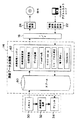
図1には、本実施形態に係る画像処理システム10が示されている。画像処理システム10は、写真フィルム(例えばネガフィルムやリバーサルフィルム)等の写真感光材料(以下単に写真フィルムと称する)に記録されているフィルム画像(被写体を撮影後、現像処理されることで可視化されたネガ画像又はポジ画像)を読み取って印画紙に記録することを高速で処理可能に構成されたデジタルラボシステム12に、画像データ交換機14及びインタフェース(I/F)回路16を介して入力装置群18及び出力装置群20が接続されて構成されている。
【0032】
入力装置群18は、画像データ交換機14に画像データを入力する各種の入力装置で構成されている。入力装置群18を構成する入力装置としては、例えばフロッピーディスク(FD)等の磁気ディスクやCD−R等の光ディスク、光磁気ディスク(MO)、デジタルスチルカメラ(DSC:以下、単に「デジタルカメラ」と称する)に装填可能なPCカードやICカード(以下、これらを「デジタルカメラカード」と総称する)等の各情報記憶媒体の何れかがセットされ、セットされた情報記憶媒体に記憶されている画像データを読み出して入力する情報記憶媒体読出装置22(図2参照)や、通信回線を介して接続された他の情報処理機器から送信された画像データを受信して入力する通信制御装置(図示省略)等を適用することができる。
【0033】
また出力装置群20は、画像データ交換機14から転送された出力用画像データに基づいて画像出力処理を行う各種の出力装置で構成されている。出力装置群20を構成する出力装置としては、例えば画像出力処理として情報記憶媒体(例えばCD−R)への画像データの書き込みを行う情報記憶媒体書込装置(例として、情報記憶媒体としてのCD−Rへの画像データの書き込みを行うCD−R書込装置24を図2に示す)、画像出力処理としてディスプレイ等の表示手段への画像の表示を行う画像表示装置、画像出力処理として通信回線を介して接続された他の情報処理機器への画像データの送信を行う通信制御装置等を適用することができる。
【0034】
ところで、入力装置群18を構成する各入力装置から入力される画像データのファイル構造は一定ではなく、互いに異なっていることが多い。このためI/F回路16は、入力装置から画像データが入力されると、入力された画像データのファイル構造を判断し、所定のファイル構造に変換して画像データ交換機14に入力する。また出力装置は、外部から転送される画像データのファイル構造を予め規定しているが、このファイル構造も出力装置群20を構成する各出力装置毎に異なっていることが多い。このためI/F回路16は、画像データ交換機14から出力装置へ画像データが転送される場合には、転送される画像データのファイル構造を転送先の出力装置に対応するファイル構造に変換する。
【0035】
デジタルラボシステム12は、スキャナ30、画像処理装置32及びプリンタ34が直列に接続されて構成されている。スキャナ30はエリアCCDセンサ等の読取センサを備えており、該読取センサにより写真フィルムに記録されているフィルム画像の読み取りを行う。フィルム画像の読み取りによって得られた画像データは画像処理装置32へ出力され、プリンタ34による画像出力処理(印画紙への画像の記録)に用いられるが、プリンタ34以外の出力装置による画像出力処理に用いることも指示された画像データについては画像交換機14へも出力される。
【0036】
画像処理装置32は、入力された画像データに対し、印画紙に適正な画質で画像を露光記録するための画像処理として、画素密度変換、色変換、画像の超低周波輝度成分の階調を圧縮するハイパートーン処理、粒状を抑制しながらシャープネスを強調するハイパーシャープネス処理、特殊画像処理(例えばLF(レンズ付きフィルム)によって撮影記録されたフィルム画像に対するLFのレンズの収差に起因する画質劣化の補正や赤目の補正等)等の各種の画像処理を行う各種の画像処理回路(図示省略)を備えている。画像処理装置32は各画像処理回路で行われる画像処理の処理条件を演算する。各画像処理回路は、画像データに対し、演算された処理条件に従って各種の画像処理を行い、画像処理後の画像データは記録用画像データとしてプリンタ34へ出力される。
【0037】
プリンタ34は、R,G,Bのレーザ光源と、該レーザ光源の作動を制御するレーザドライバを備えており(図示省略)、レーザ光源から射出されるR,G,Bのレーザ光を、入力された記録用画像データによって変調し、変調したレーザ光を印画紙上で走査させる。これにより、印画紙に画像が露光記録される。画像が露光記録された印画紙は、図示しないプロセッサ部へ送られて発色現像、漂白定着、水洗、乾燥の各処理が施され、印画紙に露光記録された画像が可視化される。なお、画像データ交換機14からプリンタ34に転送された画像データについても、上記と同様にレーザ光の変調、すなわち印画紙への画像の露光記録に用いられる。
【0038】
画像データ交換機14は、図1に示すように、CPU78、ROM42、RAM44、入出力ポート46A、46Bがバス48を介して互いに接続された構成を含んだパーソナルコンピュータやワークステーション等の情報処理装置と、大容量の情報記憶媒体(ハードディスク)を内蔵しバス48に接続されたハードディスク装置50と、装填されたCD−ROM52からプログラム等を読み出すCD−ROMドライバ54と、を備えている。入出力ポート46Aにはデジタルラボシステム12のスキャナ30及びプリンタ34が接続されており、入出力ポート46BにはI/F回路16を介して入力装置群18及び出力装置群20が接続されている。
【0039】
画像データ交換機14は、スキャナ30や入力装置群18の各入力装置から入力された画像データをハードディスク装置50の内蔵ハードディスクに一時記憶させる。従って、ハードディスク装置50の内蔵ハードディスクは、画像データ交換機14に入力された画像データを蓄積記憶するスプール60(図2参照)として機能する。また、画像データ交換機14は、入力された画像データに対し、スプール60に一時記憶する前に画像データの属性等を表すプロパティ情報を付加した後にスプール60に一時記憶させる。
【0040】
また、ハードディスク装置50の内蔵ハードディスクには、画像データに対して各種の画像処理を行うための各種の画像処理プログラムが記憶されており、画像データ交換機14のCPU40は、必要に応じて所定のタイミング(スプール60に画像データを一時記憶する前、及びスプール60に一時記憶した画像データを読み出した後の少なくとも一方のタイミング)でこれらのプログラムを選択的に実行し、画像データに対して各種の画像処理を行う。このように、画像データ交換機14は各種の画像処理を行う画像処理エンジン62(図2参照)としての機能も備えている。
【0041】
本実施形態では、画像データに対する画像処理として、図2にも示すように、画素密度(画素数)の異なる画像データに変換する「画素密度変換」、異なる色空間の画像データに変換する「色空間変換」、「データ圧縮(又は解凍)」、FlashPixと称する所定のフォーマット(互いに異なる複数種の解像度(画素密度)の画像データを含み、かつ各解像度の画像データが各々複数個の小領域(タイルと称する)に分割されたフォーマット)の画像データへの変換(又は逆変換)を行う「FlashPixフォーマット化」、デジタルカメラによる撮像によって得られた画像データ用の画質向上処理である「DSC set up 」、画像の鮮鋭度を向上させる「シャープネス補正」、画像データの不正複製等を防止するために所定の電子透かしデータを埋め込む「電子透かし」、複数種の画像データを合成して単一の画像の画像データ(例えば年賀状等を作成するための画像データ)を生成する「Composite 」等の各種の画像処理が用意されている。
【0042】
上記の各種画像処理のうち「DSC set up 」は、本発明に係る画像補正方法が適用された色補正・濃度補正処理(詳細は後述)と、画像の色彩を鮮やかにするための色変換処理と、から構成されている。色補正・濃度補正処理を画像データ交換機14のCPU40で実行させるための色補正・濃度補正プログラムは、その他の画像処理をCPU40で実行させるためのプログラムと共に、当初は、CD−ROM52に記憶されている。CD−ROM52がCD−ROMドライバ54に装填され、CD−ROM52から画像データ交換機14へのプログラムの移入(インストール)が指示されると、CD−ROMドライバ54によってCD−ROM52から色補正・濃度補正プログラムやその他のプログラムが読み出され、ハードディスク装置50の内蔵ハードディスクに記憶される。
【0043】
そして、色補正・濃度補正処理を実行すべきタイミングが到来すると、ハードディスク装置50の内蔵ハードディスクから色補正・濃度補正プログラムが読み出されてRAM44に記憶され(画像データ交換機14の電源投入時に各画像処理のプログラムを読み出してRAM44に記憶しておくようにしてもよい)、色補正・濃度補正プログラムが画像データ交換機14のCPU40によって実行される。これにより、画像データ交換機14は本発明に係る画像補正装置として機能する。なお、他の画像処理のプログラムについても上記と同様にして読み出されて実行される。
【0044】
このように、色補正・濃度補正プログラムやその他の画像処理のプログラムを記憶しているCD−ROM52及びハードディスク装置50の内蔵ハードディスクは本発明の記録媒体に対応している。
【0045】
次に本実施形態の作用として、画像データ交換機14に情報記憶媒体読出装置22(及びCD−R書込装置24)が接続されている態様(図2参照)を例に、情報記憶媒体読出装置22からデジタルラボシステム12のプリンタ34への画像データの転送について説明する。
【0046】
画像処理システム10では、ユーザが所有しているパーソナルコンピュータ等の情報処理装置で加工された画像データを記憶したFDやMOが持ち込まれてプリントの作成が依頼されたり、デジタルカメラによる撮像によって得られた画像データを記憶したデジタルカメラカードが持ち込まれてプリントの作成が依頼されたり、或いはスキャナ30から画像データ交換機14、CD−R書込装置24を経て転送された画像データが書き込まれたCD−Rが持ち込まれてプリントの作成(焼き増し)が依頼されることがある。
【0047】
この場合、ユーザから持ち込まれた情報記憶媒体が対応する情報記憶媒体読出装置22(FDドライブ、CDドライブ、MOドライブ、カードリーダ等の何れか)にセットされ、情報記憶媒体がセットされた情報記憶媒体読出装置22は、セットされた情報記憶媒体から処理対象の画像データを読み出した後に、読み出した画像データを、処理対象の画像データの各種の属性を表す属性情報、及び画像データの出力先がプリンタ34であることを表す情報と共に画像データ交換機14へ転送する。
【0048】
情報記憶媒体読出装置22から転送された画像データは、I/F回路16で所定のファイル構造に変換された後に画像データ交換機14に入力される。画像データ交換機14の画像処理エンジン62は、画像データの入力元が情報記憶媒体読出装置22であり、画像データと共に入力された画像データの出力先を表す情報から、入力された処理対象の画像データがプリンタ34へ出力すべき画像データであることを認識すると、処理対象の画像データがスプール60に記憶される前に、入力元(情報記憶媒体読出装置22の種類)に依存する処理対象の画像データの属性と出力先(プリンタ34)とに応じた最適な画像処理を行う。
【0049】
ここで、入力元の情報記憶媒体読出装置22がデジタルカメラカードからの画像データの読み出しを行う装置(カードリーダ)である場合には、画像処理エンジン92は、入力された画像データはデジタルカメラによる撮像によって生成されてデジタルカメラカードに記憶(この場合、データ圧縮されて記憶される)された画像データであると判断し、圧縮された画像データの解凍、印画紙への画像の記録に適した解像度(画素密度)の画像データへの変換、色補正・濃度補正処理を含む「DSC set up 」、画像の鮮鋭度を向上させる「シャープネス補正」等の画像処理を行う。
【0050】
以下、処理対象の画像データが、デジタルカメラカードから読み出された画像データである場合に、画像処理エンジン62(画像データ交換機14のCPU40)が色補正・濃度補正プログラムを実行することによって実施される色補正・濃度補正処理について、図3のフローチャートを参照して説明する。
【0051】
ステップ100では、変数nに0を代入すると共に、変数m,x,xi ,xj に各々1を代入する。ステップ102では、処理対象の画像データから画素位置xの画素のR,G,B各色の濃度を表す画素データr(x),g(x),b(x)を取り込む。ステップ104では、変数x(画素位置x)が「n×S0 +1」に等しいか否か判定する。なおS0 は定数であり、例えば「100」等の値が設定される。変数xは1に初期設定され、変数nは0に初期設定されているので、このときはステップ104の判定が肯定され、ステップ106へ移行する。
【0052】
ステップ106では、ステップ102で取り込んだ画素データr(x),g(x),b(x)を画像データサンプリング値rS ( xi ),gS ( xi ),bS ( xi )として保持(サンプリング)する。
rS ( xi )←r(x),gS ( xi )←g(x),bS ( xi )←b(x)
そして、ステップ108では変数xi ,nを1だけインクリメントする。
【0053】
ステップ110では、先のステップ102で取り込んだ画素データr(x),g(x),b(x)を、各色毎の被写体反射率を表す被写体反射率R(x),G(x),B(x)へ変換する。国際無線通信諮問委員会709勧告によれば、被写体反射率X(0〜1の値をとる)は、以下の関数F(X)によって8ビットのデジタル信号値(0〜255の値をとる)に割り付けることができる。
【0054】
【数1】

従って、画素データから被写体反射率への変換は、関数Fの逆変換(関数F−1による変換)を行うことで実現することができる(次式参照)。
R(x)←F−1(r(x)), G(x)←F−1(g(x)),B(x)←F−1(b(x))
【0056】
次のステップ112では、ステップ110で求めた被写体反射率R(x),G(x),B(x)を被写体反射率積算値R0 ,G0 ,B0 (初期値は0)に加算する。
R0 =R0 +R(x),G0 =G0 +G(x),B0 =B0 +B(x)
【0057】
ステップ114では、変数x(画素位置x)が「m×M0 」に等しいか否か判定する。なおM0 は定数であり、例えば「100」等の値が設定される。なお、定数M0 は定数S0 と同一の値であっても異なる値であってもよい。変数xは1に初期設定され、変数mは1に初期設定されているので、このときはステップ104の判定が否定され、ステップ122へ移行する。
【0058】
ステップ122では全ての画素データを取り込んだか否か判定する。判定が否定された場合には、変数xを1だけインクリメントしてステップ102に戻り、ステップ102では、画素データr(x),g(x),b(x)として、前回画素データを取り込んだ画素と隣接する画素のデータが取り込まれる。従って、このステップ122、124、102により、処理対象の画像データから、各画素のデータが画素位置xの昇順で順次取り込まれる。
【0059】
先に説明したステップ104〜108では、変数x(画素位置x)が「n×S0 +1」に等しい場合に、画素データを画像データサンプリング値としてサンプリングし、変数nの値を1だけインクリメントするので、図4(A)にも示すように、S0 個の画素のデータが順次取り込まれる間に、1個の画素のデータのみが画像データサンプリング値として選択的にサンプリングされる(S0 −1個の画素のデータが間引かれてサンプリングされる)ことになる。
【0060】
このように、画像データサンプリング値は本発明に係る第1の画像データに対応しており、ステップ104〜108は請求項6に記載の演算手段(より詳しくは、請求項3に記載の第1の画像データを求める演算手段)の一部を構成している。また、画像データサンプリング値としてデータがサンプリングされた画素に対応する原画像(デジタルカメラによる撮像によって得られた画像)上の微小面積の領域は、請求項4に記載の第1の小領域に対応している。
【0061】
一方、先に説明したステップ110、112では、取り込まれた画素データを被写体反射率に変換して順次積算しているが、変数x(画素位置x)が「m×M0 」に等しくなると(すなわちM0 個のデータを積算すると)ステップ114の判定が肯定され、ステップ116へ移行する。ステップ116では被写体反射率積算値R0 ,G0 ,B0 に基づき、次式に従って平均化サンプリング値ra ( xj ),ga ( xj ),ba ( xj )を演算する。
【0062】
【数2】
なお、Fは前述の関数F(x)を表す。
【0064】
そして、ステップ118では被写体反射率積算値R0 ,G0 ,B0 を0にし、ステップ120では変数xj ,mを各々1だけインクリメントしてステップ122へ移行する。従って、ステップ110〜120では、順次取り込まれるM0 個の画素のデータから被写体反射率を各々求め、その平均値(R0 /M0 、G0 /M0 、B0 /M0 )を8ビットのデジタル信号値に戻した値を平均化サンプリング値として設定しており、図4(B)にも示すように、M0 個の画素のデータを単位として、M0 個の画素のデータを平均化した値が平均化サンプリング値として設定される。
【0065】
このように、平均化サンプリング値は本発明に係る第2の画像データに対応しており、ステップ110〜120は請求項6に記載の演算手段(より詳しくは、請求項3に記載の第2の画像データを求める演算手段)の一部を構成している。また、1個の平均化サンプリング値の演算に用いられるM0 個の画素に対応する原画像(デジタルカメラによる撮像によって得られた画像)上の領域は、請求項4に記載の第2の小領域に対応している。
【0066】
ステップ122の判定が肯定されるとステップ126へ移行し、画像データサンプリング値rS ( xi ),gS ( xi ),bS ( xi )から、各チャンネル毎に画像データサンプリング値の平均値[r][g][b]を演算する(次式参照)。なお、次式において、Nは各チャンネル毎の画像データサンプリング値の総数を表す。画像データサンプリング値の平均値[r][g][b]は請求項4に記載の「第1の小領域を単位とする色度に関する平均値」に対応している。
【0067】
【数3】
ステップ128では平均化サンプリング値ra ( xj ),ga ( xj ),ba ( xj )に基づき、次式に従って平均輝度値[v]を演算する。なお、次式において、Mは各チャンネル毎の平均化サンプリング値の総数を表す。この平均輝度値[v]は請求項4に記載の「第2の小領域を単位とする輝度に関する平均値」に対応している。
【0069】
【数4】
そして、次のステップ130では、各チャンネル毎の画像データサンプリング値の平均値[r][g][b]及び平均輝度値[v]に基づいて、処理対象の画像データに対して色補正及び濃度補正を行う。この色補正及び濃度補正としては各種の補正方法があるが、例えば処理対象の画像データr,g,bに対し、次の(1)式の演算を行うことで、色補正及び濃度補正を行った画像データr’,g’,b’を得ることができる。
【0071】
【数5】
なお(1)式の右辺のうち、行列式はr,g,b各チャンネル毎の平均値を揃える色補正に相当し、平均輝度値[v]を含む係数項は平均輝度値を値「118 」に一致させる濃度補正に相当している。上記のステップ126〜130は請求項6に記載の補正手段に対応しており、ステップ130は、請求項4に記載の「色度に関する平均値に基づいて色補正を行い、輝度に関する平均値に基づいて濃度補正を行う」ことに対応している。
【0073】
画像データサンプリング値は、処理対象の画像データからS0 個の画素毎に1個の画素のデータをサンプリング(選択)して得られるデータであり、画像データサンプリング値としてデータがサンプリングされた画素に対応する原画像上の領域の面積が微小であるので、原画像中の面積が微小の高輝度点や低輝度点や、その他の原画像中の中性色であるべき箇所のデータを高い割合で含んでいる。上記では、この画像データサンプリング値の平均値[r][g][b]を用いて色補正を行っているので、色補正を常に高精度に行うことができ、類似のシーンを表す原画像の画像データに対しても、色バランスが略同一となるように補正することができる。
【0074】
また、平均化サンプリング値は、処理対象の画像データからM0 個の画素毎に平均値を演算して得られるデータであり、1個の平均化サンプリング値の演算に用いられるM0 個の画素に対応する原画像上の領域の面積が大きいので、原画像中の高輝度点や低輝度点の存在する箇所の輝度の変化が平均化され(すなわち原画像中の高周波成分が除去又は低減され)、中間的な濃度を表す値が平均化サンプリング値として設定される。上記では、平均化サンプリング値から求めた平均輝度値[v]を用いて濃度補正を行っているので、原画像中の高輝度点や低輝度点が濃度補正の精度及び安定性に悪影響を与えることが防止又は軽減され、濃度補正を常に高精度に行うことができると共に、類似のシーンを表す原画像の画像データに対しても、濃度が略同一となるように補正することができる。
【0075】
上述した色補正・濃度補正処理やその他の画像処理が終了すると、画像データ交換機14は、処理対象の画像データにプロパティ情報を付加してスプール60に一時記憶し、画像データの出力先であるプリンタ34に対し、プリンタ34に出力すべき画像データがスプール90に記憶されていることを通知する。そして、スプール90からの画像データの取り出しがプリンタ34より指示されると、画像データ交換機14は、処理対象の画像データをスプール90から取り出してプリンタ34へ転送する。
【0076】
プリンタ34は画像データ交換機14から転送された画像データを用いて印画紙70への画像の露光記録を行う。これにより、デジタルカメラカードから読み出された処理対象の画像データを用いてプリントが作成されることになる。なお、情報記憶媒体読出装置22から出力された画像データが、スプール90に一時記憶された後にプリンタ34に転送される迄の画像データの流れは、図2において、情報記憶媒体読出装置22からI/F回路16、画像処理エンジン92、スプール90を経てプリンタ34に至る一点鎖線の矢印に対応している。
【0077】
〔第2実施形態〕
次に本発明の第2実施形態について説明する。なお、第2実施形態は第1実施形態と同一の構成であるので、各部分に同一の符号を付して構成の説明を省略し、以下、本第2実施形態の作用について、第1実施形態と異なる部分についてのみ説明する。
【0078】
現在、市場に出回っている種々のデジタルカメラの中には、撮像(撮影)によって得られた高解像度の画像データ(元画像データという)に対し、画像上で近接した位置に存在する複数個の画素のデータの平均値を演算し、該平均値を前記複数個の画素を統合した画素の値とすることを画像全面に対して行うことで、元画像データを低解像度化したサムネイル画像と称される画像データ(サムネイル画像データ)を生成し、生成したサムネイル画像データを元画像データと共にデジタルカメラカードに書き込むものがある(「EXIF」規格に準拠しているデジタルカメラ)。
【0079】
例えば富士写真フイルム製のデジタルカメラ「Finepix700」では、被写体の撮像を行うと、撮像によって得られた1280画素×1024画素の元画像データから160画素×120画素のサムネイル画像データを生成し、元画像データ及びサムネイル画像データを各々デジタルカメラカードに書き込む構成となっている(図5参照)。なお、このサムネイル画像データは、例えばデジタルカメラカードに記憶されている元画像データが表す画像をディスプレイに一覧表示する等の場合に用いられる。
【0080】
本第2実施形態では、ユーザから持ち込まれた情報記憶媒体が、上記のような構成のデジタルカメラにより、元画像データと共にサムネイル画像データも書き込まれたデジタルカメラカードであった場合に、このデジタルカメラカードに記憶されているサムネイル画像データを本発明に係る第2の画像データとして用いて色補正及び濃度補正を行う。
【0081】
すなわち、ユーザから持ち込まれた情報記憶媒体が、元画像データ及びサムネイル画像データが書き込まれたデジタルカメラカードであった場合、情報記憶媒体読出装置22は、処理対象の画像データ(元画像データ)と共にサムネイル画像も読み出し、読み出した元画像データ及びサムネイル画像データを属性情報及び画像データの出力先(この場合はプリンタ34)を表す情報と共に画像データ交換機14へ転送する。
【0082】
そして画像データ交換機14の画像処理エンジン62では、入力元の情報記憶媒体読出装置22がデジタルカメラカードからの画像データの読み出しを行う装置(カードリーダ)であり、かつ通常の画像データ(元画像データ)と共にサムネイル画像データが入力された場合、図6に示す色補正・濃度補正処理を行う。以下、この色補正・濃度補正処理について説明する。
【0083】
ステップ200では、変数nに0を代入すると共に変数x,xi に各々1を代入する。ステップ202では、元画像データから画素位置xの画素のR,G,B各色の濃度を表す画素データr(x),g(x),b(x)を取り込み、ステップ204では、図3のステップ104と同様に、変数x(画素位置x)が「n×S0 +1」に等しいか否か判定する。判定が肯定された場合にはステップ206へ移行し、図3のステップ106と同様に、ステップ202で元画像データから取り込んだ画素データr(x),g(x),b(x)を画像データサンプリング値rS ( xi ),gS ( xi ),bS ( xi )として保持(サンプリング)する。そして、ステップ208では変数xi ,nを1だけインクリメントする。
【0084】
ステップ210では元画像データから全ての画素データを取り込んだか否か判定する。判定が否定された場合には、ステップ212で変数xを1だけインクリメントしてステップ202に戻り、ステップ202では、画素データr(x),g(x),b(x)として、前回画素データを取り込んだ画素と隣接する画素のデータが取り込まれる。
【0085】
従って、このステップ210、212、202により、元画像データから、各画素のデータが画素位置xの昇順で順次取り込まれ、ステップ204〜208により、図3の色補正・濃度補正処理と同様に、S0 個の画素のデータが順次取り込まれる間に、1個の画素のデータのみが画像データサンプリング値(本発明に係る第1の画像データ)として選択的にサンプリングされる(S0 −1個の画素のデータが間引かれてサンプリングされる)。
【0086】
画像データサンプリング値は図5に示されているサンプリング画像データに対応しており、例えば元画像データが、富士写真フイルム製のデジタルカメラ「Finepix700」による撮像によって得られた1280画素×1024画素の画像データであったとすると、上記処理により、例えば128画素×102画素のサンプリング画像データが得られることになる。
【0087】
ステップ210の判定が肯定されるとステップ214へ移行し、図4のステップ126と同様に、画像データサンプリング値rS ( xi ),gS ( xi ),bS ( xi )から、各チャンネル毎に画像データサンプリング値の平均値[r][g][b]を演算する(図5も参照)。
【0088】
ステップ216ではサムネイル画像データを取り込み、サムネイル画像データの各画素の値r(x),g(x),b(x)に基づき、次式に従って平均輝度値[v]を演算する(図5も参照)。なお、次式におけるMはサムネイル画像データの画素数を表す。また、ステップ216の処理のうちサムネイル画像データを取り込む処理は、先のステップ202と共に、第1の画像データ及び第2の画像データを取得する取得手段を構成している。
【0089】
【数6】
前述のように、サムネイル画像データは、元画像データに対し、画像上で近接した位置に存在する複数個の画素のデータの平均値を演算し、該平均値を前記複数個の画素を統合した画素の値とすることを画像全面に対して行うことで生成された画像データであり、本発明に係る第2の画像データに対応している。
【0091】
従って、デジタルカメラにおけるサムネイル画像データの生成は、請求項2に記載の「カラー原画像から、該カラー原画像の高周波成分が除去又は低減された第2の画像データを求め」ること(詳しくは請求項3に記載の「原画像データ(元画像データ)から所定数の画素毎に平均値を演算することで第2の画像データを求める」こと)に対応していると共に、請求項4に記載の「カラー原画像上の各箇所における、第1の小領域よりも面積が大きい第2の小領域を単位とする」R,G,B各色の濃度を求めることに対応している。
【0092】
そして次のステップ218では、各チャンネル毎の画像データサンプリング値の平均値[r][g][b]及び平均輝度値[v]に基づいて、図3のステップ130と同様に、処理対象の画像データに対して色補正及び濃度補正を行う。このように、ステップ214、ステップ216の処理のうち平均輝度値[v]を演算する処理、及びステップ218は請求項5に記載の補正手段に対応している。
【0093】
上記で説明した色補正・濃度補正処理では、画像データサンプリング値の平均値[r][g][b]を用いて色補正を行っているので、図3の色補正・濃度補正処理と同様に色補正を常に高精度に行うことができ、類似のシーンを表す原画像の画像データに対しても、色バランスが略同一となるように補正することができる。
【0094】
また、サムネイル画像データは、処理対象の画像データから複数個の画素毎に平均値を演算して得られるデータであり、サムネイル画像データの1画素に対応する原画像上の領域の面積が大きいので、原画像中の高輝度点や低輝度点の存在する箇所の輝度の変化が平均化され(すなわち原画像中の高周波成分が除去又は低減され)、サムネイル画像データの各画素の値として中間的な濃度を表す値が設定される。
【0095】
上記で説明した色補正・濃度補正処理では、サムネイル画像データから求めた平均輝度値[v]を用いて濃度補正を行っているので、原画像中の高輝度点や低輝度点が濃度補正の精度及び安定性に悪影響を与えることが防止又は軽減され、図3の濃度補正・色補正処理と同様に濃度補正を常に高精度に行うことができると共に、類似のシーンを表す原画像の画像データに対しても、濃度が略同一となるように補正することができる。
【0096】
なお、上記では本発明に係る記録媒体として、CD−ROM52及びハードディスク装置50の内蔵ハードディスクを例に説明したが、本発明はこれに限定されるものではなく、例えばフロッピーディスク等の磁気ディスク、CD−R等の光ディスク、MO等の光磁気ディスク、メモリカード、ICカード等の各種の情報記憶媒体を、本発明に係る記録媒体として適用可能であることは言うまでもない。
【0097】
また、上記では処理対象の画像データからM0 個の画素毎に平均値を演算することで、原画像中の高周波成分が除去又は低減された第2の画像データ(平均化サンプリング値)を得ていたが、これに代えて処理対象の画像データに高周波成分を除去又は減衰させるフィルタをかけることで、本発明に係る第2の画像データを得るようにしてもよい。
【0098】
また、上記では画像データ交換機14のCPU40が色補正・濃度補正プログラムを実行することによって色補正・濃度補正処理を行うようにしていたが、これに限定されるものではなく、色補正・濃度補正処理を行う専用のハードウェア(画像処理回路)を設け、該画像処理回路で色補正・濃度補正処理を行うようにしてもよい。
【0099】
更に、上記ではデジタルカメラによる撮像によって生成されたデジタルの画像データを処理対象としていたが、本発明の処理対象はアナログの画像信号であってもよく、例えばアナログのビデオカメラ等のようにアナログの画像信号を処理する機器における色補正や濃度補正に本発明を適用することも可能である。また上記では色補正及び濃度補正を各々行っていたが、何れか一方のみを行ってもよいことは言うまでもない。
【0100】
以上、本発明の実施形態について説明したが、上記の実施形態は、特許請求の範囲に記載した事項の実施態様以外に、以下に記載した事項の実施態様を含んでいる。
【0101】
(1)カラー原画像上の各箇所における、微小面積の第1の小領域を単位とする色度に関する平均値を求める第1の演算手段と、前記カラー原画像上の各箇所における、前記第1の小領域よりも面積が大きい第2の小領域を単位とする輝度に関する平均値を求める第2の演算手段と、前記第1の演算手段によって演算された色度に関する平均値に基づいて前記カラー原画像に対する色補正を行い、かつ前記第2の演算手段によって演算された輝度に関する平均値に基づいて前記カラー原画像に対する濃度補正を行う補正手段と、を含む画像補正装置。
【0102】
(2)カラー原画像上の各箇所における、微小面積の第1の小領域を単位とする色度に関する平均値を求めると共に、前記カラー原画像上の各箇所における、前記第1の小領域よりも面積が大きい第2の小領域を単位とする輝度に関する平均値を求める第1のステップ、前記色度に関する平均値に基づいて前記カラー原画像に対する色補正を行い、かつ前記輝度に関する平均値に基づいて前記カラー原画像に対する濃度補正を行う第2のステップを含む処理をコンピュータに実行させるためのプログラムが記録された記録媒体。
【0103】
【発明の効果】
以上説明したように請求項1及び請求項5記載の発明は、カラー原画像を表す第1の画像データを用いてカラー原画像に対する色補正を行うと共に、カラー原画像を表しかつ第1の画像データよりもカラー原画像の高周波成分が除去又は低減された第2の画像データを用いてカラー原画像に対する濃度補正を行うので、色補正及び濃度補正を常に高い精度で行うことができる、という優れた効果を有する。
【0104】
請求項2記載の発明及び請求項6記載の発明は、カラー原画像を表す第1の画像データ、及びカラー原画像を表しかつ第1の画像データよりもカラー原画像の高周波成分が除去又は低減された第2の画像データを求め、第1の画像データを用いてカラー原画像に対する色補正を行うと共に、第2の画像データを用いてカラー原画像に対する濃度補正を行うので、色補正及び濃度補正を常に高い精度で行うことができる、という優れた効果を有する。
【0105】
請求項3記載の発明は、請求項2の発明において、原画像データから所定数の画素毎に1個の画素のデータを選択することで第1の画像データを求め、原画像データから所定数の画素毎に平均値を演算することで第2の画像データを求めるので、上記効果に加え、原画像データに含まれるカラー原画像の高周波成分を損うことなく、第1の画像データのデータ量を小さくすることができると共に、複雑な処理を行うことなく高周波成分を除去又は低減した第2の画像データを得ることができる、という効果を有する。
【0106】
請求項4記載の発明は、カラー原画像上の各箇所における、微小面積の第1の小領域を単位とする色度に関する平均値に基づいてカラー原画像に対する色補正を行い、カラー原画像上の各箇所における、第1の小領域よりも面積が大きい第2の小領域を単位とする輝度に関する平均値に基づいてカラー原画像に対する濃度補正を行うので、色補正及び濃度補正を常に高い精度で行うことができる、という優れた効果を有する。
【0107】
請求項7記載の発明は、カラー原画像を表す第1の画像データを用いてカラー原画像に対する色補正を行うと共に、カラー原画像を表しかつ第1の画像データよりもカラー原画像の高周波成分が除去又は低減された第2の画像データを用いてカラー原画像に対する濃度補正を行うステップを含む処理をコンピュータに実行させるためのプログラムを記録媒体に記録したので、色補正及び濃度補正を常に高い精度で行うことができる、という優れた効果を有する。
【0108】
請求項8記載の発明は、カラー原画像から、該カラー原画像を表す第1の画像データ、及びカラー原画像を表しかつ第1の画像データよりもカラー原画像の高周波成分が除去又は低減された第2の画像データを求める第1のステップ、第1の画像データを用いてカラー原画像に対する色補正を行うと共に、第2の画像データを用いてカラー原画像に対する濃度補正を行う第2のステップを含む処理をコンピュータに実行させるためのプログラムを記録媒体に記録したので、色補正及び濃度補正を常に高い精度で行うことができる、という優れた効果を有する。
【図面の簡単な説明】
【図1】本実施形態に係る画像処理システムの概略構成を示すブロック図である。
【図2】図1の画像処理システムにおいて、入力装置として情報記憶媒体読出装置が、出力装置としてCD−R書込装置が接続されている場合の画像データに対する処理の流れを示す概念図である。
【図3】第1実施形態に係る色補正・濃度補正処理の内容を示すフローチャートである。
【図4】(A)は色補正のための画像データのサンプリング、(B)は濃度補正のための平均化サンプリング値の演算を各々示す概念図である。
【図5】第2実施形態に係る色補正・濃度補正処理におけるデータの流れを示すイメージ図である。
【図6】第2実施形態に係る色補正・濃度補正処理の内容を示すフローチャートである。
【符号の説明】
10 画像処理システム
14 画像データ交換機
22 情報記憶媒体読出装置
40 CPU
50 ハードディスク装置
52 CD−ROM
54 CD−ROMドライバ[0001]
TECHNICAL FIELD OF THE INVENTION
The present invention relates to an image correction method, an image correction device, and a recording medium, and more particularly, to an image correction method for correcting the density and color of an image, an image correction device to which the image correction method can be applied, and a computer that executes the image correction method. The present invention relates to a recording medium on which a program to be executed is recorded.
[0002]
[Prior art]
It is necessary to perform color correction such as white balance adjustment and density correction for optimizing the density of the entire image on analog image signals and image data obtained by imaging with a video camera or shooting with a digital still camera. In general, color correction and density correction of an image are performed by sampling an image signal or image data for each of a plurality of channels (for example, R, G, and B) and averaging each channel based on data of each channel obtained by sampling. Based on the calculated average value, the average value relating to chromaticity is neutral (gray) for color correction and the average value relating to luminance is intermediate value (for reflection density). In this case, the correction value of the color correction and the correction value of the density correction are calculated so that the image data is expressed as “0.75”, and the density of each pixel is expressed as 8 bits. Signals and image data are adjusted (converted).
[0003]
In this specification, in addition to simple averaging, the entire screen is divided into a plurality of regions, such as divided photometry or evaluation photometry, and an average value is calculated for each region, and the average value for each region is calculated for each region. The term “average value” includes various evaluation values similar to the average value, such as values obtained by a method of combining using different weighting factors for each.
[0004]
[Problems to be solved by the invention]
In color correction and density correction of images, improvement in correction accuracy is required, and operation stability such as correction of an image representing a similar scene with an approximate correction value or a low malfunction rate is possible. There is also a demand for improvement. In order to improve the stability of operation and stabilize the correction results by color correction and density correction for images representing similar scenes, it is necessary to stabilize the average value used for calculating the correction values for color correction and density correction. .
[0005]
For this reason, conventionally, the average value has been stabilized solely by devising an algorithm for obtaining the average value (for example, see Japanese Patent Application Laid-Open No. 3-160891). However, it is not easy to simultaneously improve the correction accuracy and the operation stability for each of the color correction and the density correction, and there is a problem that the accuracy of the color correction and the density correction varies from image to image.
[0006]
The present invention has been made in consideration of the above-described facts, and has as its object to provide an image correction method, an image correction apparatus, and a recording medium that can always perform color correction and density correction with high accuracy.
[0007]
[Means for Solving the Problems]
Desirable color correction of the image is a correction to make a portion of the original image that should be a neutral color a neutral color, and should be the neutral color included in the data for obtaining the correction value of the color correction As the ratio of the data at the location increases, the accuracy of the color correction based on the obtained correction value improves. Most of the high luminance points or low luminance points in the original image should be neutral colors, but the high luminance points or low luminance points in the original image often have a small area on the original image. Therefore, the portion where the high luminance point and the low luminance point exist on the original image contains the high frequency component of the spatial frequency. On the other hand, since the density correction of an image is a correction for setting an average value relating to the luminance of the original image to an intermediate value, data for calculating a correction value of the density correction includes data of a high luminance point or a low luminance point in the original image. Is included, the average value relating to the luminance of the original image is likely to fluctuate, leading to a decrease in the accuracy and stability of density correction.
[0008]
Based on the above, the image correction method according to the first aspect of the present invention provides a color original image Represents First image data Color correction coefficient is derived from While performing color correction on the color original image using High frequency components of the color original image representing the color original image and being removed or reduced from the first image data. Second image data Derive the density correction coefficient from To perform density correction on the color original image.
[0009]
According to the first aspect of the present invention, a color original image Represents First image data Color correction coefficient is derived from Is used to perform color correction on the color original image. Since the first image data contains high-frequency components of a color image, data of a high-luminance point or a low-luminance point having a small area in the color original image is also stored. Many data are included. Therefore, color correction can be performed with high accuracy.
[0010]
In the invention of
[0011]
By the way, a device that generates image data (for example, a digital still camera that generates image data by capturing an image of a subject, a scanner that generates image data by reading an image recorded on a recording medium such as a photographic film, etc.) Among them, there is a configuration that generates image data corresponding to the first image data of the present invention and image data corresponding to the second image data of the present invention. Further, for example, when image data corresponding to the first image data of the present invention is also input into a device (for example, various image processing devices, interface circuits, and the like) that processes and outputs input image data. There is a configuration in which image data corresponding to the second image data of the present invention is generated and each image data is output. In the first aspect of the present invention, the first image data and the second image data may be, for example, data generated by the above-described apparatus, or may be obtained from a color original image as described below. Is also good.
[0012]
That is, in the image correction method according to the second aspect of the present invention, the color original image is converted from the color original image. Represents First image data, and High frequency components of the color original image representing the color original image and being removed or reduced from the first image data. Obtaining second image data, the first image data Color correction coefficient is derived from And color correction for the color original image using the second image data Derive the density correction coefficient from To perform density correction on the color original image.
[0013]
According to the second aspect of the present invention, the color original image , Color original image Represents First image data is obtained, and the first image data Color correction coefficient is derived from Is used to perform color correction on the color original image. As described above, since the first image data includes the high-frequency components of the color image, the data of the high-luminance point and the low-luminance point having a small area in the color original image are also stored, and the neutral color is used. It contains a lot of data where it should be. Therefore, similar to the first aspect of the invention, color correction can be performed with high accuracy.
[0014]
According to the second aspect of the present invention, the color original image , Color original image And the high frequency component of the color original image has been removed or reduced compared to the first image data. The second image data is obtained, and the second image data Derive the density correction coefficient from Is used to perform density correction on the color original image. As described above, since the high frequency components of the color original image are removed or reduced in the second image data, high luminance points and low luminance points in the color original image exist on the second image data. Since the change in luminance at the portion is slowed down (averaged), it is possible to prevent or reduce that a high luminance point or a low luminance point in the color original image adversely affects the accuracy and stability of the density correction. . Therefore, according to the second aspect of the invention, the color correction and the density correction can always be performed with high accuracy, as in the first aspect of the invention.
[0015]
By the way, when the original image data representing the color original image already exists, for example, the original image data is used as it is as the first image data, and the second image data is obtained by removing high-frequency components from the original image data. Alternatively, it can be obtained by applying a filter for reduction. However, as described in claim 3, by selecting data of one pixel for every predetermined number of pixels from the original image data representing the color original image, It is preferable that the first image data is obtained and the second image data is obtained by calculating an average value for each of a predetermined number of pixels from the original image data.
[0016]
According to the third aspect of the present invention, since the first image data is obtained by selecting data of one pixel for every predetermined number of pixels from the original image data, the color original image included in the original image data is obtained. The data amount of the first image data can be reduced without damaging the high frequency components. In addition, since the second image data is obtained by calculating an average value for each of a predetermined number of pixels from the original image data, the second image processing apparatus eliminates or reduces high-frequency components without performing complicated processing such as filtering. Image data can be obtained.
[0017]
According to the third aspect of the present invention, instead of selecting data of one pixel for each predetermined number of pixels, a plurality of data (a high-frequency component in a color original image is not greatly attenuated) may be selected for each predetermined number of pixels. (Preferably the number of pixels) may be selected to obtain the first image data by calculating the average value.
[0018]
In the image correction method according to the fourth aspect of the present invention, an average value regarding chromaticity in units of a first small region having a small area at each location on the color original image is obtained, and each of the average values on the color original image is obtained. An average value for luminance in units of a second small region having an area larger than the first small region is determined, and color correction is performed on the color original image based on the average value for the chromaticity; and Density correction is performed on the color original image based on the average value regarding the luminance.
[0019]
Since the first small area has a small area, the value of the chromaticity in units of the first small area at each location on the color original image includes the high luminance point or the low luminance point existing in the color original image. The value representing the chromaticity of the luminance point will be included in a high ratio, and the average value of the chromaticity in units of the first small area will be the color of the high luminance point or the low luminance point existing in the color original image. Degree, that is, a value strongly reflecting the chromaticity of a portion that should be a neutral color. According to the fourth aspect of the present invention, the color correction is performed on the color original image based on the average value of the chromaticity in units of the first small area having a small area at each location on the color original image. It can be performed with high accuracy.
[0020]
Further, since the second small area has a larger area than the first small area, even if a high luminance point or a low luminance point exists in the second small area, the second small area is defined as a unit. The value regarding the luminance to be obtained is a value close to the average value regarding the luminance of the original image by averaging the luminance of each portion in the second small area. According to the fourth aspect of the invention, in each portion on the color original image, an average value regarding the luminance in units of the second small area is obtained, and the density correction for the color original image is performed based on the average value regarding the luminance. It is possible to prevent or reduce the adverse effect of the high luminance point and the low luminance point in the color original image on the accuracy and stability of the density correction, and it is possible to perform the density correction with high accuracy. Therefore, according to the fourth aspect of the invention, the color correction and the density correction can always be performed with high accuracy, as in the second aspect of the invention.
[0021]
An image correction apparatus according to a fifth aspect of the present invention provides a color original image. Represents First image data Color correction coefficient is derived from While performing color correction on the color original image using High frequency components of the color original image representing the color original image and being removed or reduced from the first image data. Second image data Derive the density correction coefficient from And a correction means for performing density correction on the color original image using
[0022]
According to the fifth aspect of the present invention, the color original image is corrected by the correction means. Represents First image data From the color correction coefficient, and the derived color correction coefficient Color correction is performed on the color original image using And the high frequency component of the color original image has been removed or reduced compared to the first image data. Second image data A density correction coefficient is derived from the density correction coefficient. Is used to perform the density correction on the color original image, so that the color correction and the density correction can always be performed with high accuracy, as in the first aspect of the present invention.
[0023]
In the invention of claim 5, the first image data used by the correction means for color correction and the second image data used for density correction are, for example, first image data containing a high-frequency component of a color original image, It may be obtained by providing an obtaining means for obtaining the second image data from which the components have been removed or reduced (for example, from the above-described image data generating apparatus), or as described below. It may be obtained from the original image.
[0024]
That is, the image correcting apparatus according to the invention of claim 6 converts the color original image into the color original image. Represents First image data, and High frequency components of the color original image representing the color original image and being removed or reduced from the first image data. Calculating means for obtaining second image data; and the first image data Color correction coefficient is derived from And color correction for the color original image using the second image data Derive the density correction coefficient from And a correcting unit for performing density correction on the color original image using the color image.
[0025]
According to the sixth aspect of the present invention, a color original image Represents First image data and color original image And the high frequency component of the color original image has been removed or reduced compared to the first image data. The second image data is obtained from the color original image by the calculating means, and the correcting means outputs the first image data Color correction coefficient is derived from And color correction for the color original image using the second image data. Derive the density correction coefficient from Is used to perform the density correction on the color original image, so that the color correction and the density correction can always be performed with high accuracy, as in the second aspect of the present invention.
[0026]
The recording medium according to the present invention is a color original image. Represents First image data Color correction coefficient is derived from While performing color correction on the color original image using High frequency components of the color original image representing the color original image and being removed or reduced from the first image data. Second image data Derive the density correction coefficient from And a program for causing a computer to execute a process including a step of performing density correction on the color original image using the program.
[0027]
The recording medium according to the seventh aspect of the present invention stores a program for causing a computer to execute the processing including the above steps, that is, the processing according to the image correction method according to the first aspect of the present invention. By reading and executing the program recorded on the recording medium, the color correction and the density correction can always be performed with high accuracy, as in the first aspect of the present invention.
[0028]
The recording medium according to the invention according to claim 8, wherein the color original image is converted from the color original image. Represents First image data, and High frequency components of the color original image representing the color original image and being removed or reduced from the first image data. A first step of obtaining second image data, the first image data Color correction coefficient is derived from And color correction for the color original image using the second image data Derive the density correction coefficient from A program for causing a computer to execute a process including a second step of performing density correction on the color original image using the program is recorded.
[0029]
A program for causing a computer to execute the processing including the first step and the second step, that is, the processing according to the image correction method according to the second aspect of the present invention, in the recording medium according to the eighth aspect of the present invention. Is recorded, the computer reads and executes the program recorded on the recording medium, so that the color correction and the density correction can always be performed with high accuracy, as in the second aspect of the present invention.
[0030]
BEST MODE FOR CARRYING OUT THE INVENTION
Hereinafter, an example of an embodiment of the present invention will be described in detail with reference to the drawings.
[0031]
[First Embodiment]
FIG. 1 shows an
[0032]
The
[0033]
The
[0034]
By the way, the file structure of the image data input from each of the input devices constituting the
[0035]
The
[0036]
The
[0037]
The
[0038]
As shown in FIG. 1, the
[0039]
The
[0040]
Various image processing programs for performing various types of image processing on image data are stored in a built-in hard disk of the
[0041]
In the present embodiment, as the image processing for the image data, as shown in FIG. 2, “pixel density conversion” for converting to image data having different pixel densities (the number of pixels) and “color for converting to image data of different color spaces” A predetermined format called “spatial conversion”, “data compression (or decompression)”, or FlashPix (including image data of a plurality of different resolutions (pixel densities), and each of the image data of each resolution has a plurality of small areas ( "FlashPix format" for converting (or inversely converting) image data of a format divided into tiles), and "DSC set up" for improving the image quality of image data obtained by imaging with a digital camera. "Sharpness correction" to improve the sharpness of the image, and predetermined power to prevent unauthorized duplication of image data. Various image processing such as “digital watermark” for embedding watermark data and “Composite” for combining multiple types of image data to generate image data of a single image (for example, image data for creating a New Year's card etc.) are available. It is prepared.
[0042]
Among the above various image processes, “DSC set up” includes a color correction / density correction process (to be described in detail later) to which the image correction method according to the present invention is applied, and a color conversion process for making the colors of an image vivid. And is composed of The color correction / density correction program for causing the
[0043]
Then, when it is time to execute the color correction / density correction processing, the color correction / density correction program is read from the internal hard disk of the
[0044]
As described above, the CD-
[0045]
Next, as an operation of the present embodiment, the information storage medium reading device 22 (and the CD-R writing device 24) is connected to the image data exchange 14 (see FIG. 2) as an example. The transfer of image data from 22 to the
[0046]
In the
[0047]
In this case, the information storage medium brought in from the user is set in the corresponding information storage medium reading device 22 (any one of an FD drive, a CD drive, an MO drive, a card reader, etc.), and the information storage medium in which the information storage medium is set is set. After reading the image data to be processed from the set information storage medium, the
[0048]
The image data transferred from the information storage
[0049]
Here, when the input information storage
[0050]
Hereinafter, when the image data to be processed is the image data read from the digital camera card, the image processing engine 62 (the
[0051]
In
[0052]
In
r S (X i ) ← r (x), g S (X i ) ← g (x), b S (X i ) ← b (x)
Then, in
[0053]
In step 110, the pixel data r (x), g (x), b (x) fetched in
[0054]
(Equation 1)
Therefore, the conversion from the pixel data to the object reflectance is the inverse of the function F (function F -1 ) (See the following equation).
R (x) ← F -1 (R (x)), G (x) ← F -1 (G (x)), B (x) ← F -1 (B (x))
[0056]
In the
R0 = R 0 + R (x), G 0 = G 0 + G (x), B 0 = B 0 + B (x)
[0057]
In
[0058]
In
[0059]
In steps 104 to 108 described above, the variable x (pixel position x) is set to “n × S 0 +1 ", the pixel data is sampled as an image data sampling value, and the value of the variable n is incremented by one. Therefore, as shown in FIG. 0 While the data of the pixels are sequentially taken in, only the data of one pixel is selectively sampled as the image data sampling value (S 0 -1 pixel data is thinned out and sampled).
[0060]
As described above, the image data sampling value corresponds to the first image data according to the present invention, and steps 104 to 108 are performed by the arithmetic means according to claim 6 (more specifically, the first means according to claim 3). (A calculating means for obtaining the image data). Further, an area having a small area on an original image (an image obtained by imaging with a digital camera) corresponding to a pixel whose data is sampled as an image data sampling value corresponds to the first small area according to claim 4. are doing.
[0061]
On the other hand, in
[0062]
(Equation 2)
Note that F represents the above-described function F (x).
[0064]
Then, in step 118, the subject reflectance integrated value R 0 , G 0 , B 0 Is set to 0, and in
[0065]
As described above, the averaged sampling value corresponds to the second image data according to the present invention, and the steps 110 to 120 are performed by the calculation means according to claim 6 (more specifically, the second means according to claim 3). (A calculating means for obtaining the image data). Also, M used to calculate one averaged sampling value 0 The region on the original image (the image obtained by imaging with the digital camera) corresponding to the pixels corresponds to the second small region according to claim 4.
[0066]
If the determination in
[0067]
(Equation 3)
In
[0069]
(Equation 4)
Then, in the next step 130, based on the average value [r] [g] [b] and the average luminance value [v] of the image data sampling values for each channel, color correction and Perform density correction. There are various correction methods for the color correction and the density correction. For example, the color correction and the density correction are performed by performing the calculation of the following equation (1) on the image data r, g, and b to be processed. Image data r ', g', b 'can be obtained.
[0071]
(Equation 5)
In the right-hand side of the equation (1), the determinant corresponds to color correction for equalizing the average value of each of the channels r, g, and b, and the coefficient term including the average luminance value [v] represents the average luminance value of "118". Is equivalent to density correction. The above steps 126 to 130 correspond to the correcting means described in claim 6, and step 130 performs “the color correction is performed based on the average value related to chromaticity, and the average value related to luminance is calculated. Perform density correction on the basis of "."
[0073]
The image data sampling value is S from the image data to be processed. 0 Data obtained by sampling (selecting) the data of one pixel for each pixel. Since the area of the region on the original image corresponding to the pixel from which the data is sampled is small as the image data sampling value, In addition, a high proportion of high luminance points and low luminance points having a small area in the original image and other data that should be neutral in the original image are included. In the above description, since the color correction is performed using the average value [r] [g] [b] of the image data sampling values, the color correction can always be performed with high accuracy, and the original image representing a similar scene can be obtained. Can be corrected so that the color balance is substantially the same.
[0074]
Also, the averaged sampling value is M from the image data to be processed. 0 Data obtained by calculating an average value for each pixel, and M is used for calculating one averaged sampling value. 0 Since the area of the region on the original image corresponding to the number of pixels is large, the change in the luminance at the position where the high luminance point or the low luminance point exists in the original image is averaged (that is, the high frequency component in the original image is removed). Or a value representing an intermediate density is set as an averaged sampling value. In the above, since the density correction is performed using the average luminance value [v] obtained from the averaged sampling value, the high luminance point and the low luminance point in the original image adversely affect the accuracy and stability of the density correction. This can prevent or reduce such a situation, and the density correction can always be performed with high accuracy, and the image data of the original image representing a similar scene can be corrected so that the density is substantially the same.
[0075]
When the above-described color correction / density correction processing and other image processing are completed, the
[0076]
The
[0077]
[Second embodiment]
Next, a second embodiment of the present invention will be described. Since the second embodiment has the same configuration as the first embodiment, the same reference numerals are given to the respective portions, and the description of the configuration is omitted. Hereinafter, the operation of the second embodiment will be described in the first embodiment. Only parts different from the embodiment will be described.
[0078]
At present, among various digital cameras on the market, a plurality of digital cameras existing at positions close to each other with respect to high-resolution image data (original image data) obtained by imaging (photographing). By calculating the average value of the pixel data and making the average value the pixel value obtained by integrating the plurality of pixels over the entire image, the original image data is referred to as a reduced-resolution thumbnail image. Some image data (thumbnail image data) are generated and the generated thumbnail image data is written to a digital camera card together with the original image data (a digital camera conforming to the “EXIF” standard).
[0079]
For example, in a digital camera “Finepix 700” manufactured by Fuji Photo Film, when a subject is imaged, thumbnail image data of 160 × 120 pixels is generated from original image data of 1280 × 1024 pixels obtained by the imaging, and the original image is generated. Data and thumbnail image data are written into a digital camera card (see FIG. 5). Note that this thumbnail image data is used, for example, when a list of images represented by original image data stored in a digital camera card is displayed on a display.
[0080]
In the second embodiment, when the information storage medium brought in by the user is a digital camera card in which thumbnail image data is written together with original image data by the digital camera having the above configuration, Color correction and density correction are performed using the thumbnail image data stored on the card as the second image data according to the present invention.
[0081]
That is, when the information storage medium brought in by the user is a digital camera card in which the original image data and the thumbnail image data are written, the information storage
[0082]
In the
[0083]
In
[0084]
In
[0085]
Therefore, in
[0086]
The image data sampling value corresponds to the sampled image data shown in FIG. 5. For example, the original image data is an image of 1280 pixels × 1024 pixels obtained by imaging with a digital camera “Finepix 700” manufactured by Fuji Photo Film. If the data is data, sampling image data of, for example, 128 pixels × 102 pixels is obtained by the above processing.
[0087]
If the determination in
[0088]
In
[0089]
(Equation 6)
As described above, the thumbnail image data is obtained by calculating the average value of the data of a plurality of pixels existing at positions close to each other on the image with respect to the original image data, and integrating the average value with the plurality of pixels. This is image data generated by performing pixel values on the entire image, and corresponds to the second image data according to the present invention.
[0091]
Therefore, the generation of the thumbnail image data in the digital camera is to obtain the second image data from which the high-frequency components of the color original image have been removed or reduced from the color original image according to claim 2 (in detail, Claim 3 corresponds to "determining the second image data by calculating an average value for each of a predetermined number of pixels from the original image data (original image data)". This corresponds to the determination of the density of each of the R, G, and B colors described above, "in each location on the color original image, a unit is a second small area having an area larger than the first small area."
[0092]
Then, in the next step 218, based on the average value [r] [g] [b] and the average luminance value [v] of the image data sampling values for each channel, as in step 130 in FIG. Color correction and density correction are performed on the image data. As described above, the processing of calculating the average luminance value [v] of the processing of
[0093]
In the above-described color correction / density correction processing, since the color correction is performed using the average value [r] [g] [b] of the image data sampling values, it is the same as the color correction / density correction processing in FIG. Color correction can always be performed with high precision, and correction can be performed so that the color balance is substantially the same even for image data of an original image representing a similar scene.
[0094]
The thumbnail image data is data obtained by calculating an average value for each of a plurality of pixels from the image data to be processed, and the area of the region on the original image corresponding to one pixel of the thumbnail image data is large. In other words, the change in luminance at a portion where a high luminance point or a low luminance point exists in the original image is averaged (that is, high frequency components in the original image are removed or reduced), and an intermediate value is obtained as a value of each pixel of the thumbnail image data. Is set.
[0095]
In the color correction / density correction processing described above, since the density correction is performed using the average luminance value [v] obtained from the thumbnail image data, the high luminance points and the low luminance points in the original image are subjected to the density correction. A negative effect on accuracy and stability is prevented or reduced, and the density correction can always be performed with high accuracy as in the density correction / color correction processing in FIG. 3 and image data of an original image representing a similar scene. Can be corrected so that the densities are substantially the same.
[0096]
Although the recording medium according to the present invention has been described above by taking the CD-
[0097]
Also, in the above description, M 0 By calculating the average value for each pixel, the second image data (averaged sampling value) from which the high-frequency component in the original image has been removed or reduced has been obtained. The second image data according to the present invention may be obtained by applying a filter for removing or attenuating high frequency components to the data.
[0098]
In the above description, the color correction / density correction processing is performed by the
[0099]
Furthermore, in the above description, digital image data generated by imaging with a digital camera is processed. However, the processing target of the present invention may be an analog image signal, for example, an analog video camera or the like. The present invention can also be applied to color correction and density correction in a device that processes an image signal. Further, in the above description, the color correction and the density correction are respectively performed, but it goes without saying that only one of them may be performed.
[0100]
As described above, the embodiments of the present invention have been described. However, the above-described embodiments include the embodiments described below in addition to the embodiments described in the claims.
[0101]
(1) first calculating means for calculating an average value regarding chromaticity in units of a first small area having a small area at each location on the color original image; A second calculating means for calculating an average value regarding luminance in units of a second small area having an area larger than the first small area; and an average value regarding chromaticity calculated by the first calculating means. Correction means for performing color correction on the color original image and performing density correction on the color original image based on the average value regarding luminance calculated by the second calculation means.
[0102]
(2) In each portion on the color original image, an average value regarding chromaticity in units of a first small region having a small area is obtained, and the average value is calculated from the first small region in each portion on the color original image. A first step of obtaining an average value regarding luminance in units of a second small region having a large area, performing color correction on the color original image based on the average value regarding the chromaticity, and calculating an average value regarding the luminance. A recording medium storing a program for causing a computer to execute a process including a second step of performing density correction on the color original image based on the color image.
[0103]
【The invention's effect】
As described above, the first and fifth aspects of the present invention provide a color original image. Represents The color correction is performed on the color original image using the first image data, the color correction is performed on the color original image, and the color correction is performed on the color original image. High frequency components of color original images have been removed or reduced Since the density correction for the color original image is performed using the second image data, there is an excellent effect that the color correction and the density correction can always be performed with high accuracy.
[0104]
The invention according to
[0105]
According to a third aspect of the present invention, in the second aspect of the present invention, the first image data is obtained by selecting one pixel data for every predetermined number of pixels from the original image data, The second image data is obtained by calculating the average value for each pixel of the first image data. In addition to the above effects, the data of the first image data can be obtained without impairing the high frequency components of the color original image included in the original image data. This has the effect that the amount can be reduced and the second image data from which high-frequency components have been removed or reduced can be obtained without performing complicated processing.
[0106]
According to a fourth aspect of the present invention, color correction is performed on a color original image based on an average value of chromaticity in units of a first small area having a small area at each location on the color original image. , The density correction for the original color image is performed based on the average value of the luminance in units of the second small area having a larger area than the first small area in each area, so that the color correction and the density correction are always performed with high accuracy. The effect is excellent.
[0107]
The invention according to claim 7 is a color original image Represents Using the first image data to perform color correction on the color original image, Represents the color original image and is more than the first image data Since a program for causing a computer to execute a process including a step of performing density correction on the color original image using the second image data from which the high-frequency component of the color original image has been removed or reduced has been recorded on the recording medium, And that the density correction can always be performed with high accuracy.
[0108]
According to the invention of claim 8, the color original image is converted from the color original image. Represents First image data, and Represents a color original image, and represents a color original image rather than the first image data. A first step of obtaining second image data from which high-frequency components have been removed or reduced; performing color correction on the color original image using the first image data; and performing color correction on the color original image using the second image data. Since the program for causing the computer to execute the process including the second step of performing the density correction is recorded on the recording medium, there is an excellent effect that the color correction and the density correction can always be performed with high accuracy.
[Brief description of the drawings]
FIG. 1 is a block diagram illustrating a schematic configuration of an image processing system according to an embodiment.
FIG. 2 is a conceptual diagram showing a flow of processing on image data when an information storage medium reading device is connected as an input device and a CD-R writing device is connected as an output device in the image processing system of FIG. 1; .
FIG. 3 is a flowchart illustrating the contents of a color correction / density correction process according to the first embodiment.
4A is a conceptual diagram illustrating sampling of image data for color correction, and FIG. 4B is a conceptual diagram illustrating calculation of an averaged sampling value for density correction.
FIG. 5 is an image diagram showing a data flow in a color correction / density correction process according to a second embodiment.
FIG. 6 is a flowchart showing the contents of a color correction / density correction process according to the second embodiment.
[Explanation of symbols]
10 Image processing system
14 Image data exchange
22 Information storage medium reading device
40 CPU
50 Hard disk drive
52 CD-ROM
54 CD-ROM driver
Claims (8)
前記カラー原画像を表しかつ前記第1の画像データよりも前記カラー原画像の高周波成分が除去又は低減された第2の画像データから濃度補正係数を導出し、導出した濃度補正係数を用いて前記カラー原画像に対する濃度補正を行う画像補正方法。Deriving a color correction coefficient from the first image data representing the color original image, performing color correction on the color original image using the derived color correction coefficient ,
Deriving a density correction coefficient from the second image data representing the color original image and removing or reducing the high-frequency component of the color original image from the first image data, and using the derived density correction coefficient An image correction method for performing density correction on a color original image.
前記第1の画像データから色補正係数を導出し、導出した色補正係数を用いて前記カラー原画像に対する色補正を行うと共に、前記第2の画像データから濃度補正係数を導出し、導出した濃度補正係数を用いて前記カラー原画像に対する濃度補正を行う
画像補正方法。A first image data representing the color original image, and a second image representing the color original image and having a high frequency component of the color original image removed or reduced from the first image data from the color original image Ask for data,
A color correction coefficient is derived from the first image data, color correction is performed on the color original image using the derived color correction coefficient, and a density correction coefficient is derived from the second image data, and the derived density is calculated. An image correction method for performing density correction on the color original image using a correction coefficient .
前記原画像データから所定数の画素毎に平均値を演算することで前記第2の画像データを求める
ことを特徴とする請求項2記載の画像補正方法。Calculating the first image data by selecting data of one pixel for every predetermined number of pixels from the original image data representing the color original image;
3. The image correction method according to claim 2, wherein the second image data is obtained by calculating an average value for each of a predetermined number of pixels from the original image data.
前記カラー原画像上の各箇所における、前記第1の小領域よりも面積が大きい第2の小領域を単位とする輝度に関する平均値を求め、
前記色度に関する平均値に基づいて前記カラー原画像に対する色補正を行い、かつ前記輝度に関する平均値に基づいて前記カラー原画像に対する濃度補正を行う
画像補正方法。In each part on the color original image, an average value relating to chromaticity in units of a first small area having a small area is obtained, and
In each part on the color original image, an average value regarding luminance in units of a second small region having an area larger than the first small region is obtained,
An image correction method for performing color correction on the color original image based on the average value regarding the chromaticity and performing density correction on the color original image based on the average value regarding the luminance.
前記第1の画像データから色補正係数を導出し、導出した色補正係数を用いて前記カラー原画像に対する色補正を行うと共に、前記第2の画像データから濃度補正係数を導出し、導出した濃度補正係数を用いて前記カラー原画像に対する濃度補正を行う補正手段と、
を含む画像補正装置。A first image data representing the color original image, and a second image representing the color original image and having a high frequency component of the color original image removed or reduced from the first image data from the color original image An operation means for obtaining data;
A color correction coefficient is derived from the first image data, color correction is performed on the color original image using the derived color correction coefficient, and a density correction coefficient is derived from the second image data, and the derived density is calculated. Correction means for performing density correction on the color original image using a correction coefficient ,
An image correction device including:
カラー原画像を表す第1の画像データから色補正係数を導出し、導出した色補正係数を用いて前記カラー原画像に対する色補正を行うと共に、前記カラー原画像を表しかつ前記第1の画像データよりも前記カラー原画像の高周波成分が除去又は低減された第2の画像データから濃度補正係数を導出し、導出した濃度補正係数を用いて前記カラー原画像に対する濃度補正を行う補正手段として機能させるためのプログラムが記録された記録媒体。 Computer
A color correction coefficient is derived from first image data representing a color original image, color correction is performed on the color original image using the derived color correction coefficient, and the color image is represented by the first image data. A density correction coefficient is derived from the second image data from which the high-frequency components of the color original image have been removed or reduced, and the correction unit performs density correction on the color original image using the derived density correction coefficient . Recording medium on which a program for recording is recorded.
前記第1の画像データから色補正係数を導出し、導出した色補正係数を用いて前記カラー原画像に対する色補正を行うと共に、前記第2の画像データから濃度補正係数を導出し、導出した濃度補正係数を用いて前記カラー原画像に対する濃度補正を行う第2のステップ
を含む処理をコンピュータに実行させるためのプログラムが記録された記録媒体。A first image data representing the color original image, and a second image representing the color original image and having a high frequency component of the color original image removed or reduced from the first image data from the color original image The first step to determine the data,
A color correction coefficient is derived from the first image data, color correction is performed on the color original image using the derived color correction coefficient, and a density correction coefficient is derived from the second image data, and the derived density is calculated. A recording medium storing a program for causing a computer to execute a process including a second step of performing a density correction on the color original image using a correction coefficient .
Priority Applications (2)
| Application Number | Priority Date | Filing Date | Title |
|---|---|---|---|
| JP11831699A JP3556859B2 (en) | 1998-09-08 | 1999-04-26 | Image correction method, image correction device, and recording medium |
| US09/391,191 US6711285B2 (en) | 1998-08-09 | 1999-09-07 | Method and apparatus for correcting the density and color of an image and storage medium having a program for executing the image correction |
Applications Claiming Priority (3)
| Application Number | Priority Date | Filing Date | Title |
|---|---|---|---|
| JP25365598 | 1998-09-08 | ||
| JP10-253655 | 1998-09-08 | ||
| JP11831699A JP3556859B2 (en) | 1998-09-08 | 1999-04-26 | Image correction method, image correction device, and recording medium |
Publications (2)
| Publication Number | Publication Date |
|---|---|
| JP2000152017A JP2000152017A (en) | 2000-05-30 |
| JP3556859B2 true JP3556859B2 (en) | 2004-08-25 |
Family
ID=26456271
Family Applications (1)
| Application Number | Title | Priority Date | Filing Date |
|---|---|---|---|
| JP11831699A Expired - Lifetime JP3556859B2 (en) | 1998-08-09 | 1999-04-26 | Image correction method, image correction device, and recording medium |
Country Status (2)
| Country | Link |
|---|---|
| US (1) | US6711285B2 (en) |
| JP (1) | JP3556859B2 (en) |
Families Citing this family (27)
| Publication number | Priority date | Publication date | Assignee | Title |
|---|---|---|---|---|
| JP4465064B2 (en) * | 1999-09-27 | 2010-05-19 | 富士フイルム株式会社 | Image server and control method thereof |
| US7593035B2 (en) * | 2000-04-14 | 2009-09-22 | Fujifilm Corporation | Image data transmitting device and method |
| US6999202B2 (en) | 2001-03-27 | 2006-02-14 | Polaroid Corporation | Method for generating a halftone of a source image |
| US6842186B2 (en) * | 2001-05-30 | 2005-01-11 | Polaroid Corporation | High speed photo-printing apparatus |
| WO2002096651A2 (en) * | 2001-05-30 | 2002-12-05 | Polaroid Corporation | A high speed photo-printing apparatus |
| US6937365B2 (en) | 2001-05-30 | 2005-08-30 | Polaroid Corporation | Rendering images utilizing adaptive error diffusion |
| US7342681B2 (en) * | 2001-07-13 | 2008-03-11 | Transpacific Ip, Ltd | High-speed calibration method and system for an image-capture apparatus |
| US6906736B2 (en) * | 2002-02-19 | 2005-06-14 | Polaroid Corporation | Technique for printing a color image |
| JP2003337944A (en) * | 2002-03-14 | 2003-11-28 | Ricoh Co Ltd | Image processor, host unit for image processing, image processing method, and computer-readable storage medium |
| US7283666B2 (en) * | 2003-02-27 | 2007-10-16 | Saquib Suhail S | Digital image exposure correction |
| JP2004336453A (en) * | 2003-05-08 | 2004-11-25 | Ricoh Co Ltd | Copying machine, image processing system, program and storage medium |
| US8773685B2 (en) | 2003-07-01 | 2014-07-08 | Intellectual Ventures I Llc | High-speed digital image printing system |
| US7064769B2 (en) * | 2003-09-30 | 2006-06-20 | Sharp Laboratories Of America, Inc. | Systems and methods for computing the presence of self-luminous elements in an image |
| CN1728761A (en) * | 2004-06-16 | 2006-02-01 | 株式会社理光 | Apparatus, method, and program for image processing capable of enhancing usability of image data |
| US20060279748A1 (en) * | 2005-06-08 | 2006-12-14 | Kabushiki Kaisha Toshiba | Apparatus and method for compensating for resolution differences of color and monochrome sensors |
| JP2007156595A (en) * | 2005-12-01 | 2007-06-21 | Seiko Epson Corp | Image analyzing device, method and program |
| US8121379B2 (en) * | 2006-08-09 | 2012-02-21 | Siemens Medical Solutions Usa, Inc. | Intensity-based image registration using Earth Mover's Distance |
| US8615112B2 (en) | 2007-03-30 | 2013-12-24 | Casio Computer Co., Ltd. | Image pickup apparatus equipped with face-recognition function |
| KR101454609B1 (en) * | 2008-01-18 | 2014-10-27 | 디지털옵틱스 코포레이션 유럽 리미티드 | Image processing method and apparatus |
| US9076239B2 (en) * | 2009-04-30 | 2015-07-07 | Stmicroelectronics S.R.L. | Method and systems for thumbnail generation, and corresponding computer program product |
| JP5456159B2 (en) * | 2009-05-29 | 2014-03-26 | デジタルオプティックス・コーポレイション・ヨーロッパ・リミテッド | Method and apparatus for separating the top of the foreground from the background |
| US8971628B2 (en) | 2010-07-26 | 2015-03-03 | Fotonation Limited | Face detection using division-generated haar-like features for illumination invariance |
| JP5138020B2 (en) * | 2010-11-12 | 2013-02-06 | シャープ株式会社 | Image processing apparatus, image forming apparatus, image processing method, computer program, and recording medium |
| US8934530B2 (en) * | 2011-02-01 | 2015-01-13 | Vidyo, Inc. | Spatial scalability using redundant pictures and slice groups |
| JP5824897B2 (en) * | 2011-06-17 | 2015-12-02 | 株式会社リコー | Image forming apparatus, image forming method, and image forming program |
| JP2022139237A (en) * | 2021-03-11 | 2022-09-26 | キヤノン株式会社 | Information processing apparatus and program and image processing method |
| JP2022139239A (en) * | 2021-03-11 | 2022-09-26 | キヤノン株式会社 | Information processing apparatus and program and image processing method |
Family Cites Families (9)
| Publication number | Priority date | Publication date | Assignee | Title |
|---|---|---|---|---|
| JPH0722337B2 (en) * | 1990-01-08 | 1995-03-08 | 富士ゼロックス株式会社 | Film image parameter extraction method in image processing apparatus |
| US5557688A (en) * | 1992-11-18 | 1996-09-17 | Fuji Photo Film Co., Ltd. | Method of extracting characteristic image data and color data conversion device for image processing apparatus |
| JP3314195B2 (en) * | 1992-12-28 | 2002-08-12 | ミノルタ株式会社 | Image processing device |
| JPH07231396A (en) * | 1993-04-19 | 1995-08-29 | Mitsubishi Electric Corp | Picture quality correction circuit |
| JP3368030B2 (en) * | 1993-12-30 | 2003-01-20 | キヤノン株式会社 | Color image reproducing apparatus and method |
| JP3596789B2 (en) * | 1995-10-16 | 2004-12-02 | 富士写真フイルム株式会社 | Image reading processing device |
| JPH09171220A (en) * | 1995-12-20 | 1997-06-30 | Fuji Photo Film Co Ltd | Exposure deciding method |
| JPH09261505A (en) * | 1996-01-18 | 1997-10-03 | Konica Corp | Color correction condition calculating method, printing, exposure quantity deciding method, image processing method, image processor, image forming device, printing, exposure device and storage medium |
| JP3787927B2 (en) * | 1996-11-18 | 2006-06-21 | ソニー株式会社 | Imaging apparatus and color image signal processing method |
-
1999
- 1999-04-26 JP JP11831699A patent/JP3556859B2/en not_active Expired - Lifetime
- 1999-09-07 US US09/391,191 patent/US6711285B2/en not_active Expired - Lifetime
Also Published As
| Publication number | Publication date |
|---|---|
| US6711285B2 (en) | 2004-03-23 |
| US20030138143A1 (en) | 2003-07-24 |
| JP2000152017A (en) | 2000-05-30 |
Similar Documents
| Publication | Publication Date | Title |
|---|---|---|
| JP3556859B2 (en) | Image correction method, image correction device, and recording medium | |
| JP4406195B2 (en) | Output image adjustment of image data | |
| JP2000115539A (en) | Method and device for processing image and recording medium | |
| JP4978378B2 (en) | Image processing device | |
| JP3733165B2 (en) | Image data conversion method for digital printer | |
| JPH11261797A (en) | Image processing method | |
| JP2002300402A (en) | Image processor, processing method and recording medium | |
| US7190844B2 (en) | Image processing method, storage medium, image processor and image recorder | |
| JP4367821B2 (en) | Image processing apparatus, image processing method, and recording medium | |
| JP3588418B2 (en) | Image correction method, image correction device, and recording medium | |
| US7119923B1 (en) | Apparatus and method for image processing | |
| JP3576809B2 (en) | Image processing device | |
| JPH11249241A (en) | Image processing method and image processing device | |
| JPH11225270A (en) | Image processing method and image processor | |
| JP4666009B2 (en) | Output image adjustment for image files | |
| JP4600503B2 (en) | Output image adjustment of image data | |
| JP2006203571A (en) | Imaging apparatus, image processing apparatus, and image recording apparatus | |
| JP4426009B2 (en) | Image processing method and apparatus, and recording medium | |
| JP2000076428A (en) | Aberration correcting method | |
| JP2002051225A (en) | Device and method for processing image | |
| JP3579249B2 (en) | Index print creation method and image processing system | |
| JP2003264711A (en) | Image processing method, image processor and image recorder | |
| JP3740150B2 (en) | How to create an index print | |
| JP2000004352A (en) | Image processing method and image processor | |
| JP2001197352A (en) | Main object extracting method |
Legal Events
| Date | Code | Title | Description |
|---|---|---|---|
| A977 | Report on retrieval |
Free format text: JAPANESE INTERMEDIATE CODE: A971007 Effective date: 20040114 |
|
| A131 | Notification of reasons for refusal |
Free format text: JAPANESE INTERMEDIATE CODE: A131 Effective date: 20040127 |
|
| A521 | Request for written amendment filed |
Free format text: JAPANESE INTERMEDIATE CODE: A523 Effective date: 20040329 |
|
| TRDD | Decision of grant or rejection written | ||
| A01 | Written decision to grant a patent or to grant a registration (utility model) |
Free format text: JAPANESE INTERMEDIATE CODE: A01 Effective date: 20040511 |
|
| A61 | First payment of annual fees (during grant procedure) |
Free format text: JAPANESE INTERMEDIATE CODE: A61 Effective date: 20040513 |
|
| R150 | Certificate of patent or registration of utility model |
Free format text: JAPANESE INTERMEDIATE CODE: R150 |
|
| R250 | Receipt of annual fees |
Free format text: JAPANESE INTERMEDIATE CODE: R250 |
|
| S111 | Request for change of ownership or part of ownership |
Free format text: JAPANESE INTERMEDIATE CODE: R313111 |
|
| FPAY | Renewal fee payment (event date is renewal date of database) |
Free format text: PAYMENT UNTIL: 20080521 Year of fee payment: 4 |
|
| R350 | Written notification of registration of transfer |
Free format text: JAPANESE INTERMEDIATE CODE: R350 |
|
| FPAY | Renewal fee payment (event date is renewal date of database) |
Free format text: PAYMENT UNTIL: 20090521 Year of fee payment: 5 |
|
| FPAY | Renewal fee payment (event date is renewal date of database) |
Free format text: PAYMENT UNTIL: 20090521 Year of fee payment: 5 |
|
| FPAY | Renewal fee payment (event date is renewal date of database) |
Free format text: PAYMENT UNTIL: 20100521 Year of fee payment: 6 |
|
| FPAY | Renewal fee payment (event date is renewal date of database) |
Free format text: PAYMENT UNTIL: 20110521 Year of fee payment: 7 |
|
| FPAY | Renewal fee payment (event date is renewal date of database) |
Free format text: PAYMENT UNTIL: 20110521 Year of fee payment: 7 |
|
| FPAY | Renewal fee payment (event date is renewal date of database) |
Free format text: PAYMENT UNTIL: 20120521 Year of fee payment: 8 |
|
| FPAY | Renewal fee payment (event date is renewal date of database) |
Free format text: PAYMENT UNTIL: 20130521 Year of fee payment: 9 |
|
| FPAY | Renewal fee payment (event date is renewal date of database) |
Free format text: PAYMENT UNTIL: 20140521 Year of fee payment: 10 |
|
| R250 | Receipt of annual fees |
Free format text: JAPANESE INTERMEDIATE CODE: R250 |
|
| R250 | Receipt of annual fees |
Free format text: JAPANESE INTERMEDIATE CODE: R250 |
|
| R250 | Receipt of annual fees |
Free format text: JAPANESE INTERMEDIATE CODE: R250 |
|
| R250 | Receipt of annual fees |
Free format text: JAPANESE INTERMEDIATE CODE: R250 |
|
| R250 | Receipt of annual fees |
Free format text: JAPANESE INTERMEDIATE CODE: R250 |
|
| EXPY | Cancellation because of completion of term |