JP3724153B2 - Vacuum degassing equipment for molten glass - Google Patents
Vacuum degassing equipment for molten glass Download PDFInfo
- Publication number
- JP3724153B2 JP3724153B2 JP29257397A JP29257397A JP3724153B2 JP 3724153 B2 JP3724153 B2 JP 3724153B2 JP 29257397 A JP29257397 A JP 29257397A JP 29257397 A JP29257397 A JP 29257397A JP 3724153 B2 JP3724153 B2 JP 3724153B2
- Authority
- JP
- Japan
- Prior art keywords
- vacuum degassing
- tank
- molten glass
- vacuum
- pipe
- Prior art date
- Legal status (The legal status is an assumption and is not a legal conclusion. Google has not performed a legal analysis and makes no representation as to the accuracy of the status listed.)
- Expired - Fee Related
Links
Images


Classifications
-
- C—CHEMISTRY; METALLURGY
- C03—GLASS; MINERAL OR SLAG WOOL
- C03B—MANUFACTURE, SHAPING, OR SUPPLEMENTARY PROCESSES
- C03B5/00—Melting in furnaces; Furnaces so far as specially adapted for glass manufacture
- C03B5/16—Special features of the melting process; Auxiliary means specially adapted for glass-melting furnaces
- C03B5/225—Refining
- C03B5/2252—Refining under reduced pressure, e.g. with vacuum refiners
Description
【0001】
【発明の属する技術分野】
本発明は、連続的に供給される溶融ガラスから気泡を除去する、溶融ガラスの減圧脱泡装置の技術分野に属する。
【0002】
【従来の技術】
従来より、成形されたガラス製品の品質を向上させるために、溶融炉で溶融した溶融ガラスを成形装置で成形する前に溶融ガラス内に発生した気泡を除去する減圧脱泡装置が用いられている。図3に、従来の減圧脱泡装置を溶解槽と作業槽との間に適用しようとした場合に考えられる配置の一例を示し、図4に、図3に示される減圧脱泡装置をIV−IV線で切断して展開した図を示す。
図3に示すように、従来の減圧脱泡装置100は、溶解槽102中の溶融ガラスGを減圧脱泡処理して、作業槽114、例えばフロートバスなどの板材の処理槽や瓶などの作業槽に連続的に供給するプロセスに用いられるものであって、溶解槽102と作業槽114とを中央で直線状に連結するようにして設けられる。この減圧脱泡装置100は、図4に示すように、真空吸引されている減圧ハウジング104内に水平に減圧脱泡槽106ならびにこれらの両端近傍に垂直に取り付けられる上昇管108および下降管110が収納配置されている。
【0003】
上昇管108は減圧脱泡槽106に連通し、脱泡処理前の溶融ガラスGを溶解槽102から上昇させて減圧脱泡槽106に導入する。下降管110は、減圧脱泡槽106に連通し、脱泡処理後の溶融ガラスGを減圧脱泡槽106から下降させて作業槽114へ導出する。そして、ハウジング104内において、減圧脱泡槽106、上昇管108および下降管110の周囲には、これらを断熱被覆する断熱用レンガなどの断熱材112が配設されている。なお、減圧ハウジング104は、金属製、例えばステンレス製であり、外部から真空ポンプ(図示せず)等によって真空吸引され、内部が減圧され、内設される減圧脱泡槽106内を所定の減圧、例えば1/20〜1/3気圧の減圧状態に維持する。
【0004】
従来の減圧脱泡装置100においては、高温、例えば1200〜1400℃の温度の溶融ガラスGを処理するように構成されているので、本出願人の出願に係る特開平2−221129号公報に開示しているように、減圧脱泡槽106、上昇管108および下降管110などのように溶融ガラスGと直接接触する部分は、通常白金または白金ロジウムのような白金合金などの貴金属製円管で構成されている。本出願人は、これらを白金合金製円管を用いることによって、減圧脱泡装置を実用化している。
ここで、これらを白金合金などの貴金属製円管で構成するのは、溶融ガラスGが高温であるばかりでなく、貴金属が溶融ガラスとの高温反応性が低く、溶融ガラスとの反応による不均質化を生じさせることがなく、高温での強度がある程度確保できるからである。
特に、減圧脱泡槽106を貴金属製円管で構成するのは、上記理由に加え、貴金属製円管自体に電流を流して自己発熱させ、円筒内の溶融ガラスGを均一に加熱し、溶融ガラスGの温度を所定の温度に保持するためである。
【0005】
【発明が解決しようとする課題】
ところで、減圧脱泡槽106を貴金属で構成すると、高温強度の点から円管とするのが好ましいが、白金などの貴金属は高価であるため、肉厚を大きくできない。よって、コストおよび強度の両方の点から円管の直径には限界があり、あまり円管の直径を大きくできず、減圧脱泡槽106で脱泡処理できる溶融ガラスGの流量にも限界があり、大流量の減圧脱泡装置を構築できないという問題があった。
【0006】
このような問題に対し、円管状減圧脱泡槽106の全長を長くして流速を速くすることにより、脱泡処理量を増加させることも考えられる。しかしながら、処理量に比して、また溶解槽102や作業槽114などに比べて、装置が長大化してしまうという問題がある。このため、図3に示されるような配置で既に使用されている溶解槽102と作業槽114との位置関係を変更する必要が生じ、既存の設備を有効に活用できないという問題もある。
さらに、直線状に長大な減圧脱泡槽としたのでは、加熱による減圧脱泡槽106の膨張量もそれに比例して大きくなってしまい、上昇管108および下降管110の芯間距離がずれて装置に歪みを生じる等、装置の安全性を損なうおそれがあるという問題もある。
【0007】
ところで、溶融ガラスGがソーダ石灰ガラスの場合には、ホウケイ酸ガラス等の他のガラスと比較して、粘性が低いことから、減圧脱泡槽の減圧度を低く設定することが可能である。このため、減圧脱泡槽の減圧度に応じて減圧脱泡装置の高さを低く(例えば、2〜3m)することができ、減圧脱泡装置の高さ方向のコンパクト化を図ることが考えられる。
【0008】
しかしながら、実際に既存の設備に適用しようとすると、以下の不都合を生じる。すなわち、図3において、従来窯にあっては溶解槽102と作業槽114はスロート(図示せず)等の連結部分によって溶融ガラスが連通されているが、その長さは高々2〜4mである。この間に、上昇管下降管を設置しようとすれば、さらにその上部に設ける減圧脱泡槽の長さは極めて短いものになり、減圧中に溶融ガラス中の気泡を拡大浮上させるための滞留時間を確保することが難しくなる。すなわち、減圧下で拡大して浮上した気泡が溶融ガラスの表面で破裂消滅するためには、減圧気相と接触するある程度の表面積が減圧槽内に必要であるが、この面積を確保できなくなる。もちろん減圧槽100を、長さ方向に短く巾方向に広く取れば面積だけは確保できるが、溶融ガラスの流線は巾方向に不均一となり、巾方向中央付近のガラスは短絡して清澄不十分なまま下降管に到達して、製品に泡をもたらすことになるのは、容易に推察される。さらに、溶解槽102および作業槽114は、天井を大迫とよぶ煉瓦構造物で覆われており、減圧槽はこの大迫煉瓦と高さが重なってしまい、実際に設備を構築することが極めて困難で設置できなくなるというおそれがある。このような事態を回避するためには、減圧脱泡槽106を溶解槽102からある程度離間させて設置しなければならず、結果としてスペースを十分に小さくすることができないし、既に設置され使用されている溶解槽102と作業槽114との位置関係を変更する必要が生じ、やはり既存の設備を有効に活用することができないという問題がある。
【0009】
本発明の目的は、前記従来技術の問題点を解決することにあり、連続的に供給される溶融ガラスから気泡を除去する、溶融ガラスの減圧脱泡装置において、大量の溶融ガラスを処理することができ、装置の安全性にも優れるとともに、既存の設備を有効に活用することができる、溶融ガラスの減圧脱泡装置を提供することにある。
【0010】
【課題を解決するための手段】
前記目的を達成するために、本発明は、真空吸引される減圧ハウジングと、この減圧ハウジング内に設けられ、溶融ガラスの減圧脱泡を行う減圧脱泡槽と、この減圧脱泡槽に連通して設けられ、減圧脱泡前の溶融ガラスを前記減圧脱泡槽に導入する導入手段と、前記減圧脱泡槽に連通して設けられ、減圧脱泡後の溶融ガラスを前記減圧脱泡槽から導出する導出手段とを有し、前記減圧脱泡槽、および前記減圧脱泡槽の周囲の前記減圧ハウジングが、水平方向にU字型に形成されたことを特徴とする溶融ガラスの減圧脱泡装置を提供する。
【0011】
ここで、前記導入手段は、減圧脱泡前の溶融ガラスを上昇させて前記減圧脱泡槽に導入する上昇管であり、前記導出手段は、減圧脱泡後の溶融ガラスを下降させて前記減圧脱泡槽から導出する下降管であるのが好ましい。
また、前記減圧脱泡槽は、少なくとも前記溶融ガラスと直接接触する部分が電鋳耐火物で形成されるのが好ましい。
さらに、前記溶融ガラスは、ソーダ石灰ガラスであるのが好ましい。
【0012】
また、本発明は、前記溶融ガラスの減圧脱泡装置を並列して2本有する溶融ガラスの減圧脱泡装置を提供する。
【0013】
【発明の実施の形態】
以下、本発明の減圧脱泡装置について、添付の図面に示される好適実施例をもとに詳細に説明する。
【0014】
図1に、本発明の減圧脱泡装置を溶解槽と作業槽との間に適用した一例の概略断面図を示す。
図1に示される減圧脱泡装置10(以下、減圧脱泡装置10とする)は、溶解槽20内の溶融ガラスGを減圧脱泡処理して、瓶などの成形を行う作業槽50に連続的に供給するプロセスに用いられるもので、第1の減圧脱泡装置11(以下、第1減圧脱泡部11とする)と、第2の減圧脱泡装置12(以下、第2減圧脱泡部12とする)とを有する並列式の減圧脱泡装置である。
【0015】
ここで、前述したように、減圧脱泡槽を貴金属製円管で構成する従来の減圧脱泡装置では、コストおよび強度の両方の点から大流量の減圧脱泡装置を構築できず、仮に減圧脱泡槽の全長を長くし、流速を速めて脱泡処理量を増加させる構成としても、装置が長大化してしまい、既存の設備を有効に活用できないという問題があった。また、加熱に伴う減圧脱泡槽の膨張により、上昇管および下降管の芯間距離がずれて装置内に歪みを生じる等、装置の安全性を損なうおそれがあるという問題もある。さらに、溶融ガラスがソーダ石灰ガラスの場合には、減圧脱泡装置の高さを低く構成できるものの、既存の各装置の位置関係を変更する必要が生じ、やはり既存の設備を有効に活用することができないという問題がある。
【0016】
そこで、本発明の減圧脱泡装置は、図1に示されるように、減圧脱泡槽14,15、およびこの減圧脱泡槽14,15の周囲を覆う減圧ハウジング13を水平方向にU字型に形成することにより、上記問題を解決したものである。すなわち、このようなU字型に形成することで、コンパクトでありながら減圧脱泡槽14,15の全長を長く確保することができるので、流速を適宜速めることにより脱泡処理量を大幅に増加させることが可能となる。しかも、上昇管16と下降管18との芯間距離が自由に設定できるようになることから、既存の設備に対して、例えば溶解槽20と作業槽50との距離や向き等に変更を来すことなくそのまま適用することが可能となる。
【0017】
また、減圧脱泡槽14,15およびこれらの周囲の断熱レンガ32の熱膨張を、U字の突出方向、すなわち上昇管16と下降管18とを結ぶ中心線に対して垂直な方向に逃がすことができるので、上昇管16と下降管18との芯間距離のずれを大幅に低減し、熱膨張による装置の歪みを十分に防止し、装置の安全性を向上することもできる。
さらには、装置の高さを低くする場合においても、溶解槽20および作業槽50の屋根部(図示せず)を避けるようにして設けることができるので、既存の設備に変更を来すことなく、本発明の減圧脱泡装置を適用することができる。
【0018】
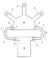
図2に、図1に示される減圧脱泡装置10の第1減圧脱泡部11をII−II線で切断して展開した図を示す。
なお、第1減圧脱泡部11と第2減圧脱泡部12は、互いに対称となることを除いて基本的に同様に構成されるので、以下、主に第1減圧脱泡部11について説明し、第2減圧脱泡部12についての説明は基本的に省略する。
【0019】
同図に示されるように、第1減圧脱泡部11は、減圧ハウジング13と、減圧脱泡槽14と、上昇管16と、下降管18とを有する。
減圧ハウジング13は、減圧脱泡槽14の気密性を確保するためのものであり、その上部13cが水平方向にU字型に形成され、脚部13a,13bがU字の両端近傍から下方に突出して形成される。従って、図1におけるII−II線の断面形状は、図2に示すように略門型となっている。この減圧ハウジング13は、減圧脱泡槽14に必要とされる気密性および強度を有するものであれば、その材質、構造は特に限定されるものではないが、金属製、特にステンレス製とするのが好ましい。このような減圧ハウジング13は、外部から真空ポンプ(図示せず)等によって真空吸引され、内部が減圧され、内設される減圧脱泡槽14内を所定の減圧、例えば1/20〜1/3気圧の減圧状態に維持するように構成される。
【0020】
減圧ハウジング13の上部13c内にはU字型の減圧脱泡槽14が設けられる。また、減圧脱泡槽14の左端部近傍には上昇管16が連通され、減圧脱泡槽14の右端部近傍には下降管18が連通される。なお、上昇管16および下降管18はそれぞれ減圧ハウジング13の脚部内に配設されている。
【0021】
本発明の減圧脱泡装置10においては、減圧脱泡槽14、上昇管16および下降管18の材質は特に限定されず、白金または白金合金などの貴金属合金や、電鋳耐火物などが挙げられるが、中でも電鋳耐火物を用いるのが好ましい。すなわち、減圧脱泡装置10における溶融ガラスGと直接接触する主要部分を電鋳耐火物で形成することにより、従来から用いられてきた白金合金製のものよりも、コストが大幅に低減し、従って自由な形状で、かつ、自由な厚さに設計することが可能となることから、減圧脱泡装置10の大容量化が実現するとともに、より高温での減圧脱泡処理も行えるようになるからである。
【0022】
なお、電鋳耐火物を用いる場合であっても、上昇管16の下端であって、ピット22内の溶融ガラスGに浸漬する部分や、下降管18の下端であって、ピット52内の溶融ガラスGに浸漬する部分については、特に溶融ガラスGと大気との界面が存在することから、この界面近傍においては反応性に富み、特に電鋳耐火物では界面部分や目地部分の劣化が進行しやすい。従って、上昇管16の下端部および下降管18の下端部は、白金または白金合金で作製するのが好ましい。
【0023】
電鋳耐火物としては、耐火原料を電気溶融した後、所定形状に鋳込み成形したレンガであれば特に限定されず、従来公知の各種の電鋳耐火物を使用すればよい。中でも、耐蝕性が高く、素地からの発泡も少ない点で、アルミナ系電鋳耐火物、ジルコニア系電鋳耐火物、AZS系電鋳耐火物等が好適に例示され、具体的には、マースナイト(MB−G)、ZB−X950、ジルコナイト(ZB)(いずれも旭硝子(株)製)等が挙げられる。
【0024】
減圧脱泡槽14の形状は、上述したように、少なくとも水平方向にU字型に形成された筒体であれば特に限定されず、上昇管16および下降管18の形状は少なくとも筒状であれば特に限定されない。従って、減圧脱泡槽14、上昇管16および下降管18の断面形状は円状のみならず矩形状であってもよい。
また、電鋳レンガを用いて減圧脱泡槽14、上昇管16および下降管18を構築する場合、その方法は、特に制限的ではなく、例えば比較的小さな直方体の電鋳レンガを積み上げてもよいし、円筒状もしくは角筒状に鋳込み成形した筒状の電鋳レンガを一列に積み重ねて、その間の目地の部分を目地材で埋め、所定長の筒状管を形成してもよい。
【0025】
上昇管16の設置位置としては、溶解槽20から溶融ガラスGを導入できる位置であれば特に限定されないが、例えば、図1に示されるように、溶解槽20の左右にピット22が形成されている場合には、このピット22内に上昇管16の下端を挿入して、溶融ガラスGに浸漬させる構成とすれば、既存の設備を有効に活用することができるので好ましい。
一方、下降管18の設置位置としては、作業槽50に溶融ガラスGを導出しうる位置であれば特に限定されず、例えば、図1に示されるように、作業槽50の左右に形成されるピット52内に下降管16の下端を挿入し、溶融ガラスGに浸漬させる構成とすればよい。
【0026】
そして、減圧脱泡槽14の周囲には減圧脱泡槽14を被覆する断熱用のレンガ32(以下、断熱レンガ32とする)が配設され、上昇管16および下降管18の周囲にはそれぞれを被覆する断熱レンガ32が配設される。
断熱レンガ32としては、公知の種々のレンガを使用すればよく、特に限定されない。このように配設された断熱レンガ32は、その外側が減圧ハウジング13に覆われることにより減圧ハウジング13内に収容される。なお、減圧ハウジング13の外側の温度は、断熱レンガ32によってできるだけ減圧ハウジング13に伝達される熱を遮断して、できるだけ低温、好ましくは200℃以下、例えば100℃程度にするのが好ましい。
【0027】
また、減圧脱泡槽14、上昇管16および下降管18の周囲には、必要に応じて、断熱レンガ32とともに、加熱ヒータを設けて加熱可能な構成としてもよいし、冷却水を通過可能にして冷却可能な構成としてもよい。
【0028】
このような減圧脱泡部11,12により減圧脱泡処理が施された溶融ガラスGは、それぞれの下降管18,19およびピット52,52を介して、作業槽50に到達する。
図示例の作業槽50は、瓶の成形を行う部分であり、平面がおおむね半月状に形成されるとともに、この作業槽50から複数本(例えば3〜5本)のフォアハース54が放射状に設けられる。
【0029】
なお、作業槽50としては、図示例の瓶の成形用に限らず、溶融ガラスGの攪拌、成形等の処理を行う各種の処理槽であれば特に限定されない。例えば、作業槽50を板材の成形処理槽とする場合には、矩形状に形成されるとともに、この作業槽からキャナルが1本または2本平行して設けられる。いずれにしても、このフォアハース54やキャナルにおいて、瓶、板ガラス等のガラス成形品が製造される。
【0030】
なお、下降管18,19の下流側で、かつ、作業槽50内には、2本の減圧脱泡部11,12より供給された溶融ガラスGを合流し攪拌する攪拌装置を設けてもよい。
攪拌装置としては、溶融ガラスの攪拌に用いられる公知の種々の攪拌装置を用いればよく、特に限定されるものではない。例えば、攪拌装置は、溶融ガラスGを攪拌するための空間を確保するための攪拌槽と、この攪拌槽内に収容され、溶融ガラスGの攪拌を行うスターラと、このスターラを回転駆動する駆動モータとから構成すればよい。このような攪拌装置を有することにより、2本の下降管18,19から供給された溶融ガラスGを強制的に攪拌して均一化することができるので、光学的特性により優れたガラスを得ることができる。
【0031】
ここで、本発明の減圧脱泡装置10の処理対象となる溶融ガラスGは、特に制限的ではなく、例えば、ソーダ石灰ガラスやホウケイ酸ガラスなどを挙げることができるが、本発明の減圧脱泡装置10は多量の溶融ガラスを処理することができることから、多量の処理が必要とされるソーダ石灰ガラスを処理対象とするのが好ましい。また、ソーダ石灰ガラスを処理対象とすることにより、減圧脱泡槽14の減圧度を低く設定することが可能となることから、本発明に係る減圧脱泡部14のU字型形状と相まって、減圧脱泡槽14の高さを低く(例えば、2〜3m)することができる。従って、既存の設備を有効に活用しつつ、高さ方向のコンパクト化を図ることができる。
【0032】
ところで、図示例の減圧脱泡装置10は、第1減圧脱泡部11および第2減圧脱泡部12とを有する並列式であるため、これら2本の減圧脱泡部11,12で減圧脱泡処理を行われることとなる。従って、さらなる大量の溶融ガラスGの減圧脱泡処理が可能となり、生産量の変動に対しても、例えば一方の減圧脱泡部11または12のみ運転する等の、機動的な対応が可能となる。
特に、図1に示されるように溶解槽20の左右のピット22,22から均等に溶融ガラスGを導出する構成とすれば、溶解槽20内で溶融ガラスGが左右のいずれかに偏って流れることがないので、不均一な対流の発生を防止し、従って、均質性により優れた溶融ガラスを得ることも可能となる。
【0033】
また、減圧脱泡部11または12の一方が、メンテナンス等により使用不能となった場合においても、他方の減圧脱泡部11または12は単独で引き続き使用することができ、ガラス製品の製造への支障を最小限に抑えることもできる。特に、減圧脱泡槽14、上昇管16および下降管18等を白金または白金合金で構成した場合、仮にこれらが破損し、その修理に数カ月を要したとしても、片方の減圧脱泡部11または12のみで運転が可能であることから極めて有効である。
【0034】
なお、本発明の減圧脱泡装置は、上記図示例の並列型に限定されず、第1減圧脱泡部11または第2減圧脱泡部12の1本のみから構成してもよいのはもちろんである。この場合には、図1の場合と同様にして、溶解槽20および作業槽50のいずれか一方の側方部を連結するように減圧脱泡装置を設ける構成としてもよいし、溶解槽20および作業槽50の中央部を連結するように減圧脱泡装置を設ける構成としてもよい。また、減圧脱泡槽14の端部の向きに沿って直線的に溶解槽20および作業槽50の少なくとも一方を配置する構成としてもよい。いずれにしても、このような1本構成の減圧脱泡装置においても、上述した本発明による効果を十分に得ることができる。
【0035】
このような本発明の減圧脱泡装置10で溶融ガラスGを脱泡処理して次の処理炉に連続的に供給するプロセス例を以下に示す。なお、第1減圧脱泡部11と第2減圧脱泡部12は同様に構成されるので、主に減圧脱泡部12についての作用について以下説明する。
まず、溶解槽20において、ガラスを溶融して溶融ガラスGとするが、このときの温度は、ソーダ石灰ガラスの場合には1250〜1450℃、好ましくは1280〜1320℃である。この範囲内であると、溶融ガラスGの粘性を十分に小さくし、効率的な減圧脱泡処理が可能となり、装置(特に白金または白金合金)の劣化を抑えることもできる。なお、ホウケイ酸ガラスなど他の組成のガラスについても、上記ソーダ石灰ガラスと同様の粘性となるような温度に溶融するのが好ましい。
【0036】
そして、図示しない真空ポンプで減圧ハウジング13内および減圧脱泡槽14内を真空吸引状態に維持する。この状態で、溶解槽20で溶融されたガラスGはピット22を通って上昇管16を介して上昇して減圧脱泡槽14内に導かれ、溶融ガラスGは減圧脱泡槽14内で減圧条件下において脱泡処理される。
【0037】
次いで、脱泡処理された溶融ガラスGは下降管18およびピット52を介して作業槽50に導出される。
なお、図示例の減圧脱泡装置10は、第1減圧脱泡部11と第2減圧脱泡部12の2本構成であるので、溶融ガラスGは2本の上昇管でそれぞれの減圧脱泡槽に供給され、2本の下降管で排出されて、作業槽50に供給される。
【0038】
ところで、本発明の溶融ガラスの減圧脱泡装置は、図2に示すサイフォン方式の減圧脱泡装置のみならず、特開平5−262530号公報、特開平7−291633号公報に示す水平式減圧脱泡装置にも適用してもよいのはもちろんである。
以上、本発明の溶融ガラスの減圧脱泡装置について詳細に説明したが、本発明は上記実施例に限定されず、本発明の要旨を逸脱しない範囲において、各種の改良および変更を行ってもよいのはもちろんである。
【0039】
【発明の効果】
以上、詳細に説明したように、本発明によれば、連続的に供給される溶融ガラスから気泡を除去する、溶融ガラスの減圧脱泡装置において、大量の溶融ガラスを処理することができ、装置の安全性にも優れるとともに、既存の設備を有効に活用することができる。
また、並列式の減圧脱泡装置として構成すれば、さらなる処理流量の増大が図れるとともに、生産量の変動に対しても機動的に対応でき、より均質性に優れた溶融ガラスを得ることが可能となる。
【図面の簡単な説明】
【図1】 本発明の減圧脱泡装置を溶解槽と作業槽との間に適用した一例を示す概略平面図である。
【図2】 図1に示される減圧脱泡装置における減圧脱泡部をII−II線で切断して展開した断面図である。
【図3】 従来における減圧脱泡装置を溶解槽と作業槽との間に適用した一例を示す概略平面図である。
【図4】 図3に示される減圧脱泡装置における減圧脱泡部をIV−IV線で切断して展開した断面図である。
【符号の説明】
10 並列式減圧脱泡装置
11 第1の減圧脱泡装置(第1減圧脱泡部)
12 第2の減圧脱泡装置(第2減圧脱泡部)
13 減圧ハウジング
13a,13b 減圧ハウジング脚部
13c 減圧ハウジング上部
14,15 減圧脱泡槽
16 上昇管
18,19 下降管
20 溶解槽
22 ピット
32 断熱レンガ
50 作業槽
52 ピット
54 フォアハース
100 減圧脱泡装置
102 溶解槽
104 減圧ハウジング
106 減圧脱泡槽
108 上昇管
110 下降管
112 断熱材
114 作業槽 [0001]
BACKGROUND OF THE INVENTION
The present invention belongs to the technical field of a vacuum degassing apparatus for molten glass that removes bubbles from continuously supplied molten glass.
[0002]
[Prior art]
Conventionally, in order to improve the quality of a molded glass product, a vacuum degassing apparatus that removes bubbles generated in the molten glass before the molten glass melted in the melting furnace is molded by a molding apparatus has been used. . FIG. 3 shows an example of a possible arrangement when a conventional vacuum degassing apparatus is applied between a dissolution tank and a working tank, and FIG. 4 shows a vacuum degassing apparatus shown in FIG. The figure which cut | disconnected by the IV line and expand | deployed is shown.
As shown in FIG. 3, the conventional
[0003]
The ascending
[0004]
Since the conventional
Here, these are constituted by noble metal circular tubes such as platinum alloys because not only the molten glass G is hot, but also the noble metal has low high temperature reactivity with the molten glass and is inhomogeneous due to reaction with the molten glass. This is because the strength at a high temperature can be secured to some extent without causing any deterioration.
In particular, the
[0005]
[Problems to be solved by the invention]
By the way, when the
[0006]
For such a problem, it is also conceivable to increase the defoaming amount by increasing the overall length of the tubular
Furthermore, if the vacuum degassing tank is linearly long, the amount of expansion of the
[0007]
By the way, when the molten glass G is soda-lime glass, since the viscosity is lower than that of other glasses such as borosilicate glass, it is possible to set the degree of vacuum of the vacuum degassing tank low. For this reason, it is possible to reduce the height of the vacuum degassing apparatus (for example, 2 to 3 m) according to the degree of vacuum of the vacuum degassing tank, and to reduce the height of the vacuum degassing apparatus. It is done.
[0008]
However, if it is actually applied to existing equipment, the following inconvenience occurs. That is, in FIG. 3, in the conventional kiln, the
[0009]
An object of the present invention is to solve the problems of the prior art, and to process a large amount of molten glass in a vacuum degassing apparatus for molten glass that removes bubbles from continuously supplied molten glass. It is possible to provide a vacuum degassing apparatus for molten glass, which is excellent in safety of the apparatus and can effectively use existing equipment.
[0010]
[Means for Solving the Problems]
In order to achieve the above object, the present invention provides a vacuum housing that is evacuated, a vacuum defoaming tank that is provided in the vacuum housing and degassed molten glass, and communicates with the vacuum degassing tank. And introducing means for introducing molten glass before vacuum degassing into the vacuum degassing tank; and communicating with the vacuum degassing tank; and providing the molten glass after vacuum degassing from the vacuum degassing tank Deriving means for deriving, wherein the vacuum degassing tank and the vacuum housing around the vacuum degassing tank are formed in a U-shape in the horizontal direction. Providing equipment.
[0011]
Here, the introduction means is a riser pipe that raises the molten glass before vacuum degassing and introduces it into the vacuum degassing tank, and the derivation means lowers the molten glass after vacuum degassing and lowers the pressure reduction It is preferable that it is a downcomer pipe | tube derived | led-out from a defoaming tank.
Moreover, it is preferable that the vacuum degassing tank is formed of an electroformed refractory at least at a portion that directly contacts the molten glass.
Furthermore, the molten glass is preferably soda lime glass.
[0012]
Moreover, this invention provides the vacuum degassing apparatus of the molten glass which has two said vacuum degassing apparatuses of the molten glass in parallel.
[0013]
DETAILED DESCRIPTION OF THE INVENTION
Hereinafter, the vacuum degassing apparatus of the present invention will be described in detail based on a preferred embodiment shown in the accompanying drawings.
[0014]
In FIG. 1, the schematic sectional drawing of an example which applied the vacuum degassing apparatus of this invention between the dissolution tank and the working tank is shown.
A vacuum degassing apparatus 10 (hereinafter, referred to as a vacuum degassing apparatus 10) shown in FIG. 1 is continuously connected to a
[0015]
Here, as described above, in the conventional vacuum degassing apparatus in which the vacuum degassing tank is constituted by a precious metal circular tube, a large-flow vacuum degassing apparatus cannot be constructed in terms of both cost and strength. Even when the total length of the defoaming tank is increased and the flow rate is increased to increase the amount of defoaming, the apparatus becomes longer and there is a problem that the existing equipment cannot be used effectively. There is also a problem that the safety of the apparatus may be impaired, for example, the expansion of the vacuum degassing tank accompanying heating causes the center distance between the ascending pipe and the descending pipe to be shifted to cause distortion in the apparatus. Furthermore, if the molten glass is soda-lime glass, the height of the vacuum degassing device can be reduced, but it will be necessary to change the positional relationship of each existing device, and the existing equipment must still be used effectively. There is a problem that can not be.
[0016]
Therefore, as shown in FIG. 1, the vacuum degassing apparatus of the present invention has a U-shaped
[0017]
Further, the thermal expansion of the
Furthermore, even when the height of the apparatus is lowered, it can be provided so as to avoid the roof (not shown) of the
[0018]
FIG. 2 shows a developed view of the first
The first
[0019]
As shown in the figure, the first
The
[0020]
A U-shaped
[0021]
In the
[0022]
Even when an electroformed refractory is used, it is the lower end of the
[0023]
The electrocast refractory is not particularly limited as long as it is a brick that is obtained by electrically melting a refractory raw material and then cast into a predetermined shape, and various conventionally known electrocast refractories may be used. Among these, alumina-based electrocast refractories, zirconia-based electrocast refractories, AZS-based electrocast refractories and the like are preferable examples because they have high corrosion resistance and little foaming from the substrate. Specifically, marsnite (MB-G), ZB-X950, zirconite (ZB) (all manufactured by Asahi Glass Co., Ltd.) and the like.
[0024]
The shape of the
Moreover, when constructing the
[0025]
The installation position of the
On the other hand, the position where the
[0026]
A heat insulating brick 32 (hereinafter referred to as a heat insulating brick 32) covering the
As the
[0027]
Moreover, it is good also as a structure which can provide a heating heater with the
[0028]
The molten glass G that has been subjected to the vacuum degassing process by the
The working
[0029]
The working
[0030]
A stirring device that joins and stirs the molten glass G supplied from the two
As the stirring device, various known stirring devices used for stirring molten glass may be used, and the stirring device is not particularly limited. For example, the stirring device includes a stirring tank for securing a space for stirring the molten glass G, a stirrer that is contained in the stirring tank and that stirs the molten glass G, and a drive motor that rotationally drives the stirrer. May be configured. By having such a stirrer, the molten glass G supplied from the two
[0031]
Here, the molten glass G to be processed by the
[0032]
By the way, since the
In particular, as shown in FIG. 1, if the molten glass G is evenly led out from the left and
[0033]
Further, vacuum one degassing
[0034]
Note that the vacuum degassing apparatus of the present invention is not limited to the parallel type in the illustrated example, and may be configured by only one of the first
[0035]
An example of a process in which the molten glass G is defoamed with the
First, in the
[0036]
And the inside of the
[0037]
Next, the defoamed molten glass G is led to the
In addition, since the
[0038]
By the way, the vacuum degassing apparatus for molten glass of the present invention is not limited to the siphon type vacuum degassing apparatus shown in FIG. 2, but also the horizontal vacuum degassing apparatus shown in JP-A-5-262530 and JP-A-7-291633. Of course, it may also be applied to the foam device.
As mentioned above, although the vacuum degassing apparatus of the molten glass of this invention was demonstrated in detail, this invention is not limited to the said Example, You may perform various improvement and change in the range which does not deviate from the summary of this invention. Of course.
[0039]
【The invention's effect】
As described above in detail, according to the present invention, a large amount of molten glass can be processed in a vacuum degassing apparatus for molten glass that removes bubbles from continuously supplied molten glass. As well as being excellent in safety, existing facilities can be used effectively.
In addition, if it is configured as a parallel-type vacuum degassing device, the processing flow rate can be further increased, and it is possible to flexibly respond to fluctuations in production volume, and it is possible to obtain molten glass with better homogeneity. It becomes.
[Brief description of the drawings]
FIG. 1 is a schematic plan view showing an example in which the vacuum degassing apparatus of the present invention is applied between a dissolution tank and a working tank.
FIG. 2 is a cross-sectional view of the vacuum degassing part shown in FIG. 1 developed by cutting along a line II-II.
FIG. 3 is a schematic plan view showing an example in which a conventional vacuum degassing apparatus is applied between a dissolution tank and a working tank.
4 is a cross-sectional view in which a vacuum degassing part in the vacuum degassing apparatus shown in FIG. 3 is developed by cutting along line IV-IV.
[Explanation of symbols]
10 parallel-type
12 2nd vacuum degassing apparatus (2nd vacuum degassing part)
13 Vacuum housing
13a, 13b Decompression housing leg
13c Upper part of
100 Vacuum degassing equipment
102 Dissolution tank
104 decompression housing
106 vacuum degassing tank
108 riser
110 Downcomer
112 Thermal insulation
114 Working tank
Claims (5)
この減圧ハウジング内に設けられ、溶融ガラスの減圧脱泡を行う減圧脱泡槽と、
この減圧脱泡槽に連通して設けられ、減圧脱泡前の溶融ガラスを前記減圧脱泡槽に導入する導入手段と、
前記減圧脱泡槽に連通して設けられ、減圧脱泡後の溶融ガラスを前記減圧脱泡槽から導出する導出手段とを有し、
前記減圧脱泡槽、および前記減圧脱泡槽の周囲の前記減圧ハウジングが、水平方向にU字型に形成されたことを特徴とする溶融ガラスの減圧脱泡装置。A vacuum housing that is vacuumed;
A vacuum degassing tank that is provided in the vacuum housing and performs vacuum degassing of the molten glass;
An introduction means that is provided in communication with the vacuum degassing tank and introduces the molten glass before the vacuum degassing into the vacuum degassing tank;
Provided in communication with the vacuum degassing tank, and having a deriving means for deriving the molten glass after the vacuum degassing from the vacuum degassing tank,
The vacuum degassing apparatus for molten glass, wherein the vacuum degassing tank and the vacuum housing around the vacuum degassing tank are formed in a U-shape in the horizontal direction.
Priority Applications (1)
| Application Number | Priority Date | Filing Date | Title |
|---|---|---|---|
| JP29257397A JP3724153B2 (en) | 1997-10-24 | 1997-10-24 | Vacuum degassing equipment for molten glass |
Applications Claiming Priority (1)
| Application Number | Priority Date | Filing Date | Title |
|---|---|---|---|
| JP29257397A JP3724153B2 (en) | 1997-10-24 | 1997-10-24 | Vacuum degassing equipment for molten glass |
Publications (2)
| Publication Number | Publication Date |
|---|---|
| JPH11130442A JPH11130442A (en) | 1999-05-18 |
| JP3724153B2 true JP3724153B2 (en) | 2005-12-07 |
Family
ID=17783532
Family Applications (1)
| Application Number | Title | Priority Date | Filing Date |
|---|---|---|---|
| JP29257397A Expired - Fee Related JP3724153B2 (en) | 1997-10-24 | 1997-10-24 | Vacuum degassing equipment for molten glass |
Country Status (1)
| Country | Link |
|---|---|
| JP (1) | JP3724153B2 (en) |
Families Citing this family (6)
| Publication number | Priority date | Publication date | Assignee | Title |
|---|---|---|---|---|
| JP4513248B2 (en) * | 2001-09-28 | 2010-07-28 | 旭硝子株式会社 | Vacuum degassing apparatus and vacuum degassing method |
| EP2560370A3 (en) | 2005-12-06 | 2013-07-03 | Panasonic Corporation | Digital camera |
| CN102976587A (en) * | 2012-12-22 | 2013-03-20 | 蚌埠玻璃工业设计研究院 | Clarification method of alumina silicate glass melts |
| CN106830626A (en) * | 2017-04-06 | 2017-06-13 | 蚌埠玻璃工业设计研究院 | A kind of decompression bubble discharge system of electronical display glass melter |
| CN111747634B (en) * | 2020-06-08 | 2022-03-15 | 中建材蚌埠玻璃工业设计研究院有限公司 | High-generation TFT-LCD glass substrate production line |
| CN111704347B (en) * | 2020-06-08 | 2022-03-18 | 中建材蚌埠玻璃工业设计研究院有限公司 | Large-flow noble metal channel |
-
1997
- 1997-10-24 JP JP29257397A patent/JP3724153B2/en not_active Expired - Fee Related
Also Published As
| Publication number | Publication date |
|---|---|
| JPH11130442A (en) | 1999-05-18 |
Similar Documents
| Publication | Publication Date | Title |
|---|---|---|
| EP0908417B1 (en) | Vacuum degassing apparatus for molten glass | |
| EP1298094B1 (en) | Vacuum degassing apparatus for molten glass | |
| JP5016167B2 (en) | Vacuum clarifier | |
| US6405564B1 (en) | Vacuum degassing apparatus for molten glass | |
| KR101271801B1 (en) | Vacuum defoaming equipment, equipment for producing glass product, and method for producing glass product | |
| EP2248774B1 (en) | Vacuum degassing apparatus and vacuum degassing method for molten glass | |
| JP3785788B2 (en) | Vacuum degassing equipment for molten glass | |
| JP3724153B2 (en) | Vacuum degassing equipment for molten glass | |
| US6948338B2 (en) | Vacuum degassing apparatus for molten glass | |
| JP3915268B2 (en) | Vacuum degassing equipment for molten glass | |
| JP5737288B2 (en) | Vacuum degassing apparatus for molten glass, method for producing molten glass, and method for producing glass product | |
| JP3817868B2 (en) | Vacuum degassing equipment for molten glass | |
| JP4103236B2 (en) | Glass manufacturing equipment by vacuum degassing | |
| JP3915288B2 (en) | Vacuum degassing equipment for molten glass | |
| JP3724156B2 (en) | Parallel vacuum deaerator | |
| JP4048646B2 (en) | Vacuum degassing method for molten glass and glass manufacturing apparatus by vacuum degassing | |
| JP4513248B2 (en) | Vacuum degassing apparatus and vacuum degassing method | |
| JPH11240725A (en) | Vacuum deaerator for molten glass | |
| JPH11130444A (en) | Reduced pressure deforming apparatus for molten glass |
Legal Events
| Date | Code | Title | Description |
|---|---|---|---|
| A977 | Report on retrieval |
Free format text: JAPANESE INTERMEDIATE CODE: A971007 Effective date: 20050822 |
|
| TRDD | Decision of grant or rejection written | ||
| A01 | Written decision to grant a patent or to grant a registration (utility model) |
Free format text: JAPANESE INTERMEDIATE CODE: A01 Effective date: 20050830 |
|
| A61 | First payment of annual fees (during grant procedure) |
Free format text: JAPANESE INTERMEDIATE CODE: A61 Effective date: 20050912 |
|
| R150 | Certificate of patent or registration of utility model |
Free format text: JAPANESE INTERMEDIATE CODE: R150 |
|
| FPAY | Renewal fee payment (event date is renewal date of database) |
Free format text: PAYMENT UNTIL: 20080930 Year of fee payment: 3 |
|
| FPAY | Renewal fee payment (event date is renewal date of database) |
Free format text: PAYMENT UNTIL: 20090930 Year of fee payment: 4 |
|
| FPAY | Renewal fee payment (event date is renewal date of database) |
Free format text: PAYMENT UNTIL: 20090930 Year of fee payment: 4 |
|
| FPAY | Renewal fee payment (event date is renewal date of database) |
Free format text: PAYMENT UNTIL: 20100930 Year of fee payment: 5 |
|
| FPAY | Renewal fee payment (event date is renewal date of database) |
Free format text: PAYMENT UNTIL: 20100930 Year of fee payment: 5 |
|
| FPAY | Renewal fee payment (event date is renewal date of database) |
Free format text: PAYMENT UNTIL: 20110930 Year of fee payment: 6 |
|
| FPAY | Renewal fee payment (event date is renewal date of database) |
Free format text: PAYMENT UNTIL: 20110930 Year of fee payment: 6 |
|
| FPAY | Renewal fee payment (event date is renewal date of database) |
Free format text: PAYMENT UNTIL: 20120930 Year of fee payment: 7 |
|
| FPAY | Renewal fee payment (event date is renewal date of database) |
Free format text: PAYMENT UNTIL: 20120930 Year of fee payment: 7 |
|
| S531 | Written request for registration of change of domicile |
Free format text: JAPANESE INTERMEDIATE CODE: R313531 |
|
| FPAY | Renewal fee payment (event date is renewal date of database) |
Free format text: PAYMENT UNTIL: 20120930 Year of fee payment: 7 |
|
| R371 | Transfer withdrawn |
Free format text: JAPANESE INTERMEDIATE CODE: R371 |
|
| S531 | Written request for registration of change of domicile |
Free format text: JAPANESE INTERMEDIATE CODE: R313531 |
|
| FPAY | Renewal fee payment (event date is renewal date of database) |
Free format text: PAYMENT UNTIL: 20120930 Year of fee payment: 7 |
|
| R350 | Written notification of registration of transfer |
Free format text: JAPANESE INTERMEDIATE CODE: R350 |
|
| FPAY | Renewal fee payment (event date is renewal date of database) |
Free format text: PAYMENT UNTIL: 20130930 Year of fee payment: 8 |
|
| LAPS | Cancellation because of no payment of annual fees |