JP3817868B2 - Vacuum degassing equipment for molten glass - Google Patents
Vacuum degassing equipment for molten glass Download PDFInfo
- Publication number
- JP3817868B2 JP3817868B2 JP30532697A JP30532697A JP3817868B2 JP 3817868 B2 JP3817868 B2 JP 3817868B2 JP 30532697 A JP30532697 A JP 30532697A JP 30532697 A JP30532697 A JP 30532697A JP 3817868 B2 JP3817868 B2 JP 3817868B2
- Authority
- JP
- Japan
- Prior art keywords
- pipe
- vacuum degassing
- molten glass
- vacuum
- tank
- Prior art date
- Legal status (The legal status is an assumption and is not a legal conclusion. Google has not performed a legal analysis and makes no representation as to the accuracy of the status listed.)
- Expired - Fee Related
Links
Images


Classifications
-
- C—CHEMISTRY; METALLURGY
- C03—GLASS; MINERAL OR SLAG WOOL
- C03B—MANUFACTURE, SHAPING, OR SUPPLEMENTARY PROCESSES
- C03B5/00—Melting in furnaces; Furnaces so far as specially adapted for glass manufacture
- C03B5/16—Special features of the melting process; Auxiliary means specially adapted for glass-melting furnaces
- C03B5/225—Refining
- C03B5/2252—Refining under reduced pressure, e.g. with vacuum refiners
Landscapes
- Chemical & Material Sciences (AREA)
- Engineering & Computer Science (AREA)
- Materials Engineering (AREA)
- Organic Chemistry (AREA)
- Manufacture And Refinement Of Metals (AREA)
Description
【0001】
【発明の属する技術分野】
本発明は、連続的に供給される溶融ガラスから気泡を除去する、溶融ガラスの減圧脱泡装置の技術分野に属する。
【0002】
【従来の技術】
従来より、成形されたガラス製品の品質を向上させるために、溶融炉で溶融した溶融ガラスを成形装置で成形する前に溶融ガラス内に発生した気泡を除去する減圧脱泡装置が用いられている。このような従来の減圧脱泡装置を図3に示す。図3に示す減圧脱泡装置100は、溶解槽112中の溶融ガラスGを減圧脱泡処理して、次の処理槽に連続的に供給するプロセスに用いられるものであって、真空吸引されている。減圧ハウジング102内に水平に減圧脱泡槽104が収納配置され、その両端に垂直に取り付けられる上昇管106および下降管108が収納配置されている。
【0003】
上昇管106は減圧脱泡槽104に連通し、脱泡処理前の溶融ガラスGを溶解槽112から上昇させて減圧脱泡槽104に導入する。下降管108は、減圧脱泡槽104に連通し、脱泡処理後の溶融ガラスGを減圧脱泡槽104から下降させて次の処理槽(図示せず)に導出する。そして、減圧ハウジング102内において、減圧脱泡槽104、上昇管106および下降管108の周囲には、これらを断熱被覆する断熱用レンガなどの断熱材110が配設されている。なお、減圧ハウジング102は、金属製、例えばステンレス製であり、外部から真空ポンプ(図示せず)等によって真空吸引され、内部が減圧され、内設される減圧脱泡槽104内を所定の減圧、例えば1/20〜1/3気圧の減圧状態に維持する。
【0004】
従来の減圧脱泡装置100においては、高温、例えば1200〜1400℃の温度の溶融ガラスGを処理するように構成されているので、本出願人の出願に係る特開平2−221129号公報に開示しているように、減圧脱泡槽104、上昇管106および下降管108などのように溶融ガラスGと直接接触する部分は、通常白金または白金ロジウムのような白金合金などの貴金属製円管で構成されている。
ここで、これらを白金合金などの貴金属製円管で構成するのは、溶融ガラスGが高温であるばかりでなく、貴金属が溶融ガラスとの高温反応性が低く、溶融ガラスとの反応による不均質化を生じさせることがなく、高温での強度がある程度確保できるからである。
特に、減圧脱泡槽104を貴金属製円管で構成するのは、上記理由に加え、貴金属製円管自体に電流を流して自己発熱させ、円筒内の溶融ガラスGを均一に加熱し、溶融ガラスGの温度を所定の温度に保持するためである。
【0005】
ところで、減圧脱泡槽104を貴金属で構成すると、高温強度の点から円管とするのがよいが、白金などの貴金属は高価であるため、肉厚を大きくできない。よって、コストおよび強度の両方の点から円管の直径には限界があり、あまり円管の直径を大きくできず、減圧脱泡槽104で脱泡処理できる溶融ガラスGの流量にも限界があり、大流量の減圧脱泡装置を構築できないという問題があった。もちろん、円管状減圧脱泡槽104の全長を長くして流速を速くすることにより、脱泡処理量を増加させることも考えられるが、処理量に比して、また溶解槽や成形処理槽などに比べて、装置が長大化してしまうという問題もあった。このため、減圧脱泡装置100における溶融ガラスGの脱泡処理量(流量)を大きくできないという問題もあった。
【0006】
なお、溶融ガラスGは、粉体原料を溶解反応させることによって得られるので、溶解の点では、溶解槽112の温度は高い方が好ましく、また、減圧脱泡の点では溶融ガラスの粘度は低く、従って温度は高い方が好ましい。しかしながら、高温強度の点から減圧脱泡槽104などに貴金属合金を用いる必要がある一方で、貴金属は高価なものであり、コストの点から円管の厚みをあまり厚くできないため、白金などの貴金属を用いると、減圧脱泡装置100の入口での溶融ガラスGの温度は、上述した所定温度(1200〜1400℃)に制限されてしまっていた。
【0007】
【発明が解決しようとする課題】
ところで、このような問題に対し、減圧脱泡槽104、上昇管106および下降管108を貴金属合金よりも安価な耐火物レンガで構成し、貴金属合金の場合と同様に溶融ガラスを連続的に減圧脱泡処理することができれば、白金などの貴金属合金を用いる場合に比べて、コストの点から使用量を制限したり、それに伴う強度低下の点から大きさを制限したりする必要性はなくなり、装置設計の自由度が飛躍的に向上することから、大流量の減圧脱泡装置の構築が可能になるとともに、より高温での減圧脱泡処理も可能になるものと考えられる。
【0008】
しかしながら、減圧脱泡装置100のすべての構成部分を耐火物レンガで作製しようとすると、以下のような問題がある。すなわち、上昇管106や下降管108の下端部分などの管状の開放端においては、下端を支持するものが無いため、高重量の耐火物レンガを目地材の接着力のみで支持することとなってしまい、十分な強度が得られないし、その代わりに、長い円筒型の耐火物レンガを製造しようとしても、コストが非常に高くなる。このため、上昇管106や下降管108の下端部分を耐火物レンガで作製するのは現実的には困難であるという問題がある。
【0009】
また、このようにして上昇管106や下降管108の下端を耐火物レンガで作製したとしても、目地の部分で損傷や劣化が起こりやすいし、目地以外の部分であっても、溶解槽112における溶融ガラスGと大気との界面近傍の位置では、高温で、かつ、大気が存在することから、耐火物が反応性に富み、選択的に劣化しやすいという問題がある。このように目地部分や界面部分が劣化していくと、上昇管106や下降管108の下端部分が高さ方向に不均一な形状となり、割れなどの破損を生じたり、最悪の場合、上昇管106や下降管108の下端部分の一部が破断して落下してしまうおそれがあり、十分な耐久性が得られないという問題がある。さらに、破損した耐火物が溶融ガラスGに混入すれば、ガラスの組成の均一性を保持できなくなるおそれもあるという問題もある。
【0010】
本発明の目的は、前記従来技術の問題点を解決することにあり、連続的に供給される溶融ガラスから気泡を除去する、溶融ガラスの減圧脱泡装置において、高温の溶融ガラスに対して十分な耐久性を確保しつつ、コストを大幅に低減でき、ひいては装置の大容量化、減圧脱泡処理温度の高温化などを図ることができる溶融ガラスの減圧脱泡装置を提供することにある。
【0011】
【課題を解決するための手段】
前記目的を達成するために、本発明は、真空吸引される減圧ハウジングと、この減圧ハウジング内に設けられ、溶融ガラスの減圧脱泡を行う減圧脱泡槽と、この減圧脱泡槽に連通して設けられ、前記減圧脱泡前の溶融ガラスを上昇させて前記減圧脱泡槽に導入する上昇管と、前記減圧脱泡槽に連通して設けられ、前記減圧脱泡後の溶融ガラスを前記減圧脱泡槽から下降させて導出する下降管と、前記上昇管および下降管の下端にそれぞれ連通して設けられる延長管とを有し、前記上昇管、前記減圧脱泡槽および前記下降管は、少なくとも前記溶融ガラスと直接接触する部分が電鋳レンガで形成され、前記延長管は、白金または白金合金で形成されたことを特徴とする溶融ガラスの減圧脱泡装置を提供する。
【0012】
また、前記延長管は、その上端にフランジが形成され、このフランジが前記上昇管もしくは前記下降管を形成する前記電鋳レンガの目地に挿入されて挟持されることにより、前記上昇管もしくは前記下降管に固定されたものであるのが好ましい。
【0013】
【発明の実施の形態】
以下、本発明の溶融ガラスの減圧脱泡装置について、添付の図面に示される好適実施例をもとに詳細に説明する。
【0014】
図1に、本発明の溶融ガラスの減圧脱泡装置の概略断面図を示す。
図1に示すように、減圧脱泡装置10は、溶解槽20内の溶融ガラスGを減圧脱泡処理して、図示しない次の処理槽、例えば、フロートバスなどの板状の成形処理槽や瓶などの成形作業槽などに連続的に供給するプロセスに用いられるもので、基本的に、減圧ハウジング12、減圧脱泡槽14、上昇管16、下降管18および延長管26,28を有する。
減圧ハウジング12は、減圧脱泡槽14の気密性を確保するためのものであり、略門型に形成される。この減圧ハウジング12は、減圧脱泡槽14に必要とされる気密性および強度を有するものであれば、その材質、構造は特に限定されるものではないが、金属製、特にステンレス製とするのが好ましい。このような減圧ハウジング12は、外部から真空ポンプ(図示せず)等によって真空吸引され、内部が減圧され、内設される減圧脱泡槽14内を所定の減圧、例えば1/20〜1/3気圧の減圧状態に維持するように構成される。
【0015】
減圧ハウジング12の上部内には減圧脱泡槽14が設けられる。また、減圧脱泡槽14の左端部には上昇管16が連通され、減圧脱泡槽14の右端部には下降管18が連通される。なお、上昇管16および下降管18はそれぞれ減圧ハウジング12の脚部12a,12b(以下、それぞれハウジング脚部12a,12bとする)内に配設されている。
【0016】
本発明の減圧脱泡装置10においては、減圧脱泡槽14、上昇管16および下降管18がいずれも電鋳レンガ30で形成される。
すなわち、減圧脱泡装置10における溶融ガラスGと直接接触する主要部分を電鋳レンガ30で形成することにより、従来から用いられてきた白金合金製のものよりも、コストが大幅に低減し、従って自由な形状で、かつ、自由な厚さに設計することが可能となることから、減圧脱泡装置10の大容量化が実現するとともに、より高温での減圧脱泡処理も行えるようになる。また、電鋳レンガであれば、一般のレンガと比べ高温での耐久性に優れ、成分の溶出も最小限にすることができることから、溶融ガラスの均一性を保つことができる。
【0017】
従って、減圧脱泡槽14、上昇管16および下降管18の形状は少なくとも筒状であれば特に限定されず、例えば、その断面形状は円状のみならず角状であってもよい。電鋳レンガ30を用いて減圧脱泡槽14、上昇管16および下降管18を構築する方法は、特に制限的ではなく、例えば小さい直方体の電鋳レンガ30を積み上げ、その間の目地の部分を目地材で埋めて、所定長の筒状管を形成してもよいし、円筒状もしくは角筒状に鋳込み成形した筒状の電鋳レンガ30を一列に積み重ねて、その間の目地の部分を目地材で埋め、所定長の筒状管を形成してもよい。
【0018】
なお、電鋳レンガ30としては、耐火原料を電気溶融した後、所定形状に鋳込み成形したレンガであれば特に限定されず、従来公知の各種の電鋳レンガを使用すればよい。中でも、耐蝕性が高く、素地からの発泡も少ない点で、アルミナ系電鋳耐火物、ジルコニア系電鋳耐火物、AZS(Al2 O3 −ZrO2 −SiO2 )系電鋳耐火物等が好適に例示され、具体的には、マースナイト(MB−G)、ZB−X950、ジルコナイト(ZB)(いずれも旭硝子(株)製)等が挙げられる。
【0019】
そして、減圧脱泡槽14の周囲には減圧脱泡槽14を被覆する断熱用のレンガ32(以下、断熱レンガ32とする)が配設され、上昇管16および下降管18の周囲にもそれぞれを被覆する断熱レンガ32が配設される。
断熱レンガ32としては、公知の種々のレンガを使用すればよく、特に限定されない。このように配設された断熱レンガ32は、その外側が減圧ハウジング12に覆われることにより減圧ハウジング12内に収容される。
【0020】
また、減圧脱泡槽14、上昇管16および下降管18の周囲には、必要に応じて、断熱レンガ32とともに、加熱ヒータを設けて加熱可能な構成としてもよいし、冷却水を通過可能にして冷却可能な構成としてもよい。
【0021】
ここで、上昇管16の下端部は、上流ピット22の開放端に嵌入され、上流ピット22内の溶融ガラスGに浸漬される必要がある。また、下降管18の下端部も同様に、下流ピット24の開放端に嵌入され、下流ピット24内の溶融ガラスG内に浸漬される必要がある。
ところで、本発明の減圧脱泡装置10は、上述したように、主要部分が電鋳レンガ28で構成されるものである。
【0022】
しかしながら、前述したように、上昇管16の下端部であって上流ピット22に嵌入させて溶融ガラスGに浸漬する部分までを電鋳レンガ30で作製しようとしても、強度やコストの点から現実的には困難であるし、仮に電鋳レンガ30で作製したとしても、目地部分や界面部分が劣化しやすく、割れなどの破損を生じるおそれがあり、十分な耐久性が得られないという問題がある。
また、下降管18の下端部であって、下流ピット24の開放端に嵌入させて溶融ガラスGに浸漬する部分を電鋳レンガ30で作製する場合においても、上記同様の問題がある。
【0023】
これに対し、本発明は、図1に示されるように、上昇管16および下降管18の下端部に白金または白金合金製の延長管26,28を設け、この延長管26,28をそれぞれ上流ピット20および下流ピット24内に嵌入し、内部の溶融ガラスGに浸漬する構成としたものである。このような構成とすることで、電鋳レンガ製の上昇管16および下降管18を直接溶融ガラスGに浸漬する必要がなくなり、上流ピット20および下流ピット24内における、溶融ガラスGに対する耐久性を大幅に向上することができ、上記問題を解決することができる。
【0024】
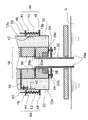
具体的には、図2に示されるように、上昇管16の下端部に白金または白金合金製の延長管26が連通して設けられる。なお、上昇管16側の延長管26と下降管18側の延長管28は同一に構成されているので、上昇管16側の延長管26についてのみ説明し、下降管18側の延長管28の説明は省略する。
【0025】
延長管26は、円筒形状の筒体26aと、この筒体26aの一端に形成される固定用フランジ26bと、この固定用フランジ26bから所定間隔離間して形成されるシール用フランジ26cとを有する管であり、白金または白金合金製である。筒体26aの内径は、上昇管16にスムーズに連通するように、上昇管16の内径とおよそ同等の大きさに構成すればよい。
【0026】
固定用フランジ26bは、上昇管16を構成する電鋳レンガ30,30間、すなわち目地に挿入されることにより、その上端が上昇管16に固定されうるように形成される。
なお、延長管26の上昇管16への固定は、固定用フランジ26bに限らず、種々の方法により行ってもよいが、固定用フランジ26bを用いて固定する構成とするのが好ましい。すなわち、筒体26aの上端に固定用フランジ26bを有しない場合には、筒体26aの外側と電鋳レンガ30との間に溶融ガラスGが浸入し、断熱レンガ32および断熱材38が浸食され、ハウジング脚部12aの底面近傍の熱伝導率が上昇してハウジング外壁面の温度が上がりハウジングが変形するおそれがあるが、筒体26aの上端に固定用フランジ26bを形成することにより、このような問題も解消する。これにより、ハウジング脚部12aの温度上昇、およびこれに伴う下方への歪みを防止し、ハウジング脚部12a内の電鋳レンガ30や断熱レンガ32の目地のずれや緩みに起因する溶融ガラスGの漏れ、ひいてはハウジング脚部12aの過度な温度上昇を防止することができる。
従って、このような部分的な温度上昇に起因する、装置全体の熱応力変形、および溶融ガラスGの漏れの増大による加速度的な温度上昇も防止できる。
【0027】
一方、シール用フランジ26cは、延長管26が下降管18の下端に設けられた際に、後述するシール部材34とともにハウジング脚部12aの下端を外側から閉塞して、減圧ハウジング12内の気密性を確保するためのものである。また、このシール用フランジ26cを電極として、白金または白金合金製の延長管26を自己発熱させて適正温度に保持する構成としてもよい。なお、ハウジング脚部12aの下端において気密性を確保するための機構としては、シール用フランジ26cを用いる方法に限定されず、種々の機構が使用可能である。
延長管26の上昇管16への固定は上述のように固定用フランジ26bに受け持たせるのが好ましいが、シール用フランジ26cに真空シールと延長管26の自重を担持する役目を兼用させ、固定用フランジ26bは電鋳レンガ30aに囲まれた通路内での延長管外面の煉瓦内面からの遊離を防止する役目に限ってもよく、この場合は固定用フランジ26bは延長管26の水平方向の微小な偏芯を防止する役目を担うことになるとともに、延長管外面と煉瓦内面間に溶融ガラスGが浸入することを防ぐ役目も担う。
【0028】
このような延長管26,28に用いる白金または白金合金としては、その組成は特に限定されるものではないが、白金を70wt%〜98wt%含有し、Rhを2wt%以上含有する白金合金であるのが、高温強度が特に優れる点で好ましい。
【0029】
このように構成された延長管26は、固定用フランジ26bが上昇管16の下端近傍の電鋳レンガ30の間の目地部分に挿入されて挟持されるとともに、シール用フランジ26cと減圧ハウジング12との間に、シール部材34が配設され、ハウジング脚部12a下端における気密性が確保される。なお、シール部材34としては、気密性および耐熱性を有するものであれば特に限定されず、ハウジング12の内部も高々1/20気圧に減圧すればよいので、真空装置に用いられる通常の真空シール材料の中から耐熱性のものを選択すればよい。
【0030】
ところで、上述のように延長管26は固定用フランジ26bが電鋳レンガ30の目地に挟持されるが、この際の挟持力は、電鋳レンガ30の自重により確保されることとなる。従って、固定用フランジ26b上に積載される電鋳レンガ30が少ない場合には、溶融ガラスGによる膨張および収縮に伴って目地が開いて挟持力が低下し、固定用フランジ26bを十分に挟持することができず、溶融ガラスGが漏れ出すおそれがある。
このため、延長管26の上方には、図2に示されるように、補強部材36を設け、固定用フランジ26bの電鋳レンガ30による挟持力を補強する構成としてもよい。なお、補強部材36としては、固定用フランジ26bの上方の電鋳レンガ30を下方に押圧することができるものであればよく、その材質および構造は特に限定されるものではない。例えば、固定用フランジ26b上に電鋳レンガ30が高く積載されている場合には、補強部材36を有しなくてもその自重により固定用フランジ26bを強固に挟持することができる。
【0031】
また、図2に示されるように、ハウジング脚部12a内の最下端に設けられた電鋳レンガ30aは、延長管26に面した内側部分であって、ハウジング脚部12aの底面に面した下側隅部分が円周に沿って切り欠かれて形成され、この切欠部に断熱材38が配設されるのが好ましい。すなわち、ハウジング脚部12aの底面のうち、延長管26の周囲近傍は最も加熱されやすいことから、過度に温度上昇して、歪みや変形を生じ、目地からの溶融ガラスGの断熱レンガ層32への漏れを誘発するおそれがある。このため、延長管26の近傍に断熱材38を配設することにより、このハウジング脚部12a底面の過度な温度上昇を防止し、この部分における耐久性をさらに向上させることができる。また、電鋳レンガ30aの下側部分にのみ断熱材38を配設する構成であるので、電鋳レンガ30aの上側部分において十分な強度を確保し、固定用フランジ26bを強固に挟持することができる。
なお、断熱材38としては、電鋳レンガ30よりも断熱性が高い材料であれば特に限定されない。
【0032】
このようにして、上昇管16の下端部であって上流ピット22内の溶融ガラスGに浸漬する部分や、下降管18の下端部であって下流ピット24内の溶融ガラスGに浸漬する部分を白金または白金合金で形成することにより、上昇管16の下端部および下降管18の下端部の劣化や破損を防止し、溶融ガラスGに対して十分な耐久性を確保できる。
【0033】
ところで、ハウジング脚部12aには、緩衝機構40を設け、電鋳レンガ30や断熱レンガ32の上下方向への熱膨張および収縮に応じて伸縮可能な構成とするのが好ましい。こうすることにより、上昇管16を構成する電鋳レンガ30や、その周辺の断熱レンガ32が熱膨張した場合には、緩衝機構40に上昇管16の熱膨張を吸収させることができる一方、これらのレンガが収縮した場合には、その収縮に追随させるようにハウジング脚部12aを収縮させ、収縮に起因する目地の開きを防止して溶融ガラスGの漏れを有効に防ぐことができる。従って、減圧ハウジング12の破損や、これに伴う減圧度の低下を防止し、装置の耐久性および安全性の向上が図れる。
【0034】
具体的には、図2に示すように、緩衝機構40は、筒状ベローズ42と、押し上げ手段44とを有する。筒状ベローズ42は、ハウジング脚部12aが水平方向に切断分離され、この一旦分離されたハウジング脚部12aの上側の部分(以下、上側部13aとする)と、下側の部分(以下、下側部13bとする)とを気密かつ伸縮可能に連結するための部材である。筒状ベローズ42の材質は特に限定されるものではないが、減圧ハウジング12と同様に金属製、特にステンレス製とするのが好ましい。
【0035】
押し上げ手段44は、ハウジング脚部12aの下側部13bを上方に付勢できるものであれば特に限定されず、種々の機構が採用可能である。例えば、図2に示すように、上側部13aと下側部13bとに、互いに対をなして固定される2個の連結部材46,48と、下端が下側の連結部材48に固定され、上側の連結部材46の通過孔を挿通するように設けられる棒材50と、両連結部材46,48間を連結し、下側部13bを上方に付勢する付勢部材52とから構成すればよい。なお、付勢部材52としては、特に限定されないが、コイルばねが好ましく例示される。このように構成することにより、電鋳レンガ30や断熱レンガ32の熱膨張を付勢部材52の付勢力に抗して下方に逃がすことができ、熱膨張に起因する装置の歪みや損傷を防止し、装置の安全性を高めることができる。また、電鋳レンガ30や断熱レンガ32が収縮しても、下側部13bを追随させて、目地の開きを防止することもできる。なお、このような押し上げ手段44は、一本の筒状ベローズ42に対して複数箇所設ける構成とするのが好ましい。
また、ハウジング脚部12aの下端部分は、リブ等で補強する構成としてもよい。
【0036】
このような本発明の減圧脱泡装置10で溶融ガラスGを脱泡処理して次の処理炉に連続的に供給するプロセス例を以下に示す。
まず、図示しない真空ポンプで減圧ハウジング12内および減圧脱泡槽14内を真空吸引状態に維持する。この状態で、溶解槽20で溶融されたガラスGは上流ピット22を通って延長管26および上昇管16を介して上昇して減圧脱泡槽14内に導かれ、溶融ガラスGは減圧脱泡槽14内で減圧条件下において脱泡処理される。そして、脱泡処理された溶融ガラスGは下降管18および延長管28を介して下流ピット24に導かれる。
【0037】
以上、本発明の溶融ガラスの減圧脱泡装置について詳細に説明したが、本発明は上記実施例に限定されず、本発明の要旨を逸脱しない範囲において、各種の改良および変更を行ってもよいのはもちろんである。
【0038】
【発明の効果】
以上、詳細に説明したように、本発明によれば、連続的に供給される溶融ガラスから気泡を除去する、溶融ガラスの減圧脱泡装置において、高温の溶融ガラスに対して十分な耐久性を確保しつつ、コストを大幅に低減でき、ひいては装置の大容量化、減圧脱泡処理温度の高温化などを図ることが可能である。従って、大流量の溶融ガラスの減圧脱泡処理を高効率で行う用途に極めて好適である。
【図面の簡単な説明】
【図1】本発明の減圧脱泡装置の一例を示す概略断面図である。
【図2】図1に示される減圧脱泡装置における、上昇管と延長管との連結部分を示す概略断面図である。
【図3】従来における減圧脱泡装置の一例を示す概略断面図である。
【符号の説明】
10 (溶融ガラスの)減圧脱泡装置
12 減圧ハウジング
12a,12b ハウジング脚部
13a 上側部
13b 下側部
14 減圧脱泡槽
16 上昇管
18 下降管
20 溶解槽
22 上流ピット
24 下流ピット
26,28 延長管
26a 筒体
26b 固定用フランジ
26c シール用フランジ
30,30a 電鋳レンガ
32 断熱レンガ
34 シール部材
36 補強部材
38 断熱材
40 緩衝機構
42 筒状ベローズ
44 押し上げ手段
46,48 連結手段
50 棒材
52 付勢部材
100 減圧脱泡装置
102 減圧ハウジング
104 減圧脱泡槽
106 上昇管
108 下降管
110 断熱材
112 溶解槽 [0001]
BACKGROUND OF THE INVENTION
The present invention belongs to the technical field of a vacuum degassing apparatus for molten glass that removes bubbles from continuously supplied molten glass.
[0002]
[Prior art]
Conventionally, in order to improve the quality of a molded glass product, a vacuum degassing apparatus that removes bubbles generated in the molten glass before the molten glass melted in the melting furnace is molded by a molding apparatus has been used. . Such a conventional vacuum degassing apparatus is shown in FIG. The
[0003]
The ascending
[0004]
Since the conventional
Here, these are constituted by noble metal circular tubes such as platinum alloys because not only the molten glass G is hot, but also the noble metal has low high temperature reactivity with the molten glass and is inhomogeneous due to reaction with the molten glass. This is because the strength at a high temperature can be secured to some extent without causing any deterioration.
In particular, the
[0005]
By the way, when the
[0006]
In addition, since the molten glass G is obtained by dissolving the powder raw material, the temperature of the
[0007]
[Problems to be solved by the invention]
By the way, with respect to such a problem, the decompression defoaming
[0008]
However, if all the components of the vacuum degassing
[0009]
Even if the lower ends of the ascending
[0010]
An object of the present invention is to solve the above-mentioned problems of the prior art, and in a vacuum degassing apparatus for molten glass that removes bubbles from continuously supplied molten glass, it is sufficient for high-temperature molten glass. An object of the present invention is to provide a vacuum degassing apparatus for molten glass that can significantly reduce costs while ensuring high durability, and that can increase the capacity of the apparatus and increase the temperature of the vacuum defoaming treatment.
[0011]
[Means for Solving the Problems]
In order to achieve the above object, the present invention provides a vacuum housing that is evacuated, a vacuum defoaming tank that is provided in the vacuum housing and degassed molten glass, and communicates with the vacuum degassing tank. A riser pipe that raises the molten glass before the vacuum degassing and introduces it into the vacuum degassing tank; and is provided in communication with the vacuum degassing tank; A downcomer pipe that descends from the vacuum degassing tank, and an extension pipe provided in communication with the lower ends of the ascending pipe and the downcomer pipe, and the ascending pipe, the vacuum defoaming tank, and the downcomer pipe are The present invention provides a vacuum degassing apparatus for molten glass, wherein at least a portion in direct contact with the molten glass is formed of an electroformed brick, and the extension tube is formed of platinum or a platinum alloy.
[0012]
The extension pipe has a flange formed at the upper end thereof, and the flange is inserted into a joint of the electroformed brick forming the rise pipe or the down pipe, so that the rise pipe or the down pipe is inserted. It is preferably fixed to a tube.
[0013]
DETAILED DESCRIPTION OF THE INVENTION
Hereinafter, the vacuum degassing apparatus for molten glass of the present invention will be described in detail based on preferred embodiments shown in the accompanying drawings.
[0014]
In FIG. 1, the schematic sectional drawing of the vacuum degassing apparatus of the molten glass of this invention is shown.
As shown in FIG. 1, the
The
[0015]
A
[0016]
In the
That is, by forming the main part in direct contact with the molten glass G in the
[0017]
Accordingly, the shape of the
[0018]
The
[0019]
A heat insulating brick 32 (hereinafter referred to as a heat insulating brick 32) covering the
As the
[0020]
Moreover, it is good also as a structure which can provide a heating heater with the
[0021]
Here, the lower end portion of the ascending
By the way, as described above, the
[0022]
However, as described above, even if the lower end portion of the rising
Further, when the
[0023]
On the other hand, in the present invention, as shown in FIG. 1,
[0024]
Specifically, as shown in FIG. 2, an
[0025]
The
[0026]
The fixing
The
Therefore, it is also possible to prevent the temperature from increasing due to the partial temperature increase, and the thermal stress deformation of the entire apparatus and the increase in leakage of the molten glass G.
[0027]
On the other hand, the sealing
As described above, the
[0028]
The composition of platinum or a platinum alloy used for
[0029]
The
[0030]
By the way, as described above, the
For this reason, as shown in FIG. 2, a reinforcing
[0031]
Further, as shown in FIG. 2, the
The
[0032]
In this way, the lower end portion of the ascending
[0033]
By the way, it is preferable that the
[0034]
Specifically, as shown in FIG. 2, the
[0035]
The push-up means 44 is not particularly limited as long as it can urge the
Further, the lower end portion of the
[0036]
An example of a process in which the molten glass G is defoamed with the
First, the inside of the
[0037]
As mentioned above, although the vacuum degassing apparatus of the molten glass of this invention was demonstrated in detail, this invention is not limited to the said Example, You may perform various improvement and change in the range which does not deviate from the summary of this invention. Of course.
[0038]
【The invention's effect】
As described above in detail, according to the present invention, in a vacuum degassing apparatus for molten glass that removes bubbles from continuously supplied molten glass, sufficient durability against high-temperature molten glass is achieved. While securing the cost, the cost can be greatly reduced, and as a result, the capacity of the apparatus can be increased and the temperature of the vacuum degassing treatment can be increased. Therefore, it is very suitable for the use which performs the depressurization process of the molten glass of a large flow rate with high efficiency.
[Brief description of the drawings]
FIG. 1 is a schematic sectional view showing an example of a vacuum degassing apparatus of the present invention.
FIG. 2 is a schematic cross-sectional view showing a connecting portion between an ascending pipe and an extension pipe in the vacuum degassing apparatus shown in FIG.
FIG. 3 is a schematic cross-sectional view showing an example of a conventional vacuum degassing apparatus.
[Explanation of symbols]
10 Vacuum Degassing Device 12 (for Molten Glass) Vacuum Housing
12a, 12b Housing leg
13a Upper side
13b
100 Vacuum degassing equipment
102 decompression housing
104 vacuum degassing tank
106 Rise pipe
108 downcomer
110 Insulation
112 Dissolution tank
Claims (2)
この減圧ハウジング内に設けられ、溶融ガラスの減圧脱泡を行う減圧脱泡槽と、
この減圧脱泡槽に連通して設けられ、前記減圧脱泡前の溶融ガラスを上昇させて前記減圧脱泡槽に導入する上昇管と、
前記減圧脱泡槽に連通して設けられ、前記減圧脱泡後の溶融ガラスを前記減圧脱泡槽から下降させて導出する下降管と、
前記上昇管および下降管の下端にそれぞれ連通して設けられる延長管とを有し、
前記上昇管、前記減圧脱泡槽および前記下降管は、少なくとも前記溶融ガラスと直接接触する部分が電鋳レンガで形成され、
前記延長管は、白金または白金合金で形成されており、円筒形状の筒体と、該筒体の一端に形成される固定用フランジと、該固定用フランジから所定間隔離間して形成されるシール用フランジとを有し、
前記延長管は、前記固定用フランジが前記上昇管もしくは下降管を形成する前記電鋳レンガの目地に挿入されて挟持されることにより、前記上昇管もしくは前記下降管に固定されており、
前記シール用フランジと前記減圧ハウジングとの間に、シール部材が配設されることを特徴とする溶融ガラスの減圧脱泡装置。A vacuum housing that is vacuumed;
A vacuum degassing tank that is provided in the vacuum housing and performs vacuum degassing of the molten glass;
A riser pipe which is provided in communication with the vacuum degassing tank and raises the molten glass before the vacuum degassing and introduces it into the vacuum degassing tank;
A downcomer pipe which is provided in communication with the vacuum degassing tank, and descends the molten glass after the vacuum degassing from the vacuum degassing tank;
An extension pipe provided in communication with the lower ends of the ascending pipe and the descending pipe,
The ascending pipe, the vacuum degassing tank, and the downcomer pipe are formed of an electroformed brick at least at a portion that directly contacts the molten glass,
The extension tube is made of platinum or a platinum alloy, and has a cylindrical tube, a fixing flange formed at one end of the tube, and a seal formed at a predetermined distance from the fixing flange. And a flange for
The extension pipe is fixed to the ascending pipe or the descending pipe by inserting and sandwiching the fixing flange into the joint of the electroformed brick forming the ascending pipe or the descending pipe,
A vacuum degassing apparatus for molten glass, wherein a sealing member is disposed between the sealing flange and the vacuum housing .
Priority Applications (12)
| Application Number | Priority Date | Filing Date | Title |
|---|---|---|---|
| JP30532697A JP3817868B2 (en) | 1997-11-07 | 1997-11-07 | Vacuum degassing equipment for molten glass |
| US09/164,356 US6119484A (en) | 1997-10-06 | 1998-10-01 | Vacuum degassing apparatus for molten glass |
| TW087116447A TW498058B (en) | 1997-10-06 | 1998-10-02 | Vacuum degassing apparatus for molten glass |
| KR1019980041667A KR100682778B1 (en) | 1997-10-06 | 1998-10-02 | Vacuum degassing apparatus for molten glass |
| IDP981327A ID20649A (en) | 1997-10-06 | 1998-10-05 | REASON FOR THE DECREASE OF GAS HAMPA FOR GLASS RELEASE |
| EP00122258A EP1078891B1 (en) | 1997-10-06 | 1998-10-06 | Parallel arrangement of a vacuum degassing apparatus for molten glass |
| DE69807812T DE69807812T3 (en) | 1997-10-06 | 1998-10-06 | Vacuum degassing apparatus for molten glass |
| EP98118842A EP0908417B2 (en) | 1997-10-06 | 1998-10-06 | Vacuum degassing apparatus for molten glass |
| DE69823560T DE69823560T2 (en) | 1997-10-06 | 1998-10-06 | Parallel arrangement of a vacuum degassing device for molten glass |
| EP04007832A EP1439148A3 (en) | 1997-10-06 | 1998-10-06 | Apparatus for degassing molten glass under reduced pressure |
| US09/473,680 US6405564B1 (en) | 1997-10-06 | 1999-12-29 | Vacuum degassing apparatus for molten glass |
| KR1020060029382A KR100682779B1 (en) | 1997-10-06 | 2006-03-31 | Vacuum degassing apparatus for molten glass |
Applications Claiming Priority (1)
| Application Number | Priority Date | Filing Date | Title |
|---|---|---|---|
| JP30532697A JP3817868B2 (en) | 1997-11-07 | 1997-11-07 | Vacuum degassing equipment for molten glass |
Publications (2)
| Publication Number | Publication Date |
|---|---|
| JPH11139834A JPH11139834A (en) | 1999-05-25 |
| JP3817868B2 true JP3817868B2 (en) | 2006-09-06 |
Family
ID=17943772
Family Applications (1)
| Application Number | Title | Priority Date | Filing Date |
|---|---|---|---|
| JP30532697A Expired - Fee Related JP3817868B2 (en) | 1997-10-06 | 1997-11-07 | Vacuum degassing equipment for molten glass |
Country Status (1)
| Country | Link |
|---|---|
| JP (1) | JP3817868B2 (en) |
Families Citing this family (8)
| Publication number | Priority date | Publication date | Assignee | Title |
|---|---|---|---|---|
| JP4120910B2 (en) * | 1999-09-08 | 2008-07-16 | 日本電気硝子株式会社 | Method for supplying molten glass |
| EP1293487A1 (en) | 2001-09-14 | 2003-03-19 | Asahi Glass Co., Ltd. | Vacuum degassing apparatus for molten glass |
| EP1857420A4 (en) * | 2005-03-08 | 2010-10-27 | Asahi Glass Co Ltd | Platinum or platinum alloy structure and glass puroduction apparatus making use of the same |
| EP2060545B1 (en) | 2006-08-29 | 2013-03-20 | Asahi Glass Company, Limited | Vacuum degassing apparatus for molten glass |
| BR112012033397A2 (en) * | 2010-06-30 | 2016-11-22 | Asahi Glass Co Ltd | vacuum degassing apparatus and vacuum degassing method for molten glass, and apparatus and process for producing glass products |
| CN103038179B (en) | 2010-08-04 | 2015-05-06 | 旭硝子株式会社 | Molten glass duct structure, vacuum defoaming device provided therewith, vacuum defoaming method of molten glass, and glass product manufacturing method |
| RU2013148540A (en) | 2011-03-31 | 2015-05-10 | Асахи Гласс Компани, Лимитед | VACUUM DEGASATION DEVICE, DEVICE FOR MANUFACTURING GLASS PRODUCTS AND METHOD FOR MANUFACTURING GLASS PRODUCTS |
| JP6511234B2 (en) * | 2014-08-29 | 2019-05-15 | AvanStrate株式会社 | Method of manufacturing glass substrate, and apparatus for manufacturing glass substrate |
-
1997
- 1997-11-07 JP JP30532697A patent/JP3817868B2/en not_active Expired - Fee Related
Also Published As
| Publication number | Publication date |
|---|---|
| JPH11139834A (en) | 1999-05-25 |
Similar Documents
| Publication | Publication Date | Title |
|---|---|---|
| EP0908417B1 (en) | Vacuum degassing apparatus for molten glass | |
| JP5016167B2 (en) | Vacuum clarifier | |
| US7650764B2 (en) | Vacuum degassing apparatus for molten glass | |
| US6405564B1 (en) | Vacuum degassing apparatus for molten glass | |
| JP5888325B2 (en) | Vacuum degassing apparatus, glass product manufacturing apparatus, and glass product manufacturing method | |
| JP3817868B2 (en) | Vacuum degassing equipment for molten glass | |
| CN102245519B (en) | Molten glass carrier facility element and glass production system | |
| US8689588B2 (en) | Glass-melting device for producing glass fiber and method for producing glass fiber using same | |
| JP5109086B2 (en) | Molten glass conduit structure and vacuum degassing apparatus using the conduit structure | |
| US20080120997A1 (en) | Backup structure for an uprising pipe or downfalling pipe in a vacuum degassing apparatus | |
| KR102398012B1 (en) | Methods and apparatuses for regulating glass flow into glass forming apparatuses | |
| WO2007013228A1 (en) | Backup structure of hollow tube made of platinum or platinum alloy | |
| JP3785788B2 (en) | Vacuum degassing equipment for molten glass | |
| US6321572B1 (en) | Vacuum degassing apparatus for molten glass | |
| US20030051509A1 (en) | Vacuum degassing apparatus for molten glass | |
| JP3861459B2 (en) | Vacuum degassing equipment for molten glass | |
| JP3915268B2 (en) | Vacuum degassing equipment for molten glass | |
| JP3915288B2 (en) | Vacuum degassing equipment for molten glass | |
| JP4103236B2 (en) | Glass manufacturing equipment by vacuum degassing | |
| JPH11130444A (en) | Reduced pressure deforming apparatus for molten glass | |
| JP3724156B2 (en) | Parallel vacuum deaerator | |
| JP4513248B2 (en) | Vacuum degassing apparatus and vacuum degassing method | |
| JP4674432B2 (en) | Molten glass conduit structure, molten glass vacuum degassing apparatus, molten glass manufacturing method and glass article manufacturing method | |
| JP4496843B2 (en) | Degassing equipment dip tube |
Legal Events
| Date | Code | Title | Description |
|---|---|---|---|
| A977 | Report on retrieval |
Free format text: JAPANESE INTERMEDIATE CODE: A971007 Effective date: 20050822 |
|
| A131 | Notification of reasons for refusal |
Free format text: JAPANESE INTERMEDIATE CODE: A131 Effective date: 20050830 |
|
| A521 | Written amendment |
Free format text: JAPANESE INTERMEDIATE CODE: A523 Effective date: 20051026 |
|
| TRDD | Decision of grant or rejection written | ||
| A01 | Written decision to grant a patent or to grant a registration (utility model) |
Free format text: JAPANESE INTERMEDIATE CODE: A01 Effective date: 20060523 |
|
| A61 | First payment of annual fees (during grant procedure) |
Free format text: JAPANESE INTERMEDIATE CODE: A61 Effective date: 20060605 |
|
| R150 | Certificate of patent or registration of utility model |
Free format text: JAPANESE INTERMEDIATE CODE: R150 |
|
| FPAY | Renewal fee payment (event date is renewal date of database) |
Free format text: PAYMENT UNTIL: 20090623 Year of fee payment: 3 |
|
| FPAY | Renewal fee payment (event date is renewal date of database) |
Free format text: PAYMENT UNTIL: 20100623 Year of fee payment: 4 |
|
| FPAY | Renewal fee payment (event date is renewal date of database) |
Free format text: PAYMENT UNTIL: 20100623 Year of fee payment: 4 |
|
| FPAY | Renewal fee payment (event date is renewal date of database) |
Free format text: PAYMENT UNTIL: 20110623 Year of fee payment: 5 |
|
| S531 | Written request for registration of change of domicile |
Free format text: JAPANESE INTERMEDIATE CODE: R313531 |
|
| R371 | Transfer withdrawn |
Free format text: JAPANESE INTERMEDIATE CODE: R371 |
|
| FPAY | Renewal fee payment (event date is renewal date of database) |
Free format text: PAYMENT UNTIL: 20120623 Year of fee payment: 6 |
|
| S531 | Written request for registration of change of domicile |
Free format text: JAPANESE INTERMEDIATE CODE: R313531 |
|
| FPAY | Renewal fee payment (event date is renewal date of database) |
Free format text: PAYMENT UNTIL: 20120623 Year of fee payment: 6 |
|
| R350 | Written notification of registration of transfer |
Free format text: JAPANESE INTERMEDIATE CODE: R350 |
|
| FPAY | Renewal fee payment (event date is renewal date of database) |
Free format text: PAYMENT UNTIL: 20130623 Year of fee payment: 7 |
|
| FPAY | Renewal fee payment (event date is renewal date of database) |
Free format text: PAYMENT UNTIL: 20130623 Year of fee payment: 7 |
|
| FPAY | Renewal fee payment (event date is renewal date of database) |
Free format text: PAYMENT UNTIL: 20140623 Year of fee payment: 8 |
|
| LAPS | Cancellation because of no payment of annual fees |