JP3722323B2 - Carbon fiber, manufacturing method and manufacturing apparatus thereof - Google Patents
Carbon fiber, manufacturing method and manufacturing apparatus thereof Download PDFInfo
- Publication number
- JP3722323B2 JP3722323B2 JP04725597A JP4725597A JP3722323B2 JP 3722323 B2 JP3722323 B2 JP 3722323B2 JP 04725597 A JP04725597 A JP 04725597A JP 4725597 A JP4725597 A JP 4725597A JP 3722323 B2 JP3722323 B2 JP 3722323B2
- Authority
- JP
- Japan
- Prior art keywords
- fiber bundle
- yarn
- precursor fiber
- precursor
- entanglement
- Prior art date
- Legal status (The legal status is an assumption and is not a legal conclusion. Google has not performed a legal analysis and makes no representation as to the accuracy of the status listed.)
- Expired - Lifetime
Links
- 239000004917 carbon fiber Substances 0.000 title claims description 43
- 229920000049 Carbon (fiber) Polymers 0.000 title claims description 42
- VNWKTOKETHGBQD-UHFFFAOYSA-N methane Chemical compound C VNWKTOKETHGBQD-UHFFFAOYSA-N 0.000 title claims description 37
- 238000004519 manufacturing process Methods 0.000 title claims description 17
- 239000000835 fiber Substances 0.000 claims description 208
- 239000002243 precursor Substances 0.000 claims description 133
- 239000012530 fluid Substances 0.000 claims description 43
- 238000012545 processing Methods 0.000 claims description 18
- 238000007380 fibre production Methods 0.000 claims description 7
- 238000000034 method Methods 0.000 description 97
- 230000000052 comparative effect Effects 0.000 description 10
- 238000005338 heat storage Methods 0.000 description 9
- 238000010586 diagram Methods 0.000 description 8
- 238000010304 firing Methods 0.000 description 6
- 238000002788 crimping Methods 0.000 description 5
- 230000000694 effects Effects 0.000 description 5
- 238000010438 heat treatment Methods 0.000 description 5
- 230000007423 decrease Effects 0.000 description 4
- 238000000113 differential scanning calorimetry Methods 0.000 description 4
- 238000003763 carbonization Methods 0.000 description 3
- 238000006243 chemical reaction Methods 0.000 description 3
- 230000003247 decreasing effect Effects 0.000 description 3
- 239000000203 mixture Substances 0.000 description 3
- 230000001629 suppression Effects 0.000 description 3
- 238000012360 testing method Methods 0.000 description 3
- 238000010000 carbonizing Methods 0.000 description 2
- 238000003672 processing method Methods 0.000 description 2
- 238000004381 surface treatment Methods 0.000 description 2
- XUIMIQQOPSSXEZ-UHFFFAOYSA-N Silicon Chemical compound [Si] XUIMIQQOPSSXEZ-UHFFFAOYSA-N 0.000 description 1
- 238000009825 accumulation Methods 0.000 description 1
- 239000012298 atmosphere Substances 0.000 description 1
- 239000003795 chemical substances by application Substances 0.000 description 1
- 150000001875 compounds Chemical class 0.000 description 1
- 238000010276 construction Methods 0.000 description 1
- 238000007796 conventional method Methods 0.000 description 1
- 239000004519 grease Substances 0.000 description 1
- 230000020169 heat generation Effects 0.000 description 1
- 238000005259 measurement Methods 0.000 description 1
- 239000012299 nitrogen atmosphere Substances 0.000 description 1
- 239000003921 oil Substances 0.000 description 1
- 238000007254 oxidation reaction Methods 0.000 description 1
- 230000001590 oxidative effect Effects 0.000 description 1
- 230000002040 relaxant effect Effects 0.000 description 1
- 230000000717 retained effect Effects 0.000 description 1
- 229910052710 silicon Inorganic materials 0.000 description 1
- 239000010703 silicon Substances 0.000 description 1
- 238000004513 sizing Methods 0.000 description 1
- 239000007921 spray Substances 0.000 description 1
- 229920002994 synthetic fiber Polymers 0.000 description 1
- XLYOFNOQVPJJNP-UHFFFAOYSA-N water Substances O XLYOFNOQVPJJNP-UHFFFAOYSA-N 0.000 description 1
- 238000004804 winding Methods 0.000 description 1
Images


Classifications
-
- D—TEXTILES; PAPER
- D01—NATURAL OR MAN-MADE THREADS OR FIBRES; SPINNING
- D01F—CHEMICAL FEATURES IN THE MANUFACTURE OF ARTIFICIAL FILAMENTS, THREADS, FIBRES, BRISTLES OR RIBBONS; APPARATUS SPECIALLY ADAPTED FOR THE MANUFACTURE OF CARBON FILAMENTS
- D01F9/00—Artificial filaments or the like of other substances; Manufacture thereof; Apparatus specially adapted for the manufacture of carbon filaments
- D01F9/08—Artificial filaments or the like of other substances; Manufacture thereof; Apparatus specially adapted for the manufacture of carbon filaments of inorganic material
- D01F9/12—Carbon filaments; Apparatus specially adapted for the manufacture thereof
-
- B—PERFORMING OPERATIONS; TRANSPORTING
- B65—CONVEYING; PACKING; STORING; HANDLING THIN OR FILAMENTARY MATERIAL
- B65H—HANDLING THIN OR FILAMENTARY MATERIAL, e.g. SHEETS, WEBS, CABLES
- B65H69/00—Methods of, or devices for, interconnecting successive lengths of material; Knot-tying devices ;Control of the correct working of the interconnecting device
- B65H69/06—Methods of, or devices for, interconnecting successive lengths of material; Knot-tying devices ;Control of the correct working of the interconnecting device by splicing
- B65H69/061—Methods of, or devices for, interconnecting successive lengths of material; Knot-tying devices ;Control of the correct working of the interconnecting device by splicing using pneumatic means
-
- B—PERFORMING OPERATIONS; TRANSPORTING
- B65—CONVEYING; PACKING; STORING; HANDLING THIN OR FILAMENTARY MATERIAL
- B65H—HANDLING THIN OR FILAMENTARY MATERIAL, e.g. SHEETS, WEBS, CABLES
- B65H2701/00—Handled material; Storage means
- B65H2701/30—Handled filamentary material
- B65H2701/31—Textiles threads or artificial strands of filaments
- B65H2701/314—Carbon fibres
Description
【0001】
【発明の属する技術分野】
本発明は、炭素繊維とその製造方法および製造装置に関し、とくに、炭素繊維の原糸である前駆体繊維の接続技術に関する。
【0002】
【従来の技術】
炭素繊維は、従来の航空機、スポーツ用途に加え、建築・土木、エネルギー関係の産業用途にも立ち上がり始め、急速に需要が伸びている。この伸びをさらに加速するために、より低コストの炭素繊維が望まれている。低コスト化の手段の一つとして、多フィラメントの糸を高密度で焼成し、炭素繊維の生産性を向上させる方法があるが、糸条密度を高くすると、耐炎化工程での糸自身の発熱により酸化反応が暴走しやすいという問題がある。そのため、糸条密度を高くする場合には、暴走反応による糸切れを防止するため、耐炎化工程での耐炎化温度を通常の温度よりも低い温度に設定し、長時間をかけて耐炎化する必要がある。しかし、この耐炎化温度の低下幅が大きいと、耐炎化時間が長くなりすぎて、せっかく高糸条密度焼成を行っても生産性向上には結び付かない。
【0003】
高糸条密度焼成でのもう一つの問題は、繊維束自身の糸条密度よりも繊維束端部同士の接続部の糸条密度の方が高いので、暴走反応が起きやすいということである。焼成工程の原糸である前駆体繊維束は、通常ボビンやスプールなどに巻き上げられたり、箱体内に収容された形態で供給されるので、これらの前駆体繊維を連続的に焼成し炭素繊維に転換するためには、上記の巻き上げられたり箱体内に収容されている前駆体繊維の繊維束末端部を何らかの手段でその前の前駆体繊維束の末端部に接続してやる必要がある。
【0004】
接続方法としては、特公昭53−23411号公報に記載されているように、前駆体繊維束を結び合わせて耐炎化した後結び目を切断除去し、改めて結び直して炭化する方法、特開昭54−50624号公報に記載の接合部にシリコングリース等の耐炎性化合物を付与する方法、特開昭56−37315号公報に記載の前駆体繊維束の両末端部を予め熱処理し、特殊な結び方で接続して焼成する方法や、特開昭58−208420号公報に記載の高速流体処理により絡合する方法などがある。しかし、これらいずれの方法においても、結合部で糸条密度が繊維束自身の糸条密度よりも相当高くなるため、耐炎化処理時に蓄熱による焼損、糸切れなどが発生しやすい。
【0005】
また、特公昭60−2407号公報では、蓄熱を抑制するために、耐炎化糸または炭素繊維を介在させているが、接続方法がこぶ結びであるため、結び目が引き締められて糸条密度が高くなり蓄熱抑制効果が小さい。
【0006】
これらを改善する方法として、特公平1−12850号公報では、前駆体繊維束同士または前駆体繊維束と耐炎化糸を高速流体処理により絡合する方法が挙げられている。図1は、その実施例を示す図である。これは、結合する繊維束同士の末端部2aを単に束状のまま重ねてノズル1の処理室4内に配置し、約5〜60%弛緩させた後、高速流体処理を施す方法である。また、耐炎化糸を介在させる接続方法は、耐炎化糸が耐炎化工程においてほとんど発熱しないので、前駆体繊維束同士の接続に比べて、接続部での蓄熱が少ないという効果がある。
【0007】
この方法で使用されるノズルは、図1に示すように小さな絡合処理室4に設けられた2つのノズル孔3から噴射される高速噴射流体が絡合処理室内でぶつかって乱流が発生し、繊維束を開繊、絡合させる構造であるため、フィラメント数の少ない繊維束については十分に開繊、絡合させることができる。
【0008】
しかし、絡合させる繊維束のフィラメント数が多くなると、ノズルから噴射された噴射流体が、繊維束全体に当たらなくなり、繊維束が単糸レベルで混繊せず、幾つかの小束に分かれて絡まるようになる。このような小束の絡まりが結合部に不均一に生じると、局部的に繊維束繊維の糸条密度の高い部分ができて蓄熱しやすくなる。また、絡まりも弱いため、接合強度も弱くなる。上記公報に記載されている各実施例においても、フィラメント数12,000本までの繊維束でしか実施されておらず、本方法を用いて、フィラメント数30,000本以上の前駆体繊維束の末端部同士を直接接続または耐炎化糸を介在させて接続しても、上述した理由により耐炎化工程で、破断するか蓄熱による焼き切れが発生する。
【0009】
それに加えて、多フィラメント糸の場合、収容状態から解舒するときの取り扱い性向上のために、繊維束に捲縮をかけて集束性を持たせる場合があるが、捲縮のかかった繊維束は嵩高で、各単糸が少しずつ絡まり合っているため、捲縮のかかったトウ状前駆体繊維束の末端部同士の接続を上記特公平1−12850号公報の方法を用いて実施することはさらに困難である。この場合、捲縮により集束した繊維束同士を重ねて高速流体処理を施しても、繊維束同士が捲縮のため単糸レベルで開繊せず、また、嵩高で綿状であるため、繊維の単糸レベルでの動きが抑制されて、繊維束同士が充分に混繊せず、従って、絡合が不均一で接合強度も非常に低い。
【0010】
【発明が解決しようとする課題】
本発明は、上述した問題点に鑑み、フィラメント数30,000本以上の太い前駆体繊維束を流体処理により接合する場合に、接合部の結束強度向上と接合される繊維束同士の均一な混繊及び絡合、蓄熱の抑制を実現し、耐炎化工程において接続部が破断したり、焼き切れたりすることなく工程通過可能で、かつ前駆体繊維束の耐炎化処理温度に対する前駆体繊維束接続部の耐炎化処理温度の低下幅を小さくできる炭素繊維製造用原糸、炭素繊維とその製造方法及び製造装置を提供することを目的とする。
【0011】
【課題を解決するための手段】
上記課題を解決するために、本発明の炭素繊維製造用原糸は、フィラメント数が30,000本以上の前駆体繊維束の末端部同士が、耐炎化糸を介して、単糸レベルの絡合により接続されている炭素繊維製造用原糸であって、前記耐炎化糸と前記前駆体繊維束の末端部を各々4,000本/mm以下となるように扁平状に開繊した後、開繊された耐炎化糸と前駆体繊維束を重ね合わせた状態で、流体処理による絡合により接続されてなることを特徴とするものからなる。
【0012】
上記耐炎化糸は、耐炎化温度において非発熱性である接続媒体として機能する。ここで耐炎化温度において非発熱性であるとは、耐炎化温度においてDSC(示差走査熱量計)法で求めた量が500cal/g以下であることをいい、詳細については後述する。
【0013】
上記前駆体繊維束の末端部と接続媒体とは、たとえば流体処理、とくに高速流体処理による絡合により接続されている。また、耐炎化温度において非発熱性である接続媒体として、本発明では耐炎化糸を用いる。
【0014】
本発明に係る炭素繊維は、このような炭素繊維製造用原糸を用いて製造したものである。
【0015】
また、本発明に係る連続的炭素繊維の製造方法は、フィラメント数が30,000本以上の前駆体繊維束の末端部同士を、耐炎化糸を介して、単糸レベルの絡合により接続し、次いで焼成する炭素繊維の製造方法であって、前記耐炎化糸と前記前駆体繊維束の末端部を各々4,000本/mm以下となるように扁平状に開繊した後、開繊された耐炎化糸と前駆体繊維束を重ね合わせた状態で、流体処理による絡合により接続することを特徴とする方法からなる。
【0016】
前記耐炎化糸のフィラメント数Fは、接続される前駆体繊維束のフィラメント数Gに対して、0.4×G≦F≦1.5×Gの範囲にあることが好ましい。
【0020】
また、本発明に用いる前駆体繊維束としては、捲縮のかかった(捲縮加工された)繊維束と、捲縮のかかっていない繊維束の両方を用いることができる。
【0021】
また、本発明に用いる前駆体繊維束として、捲縮のかかった繊維束であって、繊維束の末端部の接続部分のみを捲縮除去した前駆体繊維束を用いることができる。たとえば、前記流体処理による絡合を施す前に、絡合処理される前駆体繊維束端部を熱処理により捲縮除去する方法を用いることができる。
【0022】
さらに、本発明に係る炭素繊維の製造装置は、前駆体繊維束の末端部同士を耐炎化糸を介在させて接続する装置であって、前駆体繊維束の末端部同士を各々4,000本/mm以下となるように扁平状に開繊した状態で保持する前駆体繊維束保持手段と、耐炎化糸の末端部を4,000本/mm以下となるように扁平状に開繊した状態で保持する耐炎化糸保持手段と、両手段によってそれぞれ保持された前駆体繊維束の末端部と耐炎化糸の末端部を重ね合わせた後、前駆体繊維束と耐炎化糸が重ね合わされた部分に流体を噴射して絡合処理を施す流体処理手段とを有することを特徴とするものからなる。
【0024】
上記の炭素繊維の製造装置においては、接続すべき前駆体繊維束の各末端部の保持手段と、流体処理手段の他に、さらに、接続する前駆体繊維束の流体処理を施す部分に、事前に熱処理による捲縮除去処理を施す捲縮除去手段が設けられていてもよい。
【0025】
このような装置を用いることにより、上述した炭素繊維製造用原糸、さらには炭素繊維を製造することが可能となる。
【0026】
【発明の実施の形態】
以下に、本発明の望ましい実施の形態を、図面を参照しながら説明する。
まず、本発明に係る(連続的)炭素繊維の製造方法および製造装置を好適に用い得る炭素繊維製造工程の一実施形態について説明する。炭素繊維製造用原糸である前駆体繊維を製造する工程の速度と、焼成工程の速度とは大幅に異なるため、前駆体繊維は、通常、繊維束としてボビンに巻き上げられた状態あるいは箱体(キャン)内に折りたたみ積層されて収容された状態にて、焼成工程に供給される。以下に、前駆体繊維がキャンに収容された状態で供給される場合について説明する。
【0027】
キャンに収容されていた原糸としての前駆体繊維束は、キャンから引き出された後、耐炎化炉内で耐炎化処理される。この耐炎化処理においては、糸条が酸化性雰囲気下に200〜350℃で加熱処理され、耐炎化糸とされる。耐炎化糸は、炭化炉内で炭化処理され、炭素繊維とされる。炭素繊維には、表面処理工程で必要に応じて、サイジング剤付与等の表面処理が施され、巻取工程で巻き取られて炭素繊維の製品とされる。キャンに収容されていた前駆体繊維束が終端部にくると、次のキャンに収容されている前駆体繊維束の始端部が接続される。つまり、前駆体繊維束の末端部同士が接続される。接続された前駆体繊維束が続けて焼成され、連続的に炭素繊維が製造される。本発明は、とくに太いフィラメント数の多い原糸を用いる炭素繊維の製造方法において、耐炎化工程前での原糸同士の接続方法を、耐炎化処理における不都合の発生を防止しつつ、改良するものである。
【0028】
とくにフィラメント数が30,000本以上の前駆体繊維束が対象となり、キャンから繰り出される前駆体繊維束が終端にくると、次のキャンが準備されて、前駆体繊維束の末端部同士が接続される。
【0029】
本発明における接続方法には、各末端部に耐炎化温度において非発熱性の接続媒体を介する方法と、各末端部を接続媒体を介さないで直接接続する方法とが考えられるが、本発明では接続媒体としての耐炎化糸を介在させて接続する方法とする。
【0031】
図2は、前駆体繊維束2の各末端部を接続媒体を介して単糸レベルの絡合により接続する方法の一例を示す概略側面図である。前駆体繊維束2の各末端部2a同士は、図2に示すように、接続媒体10を介して接続される。12は、後述の(高速)流体処理による交絡部を示している。この接続媒体10は、耐炎化温度において非発熱性のものであり、そのような接続媒体10としてたとえば耐炎化糸を用いることができる。
【0032】
ここで「耐炎化温度において非発熱性である」とは、DSC(示差走査熱量計)法により求めた発熱量が500cal/g以下であることをいう。
【0033】
測定方法は以下の通りである。

図3に示すように、得られた発熱曲線の200℃における点と400℃における点との間に直線を引き、該直線と発熱曲線とで囲まれた面積を発熱量(cal/g)とする。図3には、前駆体原糸と耐炎化糸の特性例を示してある。
【0034】
上記のような非発熱性の接続媒体を介して、前駆体繊維束の末端部同士が次のように接続される。望ましい接続方法として、前駆体繊維束と耐炎化糸の末端部を各々扁平状に開繊した後、開繊された前駆体繊維束の各末端部に接続媒体の両端部を重ね合わせた状態で、流体処理による絡合により接続する方法が適用できる。
【0035】
予め流体処理を施す部分の繊維束を扁平状に開繊して重ね合わせておくことにより、流体処理による絡合部で、前駆体繊維束と接続媒体とを単糸レベルで均一に混繊し、かつ充分に絡合させることができる。このとき、繊維束が充分に開繊されていないと、繊維束が束状のまま絡合したり、前駆体繊維束と接続媒体との混繊が不均一となる場合がある。そのため、各繊維束の末端部の開繊は、予め充分に開繊されていることが望ましく、とくにフィラメント数を4,000本/mm以下とすることが望ましい。
【0036】
また、接続媒体として耐炎化糸を使用する場合、前駆体繊維束の性状、フィラメント数、形態、破断強度等に応じて、介在させる耐炎化糸のフィラメント数を適正な範囲に選ぶことが望ましい。前駆体繊維束のフィラメント数をGとした場合、接続媒体として使用する耐炎化糸のフィラメント数Fが、前駆体繊維束のフィラメント数Gに対して少なくなるにつれて、結束力も低下するので、耐炎化工程での付与張力に対して、接続部が耐えられなくなる場合があり、耐炎化工程通過率が低下する要因となる。逆に耐炎化糸のフィラメント数Fが、前駆体繊維束のフィラメント数Gに対して多くなるにつれて、接続部の前駆体繊維束を接続媒体が覆う形態となり、前駆体繊維束の耐炎化反応熱を除熱し難くなる。この結果として、接続部の蓄熱を抑制する効果が低下する方向になる。このため、本発明において、接続媒体として介在させる耐炎化糸のフィラメント数は、接続する前駆体繊維束の性状、フィラメント数、形態、破断強度等に応じて適正な範囲を選ぶことが望ましく、特に接続媒体として介在させる耐炎化糸のフィラメント数Fは、前駆体繊維束のフィラメント数Gに対して、
0.4×G≦F≦1.5×G
の関係にあることが望ましい。これは、後述する実施例から導き出されたものである。
【0037】
図4〜図6は、上述の接続方法の具体例をそれぞれ示している。
図4に示す例では、前駆体繊維束11の扁平形状に開繊された末端部11aと接続媒体10の両端部との接続方法を示している。この例では、接続媒体10と前駆体繊維束の末端部11aとが、噴射流体によって列状に交絡され(交絡部12)、互いに絡合されている。流体噴射ノズルの構造については後述する。
【0038】
図5に示す例では、扁平形状に開繊された前駆体繊維束11の末端部11aと接続媒体10とが、噴射流体によって多点状に交絡され(交絡部13)、互いに絡合されている。
【0039】
図6に示す例では、扁平形状に開繊された前駆体繊維束11の末端部11aと接続媒体10とが、積層部の略全面にわたって、噴射流体により網状に交絡され(交絡部14)互いに絡合されている。
【0040】
図4〜図6の例では、接続媒体が片面のみに配置されているが、それ以外に、接続媒体が、前駆体繊維束の末端部を、両面から挟むようにしてもかまわない。
【0041】
図4〜図6に示したような絡合には、(高速)流体処理を適用することが好ましく、噴射流体としてはスチーム、水、エア等が利用できるが、作業性、経済性の面で、とくに(高速)噴射エアによる方法が好ましい。たとえば図7、8に示すようなエア交絡ノズル装置21を用いることができる。図7は、エア交絡ノズル装置の具体例の一例を示す概略構成図である。図8は図7に示すエア交絡ノズル装置による流体処理方法の概略構成図である。該装置21は流体処理を施す繊維束を処理室内に配置するため、たとえば図7のようにノズル上部21aとノズル下部21bに分離する構造とすることが望ましい。エア交絡ノズル装置21内に前駆体繊維束11の末端部11aと接続媒体10とを扁平状に開繊されて重ね合わされた状態で配置した後、図8に示すようにノズル上部21aとノズル下部21bが結合し、上下両側から、均圧室23a、23bで均圧化された後ノズル孔22から噴射される高速エアにより、末端部の繊維束を単糸レベルに開繊するとともに交絡させて、開繊された末端部11aと接続媒体10とを絡合することができる。
【0042】
上述したように、本発明では、予め、扁平状に開繊した繊維束全体に、均等に噴射エアをあてることができるノズル構造としているので、フィラメント数が多い繊維束でも、繊維束を単糸レベルで開繊させ、均一に混繊・絡合させることができる。
【0043】
エア交絡ノズル装置に供給されるエアの圧力は、単糸繊度、フィラメント数、捲縮の有無、油剤の付着状況、ノズル形状によって適正値は異なるが、エア交絡装置の入口部で、少なくとも、ゲージ圧0.2MPa以上、0.4〜0.8MPaの範囲が望ましい。圧力が低すぎると、交絡不足で結束力が低下し、圧力が高すぎると単糸切れ等の交絡部損傷が発生する。
【0044】
また、ノズル孔22の配置構成により、また、エア交絡ノズル装置21を繊維束延設方向に走査し、その際にエアを連続的に噴射したり断続的に噴射したりすることにより、図4〜図6に示したような絡合状態が得られる。また、エア交絡ノズル装置21を複数個並べて設置し、各場所で流体処理を実施してもよい。
【0045】
ノズルの具体的な構造としては、たとえば図9や図10に示すような構造を採用できる。図9に示す例では、ノズル本体31の上下部に、互いに対向するように各々一列にノズル孔32が配列されている。処理室33内に配置された前駆体繊維束と耐炎化糸の末端部がノズル孔32から噴射されるエアによって繊維束全体が単糸レベルに開繊され、両者が絡合される。
【0046】
上記のノズル孔32においては、上下の向かい合うノズル孔は、互いに対向させて噴流がぶつかるようにしてもよいし、向かい合うノズル孔の位置をずらして旋回流が発生するようにしても絡合が可能である。
【0047】
図10に示す例では、ノズル本体41の上部側に、2個一対の斜めに延びるノズル孔42が複数組配列されている。各ノズル孔42から噴射されるエアによって、処理室43内に配置された前駆体繊維束と耐炎化糸の末端部が単糸レベルに開繊され、両者が絡合される。
【0048】
上述した図4〜図6のような接続媒体を介しての接続は、たとえば、図11、12に示すような方法、装置を用いて行われる。
図11に示すように、一対の繊維束保持部61を2組有する前駆体繊維束保持手段62a、62bが間隔をもたせて直列に配置され、前駆体繊維束保持手段62a、62bに、各前駆体繊維束11の末端部11a、11a(終端部と始端部)がそれぞれ保持される。一対の繊維束保持部63を2組有する接続媒体保持手段64に、たとえば耐炎化糸からなる接続媒体10が保持され、保持された接続媒体10の両端部が前駆体繊維束11の各末端部11a、11a上に重ね合わされるように掛け渡される。
【0049】
このとき、流体処理による絡合処理の結合強化と均一化のため、前駆体繊維束の末端部11aおよび接続媒体10を前記前駆体繊維束保持手段62a、62bと前記接続媒体保持手段64に保持させる際に、各繊維束と接続媒体を捻れなく扁平状に開繊させた状態で保持させることが望ましい。とくに各繊維束と接続媒体は、4,000本/mm以下に開繊されていることが望ましい。こうすることにより、前駆体繊維束と接続媒体が、単糸レベルで均一に混繊でき、かつ結束力も向上する。
【0050】
この状態で、図12に示すように、交絡ノズル65を、該交絡ノズル65の処理室65a内に上記重ね合わせた各末端部11aと接続媒体10とが配置されるように設け、ノズル65からの噴射流体によって所望の接続状態を得る。接続は、たとえば、ノズル65を移動させることによって、所定長にわたって行われる方法をとってもよい。ノズル65は図示のように2個配置して、左右同時に作動させるようにしてもよいし、1個のノズルを用いて左右の部分を順次接続処理するようにしてもよい。また、複数のノズルを所定の場所に配置して、各場所で流体処理による結合を行えば、1個のノズルを動かす必要がない。また、ノズル65による流体処理の前に、前記の重ね合わされて保持された繊維束と接続媒体を弛ませるようにすると、結合しやすくなる。
【0051】
図13に示す接続方法および接続装置は、図12の方法、装置をさらに改善するもので、図4に示す列状の交絡を複数箇所に施して接続するものである。接続手順は、図11のように各前駆体繊維束と接続媒体を保持した後、図12のように両者を重ね合わせて配置する。
【0052】
次に、図13の(a)で示すように交絡を実施する箇所にそれぞれエア交絡ノズル65を設置する。各エア交絡ノズル65の両側にはリラックス保持手段66が所定の間隔で設置され、重ね合わされて配置された前駆体繊維束と接続媒体を保持する。この後、図13(b)で示すように前駆体繊維束保持部61と接続媒体保持部63が開放して、エア交絡ノズル65とリラックス保持部66が図13(b)に示すようにそれぞれ移動して、繊維束の交絡される箇所を弛ませる。続いて、各エア交絡ノズル65により各箇所で絡合処理を施すことで図4に示すような接続方法、接続状態が可能となる。
【0053】
この方法では、繊維束に充分な弛みを与えることができるため、交絡がかかりやすく、絡合を強化できる。また、各交絡箇所のリラックス率を、各々設定できるので、望ましい結束形態、結束強度が得られる。図4に示す接続の方法の場合、交絡箇所の数は、結束強度のばらつき減少のために3〜5箇所程度とすることが望ましい。
【0054】
上記のような接続方法においては、接続媒体として、耐炎化温度において非発熱性である接続媒体が用いられるので、接続部が多少太くなっても、耐炎化炉内における耐炎化処理時の発熱量が小さく抑えられ、過大加熱による糸切れ等の不都合の発生が回避される。その結果、フィラメント数が30,000本以上の太い前駆体繊維束の末端部同士の接続部を耐炎化処理する際に、耐炎化温度を実質的に大きく低下させることなく、かつ、耐炎化処理速度(糸条の走行速度)を低下させることなく耐炎化可能となる。したがって、最終的に、太い炭素繊維束を連続的に製造することが可能となり、炭素繊維を低コストで製造することが可能となる。
【0055】
とくに、前駆体繊維束の末端部を開繊して接続媒体と流体処理による絡合により接続する方法は、繊維束を結んだり、従来技術による流体処理により接続する場合のように、こぶやねじれた部分ができて結束部が締まるようなことがない。このため、原糸が比較的太い繊維束であっても、接続部においては、単位面積当たりあるいは単位体積当たり、発熱量の少ない形態に保持できるので、非発熱性の接続媒体を使用することと相まって過大発熱や蓄熱をより確実に抑制することができる。その結果、接続部が炉内を通過することを考慮したとしても、耐炎化炉の温度をそれ程低く設定しなくて済み、太い前駆体繊維束を効率よくかつ安定して所定の状態まで耐炎化処理でき、工業的に高い生産性をもってしかも低コストで炭素繊維を製造することができる。
【0066】
さらに、上述した前駆体繊維束の末端部を接続媒体を介して接続する方法においては、繊維束を予め開繊した状態で配置した後、流体処理を施すため、接続する前駆体繊維束が捲縮がかっているものであっても、ある程度の結束強度で接続可能である。
【0067】
ただし、捲縮のかかった前駆体繊維束は、綿状で、単糸が絡まっているため、接続する繊維束同士の混繊が不十分となりやすい。
【0068】
これを解決する手段として、本発明による接続方法では、捲縮のかかった前駆体繊維束の末端の接続部分のみに捲縮除去を施すことができる。
【0069】
ここでいう捲縮除去とは、高速流体処理による絡合の強化が目的であるため、捲縮がかかり単糸が絡み合った綿状の繊維束を張力を負荷して真っ直ぐにした状態に保持し、短時間の熱処理を施して、各単糸がある程度真っ直ぐで、かつ単糸の絡み合いが無くなれば充分である。
【0070】
そのため、熱処理の手段は、ホットエア、スチーム、面状ヒーターによるプレスなど様々な手段が適用可能である。
【0071】
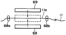
図14は、繊維束の末端部のみを、短時間で捲縮除去する方法および装置の具体例を示す概略側面図である。捲縮のかかった前駆体繊維束11の末端部11aは、繊維束保持手段68a、68bで保持され、次に前駆体繊維束保持手段68a、68bが離れる方向に移動して、捲縮のかかった繊維束の繊維束保持手段68a、68bにより挟まれた前駆体繊維束の末端部11aの捲縮を引き延ばして真っ直ぐにする。このとき、繊維束保持手段68a、68bの移動は所定の間隔となるようにしてもよいし、繊維束に負荷される張力が所定の荷重となるようにしてもよい。
【0072】
その後、繊維束の上下両面から面状ヒーター69で挟むことにより、短時間で捲縮が除去できる。具体的には、たとえば面状ヒーター69の温度80〜180℃、さらに好ましくは100〜150℃程度で、3〜10秒間程度プレスすれば充分である。
【0073】
図14に示した捲縮除去手段は、非常に簡単であるため、前述した図11、12、13の接続方法および接続装置に容易に組み込むことが可能である。
【0077】
【実施例】
以下、実施例を挙げて、本発明の内容をより具体的に説明する。
本発明による効果を確認するため、先に炭素繊維の製造工程の一実施形態として説明した製造工程中の耐炎化炉を用いて以下のような耐炎化炉走行テストを実施した。キャンに収容された前駆体繊維束は、耐炎化炉に導かれて所定の温度で、一定時間耐炎化される。キャンのある場所に次の前駆体繊維束の入ったキャンを用意し、後に詳述する糸繋ぎ方法により、キャンに収容された前駆体繊維束の末端部と次の前駆体繊維束の始端部を接続した。接続部は、ガイドバーや、ドライブステーションを通過して、熱風循環式の耐炎化炉に入る。耐炎化時間は60分とし、各水準について耐炎化炉内温度を変化させて、通糸可能な上限温度を測定し、その温度における耐炎化工程通過率を測定した。炉内温度制御の変動幅があるため、測定温度は、5℃きざみとした。
【0078】
耐炎化炉を通過した接続部は、続いて、窒素雰囲気1500℃にて炭化処理され、炭化炉通過後、ワインダーを用いてボビンに巻き上げられた。
耐炎化炉内で前駆体繊維束にかかる張力は、初期には約6kgf/st、後期には繊維束が収縮して9kgf/st程度であった。
【0079】
また、耐炎化する前駆体繊維束は、単糸デニール1.5d、フィラメント数70,000本のポリアクリル系前駆体繊維束である。この繊維束には、キャンからの立ち上げ、糸道通過を容易にするため、捲縮がかかっている。
各実施例、比較例を表1にまとめた。
【0080】
〈ブランク〉
ブランクとして、フィラメント数70,000本(70K)の前駆体繊維束自体(接続部なし)について、耐炎化炉を通過可能な上限温度と、工程通過率を測定した。結果は、耐炎化可能な上限温度が235℃であり、耐炎化温度を240℃に設定すると前駆体繊維束が焼き切れた。また、耐炎化温度235℃では、耐炎化工程、炭化工程の工程通過率は、共に100%であった。
【0081】
〈実施例1〉
フィラメント数70,000本の前駆体繊維束の末端部同士を、耐炎化糸を介在させて接続した。このとき、介在させる耐炎化糸のフィラメント数を、36,000本、48,000本、60,000本、100,000本として、4種類の接続サンプルを作製した。
【0082】
接続手段は、図14の捲縮除去手段と、図13の繊維束の接続装置を使用し、図4に示す形態となるように接続を実施した。交絡数は、図4と同様に各重ね合わせ部に4列とした。以下に手順を示す。
【0083】
(1)図14の捲縮除去手段を用いて、前駆体繊維束の末端部を捲縮除去する。(表面温度100℃〜130℃の面状ヒーターで引き延ばした状態の繊維束を両面から5秒間プレスする。)
(2)図13(a)に示すように、捲縮除去した前駆体繊維束と接続媒体である耐炎化糸を、それぞれ幅25mmに扁平状に開繊(拡幅)した後、重ね合わせて保持させる。
(3)図13(b)に示すように、各エア交絡箇所を弛ませ、各エア交絡ノズル65から圧空を噴射して、絡合処理を施す。エア交絡ノズルは、図11に示した形状であり、絡合処理空間の横幅は、50mm、隙間は6mmのものを使用した。また、ノズルから噴射される圧空の供給元での圧力は、0.5MPaとした。
(4)接続された前駆体繊維束と耐炎化糸の各末端部の余った邪魔な部分を切断除去して、接続部が図4に示す形態となるようにする。
上記の手段で作製した接続部は、エア交絡部が充分均一に混繊・絡合しており、小束でにじれるような形態の絡合は発生しなかった。
【0084】
こうして接続した前駆体繊維束の接続部を、耐炎化炉に通過させ、通過可能な上限温度を測定した。
また、同一条件による前駆体繊維束の接続部を作製し、耐炎化炉を通過可能な上限温度に設定した状態での接続部の耐炎化工程通過率、及び次の炭化工程の通過率を測定した。
その結果、表1に示す通り、ブランクと比較して、耐炎化炉の通過可能な上限温度が、同等あるいは、5℃程度低下する程度で、低下幅を非常に小さくできた。
また、耐炎化炉の温度を、通過可能な上限温度に設定して、▲1▼から▲4▼の接続部を走行させたところ、耐炎化工程、炭化工程を通過し、ワインダーによりボビンに巻き上げられた。特に、交絡部の形態が、扁平状で、均一な絡合であるため、溝付きローラーに収まり易かった。
【0085】
〈比較例1〉
フィラメント数70,000本の前駆体繊維束の末端部同士を、特公平1−12850号公報に記載の従来技術であるエア交絡方法により接続した。エア交絡ノズルは、図1に示す構造のノズルで、フィラメント数の多い繊維束用に、絡合処理室と、ノズル孔径を大きくしたものを使用した。交絡点数は、実施例1と同様に、接続する繊維束同士の重ね合わせ部を4点で交絡した。接続する束状の繊維束同士を重ねた状態で上記ノズルの絡合処理室内に配置し、ノズルに供給する圧空圧を0.5MPaとして、エア交絡処理を実施した。
上記方法によるエア交絡では、フィラメント数の多い繊維束が、幾つかの小束に分かれて、捻れるような絡合形態となった。
【0086】
作製された接続部について、実施例1と同様な方法で、耐炎化炉を通過可能な上限温度及び工程通過率を測定した。
その結果、耐炎化炉内で、捻れるように絡合したエア交絡部が蓄熱・焼損しやすく、耐炎化炉通過可能な上限温度が220℃となり、ブランクに比べて大きく低下した。また、結束力が実施例1に比べ、大幅に弱く、また、ばらつきが大きいため、220℃における耐炎化工程通過テストでは、接続部の素抜けや、破断が多発した。
【0087】
〈比較例2〉
フィラメント数70,000本の前駆体繊維束の末端部同士を、特公平1−12850号公報に記載の従来技術であるエア交絡方法により、フィラメント数60,000本の耐炎化糸を介在させて接続した。接続方法は、比較例1と同一方法とした。
上記方法によるエア交絡では、比較例1と同様に前駆体繊維束と耐炎化糸がそれぞれ、幾つかの小束に分かれて、捻れるような絡合形態となった。
【0088】
作製された接続部について、実施例1と同様な方法で、耐炎化炉を通過可能な上限温度及び工程通過率を測定した。
その結果、耐炎化炉内で、比較例1に比べると、耐炎化糸を介在させたことによる蓄熱抑制効果があり、耐炎化炉通過可能な上限温度が225℃となったが、ブランクに比べて大きく低下した。また、比較例1と同様に、結束力が実施例1に比べて大幅に弱く、また、ばらつきが大きいため、225℃における耐炎化工程通過テストでは、接続部の素抜けや、破断が多発した。
【0089】
上述した実施例1と比較例1、2から、本発明の接続方法は、従来技術に比べて、接合部の結束強度向上と接合される繊維束同士の均一な混繊及び結合、蓄熱の抑制効果を達成していることが判る。特に、実施例1の▲1▼〜▲4▼の結果から、介在させる耐炎化糸のフィラメント数Fは、前駆体繊維束のフィラメント数Gに対して、0.4×G≦F≦1.5×Gの範囲にあることが好ましく、特に、0.6×G≦F≦1.0×Gの範囲にあることが望ましい。
【0090】
〈実施例2〉
フィラメント数60,000本(60K)の耐炎化糸を介在させて、フィラメント数70,000本(70K)の前駆体繊維束の末端部同士を接続した。接続手段は、実施例1と同じで前記の(1)〜(4)の手順で実施したが、(2)の各繊維束を開繊させる幅を、25mmではなく14mmとした。
この接続方法で作製した、接続部は、実施例1の▲3▼に比べると、エア交絡部の混繊・絡合にばらつきがあった。結果は、ブランクと比較して、実施例1の▲3▼に比べると、耐炎化炉通過可能な上限温度、工程通過率とも少し低いが、比較例2に比べると、大幅に改善されている。
【0091】
実施例2では、表1に示すように、エア交絡前の各繊維束の末端部の開繊幅が、4000本/mmより大であるのに対して、実施例1、3、4では4000本/mm以下となっており各繊維束を充分に開繊した上で、絡合処理している。このことから、本発明の接続方法を、より好ましい方法で実施するためには、接続する各繊維束の末端部の開繊幅を各々4000本/mm以下となるように予め扁平状に開繊した後、重ね合わせて交絡することが望ましい。
【0095】
上記の実施例及び比較例から、本発明にかかる前駆体繊維束の接続形態は、連続的炭素繊維を工業的に製造するに際し、特にその耐炎化処理に対して、極めて効果的であることが判る。
【0096】
【表1】
【発明の効果】
以上説明したように、本発明によれば、特にフィラメント数30,000本以上の太い前駆体繊維束を流体処理により接合する場合に、接合部の結束強度向上と接続される繊維束同士の均一な混繊及び絡合、蓄熱の抑制を実現し、耐炎化工程において接続部が破断したり、焼き切れたりすることなく工程通過可能で、かつ前駆体繊維束の耐炎化処理温度に対する前駆体繊維束接続部の耐炎化処理温度の低下幅を小さくすることができ、高品質の炭素繊維を低コストで製造することができる。
【図面の簡単な説明】
【図1】従来技術である接続方法の一実施形態に係るエア交絡ノズルの斜視図である。
【図2】本発明に係る前駆体繊維束同士の接続部の概略側面図である。
【図3】接続媒体の発熱量の求め方を示す特性図である。
【図4】接続部の一例を示す概略構成図である。
【図5】接続部の別の例を示す概略構成図である。
【図6】接続部のさらに別の例を示す概略構成図である。
【図7】接続に用いるノズル装置の一例の概略構成図である。
【図8】図7に示すノズル装置による流体処理方法を示す概略図である。
【図9】ノズル本体の一例を示す透視斜視図である。
【図10】ノズル本体のさらに別の一例を示す透視斜視図である。
【図11】接続方法および接続装置の一例を示す概略斜視図である。
【図12】図11の方法および装置を用いた接続方法を示す概略側面図である。
【図13】接続装置および接続方法の別の一例を示す概略側面図である。
【図14】捲縮除去手段の一例を示す概略側面図である。
【符号の説明】
1 従来の交絡ノズル装置
2 前駆体繊維束からなる糸条
2a 前駆体繊維束の末端部
3 ノズル孔
4 処理室
10 接続媒体
11 前駆体繊維束
11a 前駆体繊維束の末端部
12、13、14 交絡部
21 交絡ノズル装置
21a 交絡ノズル上部
21b 交絡ノズル下部
22 ノズル孔
23a、23b 均圧室
31、41 交絡ノズル本体
32、42 ノズル孔
33、43 処理室
61、63、68a、68b 繊維束保持部
62a、62b 前駆体繊維束保持手段
64 接続媒体保持手段
65 交絡ノズル
65a 交絡処理室
66 リラックス保持部
69 面状ヒーター[0001]
BACKGROUND OF THE INVENTION
The present invention relates to a carbon fiber, a method for manufacturing the same, and a manufacturing apparatus, and more particularly to a technique for connecting a precursor fiber which is a carbon fiber raw yarn.
[0002]
[Prior art]
In addition to conventional aircraft and sports applications, carbon fiber has begun to be used in construction, civil engineering, and energy-related industrial applications, and demand is growing rapidly. In order to further accelerate this growth, a lower cost carbon fiber is desired. One way to reduce costs is to fire multifilament yarns at a high density to improve carbon fiber productivity. However, if the yarn density is increased, the yarn itself generates heat during the flameproofing process. Therefore, there is a problem that the oxidation reaction tends to run away. Therefore, when the yarn density is increased, in order to prevent yarn breakage due to runaway reaction, the flameproofing temperature in the flameproofing process is set to a temperature lower than the normal temperature and flameproofing is performed over a long period of time. There is a need. However, if the flame resistance temperature is greatly reduced, the flame resistance time is too long, and high yarn density firing does not lead to an improvement in productivity.
[0003]
Another problem with high yarn density firing is that runaway reactions are more likely to occur because the yarn density at the ends of the fiber bundle ends is higher than the yarn density of the fiber bundle itself. The precursor fiber bundle that is the raw yarn of the firing process is usually wound up on a bobbin, a spool or the like, or supplied in a form housed in a box, so these precursor fibers are continuously fired into carbon fibers. In order to convert, it is necessary to connect the fiber bundle terminal part of the precursor fiber wound up or accommodated in the box to the terminal part of the precursor fiber bundle before that by some means.
[0004]
As a connecting method, as described in Japanese Patent Publication No. Sho 53-23411, the precursor fiber bundles are made flame-resistant by combining them, and then the knots are cut and removed, and then re-knotted and carbonized. A method for imparting a flame resistant compound such as silicon grease to the joint described in Japanese Patent No.-50624, and both end portions of the precursor fiber bundle described in Japanese Patent Application Laid-Open No. 56-37315 are heat-treated in a special manner. There are a method of connecting and firing, a method of entanglement by high-speed fluid treatment described in JP-A-58-208420, and the like. However, in any of these methods, the yarn density at the joint portion is considerably higher than the yarn density of the fiber bundle itself.
[0005]
In Japanese Patent Publication No. 60-2407, flame-resistant yarn or carbon fiber is interposed to suppress heat storage. However, since the connection method is a knot, the knot is tightened and the yarn density is high. The heat storage suppression effect is small.
[0006]
As a method for improving these, Japanese Patent Publication No. 1-12850 discloses a method in which precursor fiber bundles or precursor fiber bundles and flameproof yarn are entangled by high-speed fluid treatment. FIG. 1 is a diagram showing an embodiment thereof. This is a method in which the end portions 2a of the fiber bundles to be joined are simply stacked in a bundle shape and placed in the processing chamber 4 of the nozzle 1, relaxed by about 5 to 60%, and then subjected to high-speed fluid processing. Further, the connection method in which the flameproof yarn is interposed has an effect that the heat storage at the connecting portion is less than the connection between the precursor fiber bundles because the flameproof yarn hardly generates heat in the flameproofing step.
[0007]
In the nozzle used in this method, as shown in FIG. 1, a high-speed jet fluid jetted from two
[0008]
However, when the number of filaments in the fiber bundle to be entangled increases, the jet fluid ejected from the nozzle does not hit the entire fiber bundle, the fiber bundle does not mix at the single yarn level, and is divided into several small bundles Get tangled. If such small bundles are entangled unevenly at the joint, a portion of the fiber bundle fibers having a high yarn density is formed, and heat is easily stored. Further, since the entanglement is weak, the bonding strength is also weakened. In each of the examples described in the above-mentioned publications, it is carried out only with a fiber bundle having a filament number of up to 12,000. By using this method, a precursor fiber bundle having a filament number of 30,000 or more is used. Even if the end portions are directly connected or connected via a flame-resistant yarn, they are broken or burnt out due to heat accumulation in the flame-proofing process for the reasons described above.
[0009]
In addition, in the case of multifilament yarns, in order to improve handling when unwinding from the accommodated state, the fiber bundles may be crimped to have a converging property. Is bulky and each single yarn is entangled little by little, so that the ends of crimped tow-like precursor fiber bundles are connected using the method of the above Japanese Patent Publication No. 1-12850. Is even more difficult. In this case, even if fiber bundles converged by crimping are overlapped and subjected to high-speed fluid treatment, the fiber bundles are not crimped at the single yarn level due to crimping, and are bulky and cottony. The movement at the single yarn level is suppressed, the fiber bundles are not sufficiently mixed, and therefore the entanglement is uneven and the bonding strength is very low.
[0010]
[Problems to be solved by the invention]
In view of the above-described problems, the present invention provides a uniform mixture of fiber bundles to be joined together with improved binding strength at the joint when thick precursor fiber bundles having 30,000 or more filaments are joined by fluid treatment. Precursor fiber entanglement and heat storage suppression, connection of the precursor fiber bundle to the flame resistant treatment temperature of the precursor fiber bundle is possible without breaking or burning out the connection part in the flame resistance process. An object of the present invention is to provide a carbon fiber production yarn, a carbon fiber, a method for producing the carbon fiber, and a production apparatus capable of reducing the reduction width of the flameproofing temperature of the part.
[0011]
[Means for Solving the Problems]
In order to solve the above problems, the carbon fiber-producing raw yarn of the present invention has the end portions of the precursor fiber bundle having a filament number of 30,000 or more,Flameproof yarnConnected through single yarn level entanglementA raw fiber for carbon fiber production, wherein the flameproofed yarn and the precursor fiber bundle are opened in a flat shape so that the ends thereof are 4,000 pieces / mm or less respectively, and then the flameproofed Connected by entanglement by fluid treatment in a state where yarn and precursor fiber bundles are overlappedIt consists of what is characterized by this.
[0012]
The flameproof yarn functions as a connection medium that is non-heat-generating at the flameproofing temperature.Here, “non-exothermic at the flameproofing temperature” means that the amount obtained by the DSC (Differential Scanning Calorimetry) method at the flameproofing temperature is 500 cal / g or less, and details will be described later.
[0013]
The end portion of the precursor fiber bundle and the connection medium are connected by, for example, entanglement by fluid processing, particularly high-speed fluid processing. Also, as a connection medium that is non-exothermic at the flameproof temperatureIn the present inventionUsing flame resistant yarnThe
[0014]
The carbon fiber according to the present invention is produced using such a raw fiber for producing carbon fiber.
[0015]
Moreover, the manufacturing method of the continuous carbon fiber which concerns on this invention WHEREIN: The terminal parts of the precursor fiber bundle whose number of filaments is 30,000 or more are put together.,Connect through flameproof yarns by tangling at the single yarn level, then fireA method for producing carbon fiber, wherein the flameproofed yarn and the precursor fiber bundle are opened in a flat shape so that the ends thereof are 4,000 pieces / mm or less, respectively, and then the flameproofed yarn is opened. And the precursor fiber bundles are overlapped and connected by fluid treatment.It consists of the method characterized by this.
[0016]
The number of filaments F of the flame resistant yarn is preferably in the range of 0.4 × G ≦ F ≦ 1.5 × G with respect to the number of filaments G of the precursor fiber bundle to be connected.
[0020]
In addition, as the precursor fiber bundle used in the present invention, both a crimped (crimped) fiber bundle and a non-crimped fiber bundle can be used.
[0021]
In addition, as the precursor fiber bundle used in the present invention, a precursor fiber bundle that is a crimped fiber bundle and that is obtained by crimping and removing only the terminal portion of the fiber bundle can be used. For example, a method of crimping and removing the end portion of the precursor fiber bundle to be entangled by heat treatment before entanglement by the fluid treatment can be used.
[0022]
Furthermore, the present invention relates toRuCarbon fiber manufacturing equipment is used to connect the ends of precursor fiber bundles together.Flameproof yarnAnd connecting the end portions of the precursor fiber bundles to each other.Flat to be 4,000 pieces / mm or lessPrecursor fiber bundle holding means for holding the fiber in an opened state;Flat end so that the end of the flame resistant yarn is 4,000 yarns / mm or lessHold in an open stateFlameproof yarnHolding means and both meansThereforeThe end of each retained precursor fiber bundle andFlameproof yarnAfter overlapping the end portions of the precursor fiber bundle andFlameproof yarnAnd a fluid processing means for performing an entanglement process by injecting a fluid onto the overlapped portion.
[0024]
In the carbon fiber manufacturing apparatus described above, in addition to the holding means for each end of the precursor fiber bundle to be connected and the fluid processing means, in addition to the part that performs fluid treatment of the precursor fiber bundle to be connected, A crimp removing means for performing a crimp removing process by heat treatment may be provided.
[0025]
By using such an apparatus, it becomes possible to produce the above-mentioned carbon fiber-producing raw yarn and further carbon fiber.
[0026]
DETAILED DESCRIPTION OF THE INVENTION
Hereinafter, preferred embodiments of the present invention will be described with reference to the drawings.
First, an embodiment of a carbon fiber production process in which the (continuous) carbon fiber production method and production apparatus according to the present invention can be suitably used will be described. Since the speed of the process for producing the precursor fiber, which is the carbon fiber-producing raw yarn, is significantly different from the speed of the firing process, the precursor fiber is usually wound on a bobbin as a fiber bundle or a box ( In the state of being folded and stacked in the can, it is supplied to the firing step. Below, the case where a precursor fiber is supplied in the state accommodated in the can is demonstrated.
[0027]
The precursor fiber bundle as the raw yarn accommodated in the can is drawn out from the can and then subjected to a flame resistance treatment in a flame resistance furnace. In this flameproofing treatment, the yarn is heat-treated at 200 to 350 ° C. in an oxidizing atmosphere to form a flameproof yarn. The flame resistant yarn is carbonized in a carbonization furnace to be carbon fiber. The carbon fiber is subjected to a surface treatment such as application of a sizing agent in the surface treatment step as necessary, and is taken up in the winding step to obtain a carbon fiber product. When the precursor fiber bundle accommodated in the can comes to the end portion, the start end portion of the precursor fiber bundle accommodated in the next can is connected. That is, the end portions of the precursor fiber bundle are connected to each other. The connected precursor fiber bundles are continuously fired to continuously produce carbon fibers. The present invention improves the method for connecting the yarns before the flameproofing process while preventing the occurrence of inconveniences in the flameproofing process, particularly in the carbon fiber production method using the yarns with a large number of thick filaments. It is.
[0028]
In particular, a precursor fiber bundle having a filament number of 30,000 or more is targeted. When the precursor fiber bundle fed out from the can comes to the end, the next can is prepared and the end portions of the precursor fiber bundle are connected to each other. Is done.
[0029]
The present inventionInThe connection method includes a method using a non-exothermic connection medium at each flame end temperature and a method of connecting each terminal directly without using a connection medium.Though conceivable, in the present invention, a method of connecting with a flame resistant yarn as a connection medium is used.
[0031]
FIG. 2 is a schematic side view showing an example of a method of connecting each end portion of the
[0032]
Here, “non-exothermic at the flameproofing temperature” means that the calorific value obtained by the DSC (Differential Scanning Calorimetry) method is 500 cal / g or less.
[0033]
The measuring method is as follows.
As shown in FIG. 3, a straight line is drawn between the point at 200 ° C. and the point at 400 ° C. of the obtained exothermic curve, and the area surrounded by the straight line and the exothermic curve is the calorific value (cal / g). To do. FIG. 3 shows an example of characteristics of the precursor raw yarn and the flameproof yarn.
[0034]
The end portions of the precursor fiber bundles are connected as follows through the non-exothermic connection medium as described above. As a desirable connection method, the precursor fiber bundle and the end portion of the flameproofing yarn are each opened in a flat shape, and then both ends of the connection medium are overlapped on each end portion of the opened precursor fiber bundle. A method of connecting by entanglement by fluid processing can be applied.
[0035]
By pre-opening and stacking the fiber bundle of the part to be subjected to fluid treatment in a flat shape, the precursor fiber bundle and the connection medium are uniformly mixed at the single yarn level at the intertwined part by fluid treatment. And can be sufficiently entangled. At this time, if the fiber bundle is not sufficiently opened, the fiber bundle may be entangled in the form of a bundle, or the fiber mixture of the precursor fiber bundle and the connection medium may be uneven. Therefore, it is desirable that the end portion of each fiber bundle is sufficiently opened in advance, and it is particularly desirable that the number of filaments be 4,000 / mm or less.
[0036]
In addition, when using a flameproof yarn as the connection medium, it is desirable to select the number of filaments of the flameproof yarn to be interposed in an appropriate range according to the properties of the precursor fiber bundle, the number of filaments, the form, the breaking strength, and the like. When the number of filaments of the precursor fiber bundle is G, the bundling force decreases as the number of filaments F of the flame resistant yarn used as the connection medium decreases with respect to the number of filaments G of the precursor fiber bundle. The connection portion may not be able to withstand the applied tension in the process, which causes a decrease in the flameproofing process passage rate. Conversely, as the number of filaments F of the flameproof yarn increases with respect to the number of filaments G of the precursor fiber bundle, the connection medium covers the precursor fiber bundle of the connection portion, and the flameproof reaction heat of the precursor fiber bundle. It becomes difficult to remove heat. As a result, the effect of suppressing heat storage in the connecting portion is in a direction of decreasing. For this reason, in the present invention, the number of filaments of the flameproof yarn intervening as the connection medium is desirably selected in an appropriate range according to the properties of the precursor fiber bundle to be connected, the number of filaments, the form, the breaking strength, etc. The number of filaments F of the flameproofing yarn intervening as the connection medium is the number of filaments G of the precursor fiber bundle,
0.4 × G ≦ F ≦ 1.5 × G
It is desirable that This is derived from examples described later.
[0037]
4 to 6 respectively show specific examples of the above connection method.
In the example shown in FIG. 4, a connection method between the end portion 11 a opened in a flat shape of the precursor fiber bundle 11 and both end portions of the
[0038]
In the example shown in FIG. 5, the end part 11a of the precursor fiber bundle 11 opened in a flat shape and the
[0039]
In the example shown in FIG. 6, the end portion 11 a of the precursor fiber bundle 11 opened in a flat shape and the
[0040]
In the example of FIGS. 4 to 6, the connection medium is disposed only on one side, but the connection medium may be configured to sandwich the end portion of the precursor fiber bundle from both sides.
[0041]
For the entanglement as shown in FIGS. 4 to 6, it is preferable to apply (high-speed) fluid treatment, and steam, water, air, etc. can be used as the jet fluid, but in terms of workability and economy In particular, a method using (high-speed) jet air is preferable. For example, an air
[0042]
As described above, in the present invention, since the nozzle structure can apply spray air evenly to the entire fiber bundle that has been opened in a flat shape in advance, even in a fiber bundle with a large number of filaments, the fiber bundle is a single yarn. It can be opened at the level and uniformly mixed / entangled.
[0043]
The air pressure supplied to the air entanglement nozzle device varies depending on the single yarn fineness, the number of filaments, the presence or absence of crimps, the state of oil adhesion, and the nozzle shape, but at least the gauge at the inlet of the air entanglement device The pressure is preferably 0.2 MPa or more and 0.4 to 0.8 MPa. If the pressure is too low, the binding force decreases due to insufficient entanglement, and if the pressure is too high, damage to the entangled portion such as single yarn breakage occurs.
[0044]
Further, by the arrangement configuration of the nozzle holes 22, the air
[0045]
As a specific structure of the nozzle, for example, a structure as shown in FIG. 9 or 10 can be adopted. In the example shown in FIG. 9, nozzle holes 32 are arranged in a row at the upper and lower portions of the nozzle body 31 so as to face each other. The precursor fiber bundle disposed in the
[0046]
In the
[0047]
In the example shown in FIG. 10, a plurality of sets of two
[0048]
The connection via the connection medium as shown in FIGS. 4 to 6 is performed using, for example, a method and apparatus as shown in FIGS.
As shown in FIG. 11, precursor fiber bundle holding means 62a and 62b having two pairs of fiber
[0049]
At this time, the end portion 11a of the precursor fiber bundle and the
[0050]
In this state, as shown in FIG. 12, the
[0051]
The connection method and the connection device shown in FIG. 13 further improve the method and the device shown in FIG. 12, and are connected by applying a plurality of rows of confounding shown in FIG. In the connection procedure, after holding each precursor fiber bundle and the connection medium as shown in FIG. 11, they are arranged so as to overlap each other as shown in FIG.
[0052]
Next, as shown in (a) of FIG. 13, air entanglement nozzles 65 are respectively installed at locations where entanglement is performed. Relax holding means 66 are installed on both sides of each
[0053]
In this method, since sufficient slack can be imparted to the fiber bundle, entanglement is easily applied and entanglement can be strengthened. Moreover, since the relaxation rate of each entanglement location can be set individually, a desirable binding form and binding strength can be obtained. In the case of the connection method shown in FIG. 4, it is desirable that the number of entanglement locations is about 3 to 5 locations in order to reduce variation in binding strength.
[0054]
In the connection method as described above, a connection medium that is non-exothermic at the flameproofing temperature is used as the connection medium, so even if the connection part is somewhat thick, the amount of heat generated during the flameproofing treatment in the flameproofing furnace. Is kept small, and inconveniences such as yarn breakage due to excessive heating are avoided. As a result, the flameproofing treatment is performed without substantially reducing the flameproofing temperature when the flameproofing treatment is performed on the connecting portions between the end portions of the thick precursor fiber bundle having a filament number of 30,000 or more. Flame resistance can be achieved without decreasing the speed (running speed of the yarn). Therefore, finally, a thick carbon fiber bundle can be continuously manufactured, and carbon fibers can be manufactured at low cost.
[0055]
In particular, the method of opening the end portion of the precursor fiber bundle and connecting it to the connection medium by entanglement by fluid treatment is the same as when the fiber bundle is tied or connected by fluid treatment according to the prior art. There is no such a problem that the bundling part is formed and the binding part is not tightened. For this reason, even if the raw yarn is a relatively thick fiber bundle, the connection portion can be held in a form with a small calorific value per unit area or unit volume, and therefore a non-heat-generating connection medium is used In combination, excessive heat generation and heat storage can be more reliably suppressed. As a result, even if it is considered that the connection portion passes through the furnace, it is not necessary to set the temperature of the flameproofing furnace so low, and the thick precursor fiber bundle is flameproofed to a predetermined state efficiently and stably. Carbon fiber can be produced at a low cost with industrially high productivity.
[0066]
Further, a method of connecting the end portion of the precursor fiber bundle described above via a connection mediumTo the lawIn this case, since the fiber bundle is preliminarily opened and then subjected to fluid treatment, even if the precursor fiber bundle to be connected is crimped, it can be connected with a certain degree of binding strength. .
[0067]
However, the crimped precursor fiber bundle is cotton-like and is entangled with single yarn, so that the fiber bundles to be connected tend to be insufficient.
[0068]
As means for solving this, in the connection method according to the present invention, crimp removal can be performed only on the terminal connection part of the crimped precursor fiber bundle.
[0069]
The term “crimp removal” as used herein is intended to reinforce entanglement by high-speed fluid treatment. It is sufficient if a short heat treatment is performed so that each single yarn is straight to some extent and the single yarn is not entangled.
[0070]
For this reason, various means such as hot air, steam, and press with a surface heater can be applied as the heat treatment means.
[0071]
FIG. 14 is a schematic side view showing a specific example of a method and apparatus for crimping and removing only the end portion of the fiber bundle in a short time. The crimped end fiber portion 11 of the precursor fiber bundle 11 is held by the fiber bundle holding means 68a, 68b, and then the precursor fiber bundle holding means 68a, 68b is moved away from the crimped portion. The crimps of the end portion 11a of the precursor fiber bundle sandwiched between the fiber bundle holding means 68a and 68b of the fiber bundle are stretched and straightened. At this time, the movement of the fiber bundle holding means 68a and 68b may be set at a predetermined interval, or the tension applied to the fiber bundle may be set at a predetermined load.
[0072]
Thereafter, the crimps can be removed in a short time by sandwiching the fiber bundle from the upper and lower surfaces with the
[0073]
The crimp removing means shown in FIG. 14 is very simple and can be easily incorporated into the connection method and the connection device shown in FIGS.
[0077]
【Example】
Hereinafter, the content of the present invention will be described more specifically with reference to examples.
In order to confirm the effect of the present invention, the following flame resistant furnace running test was performed using the flame resistant furnace in the manufacturing process described above as one embodiment of the carbon fiber manufacturing process. The precursor fiber bundle accommodated in the can is guided to a flameproofing furnace and flameproofed at a predetermined temperature for a certain time. Prepare a can containing the next precursor fiber bundle at the place where the can is, and use the yarn splicing method described in detail later to end the precursor fiber bundle contained in the can and the start end of the next precursor fiber bundle. Connected. The connecting portion passes through the guide bar and the drive station and enters the hot air circulation type flameproofing furnace. The flameproofing time was 60 minutes, the flameproofing furnace temperature was changed for each level, the upper limit temperature at which threading was possible was measured, and the flameproofing process passage rate at that temperature was measured. Because of the fluctuation range of the furnace temperature control, the measurement temperature was set to 5 ° C.
[0078]
The connection part that passed through the flameproofing furnace was subsequently carbonized in a nitrogen atmosphere at 1500 ° C., and after passing through the carbonizing furnace, it was wound up on a bobbin using a winder.
The tension applied to the precursor fiber bundle in the flameproofing furnace was about 6 kgf / st in the initial stage, and the fiber bundle contracted in the latter stage and was about 9 kgf / st.
[0079]
Moreover, the precursor fiber bundle to be flame resistant is a polyacrylic precursor fiber bundle having a single yarn denier of 1.5d and a filament number of 70,000. The fiber bundle is crimped to make it easy to start up from the can and pass through the yarn path.
Table 1 summarizes each example and comparative example.
[0080]
<blank>
As a blank, for the precursor fiber bundle itself (no connection part) having 70,000 filaments (70K), the upper limit temperature at which it can pass through the flameproofing furnace and the process pass rate were measured. As a result, the upper limit temperature at which flame resistance was possible was 235 ° C., and when the flame resistance temperature was set at 240 ° C., the precursor fiber bundle was burned out. Moreover, at the flameproofing temperature of 235 ° C., the process pass rates of the flameproofing process and the carbonizing process were both 100%.
[0081]
<Example 1>
The end portions of the precursor fiber bundle having 70,000 filaments were connected to each other with a flameproof yarn interposed therebetween. At this time, the number of filaments of the flameproofing yarn to be interposed was 36,000, 48,000, 60,000, 100,000, and four types of connection samples were produced.
[0082]
As the connecting means, the crimp removing means of FIG. 14 and the fiber bundle connecting device of FIG. 13 were used, and the connection was carried out so as to have the form shown in FIG. The number of entanglements was 4 rows in each overlapping portion as in FIG. The procedure is shown below.
[0083]
(1) Using the crimp removing means shown in FIG. 14, the end portion of the precursor fiber bundle is crimped and removed. (The fiber bundle stretched by a planar heater having a surface temperature of 100 ° C. to 130 ° C. is pressed from both sides for 5 seconds.)
(2) As shown in FIG. 13 (a), the precursor fiber bundle that has been crimped and the flame-resistant yarn that is the connection medium are each flattened (expanded) to a width of 25 mm, and then held in an overlapping manner. Let
(3) As shown in FIG. 13B, each air entangled portion is loosened, and compressed air is ejected from each air entangled
(4) Cut off and remove the remaining disturbing portions of the connected precursor fiber bundles and the respective end portions of the flameproofing yarn so that the connecting portion has the form shown in FIG.
In the connection portion produced by the above means, the air entangled portion was sufficiently uniformly mixed and entangled, and no entanglement in a form that could be blurred by a small bundle occurred.
[0084]
The connecting portion of the precursor fiber bundle thus connected was passed through a flameproofing furnace, and the upper limit temperature at which the precursor fiber bundle could pass was measured.
In addition, the precursor fiber bundle connection part under the same conditions is prepared, and the flame resistance process pass rate of the connection part in the state set to the upper limit temperature that can pass through the flame resistance furnace, and the pass rate of the next carbonization process are measured. did.
As a result, as shown in Table 1, compared with the blank, the upper limit temperature that can be passed through the flameproofing furnace was equivalent or reduced by about 5 ° C., so that the reduction range was very small.
Also, when the temperature of the flameproofing furnace was set to the upper limit temperature that can be passed and the connection part (1) to (4) was run, it passed through the flameproofing process and the carbonization process, and was wound up on the bobbin by the winder. It was. In particular, the shape of the entangled portion was flat and uniform entanglement, so it was easy to fit in the grooved roller.
[0085]
<Comparative example 1>
The end portions of the precursor fiber bundle having 70,000 filaments were connected to each other by an air entanglement method as a conventional technique described in Japanese Patent Publication No. 1-12850. As the air entanglement nozzle, a nozzle having a structure shown in FIG. 1 was used for a fiber bundle having a large number of filaments, and an entanglement processing chamber and a nozzle hole diameter increased. As for the number of entanglement points, as in Example 1, the overlapping portions of the fiber bundles to be connected were entangled at four points. The bundled fiber bundles to be connected were placed in an entanglement treatment chamber of the nozzle, and the air entanglement treatment was performed with the pneumatic pressure supplied to the nozzle being 0.5 MPa.
In the air entanglement by the above method, the fiber bundle having a large number of filaments is divided into several small bundles and is intertwined so as to be twisted.
[0086]
About the produced connection part, by the method similar to Example 1, the upper limit temperature which can pass a flame-resistant furnace, and the process passage rate were measured.
As a result, the air entangled portion entangled so as to twist in the flameproofing furnace easily stores and burns out, and the upper limit temperature at which the flameproofing furnace can pass is 220 ° C., which is significantly lower than that of the blank. Further, since the binding force was significantly weaker than that of Example 1 and the variation was large, in the test for passing through the flameproofing process at 220 ° C., the connection part was frequently omitted or ruptured frequently.
[0087]
<Comparative example 2>
The end portions of the precursor fiber bundle having 70,000 filaments are interleaved with flame-resistant yarn having 60,000 filaments by the air entanglement method which is the prior art described in JP-B-1-12850. Connected. The connection method was the same as in Comparative Example 1.
In the air entanglement by the above method, as in Comparative Example 1, the precursor fiber bundle and the flame-resistant yarn were each divided into several small bundles and were intertwined so as to be twisted.
[0088]
About the produced connection part, by the method similar to Example 1, the upper limit temperature which can pass a flame-resistant furnace, and the process passage rate were measured.
As a result, compared to Comparative Example 1 in the flameproofing furnace, there was a heat storage suppression effect due to interposing the flameproofing yarn, the upper limit temperature that can pass through the flameproofing furnace was 225 ° C, but compared to the blank Greatly decreased. Further, like the comparative example 1, the binding force is significantly weaker than that of the example 1, and the variation is large. Therefore, in the test for passing through the flameproofing process at 225 ° C., the connection part is frequently omitted or broken frequently. .
[0089]
From the above-described Example 1 and Comparative Examples 1 and 2, the connection method of the present invention improves the binding strength of the bonded portion and uniform fiber mixing and bonding between the fiber bundles to be bonded, and suppresses heat storage, as compared with the prior art. It turns out that the effect is achieved. In particular, from the results (1) to (4) of Example 1, the number of filaments F of the flameproof yarn to be interposed is 0.4 × G ≦ F ≦ 1. It is preferably in the range of 5 × G, and particularly preferably in the range of 0.6 × G ≦ F ≦ 1.0 × G.
[0090]
<Example 2>
The end portions of the precursor fiber bundle having 70,000 filaments (70K) were connected to each other by interposing flameproof yarn having 60,000 filaments (60K). The connecting means was the same as in Example 1 and was performed according to the procedures (1) to (4) described above, but the width for opening each fiber bundle in (2) was 14 mm instead of 25 mm.
Compared with (3) of Example 1, the connection part produced by this connection method had variations in the mixing / entanglement of the air entangled part. As a result, compared with the blank, the upper limit temperature at which the flameproofing furnace can pass and the process passage rate are slightly lower than those of Example 1 (3), but are significantly improved as compared with Comparative Example 2. .
[0091]
In Example 2, as shown in Table 1, the opening width of the end portion of each fiber bundle before air entanglement is larger than 4000 / mm, whereas in Examples 1, 3, and 4 it is 4000. The number of fibers / mm or less is sufficient, and each fiber bundle is sufficiently opened and then entangled. From this, in order to carry out the connecting method of the present invention in a more preferable method, the opening width of the end portion of each fiber bundle to be connected is preliminarily flattened so as to be 4000 pieces / mm or less. After that, it is desirable to overlap and entangle.
[0095]
From the above-mentioned examples and comparative examples, the connection form of the precursor fiber bundle according to the present invention is extremely effective particularly for the flameproofing treatment when industrially producing continuous carbon fibers. I understand.
[0096]
[Table 1]
【The invention's effect】
As described above, according to the present invention, particularly when a thick precursor fiber bundle having 30,000 or more filaments is joined by fluid treatment, the bundle strength of the joint is improved and the fiber bundles to be connected are uniform. Premixed fiber, entanglement, and heat storage are suppressed, and in the flameproofing process, the connecting part can be passed without breaking or burned out, and the precursor fiber with respect to the flameproofing temperature of the precursor fiber bundle The reduction width of the flameproofing treatment temperature of the bundle connection portion can be reduced, and high-quality carbon fiber can be produced at low cost.
[Brief description of the drawings]
FIG. 1 is a perspective view of an air entangled nozzle according to an embodiment of a connection method according to the prior art.
FIG. 2 is a schematic side view of a connecting portion between precursor fiber bundles according to the present invention.
FIG. 3 is a characteristic diagram showing how to determine the calorific value of the connection medium.
FIG. 4 is a schematic configuration diagram illustrating an example of a connection unit.
FIG. 5 is a schematic configuration diagram illustrating another example of a connection unit;
FIG. 6 is a schematic configuration diagram showing still another example of a connection unit.
FIG. 7 is a schematic configuration diagram of an example of a nozzle device used for connection.
8 is a schematic view showing a fluid processing method by the nozzle device shown in FIG.
FIG. 9 is a perspective view illustrating an example of a nozzle body.
FIG. 10 is a perspective view showing still another example of the nozzle body.
FIG. 11 is a schematic perspective view showing an example of a connection method and a connection device.
12 is a schematic side view showing a connection method using the method and apparatus of FIG.
FIG. 13 is a schematic side view showing another example of the connection device and the connection method.
FIG. 14 is a schematic side view showing an example of crimp removal means.
[Explanation of symbols]
1 Conventional interlacing nozzle device
2 Yarn consisting of precursor fiber bundles
2a End of precursor fiber bundle
3 Nozzle holes
4 treatment room
10 Connection medium
11 Precursor fiber bundle
11a End of precursor fiber bundle
12, 13, 14 Interlaced part
21 Entanglement nozzle device
21a Confounding nozzle top
21b Entangled nozzle lower part
22 Nozzle hole
23a, 23b Pressure equalizing chamber
31, 41 Entangled nozzle body
32, 42 Nozzle holes
33, 43 Processing chamber
61, 63, 68a, 68b Fiber bundle holder
62a, 62b Precursor fiber bundle holding means
64 Connection medium holding means
65 Entangled nozzle
65a Confounding processing room
66 Relaxing holding part
69 Surface heater
Claims (6)
Priority Applications (6)
| Application Number | Priority Date | Filing Date | Title |
|---|---|---|---|
| JP04725597A JP3722323B2 (en) | 1997-02-14 | 1997-02-14 | Carbon fiber, manufacturing method and manufacturing apparatus thereof |
| DE69825948T DE69825948T2 (en) | 1997-02-14 | 1998-02-13 | BUNDLE OF PRECURSOR CARBON FIBER, DEVICE AND METHOD FOR THE PRODUCTION THEREOF |
| PCT/JP1998/000581 WO1998036113A1 (en) | 1997-02-14 | 1998-02-13 | Precursor fiber bundle for manufacture of carbon fiber, manufacturing apparatus and method of manufacturing carbon fiber bundle |
| HU0001840A HU223804B1 (en) | 1997-02-14 | 1998-02-13 | Precursor fiber bundle for manufacture of carbon fiber, manufacturing apparatus and method of manufacturing carbon fiber bundle |
| EP98902204A EP0909842B1 (en) | 1997-02-14 | 1998-02-13 | Precursor carbon fiber bundle, apparatus and method of manufacturing thereof |
| US09/171,077 US6485592B1 (en) | 1997-02-14 | 1998-02-13 | Precursor fiber bundle for manufacture of carbon fiber, manufacturing apparatus and method of manufacturing carbon fiber bundle |
Applications Claiming Priority (1)
| Application Number | Priority Date | Filing Date | Title |
|---|---|---|---|
| JP04725597A JP3722323B2 (en) | 1997-02-14 | 1997-02-14 | Carbon fiber, manufacturing method and manufacturing apparatus thereof |
Publications (2)
| Publication Number | Publication Date |
|---|---|
| JPH10226918A JPH10226918A (en) | 1998-08-25 |
| JP3722323B2 true JP3722323B2 (en) | 2005-11-30 |
Family
ID=12770176
Family Applications (1)
| Application Number | Title | Priority Date | Filing Date |
|---|---|---|---|
| JP04725597A Expired - Lifetime JP3722323B2 (en) | 1997-02-14 | 1997-02-14 | Carbon fiber, manufacturing method and manufacturing apparatus thereof |
Country Status (6)
| Country | Link |
|---|---|
| US (1) | US6485592B1 (en) |
| EP (1) | EP0909842B1 (en) |
| JP (1) | JP3722323B2 (en) |
| DE (1) | DE69825948T2 (en) |
| HU (1) | HU223804B1 (en) |
| WO (1) | WO1998036113A1 (en) |
Families Citing this family (29)
| Publication number | Priority date | Publication date | Assignee | Title |
|---|---|---|---|---|
| JP3346358B2 (en) * | 1999-11-26 | 2002-11-18 | 株式会社豊田自動織機 | Fiber bundle, fiber bundle manufacturing method, fiber bundle joining method, and fiber bundle joining device |
| EP1420091B1 (en) * | 2001-06-12 | 2011-10-05 | Mitsubishi Rayon Co., Ltd. | Production device for carbon fibers and production method therefor |
| EP1719829B1 (en) | 2004-02-13 | 2010-07-14 | Mitsubishi Rayon Co., Ltd. | Carbon fiber precursor fiber bundle, production method and production device therefor, and carbon fiber and production method therefor |
| JP4669343B2 (en) * | 2005-08-08 | 2011-04-13 | 東邦テナックス株式会社 | Method for producing flame resistant fiber |
| DE102005051666A1 (en) * | 2005-10-28 | 2007-05-03 | Bayerische Motoren Werke Ag | Layered fiber assembly, e.g. for preparing preforms, has adjacent fiber layers intermingled when dry by locally applied air jet |
| JP5016890B2 (en) * | 2006-10-11 | 2012-09-05 | 三菱レイヨン株式会社 | Yarn splicing device and yarn splicing method |
| JP5048988B2 (en) * | 2006-10-11 | 2012-10-17 | 三菱レイヨン株式会社 | Yarn splicing device and yarn splicing method |
| JP5097377B2 (en) * | 2006-10-11 | 2012-12-12 | 三菱レイヨン株式会社 | Yarn support device and yarn support method |
| JP4796517B2 (en) * | 2007-02-02 | 2011-10-19 | 三菱レイヨン株式会社 | Carbon fiber bundle yarn manufacturing method |
| EP2275376B1 (en) * | 2008-04-18 | 2014-08-06 | Mitsubishi Rayon Co., Ltd. | Production system and production method of carbon fiber thread |
| ES2453622T3 (en) * | 2008-11-10 | 2014-04-08 | Toray Industries, Inc. | Fiber bundle with fragmented part, process for its production, and process to produce carbon fiber |
| JP5515652B2 (en) * | 2008-11-10 | 2014-06-11 | 東レ株式会社 | A method for producing a carbon fiber having a yarn splicing joint and a yarn splicing joint. |
| JP5081884B2 (en) * | 2009-09-29 | 2012-11-28 | 三菱レイヨン株式会社 | Manufacturing method of multiple carbon fiber bundle wound body |
| US9884740B2 (en) | 2009-11-09 | 2018-02-06 | Toray Industries, Inc. | Fiber bundle with pieced part, process for producing same, and process for producing carbon fiber |
| WO2011106523A1 (en) * | 2010-02-26 | 2011-09-01 | Zoltek Companies, Inc. | Spliced carbon fiber tow and method and apparatus for splicing carbon fiber tow |
| EP2868785B1 (en) * | 2012-06-27 | 2016-09-21 | Mitsubishi Rayon Co., Ltd. | Carbonization furnace for manufacturing carbon fiber bundles and method for manufacturing carbon fiber bundles |
| JP6294655B2 (en) * | 2013-12-24 | 2018-03-14 | 東邦テナックス株式会社 | Method for connecting fiber yarn and method for producing carbon fiber |
| GB2523164B (en) * | 2014-02-13 | 2019-05-01 | Gtw Developments Ltd | A fibre splicer and method for splicing fibres |
| KR101975886B1 (en) * | 2014-06-24 | 2019-05-07 | 코오롱인더스트리 주식회사 | Filament web typed precursor fabric for activated carbon fiber fabric and method of manufacturing the same |
| CN105173905B (en) * | 2015-06-15 | 2018-06-29 | 新疆溢达纺织有限公司 | Yarn connecting bonder and adhesive bonding method |
| CN105129527B (en) * | 2015-06-15 | 2018-08-17 | 广东溢达纺织有限公司 | Automatic winder Yarn connecting hardened system and method |
| CN105129525B (en) * | 2015-06-15 | 2017-11-03 | 广东溢达纺织有限公司 | Bobbin-winding machine Yarn connecting aids in bonder and its application method |
| US10570536B1 (en) | 2016-11-14 | 2020-02-25 | CFA Mills, Inc. | Filament count reduction for carbon fiber tow |
| US10385186B2 (en) * | 2016-11-28 | 2019-08-20 | Kabushiki Kaisha Toyota Chuo Kenkyusho | Carbon material precursor and method for producing carbon material using the same |
| US10604870B2 (en) * | 2018-05-31 | 2020-03-31 | Hexcel Corporation | Increasing the filament count of carbon fiber tows |
| JP7408406B2 (en) * | 2019-02-20 | 2024-01-05 | 帝人株式会社 | Method for manufacturing flame-resistant fiber bundle, method for manufacturing carbon fiber bundle, and connection device |
| CN114314196B (en) * | 2021-12-23 | 2023-05-12 | 吉林宝旌炭材料有限公司 | Online wire bonding production process and device for carbon fiber manufacturing |
| CN114606603A (en) * | 2022-03-10 | 2022-06-10 | 中国神华煤制油化工有限公司 | Carbon fiber and continuous preparation method of carbon fiber |
| CN116676693A (en) * | 2023-06-14 | 2023-09-01 | 常州市宏发纵横新材料科技股份有限公司 | Fiber air twisting device and splicing method |
Family Cites Families (23)
| Publication number | Priority date | Publication date | Assignee | Title |
|---|---|---|---|---|
| US3108028A (en) * | 1959-10-01 | 1963-10-22 | Sprunck Gerhard | Method and apparatus for the reinforcement of glass fibre webs or mats |
| US3339362A (en) * | 1966-07-05 | 1967-09-05 | Du Pont | Method of joining strands |
| US3487618A (en) * | 1967-06-28 | 1970-01-06 | Fiber Industries Inc | Yarn splicing |
| US3581486A (en) * | 1968-11-01 | 1971-06-01 | Eastman Kodak Co | Splicing of multifilament strands by turbulent gaseous fluid |
| US3945962A (en) * | 1969-09-29 | 1976-03-23 | Owens-Corning Fiberglas Corporation | Coating composition of flame retardant filler, latex binder and water soluble fire retardant borate |
| US3996325A (en) * | 1971-02-04 | 1976-12-07 | The Dow Chemical Company | Preparation of a three layer, fire retardant particleboard |
| US4048277A (en) * | 1975-12-15 | 1977-09-13 | Celanese Corporation | Splice for use during the thermal stabilization of a flat multifilament band of an acrylic fibrous material comprising at least two segments |
| JPS5323411A (en) * | 1976-08-16 | 1978-03-03 | Hitachi Ltd | Mounting structure of air intak e filter for automobile |
| JPS53147821A (en) * | 1977-05-30 | 1978-12-22 | Toray Ind Inc | Production of carbon fiber |
| JPS5450624A (en) * | 1977-09-29 | 1979-04-20 | Showa Denko Kk | Production of carbon fiber |
| JPS602407B2 (en) * | 1977-10-06 | 1985-01-21 | 昭和電工株式会社 | Continuous production method of carbon fiber |
| JPS5637315A (en) * | 1979-08-31 | 1981-04-11 | Sumitomo Chem Co Ltd | Continuous production of carbon fiber |
| JPS5846122A (en) * | 1981-09-16 | 1983-03-17 | Toray Ind Inc | Continuous process for producing carbon fiber |
| JPS5874472A (en) * | 1981-10-29 | 1983-05-04 | Murata Mach Ltd | Spun yarn ending device |
| JPS58208420A (en) * | 1982-05-26 | 1983-12-05 | Toray Ind Inc | Continuous production of carbon fiber |
| US4501037A (en) * | 1983-04-11 | 1985-02-26 | Hitco | Method for introducing heat-sensitive material into a hot environment |
| JPS602407A (en) * | 1983-06-02 | 1985-01-08 | 鈴木 允 | Triangular rice-ball packer |
| JPH0737687B2 (en) * | 1986-03-28 | 1995-04-26 | 日本石油株式会社 | Pitch-based carbon fiber manufacturing method |
| JPS6412850A (en) * | 1987-07-03 | 1989-01-17 | Amada Co Ltd | Permanent magnet type linear pulse motor |
| US4803762A (en) * | 1988-02-26 | 1989-02-14 | World Tech Fibres, Inc. | Method for splicing lengths of fiber tow |
| DE4008640A1 (en) * | 1990-03-17 | 1991-09-19 | Stahlecker Gmbh Wilhelm | SPLITTING DEVICE FOR CONNECTING THREADS |
| DE4013946A1 (en) * | 1990-04-30 | 1991-10-31 | Hoechst Ag | TWISTED MULTIFILAMENT YARN FROM HIGH MODULAR SINGLE FILAMENTS AND METHOD FOR PRODUCING SUCH A YARN |
| JPH06287832A (en) * | 1993-03-31 | 1994-10-11 | Tonen Corp | Method for interlacing fiber with air and air splicer |
-
1997
- 1997-02-14 JP JP04725597A patent/JP3722323B2/en not_active Expired - Lifetime
-
1998
- 1998-02-13 WO PCT/JP1998/000581 patent/WO1998036113A1/en active IP Right Grant
- 1998-02-13 DE DE69825948T patent/DE69825948T2/en not_active Expired - Fee Related
- 1998-02-13 US US09/171,077 patent/US6485592B1/en not_active Expired - Lifetime
- 1998-02-13 EP EP98902204A patent/EP0909842B1/en not_active Expired - Lifetime
- 1998-02-13 HU HU0001840A patent/HU223804B1/en not_active IP Right Cessation
Also Published As
| Publication number | Publication date |
|---|---|
| EP0909842A4 (en) | 1999-05-12 |
| JPH10226918A (en) | 1998-08-25 |
| HUP0001840A3 (en) | 2001-10-29 |
| DE69825948T2 (en) | 2005-09-29 |
| WO1998036113A1 (en) | 1998-08-20 |
| EP0909842A1 (en) | 1999-04-21 |
| EP0909842B1 (en) | 2004-09-01 |
| HUP0001840A2 (en) | 2000-09-28 |
| HU223804B1 (en) | 2005-01-28 |
| DE69825948D1 (en) | 2004-10-07 |
| US6485592B1 (en) | 2002-11-26 |
Similar Documents
| Publication | Publication Date | Title |
|---|---|---|
| JP3722323B2 (en) | Carbon fiber, manufacturing method and manufacturing apparatus thereof | |
| WO2010053170A1 (en) | Fiber bundle with pieced part, process for producing same, and process for producing carbon fiber | |
| JP3833654B2 (en) | Carbon fiber manufacturing apparatus and manufacturing method thereof | |
| JP4192041B2 (en) | Method and apparatus for producing carbon fiber precursor fiber bundle | |
| JP2015120582A (en) | Connection method for fiber yarn, and manufacturing method for carbon fiber | |
| JP5048988B2 (en) | Yarn splicing device and yarn splicing method | |
| JPS5846122A (en) | Continuous process for producing carbon fiber | |
| JP5016890B2 (en) | Yarn splicing device and yarn splicing method | |
| JP5515652B2 (en) | A method for producing a carbon fiber having a yarn splicing joint and a yarn splicing joint. | |
| JP5097377B2 (en) | Yarn support device and yarn support method | |
| JP5515957B2 (en) | Carbon fiber manufacturing method | |
| JP3890701B2 (en) | Continuous carbon fiber manufacturing process | |
| JP4592208B2 (en) | Method for connecting fiber yarn and method for producing carbon fiber | |
| JP2010255168A5 (en) | ||
| JPH11131348A (en) | Production of carbon fiber and device therefor | |
| JPS58208420A (en) | Continuous production of carbon fiber | |
| JP2003321160A (en) | Fiber tow package, carbon fiber using the package, and manufacturing method for chopped fiber | |
| JPH11200159A (en) | Production of carbon fiber and device therefor | |
| JP2008174846A (en) | Method for continuously producing carbon fiber | |
| JP2008144307A (en) | Method for producing carbon fiber bundle | |
| JPS6022091B2 (en) | Manufacturing method of bulky crimped fluffy yarn | |
| JP2002294517A (en) | Acrylic fiber yarn for producing carbon fiber yarn and method for producing the same | |
| JP2004076174A (en) | Method for producing carbon fiber | |
| JPS61282442A (en) | Composite yarn of synthetic fiber multifilament and spun yarn and its production | |
| JP2002038335A (en) | Method for continuous production of carbon fiber |
Legal Events
| Date | Code | Title | Description |
|---|---|---|---|
| A131 | Notification of reasons for refusal |
Free format text: JAPANESE INTERMEDIATE CODE: A131 Effective date: 20050610 |
|
| A521 | Request for written amendment filed |
Free format text: JAPANESE INTERMEDIATE CODE: A523 Effective date: 20050803 |
|
| TRDD | Decision of grant or rejection written | ||
| A01 | Written decision to grant a patent or to grant a registration (utility model) |
Free format text: JAPANESE INTERMEDIATE CODE: A01 Effective date: 20050826 |
|
| A61 | First payment of annual fees (during grant procedure) |
Free format text: JAPANESE INTERMEDIATE CODE: A61 Effective date: 20050908 |
|
| FPAY | Renewal fee payment (event date is renewal date of database) |
Free format text: PAYMENT UNTIL: 20080922 Year of fee payment: 3 |
|
| FPAY | Renewal fee payment (event date is renewal date of database) |
Free format text: PAYMENT UNTIL: 20090922 Year of fee payment: 4 |
|
| FPAY | Renewal fee payment (event date is renewal date of database) |
Free format text: PAYMENT UNTIL: 20090922 Year of fee payment: 4 |
|
| FPAY | Renewal fee payment (event date is renewal date of database) |
Free format text: PAYMENT UNTIL: 20100922 Year of fee payment: 5 |
|
| FPAY | Renewal fee payment (event date is renewal date of database) |
Free format text: PAYMENT UNTIL: 20110922 Year of fee payment: 6 |
|
| FPAY | Renewal fee payment (event date is renewal date of database) |
Free format text: PAYMENT UNTIL: 20120922 Year of fee payment: 7 |
|
| FPAY | Renewal fee payment (event date is renewal date of database) |
Free format text: PAYMENT UNTIL: 20130922 Year of fee payment: 8 |
|
| EXPY | Cancellation because of completion of term |