JP3717707B2 - Self-propelled crusher - Google Patents
Self-propelled crusher Download PDFInfo
- Publication number
- JP3717707B2 JP3717707B2 JP14388099A JP14388099A JP3717707B2 JP 3717707 B2 JP3717707 B2 JP 3717707B2 JP 14388099 A JP14388099 A JP 14388099A JP 14388099 A JP14388099 A JP 14388099A JP 3717707 B2 JP3717707 B2 JP 3717707B2
- Authority
- JP
- Japan
- Prior art keywords
- crusher
- opening
- crushed
- self
- conveyor
- Prior art date
- Legal status (The legal status is an assumption and is not a legal conclusion. Google has not performed a legal analysis and makes no representation as to the accuracy of the status listed.)
- Expired - Fee Related
Links
Images


Landscapes
- Disintegrating Or Milling (AREA)
Description
【0001】
【発明の属する技術分野】
本発明は、コンベアで破砕物を反ホッパ側に搬出する自走式破砕機に関し、更に詳しくは、例えば総重量が10トン程度でかつ破砕装置下方の空間を側方から監視することができる小型の自走式破砕機に関するものである。
【0002】
【従来の技術】
破砕機は、例えばビル解体時に搬出されるコンクリート塊や道路補修時に排出されるアスファルト塊などの建設現場で発生する大小さまざまな岩石・建設廃材、あるいは産業廃棄物、及び自然石等を、運搬する前にその作業現場で所定の大きさに破砕することにより、廃材の再利用、工事の円滑化、コスト削減等を図るものである。
【0003】
この破砕機のうち自力走行可能とした自走式破砕機は、左・右の無限軌道履帯を備えた走行体と、ホッパから投入された被破砕物を所定の大きさに破砕する破砕装置、及びホッパから投入された被破砕物を破砕装置へ導くフィーダを備えた破砕機本体と、破砕装置で破砕され小さくなった破砕物を運搬するコンベアと、このコンベアの上方に設けられコンベア上を運搬中の破砕物に含まれる磁性物を磁気的に吸引除去する磁選機とを備えている。
【0004】
このとき、前記の無限軌道履帯、破砕装置、フィーダ、コンベア、及び磁選機は、それぞれに対応する油圧駆動のアクチュエータ、すなわち左・右走行用油圧モータ、破砕用油圧モータ、フィーダ用油圧モータ、コンベア用油圧モータ、及び磁選機用油圧モータによって駆動動作される。
【0005】
ところで、近年の自走式破砕機においては、例えば特開平5−115809号公報に記載のように、油圧ショベルでホッパに被破砕物を投入するときに障害とならないように、また磁選機のメンテナンスを行う作業員が油圧ショベルの作業範囲内とならないように、コンベアを破砕機本体の後方側(反ホッパ側)に設け、破砕物を破砕機の後方側(反ホッパ側)に運搬するようになっている。
【0006】
上記構成の自走式破砕機において、破砕機上部のホッパに投入された被破砕物は、ホッパ下方のフィーダによって破砕装置へ導かれ、この破砕装置で破砕される。破砕された破砕物は、破砕装置下部の空間から破砕装置下方のコンベア上に落下し、このコンベアで反ホッパ側へ運搬される。この運搬の途中で、コンベア上方に配置された磁選機によって例えばコンクリート塊に混入している鉄筋片等を吸着して取り除く。このような動作により、破砕物は、最終的にある程度大きさが揃えられて破砕機の後部から搬出される。
【0007】
【発明が解決しようとする課題】
近年、再生資源促進法(いわゆるリサイクル法)の施行(平成3年10月)といった廃棄物再利用促進の背景の下、より小規模な建設現場等においても、積極的に自走式破砕機を導入してその現場で岩石・建設廃材や産業廃棄物等の破砕を行おうという動きが活発化している。このような動向に対応する形で、例えば10トン積みのトラック(好ましくはトレーラでない単車型のトラック)に積載し運搬可能とすることで輸送性を向上させた、以前よりも小型の(例えば総重量10トン程度の)自走式破砕機のニーズが高まっている。このようなニーズに対応すべく小型化を図る場合、破砕機本体及び走行体の小型化、特に輸送時における道路周囲構造物への干渉防止の観点から、上下方向寸法の縮小が必須となる。
【0008】
ここで、前述したように、破砕装置で破砕された破砕物は、破砕装置下方のコンベア上に落下して運搬されるようになっており、破砕装置の下端とベルトコンベア上面との間には、所定の空間が形成されている。しかし、上記のように破砕機の小型化のために上下方向寸法を図る場合には、この空間を比較的小さく縮小せざるを得ない。
【0009】
ところで、上述の廃棄物再利用促進の背景の下、近年、被破砕物として、鉄筋を含むコンクリートが増加しつつある。このようなコンクリートが破砕装置に投入されたとき、コンクリートに含まれる鉄筋が粉砕されず、破砕装置からの外力で複雑多岐に折れ曲がった形状となって破砕装置下方に排出される場合がある。このような場合は、破砕装置下部の排出口とその下方のコンベアとの間でその折れ曲がった鉄筋が滞留したり、あるいはその鉄筋がコンベア上に落下し運搬され始めた直後に付近の構造物に引っかかって滞留したりする可能性がある。もしこのような滞留が発生した場合には、すみやかに破砕装置の動作を停止し、その鉄筋の滞留(詰まり)を取り除く必要がある。
【0010】
前述のように、近年の自走式破砕機の小型化のニーズに対応して破砕装置下方の空間が縮小しているため、この鉄筋の滞留が生じる可能性が従来よりも増大する懸念が生じている。そのため、破砕作業中、この破砕装置下方の空間を常時操作者の目視により監視したいというニーズが生じている。この場合、自走式破砕機の構造上、その空間の前方からはホッパ、フィーダ、及びそれらを支持する構造物等が視界の邪魔になり、後方からはコンベア、磁選機、及びそれらを支持する構造物等が視界の邪魔になるため、側方から監視を行うのが好ましい。
【0011】
しかしながら、従来提唱されている小型化を図った自走式破砕機においては、このようなニーズに配慮されておらず、破砕装置下方の空間を側方から監視することはできなかった。
【0012】
本発明は、上記の事柄に鑑みてなされたものであり、その目的は、コンベアで破砕物を反ホッパ側に搬出する小型の自走式破砕機において、破砕装置下方の空間を側方から監視することができる構成を提供することにある。
【0013】
【課題を解決するための手段】
本発明は上記の目的を達成するために、第1の発明は、被破砕物を破砕装置によって破砕し、破砕後の破砕物を搬出コンベアによって排出する小型の自走式破砕機において、破砕機取付け部とこの破砕機取付け部の下方に一体構造として設けられた脚部とを備えたトラックフレームと、前記脚部の下部にそれぞれ設けた無限軌道履帯と、最下部が前記無限軌道履帯と同程度の高さに位置するように吊下部材で前記脚部間に配設した搬出コンベアと、前記脚部の側面における前記破砕装置下部に対応する部分に設けられ、前記破砕装置から前記搬出コンベアに受け入れられる破砕物の挙動を目視するための開口部と、この開口部から流出する粉塵を抑えるように前記開口部の上部に一端が設けられためくりあげることができる開閉手段とを備えたことを特徴とする。
【0014】
また、第2の発明は、第1の発明において、前記開閉手段は、ゴムであることを特徴とする。
【0015】
更に、第3の発明は、第1の発明において、前記開閉手段は、ゴムであることを特徴とする。
【0021】
【発明の実施の形態】
以下、本発明の自走式破砕機の一実施の形態を図面を用いて説明する。
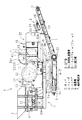
図1は、本実施の形態の自走式破砕機の全体構造を表す側面図であり、図2は、図1に示した自走式破砕機の上面図であり、図3は、図1中III−III断面による断面図である。
【0022】
これら図1〜図3において、自走式破砕機1は、近年の廃棄物再利用促進の背景に基づく小型化のニーズに対応し、例えば総重量が10トン程度になっており、10トン積みのトラック(好ましくはトレーラでない単車型のトラック)に積載し運搬可能で輸送性を向上させたものとなっている。
【0023】
この自走式破砕機1は、例えば油圧ショベルのバケット等の作業具により被破砕物が投入され、その被破砕物を受け入れるホッパ2、側断面形状が略V字形をなすとともに、ホッパ2に受け入れた被破砕物を所定の大きさに破砕し下方へ排出する破砕装置、例えばジョークラッシャ3、及びホッパ2に受け入れた被破砕物をジョークラッシャ3へと搬送し導くフィーダ4を備えた破砕機本体7と、ジョークラッシャ3で破砕され下方へ排出された破砕物を受け入れて破砕機1の後方側(図1及び図2中右側)に運搬し搬出するコンベア5と、このコンベア5の上方に設けられコンベア5上を運搬中の破砕物に含まれる磁性物を磁気的に吸引除去する磁選機6と、前記の破砕機本体7の下方に設けられた走行体8とを有する。
【0024】
走行体8は、破砕機取付け部9A及びこの破砕機取付け部9Aの下方に溶接一体構造として設けられた脚部9Bとを備えたトラックフレーム9と、前記の脚部9Bの下部に設けた左・右の無限軌道履帯8aとを備えている。またこのとき、トラックフレーム9の短手方向(破砕機の幅方向)に配設された脚部9Bの両側面9B1,9B2のうち、側面9B1には、内部を覗くことができる開口部50が形成されている。
【0025】
ホッパ2及びフィーダ4は、トラックフレーム9の長手方向前方側(詳細には、破砕機取付け部9Aの長手方向前方側、すなわち図1及び図2中左側)に搭載され、詳細にはそのトラックフレーム破砕機取付け部9Aの長手方向前方側端部の上方に搭載されている。
【0026】
ジョークラッシャ3は、ホッパ2及びフィーダ4よりも後方側(図1及び図2中右側)に位置しており、図1及び図2に示すように、トラックフレーム9の長手方向(図1及び図2中左右方向)中間部上に搭載されている。このとき、クラッシャ用油圧モータ10で発生した駆動力をベルト11を介してフライホイール12に伝達し、さらにフライホイール12に伝達された駆動力を公知の変換機構で動歯3a(図2参照)の揺動運動に変換し、この動歯3aを固定歯3b(同)に対して前後に揺動させることにより、フィーダ4より供給された被破砕物を所定の大きさに破砕するようになっている。また、このジョークラッシャ3の上方及び側方はハウジング13に覆われているが、ハウジング13の上側部分には開閉可能なカバー14が設けられ、これを開くことにより図2に示すように上方(直上方及び側方側・前後方向側上方を含む)からジョークラッシャ3内部を視認できるようになっている。
【0027】
フィーダ4は、図1及び図2に示すように、トラックフレーム9の長手方向(図1及び図2中左右方向)前方側(図1及び図2中左側)端部に支柱16aを介して設けたフィーダフレーム16上に搭載されており、その略直上にホッパ2が位置している。このフィーダ4は、いわゆるグリズリフィーダと称されるものであり、フィーダ用油圧モータ15で発生した駆動力によって、ホッパ2からの被破砕物を載置する複数枚(この例では2枚)の鋸歯状プレート4aを含む底板部を加振する。これによってホッパ2に投入された被破砕物を順次ジョークラッシャ3に搬送供給する(=搬送機能)とともに、その搬送中において被破砕物に付着した細かい土砂等を鋸歯状プレート4aの鋸歯の隙間から下方に落下させるようになっている。すなわち、鋸歯状プレート4aの鋸歯の隙間の大きさよりも小さな粒度の被破砕物をふるい落とすことにより、上記隙間の大きさ以上の粒度の被破砕物を選別するという選別機能も併せて備えている。
【0028】
コンベア5は、図1に示すように、搬送側(破砕機後方側、図1中右側)部分が支持部材5dを介し後述のパワーユニット32に吊り下げ支持されている。また、反搬送側(破砕機前方側、図1中左側)部分は、トラックフレーム破砕機取付け部9Aよりも下方に位置し、支持部材5b,5cを介し、トラックフレーム破砕機取付け部9Aから吊り下げられるように支持されている。このコンベア5は、コンベア用油圧モータ17によってベルト5aを駆動し、これによってジョークラッシャ3からベルト5a上に落下してきた破砕物を運搬するようになっている。
【0029】
磁選機6は、支持部材6bを介し、前述のパワーユニット32に取り付けられており、前記のコンベアベルト5aの上方にこのコンベアベルト5aと略直交するように配置された磁選機ベルト6aを、磁選機用油圧モータ18によって磁力発生手段(図示せず)まわりに駆動することにより、磁力発生手段からの磁力をベルト6a越しに作用させて磁性物をベルト6aに吸着させた後、コンベアベルト5aと略直交する方向に運搬してそのコンベアベルト5aの側方に落下させるようになっている。
【0030】
無限軌道履帯8aはそれぞれ、走行体8に設けられた駆動輪19とアイドラ20との間に掛け渡されており、駆動輪19に設けられた走行用油圧モータ21(図示せず)によって駆動力が与えられることにより破砕機1を走行させるようになっている。
【0031】
トラックフレーム9の破砕機取付け部9Aの長手方向後方側(図1,図2中右側)端部の上部には、パワーユニット32の基礎下部構造をなすパワーユニットフレーム32aを搭載している(図1参照)。
【0032】
このパワーユニット32は、前記のクラッシャ用油圧モータ10、フィーダ用油圧モータ15、コンベア用油圧モータ17、磁選機用油圧モータ18、左・右走行用油圧モータ21等の油圧アクチュエータへの圧油を吐出する少なくとも1つの油圧ポンプ(図示せず)と、この油圧ポンプを駆動する原動機としてのエンジン(同)と、前記油圧ポンプから前記油圧アクチュエータへ供給される圧油の方向・流量をそれぞれ制御する複数のコントロールバルブ(同)を備えたコントロールバルブ装置(同)と、前記エンジンの燃料タンク(図2にその給油口34のみ図示)と、作動油タンク(図2にその給油口35のみ図示)とを内蔵している。
【0033】
このパワーユニット32において、エンジンカバー36の下方にあるエンジンを起動すると、上記のように油圧ポンプが駆動される。その一方、その駆動力によって、エンジンの冷却風(後述する)上流側に設けたファン(図示せず)が回転し、外部の空気が吸気孔37からパワーユニット32内部空間に導入され、冷却風となってラジエータ(図2にその冷却水点検口38を示す)を冷却した後、ファンに流入する。さらにファンから吹き出された冷却風は、エンジン、マフラ(図示せず)、油圧ポンプ等を冷却した後、排気孔39から大気放出される。またこのとき、エンジンからの排気ガスは、エンジンの排気マニホールド(図示せず)からマフラに流入して消音された後、マフラに接続された排気ガス管40から大気中に放出される。なお41は、エンジンへの吸入空気を清浄化するエアクリーナの吸入口である。
【0034】
また、パワーユニット32の前方側(図2中左側)には、操作者が搭乗する運転席42が併設されており、操作者がこの運転席42に立つ(図1参照)ことにより、破砕作業中においてフィーダ4による被破砕物の供給状況やジョークラッシャ3による破砕状況を監視することができるようになっている。なお、前記のトラックフレーム破砕機取付け部9Aには、前記運転席42への乗り降りのための足場となる補助ステップ9Aaが取り付けられている。
【0035】
ここで、上記ジョークラッシャ3、フィーダ4、コンベア5、磁選機6、及び無限軌道履帯8aは、上記クラッシャ用油圧モータ10、フィーダ用油圧モータ15、コンベア用油圧モータ17、磁選機用油圧モータ18、及び走行用油圧モータ21を含む、公知の油圧駆動装置によって駆動される。
【0036】
すなわち、例えば自走式破砕機1を自走させる時には、前記の油圧ポンプからの圧油が、運転席42の操作レバー52,53の操作に応じて切り換えられるコントロールバルブ装置内の走行用コントロールバルブ(図示せず)を介し走行用油圧モータ21に供給され、これによって無限軌道履帯8aが駆動されて走行体8が走行する。
【0037】
また、破砕作業時には、例えば運転席42に設けた操作盤(図示せず)のフィーダ起動スイッチ(同)、クラッシャ起動スイッチ(同)、及びコンベア・磁選機起動スイッチ(同)が順次押されることで、その操作信号が制御盤150(図2参照)内のコントローラ(同)に入力され、さらにコントローラから駆動信号として出力されてフィーダ用コントロールバルブ(同)、破砕用コントロールバルブ(同)、及びコンベア・磁選機用コントロールバルブ(同)が切り換えられ、これによって前記の油圧ポンプからの圧油がこれらのコントロールバルブを介し対応する油圧モータ15,10,17,18に供給され、これによってフィーダ4、ジョークラッシャ3、コンベア5及び磁選機6が駆動される。
【0038】
なお、以上において、無限軌道履帯8aが走行手段を構成し、ジョークラッシャ3が破砕装置を構成し、トラックフレーム9がフレームを構成し、トラックフレーム側面9B1が、フレームの短手方向に配設された側面を構成し、開口部50がその側面に設けられた開口を構成する。
【0039】
図1、図2中左右方向が、フレームの長手方向に相当し、図1,図2中左側がフレームの長手方向一の側に相当し、図1,図2中右側がフレームの長手方向他の側に相当する。また、図3中左右方向が、フレームの短手方向に相当する。
【0040】
次に、本実施の形態の動作を以下に説明する。
【0041】
例えば油圧ショベルのバケットでホッパ2に被破砕物を投入すると、その投入された被破砕物が、フィーダ4において所定粒度以上のもののみが選別されつつジョークラッシャ3へと導かれ、ジョークラッシャ3で所定の大きさに破砕される。破砕された破砕物は、ジョークラッシャ3下方の空間から排出された後、コンベア5上に落下し受け入れられて反ホッパ2側へ運搬され、その運搬途中で磁選機6によって破砕物に混入した磁性物(例えばコンクリートの建設廃材に混入している鉄筋片等)が取り除かれ、大きさがほぼ揃えられて、最終的に破砕機1の後部(図1中右端部)から搬出される。
【0042】
ところで、上述の廃棄物再利用促進の背景の下、近年、被破砕物として鉄筋を含むコンクリートが増加しつつあり、上記の動作中においてこのようなコンクリートがジョークラッシャ3に投入されたとき、コンクリートに含まれる鉄筋が粉砕されず、ジョークラッシャ3からの外力で複雑多岐に折れ曲がった形状となってジョークラッシャ3の下方に排出される場合がある。このような場合は、ジョークラッシャ3下部の排出口とその下方のコンベア5との間でその折れ曲がった鉄筋が滞留したり、あるいはその鉄筋がコンベア5上に落下し運搬され始めた直後に付近の構造物に引っかかって滞留したりする可能性がある。もしこのような滞留が発生した場合には、すみやかにジョークラッシャ3の動作を停止し、その鉄筋の滞留(詰まり)を取り除く必要がある。
【0043】
ここで、本実施の形態による自走式破砕機1は、破砕機全体の小型化を図った通常のこの種の小型自走式破砕機と同様、特に明確な図示を省略するが、ジョークラッシャ3下方の空間が比較的小さく縮小されており、これによって破砕機全体の上下方向寸法の縮小を実現している。そのため、上記の鉄筋の滞留が生じる可能性が従来よりも増大する懸念がないとは言えない。
【0044】
このとき、前述のようにジョークラッシャ3はトラックフレーム破砕機取付け部9A上に載置されており、またコンベア5は図1に示すように吊下部材5b,5cを介してトラックフレーム破砕機取付け部9Aに吊り下げ支持され、走行体8と同程度の高さに位置している。そこで、本実施の形態においては、トラックフレーム脚部9Bの側面9B1に開口部50を設ける。これにより、ジョークラッシャ3下方の空間における破砕物の挙動、すなわちジョークラッシャ3下方から排出されコンベア5に受け入れられ運搬されるときの様子を、破砕機1の側方から目視することができる。したがって、破砕作業中、操作者の目視によって破砕装置下方空間を常時監視できるので、上記の滞留が生じた場合にもすみやかに対応することができる。
【0045】
さらに、前述のように破砕機1全体の小型化のためにジョークラッシャ3下方の空間が縮小されているため、小型でない従来機のように作業員がその空間に侵入しメンテナンス作業を行うのは困難となるが、上記開口部50を設けることにより、この開口部50を通じて側方よりメンテナンス作業を容易に行うことができる。
【0046】
なお、上記本発明の一実施の形態においては、開口部50をトラックフレーム両側面8b1,8b2のうち一方の側面8b1に設けたが、これに限られず、反対側の側面8b2に設けても良いし、さらに両方に設けても良いことは言うまでもない。要は、ジョークラッシャ3下方から排出されコンベア5に受け入れられ運搬されるときの様子が最もよく視認できる位置に開口部50を設ければ足りる。
【0047】
また、上記本発明の一実施の形態においては、トラックフレーム側面8b1に設けた開口部50をそのまま露出させていたが、これに限られず、別途設けた部材でこの開口部50を露出しないようにしても良い。そのような変形例を以下に示す。
【0048】
▲1▼開閉扉を設けたもの
すなわち、要部拡大側面図を図4に示すように、開口部50を開閉可能な開閉手段として開口部50とほぼ同じ大きさの開閉扉48を取り付けたものである。
【0049】
このとき、開閉扉48は、2枚の板状部材48a,48bと2つのヒンジ48c,48dを備えている。ヒンジ48cは、板状部材48aをトラックフレーム側面8b1に回動可能に接続するものであり、板状部材48a,48bを上方へ持ち上げるように回動させることができる。一方、ヒンジ48dは、板状部材48aと板状部材48bとを回動可能に接続するものであり、上記のようにヒンジ48cを介して板状部材48a,48bを上方へ持ち上げていくときに、板状部材48aと板状部材48bとを山折りに折り曲げることができるようになっている。これにより、無限軌道履帯8aに接触することなく円滑に開閉動作できるように図られている。このような接触の可能性が低い場合には板状部材48a,48bをまとめて1枚のプレート状としても良いことは言うまでもない。
【0050】
本変形例によれば、以下のような効果を奏する。
すなわち、ジョークラッシャ3下方の空間には、ジョークラッシャ3で破砕された破砕物が落下してくるため、破砕作業中は細かく砕かれた破砕物の破片が塵埃となって舞っている場合が多いが、必要に応じて適宜開閉扉48で開口部50を閉じることにより、この塵埃が破砕機外へ流出してくるのを防止することができる。
【0051】
▲2▼透明プレートで覆ったもの
すなわち、要部拡大側面図を図5に示すように、開口部50を覆うように、例えばアクリル、プラスチック、ガラス等の透過性部材で製作された透明プレート49を設けたものである。プレート49の上端部はヒンジ49aを介しトラックフレーム側面8b1に回動可能に接続されており、これによって、開口部50を開閉可能となっている。すなわち、透明プレート49が開口部50を開閉可能な開閉手段を構成する。
【0052】
この場合、プレート49は透明であることにより、開口部50を覆ったまま(閉じたまま)の状態でもジョークラッシャ3下方空間を監視することができるという効果がある。
【0053】
なお、上記のようにプレートではなく、ビニールや透明なゴム等を用いて開閉手段としても良い。この場合、ビニールやゴムは柔らかく容易にめくり上げることができるので、ヒンジを設けることなく単純に上端部をトラックフレーム側面8b1に固定しても良い。また、透明プレートで上記▲1▼で述べたような折り戸構造を構成してもよい。
【0054】
なお、本発明は、以上のように小型の自走式破砕機にその適用対象が限定されるものではなく、いわゆる中型や大型の自走式破砕機に適用してもよい。
【0055】
また、以上においては、原動機として、エンジンを備えた自走式破砕機に適用した場合を例にとって説明したが、これに限られず、例えば原動機として電動モータ等を備えた自走式破砕機に適用してもよい。
【0056】
また、以上においては、破砕装置として動歯3aと固定歯3bとで破砕を行うジョークラッシャ3を備えた自走式破砕機1を例にとって説明したが、これに限られず、他の破砕装置、例えば、ロール状の回転体に破砕用の刃を取り付けたものを一対としてそれら一対を互いに逆方向へ回転させ、それら回転体の間に被破砕物を挟み込んで破砕を行う回転式破砕装置(いわゆるロールクラッシャを含む6軸破砕機等)や、平行に配置された軸にカッタを備え、互いに逆回転させることにより被破砕物をせん断する破砕装置(いわゆるシュレッダを含む2軸せん断機等)を備えた破砕機にも適用可能である。これらの場合には、フィーダ4を省略しても良い。これらの場合にも同様の効果を得る。
【0057】
さらに、以上においては、フィーダ4として、油圧モータの駆動力を用いて、被破砕物を載置する複数枚の鋸歯状プレート4aを含む底板部を加振するグリズリフィーダを備えた自走式破砕機1を例にとって説明したが、これに限られない。すなわち、他のタイプのフィーダ、例えば、ホッパから投入された被破砕物をホッパ下方に設けた略平板形状の底板に載置し、この底板を油圧モータで発生した駆動力に基づきベース駆動機構によって略水平方向に往復運動させることにより、後続の破砕原料の投入によって先行の破砕原料を底板上で順次押し出し、底板の前端から破砕原料を破砕装置へと順次供給するいわゆるプレートフィーダを備えた破砕機にも適用可能である。
【0058】
また、以上においては、破砕装置による破砕作業に関連する作業を行う補助機械として、フィーダ4、コンベア5、及び磁選機6を備えた自走式破砕機に適用した場合を例にとって説明したが、これに限られない。すなわち、フィーダ4、コンベア5、及び磁選機6のうち、いくつかを適宜省略した自走式破砕機、例えばフィーダ4がなくホッパ2からダクトやシュートを介し直接ジョークラッシャ3に被破砕物を供給するものや、作業事情に応じ磁選機6が省略されているものに対し適用しても良い。逆に、フィーダ4、コンベア5、及び磁選機6に加え、さらに追加の補助機械、例えば、コンベア5の路程を長くするためにコンベア5の下流側(又は上流側)に位置する補助コンベア(2次コンベア)や、破砕物の粒度に応じさらなる選別を行うためにジョークラッシャ3の下流側に位置する振動スクリーンを設けた自走式破砕機に適用しても良い。
【0059】
【発明の効果】
本発明によれば、フレームの短手方向に配設された側面に開口を設けるので、破砕装置下方の空間を側方から目視で監視することができる。
【図面の簡単な説明】
【図1】本発明の一実施の形態による自走式破砕機の全体構造を表す側面図である。
【図2】図1に示した自走式破砕機の上面図である。
【図3】図1中III−III断面から見た断面図である。
【図4】図1に示した開口部に開閉扉を設けた変形例を示す要部拡大側面図である。
【図5】図1に示した開口部を透明プレートで覆った変形例を示す要部拡大側面図である。
【符号の説明】
2 ホッパ
3 ジョークラッシャ(破砕装置)
4 フィーダ
5 コンベア
6 磁選機
7 破砕機本体
8 走行体
8a 無限軌道履帯(走行手段)
9 トラックフレーム(フレーム)
9A 破砕機取付け部
9B 脚部
9B1 側面
32 パワーユニット
48 開閉扉(開閉手段)
49 透明プレート(開閉手段)
50 開口部(開口)[0001]
BACKGROUND OF THE INVENTION
The present invention relates to a self-propelled crusher that carries a crushed material to a non-hopper side by a conveyor. More specifically, for example, the total weight is about 10 tons and a small space capable of monitoring a space below a crushing device from the side. This is related to the self-propelled crusher.
[0002]
[Prior art]
The crusher transports various types of rocks, construction waste materials, industrial waste, natural stones, etc. generated at construction sites, such as concrete lumps delivered at the time of building demolition and asphalt lumps discharged at road repair By crushing to a predetermined size at the work site before, reuse of waste materials, smooth construction, cost reduction, etc. are intended.
[0003]
Among the crushers, the self-propelled crusher that can run on its own is a traveling body equipped with left and right endless track tracks, a crushing device that crushes the object to be crushed into a predetermined size from a hopper, And a crusher body equipped with a feeder for guiding the material to be crushed from the hopper to the crushing device, a conveyor for conveying the crushed material that has been crushed and reduced by the crushing device, and transported on the conveyor provided above this conveyor A magnetic separator for magnetically removing magnetic substances contained in the crushed material.
[0004]
At this time, the endless track crawler, the crushing device, the feeder, the conveyor, and the magnetic separator are respectively hydraulically driven actuators, that is, a left / right traveling hydraulic motor, a crushing hydraulic motor, a feeder hydraulic motor, and a conveyor. It is driven by a hydraulic motor for magnetic field and a hydraulic motor for magnetic separator.
[0005]
By the way, in recent self-propelled crushers, as described in, for example, Japanese Patent Laid-Open No. 5-115809, maintenance of the magnetic separator is performed so as not to become an obstacle when a material to be crushed is put into a hopper with a hydraulic excavator. In order to prevent the worker who performs the excavator from being within the working range of the excavator, the conveyor is provided on the rear side (on the opposite hopper side) of the crusher body, and the crushed material is transported to the rear side (on the opposite hopper side) of the crusher. It has become.
[0006]
In the self-propelled crusher having the above-described configuration, the material to be crushed put into the hopper above the crusher is guided to the crushing device by the feeder below the hopper, and is crushed by this crushing device. The crushed crushed material falls from the space below the crushing device onto a conveyor below the crushing device, and is conveyed to the non-hopper side by this conveyor. In the middle of this transportation, for example, a reinforcing bar piece mixed in a concrete lump is adsorbed and removed by a magnetic separator arranged above the conveyor. By such an operation, the crushed material is finally arranged to some extent in size and carried out from the rear part of the crusher.
[0007]
[Problems to be solved by the invention]
In recent years, with the background of promoting waste reuse such as the enforcement of the Recycling Resource Promotion Law (so-called Recycling Law) (October 1991), we have actively used self-propelled crushers even at smaller construction sites. There is a growing movement to crush rocks, construction wastes, industrial waste, etc. at the site. In response to these trends, for example, a 10-ton truck (preferably a single-truck truck that is not a trailer) can be loaded and transported to improve transportability. There is a growing need for self-propelled crushers (about 10 tons in weight). In order to reduce the size in order to meet such needs, it is essential to reduce the size in the vertical direction from the viewpoint of reducing the size of the crusher main body and the traveling body, in particular, preventing interference with road surrounding structures during transportation.
[0008]
Here, as described above, the crushed material crushed by the crushing device falls and is transported on the conveyor below the crushing device, and between the lower end of the crushing device and the upper surface of the belt conveyor. A predetermined space is formed. However, in the case where the vertical dimension is intended to reduce the size of the crusher as described above, this space must be reduced to a relatively small size.
[0009]
By the way, in the background of the above-mentioned waste recycling promotion, in recent years, concrete containing reinforcing bars is increasing as objects to be crushed. When such concrete is thrown into the crushing device, the reinforcing bars contained in the concrete may not be crushed but may be discharged into the lower part of the crushing device in a complicated and bent shape due to external force from the crushing device. In such a case, the bent reinforcing bar stays between the discharge port at the lower part of the crushing device and the conveyor below it, or immediately after the reinforcing bar falls on the conveyor and starts to be transported to the nearby structure. There is a possibility of getting stuck. If such stagnation occurs, it is necessary to immediately stop the operation of the crushing device and remove the stagnation (clogging) of the reinforcing bars.
[0010]
As described above, since the space below the crushing device has been reduced in response to the recent needs for downsizing of self-propelled crushers, there is a concern that the possibility of the stay of this reinforcing bar will increase more than before. ing. For this reason, during the crushing operation, there is a need to constantly monitor the space below the crushing device with the visual observation of the operator. In this case, on the structure of the self-propelled crusher, from the front of the space, the hopper, feeder, and the structure that supports them obstruct the view, and from the rear, the conveyor, magnetic separator, and support them. Since structures and the like obstruct the field of view, it is preferable to monitor from the side.
[0011]
However, in the conventional self-propelled crusher proposed for miniaturization, such a need is not taken into consideration, and the space below the crushing device cannot be monitored from the side.
[0012]
The present invention has been made in view of the above-mentioned matters, and its purpose is to monitor the space below the crushing device from the side in a small self-propelled crusher that carries the crushed material to the non-hopper side by a conveyor. It is to provide a configuration that can be done.
[0013]
[Means for Solving the Problems]
For the present invention to achieve the above object, a first aspect of the present invention is crushed by crusher to be crushed, in a small self-propelled crushing machine for discharging the crushed crushed by unloading conveyor, broken mill A track frame having an attachment portion and a leg portion provided as an integrated structure below the crusher attachment portion, an endless track crawler provided at a lower portion of the leg portion, and a lowermost portion the same as the endless track crawler A carry-out conveyor disposed between the legs by a suspension member so as to be positioned at a certain height, and a part corresponding to a lower part of the crushing device on a side surface of the leg, and from the crushing device to the carry-out conveyor An opening for visually observing the behavior of the crushed material received by the opening, and an opening / closing means provided with one end at the top of the opening so as to suppress dust flowing out from the opening. It is characterized in.
[0014]
According to a second aspect, in the first aspect, the opening / closing means is rubber.
[0015]
Furthermore, a third invention is characterized in that, in the first invention, the opening / closing means is rubber.
[0021]
DETAILED DESCRIPTION OF THE INVENTION
Hereinafter, an embodiment of the self-propelled crusher of the present invention will be described with reference to the drawings.
FIG. 1 is a side view showing the entire structure of the self-propelled crusher of the present embodiment, FIG. 2 is a top view of the self-propelled crusher shown in FIG. 1, and FIG. It is sectional drawing by a middle III-III cross section.
[0022]
1 to 3, the self-propelled crusher 1 responds to the need for downsizing based on the recent background of waste recycling promotion, for example, the total weight is about 10 tons, It can be loaded and transported on this type of truck (preferably a single-truck type truck that is not a trailer) to improve transportability.
[0023]
The self-propelled crusher 1 has a
[0024]
The traveling
[0025]
The
[0026]
The
[0027]
As shown in FIGS. 1 and 2, the
[0028]
As shown in FIG. 1, the
[0029]
The
[0030]
The endless
[0031]
A power unit frame 32a that forms the basic lower structure of the
[0032]
The
[0033]
In this
[0034]
Further, a driver's
[0035]
Here, the
[0036]
That is, for example, when the self-propelled crusher 1 is self-propelled, the pressure oil from the hydraulic pump is switched according to the operation of the operation levers 52 and 53 of the driver's
[0037]
Further, at the time of crushing work, for example, a feeder start switch (same), a crusher start switch (same), and a conveyor / magnetic separator start switch (same) of an operation panel (not shown) provided in the driver's
[0038]
In the above description, the
[0039]
The left and right directions in FIGS. 1 and 2 correspond to the longitudinal direction of the frame, the left side in FIGS. 1 and 2 corresponds to one side in the longitudinal direction of the frame, and the right side in FIGS. It corresponds to the side. Further, the left-right direction in FIG. 3 corresponds to the short direction of the frame.
[0040]
Next, the operation of the present embodiment will be described below.
[0041]
For example, when a material to be crushed is introduced into the
[0042]
By the way, in the background of the above-mentioned waste recycling promotion, in recent years, concrete containing reinforcing bars has been increasing as a material to be crushed, and when such concrete is thrown into the
[0043]
Here, the self-propelled crusher 1 according to the present embodiment is not particularly clearly illustrated, as is the case with a normal small-sized self-propelled crusher of this type that is intended to reduce the size of the entire crusher, but the jaw crusher. 3 The space below is reduced to a relatively small size, thereby reducing the vertical dimension of the entire crusher. Therefore, it cannot be said that there is no concern that the possibility that the above-mentioned rebar stays will increase compared to the conventional case.
[0044]
At this time, as described above, the
[0045]
Further, as described above, the space below the
[0046]
In the embodiment of the present invention, the
[0047]
In the embodiment of the present invention, the
[0048]
(1) A door provided with an opening / closing door, that is, an enlarged side view of the main part, as shown in FIG. 4, with an opening / closing
[0049]
At this time, the open /
[0050]
According to this modification, the following effects can be obtained.
In other words, since the crushed material crushed by the
[0051]
(2) What is covered with a transparent plate, that is, a
[0052]
In this case, since the
[0053]
Note that the opening / closing means may be made of vinyl, transparent rubber or the like instead of the plate as described above. In this case, since vinyl and rubber are soft and can be easily turned up, the upper end may be simply fixed to the track frame side surface 8b1 without providing a hinge. Further, the folding door structure as described in the above item (1) may be formed of a transparent plate.
[0054]
Note that the present invention is not limited to a small self-propelled crusher as described above, and may be applied to a so-called medium or large self-propelled crusher.
[0055]
In the above description, the case where the motor is applied to a self-propelled crusher equipped with an engine has been described as an example. However, the present invention is not limited to this. For example, the motor is applied to a self-propelled crusher equipped with an electric motor or the like. May be.
[0056]
Moreover, in the above, although demonstrated as an example the self-propelled crusher 1 provided with the
[0057]
Furthermore, in the above, the self-propelled crushing provided with the grizzly feeder as the
[0058]
Moreover, in the above, although demonstrated as an example the case where it applied to the self-propelled crusher provided with the
[0059]
【The invention's effect】
According to the present invention, since the opening is provided on the side surface arranged in the short direction of the frame, the space below the crushing device can be visually monitored from the side.
[Brief description of the drawings]
FIG. 1 is a side view showing the overall structure of a self-propelled crusher according to an embodiment of the present invention.
FIG. 2 is a top view of the self-propelled crusher shown in FIG.
FIG. 3 is a cross-sectional view taken along the line III-III in FIG.
4 is an enlarged side view of an essential part showing a modification in which an opening / closing door is provided in the opening shown in FIG. 1. FIG.
5 is an enlarged side view of an essential part showing a modification in which the opening shown in FIG. 1 is covered with a transparent plate. FIG.
[Explanation of symbols]
2
4
9 Track frame (frame)
9A Crusher mounting part 9B Leg part 9B1 Side face 32
49 Transparent plate (opening / closing means)
50 opening (opening)
Claims (3)
Priority Applications (1)
| Application Number | Priority Date | Filing Date | Title |
|---|---|---|---|
| JP14388099A JP3717707B2 (en) | 1999-05-24 | 1999-05-24 | Self-propelled crusher |
Applications Claiming Priority (1)
| Application Number | Priority Date | Filing Date | Title |
|---|---|---|---|
| JP14388099A JP3717707B2 (en) | 1999-05-24 | 1999-05-24 | Self-propelled crusher |
Publications (3)
| Publication Number | Publication Date |
|---|---|
| JP2000325820A JP2000325820A (en) | 2000-11-28 |
| JP2000325820A5 JP2000325820A5 (en) | 2004-08-12 |
| JP3717707B2 true JP3717707B2 (en) | 2005-11-16 |
Family
ID=15349176
Family Applications (1)
| Application Number | Title | Priority Date | Filing Date |
|---|---|---|---|
| JP14388099A Expired - Fee Related JP3717707B2 (en) | 1999-05-24 | 1999-05-24 | Self-propelled crusher |
Country Status (1)
| Country | Link |
|---|---|
| JP (1) | JP3717707B2 (en) |
Families Citing this family (3)
| Publication number | Priority date | Publication date | Assignee | Title |
|---|---|---|---|---|
| JP2003047883A (en) * | 2001-08-03 | 2003-02-18 | Komatsu Ltd | Crusher |
| JP4031357B2 (en) * | 2002-11-28 | 2008-01-09 | 株式会社小松製作所 | Self-propelled crusher |
| JP2009000031A (en) * | 2007-06-20 | 2009-01-08 | Matsuyama Plow Mfg Co Ltd | Harvester |
-
1999
- 1999-05-24 JP JP14388099A patent/JP3717707B2/en not_active Expired - Fee Related
Also Published As
| Publication number | Publication date |
|---|---|
| JP2000325820A (en) | 2000-11-28 |
Similar Documents
| Publication | Publication Date | Title |
|---|---|---|
| JP2004174376A (en) | Crushing system and crushing method | |
| JP3717707B2 (en) | Self-propelled crusher | |
| JP4031357B2 (en) | Self-propelled crusher | |
| JP3761045B2 (en) | Mobile crusher with two-axis shear type crusher | |
| JP3709301B2 (en) | Self-propelled crusher | |
| JP2000202808A (en) | Self-propelled branch/leaf/trunk crushing machine | |
| JP2012135743A (en) | Jaw crusher | |
| JPH11197535A (en) | Mobile crusher | |
| JP2006281126A (en) | Self-propelled treating machine and self-propelled conveyer | |
| JP3840359B2 (en) | Self-propelled crusher | |
| JP2542486B2 (en) | Especially, a continuous jaw crusher for crushing stone debris at construction sites. | |
| JP2004230330A (en) | Self-traveling crusher and sorting/ transporting apparatus used for the same | |
| JP5031385B2 (en) | Recycling machine and self-propelled crusher | |
| JP3696752B2 (en) | Self-propelled crusher | |
| JP4088506B2 (en) | Self-propelled recycling machine | |
| JP4206744B2 (en) | Self-propelled crusher | |
| JP2000325826A (en) | Crawler crushing machine | |
| JP2000325821A (en) | Crawler crushing machine | |
| JP2001321690A (en) | Self-traveling crusher and method for operating self- traveling crusher | |
| JP2004081954A (en) | Self-propelled crusher | |
| JP3887617B2 (en) | Self-propelled crusher | |
| JP2004000993A (en) | Self-propelled type crusher | |
| JP3705918B2 (en) | Crushing machine | |
| JP2004174458A (en) | Self-propelling crusher | |
| JP2001190980A (en) | Self-propelled crusher |
Legal Events
| Date | Code | Title | Description |
|---|---|---|---|
| A977 | Report on retrieval |
Free format text: JAPANESE INTERMEDIATE CODE: A971007 Effective date: 20050117 |
|
| A131 | Notification of reasons for refusal |
Free format text: JAPANESE INTERMEDIATE CODE: A131 Effective date: 20050208 |
|
| A521 | Written amendment |
Free format text: JAPANESE INTERMEDIATE CODE: A523 Effective date: 20050405 |
|
| A131 | Notification of reasons for refusal |
Free format text: JAPANESE INTERMEDIATE CODE: A131 Effective date: 20050510 |
|
| A521 | Written amendment |
Free format text: JAPANESE INTERMEDIATE CODE: A523 Effective date: 20050613 |
|
| A131 | Notification of reasons for refusal |
Free format text: JAPANESE INTERMEDIATE CODE: A131 Effective date: 20050712 |
|
| A521 | Written amendment |
Free format text: JAPANESE INTERMEDIATE CODE: A523 Effective date: 20050802 |
|
| TRDD | Decision of grant or rejection written | ||
| A01 | Written decision to grant a patent or to grant a registration (utility model) |
Free format text: JAPANESE INTERMEDIATE CODE: A01 Effective date: 20050830 |
|
| A61 | First payment of annual fees (during grant procedure) |
Free format text: JAPANESE INTERMEDIATE CODE: A61 Effective date: 20050831 |
|
| R150 | Certificate of patent or registration of utility model |
Free format text: JAPANESE INTERMEDIATE CODE: R150 |
|
| FPAY | Renewal fee payment (event date is renewal date of database) |
Free format text: PAYMENT UNTIL: 20080909 Year of fee payment: 3 |
|
| FPAY | Renewal fee payment (event date is renewal date of database) |
Free format text: PAYMENT UNTIL: 20090909 Year of fee payment: 4 |
|
| FPAY | Renewal fee payment (event date is renewal date of database) |
Free format text: PAYMENT UNTIL: 20100909 Year of fee payment: 5 |
|
| FPAY | Renewal fee payment (event date is renewal date of database) |
Free format text: PAYMENT UNTIL: 20100909 Year of fee payment: 5 |
|
| FPAY | Renewal fee payment (event date is renewal date of database) |
Free format text: PAYMENT UNTIL: 20110909 Year of fee payment: 6 |
|
| FPAY | Renewal fee payment (event date is renewal date of database) |
Free format text: PAYMENT UNTIL: 20110909 Year of fee payment: 6 |
|
| FPAY | Renewal fee payment (event date is renewal date of database) |
Free format text: PAYMENT UNTIL: 20120909 Year of fee payment: 7 |
|
| FPAY | Renewal fee payment (event date is renewal date of database) |
Free format text: PAYMENT UNTIL: 20120909 Year of fee payment: 7 |
|
| FPAY | Renewal fee payment (event date is renewal date of database) |
Free format text: PAYMENT UNTIL: 20130909 Year of fee payment: 8 |
|
| LAPS | Cancellation because of no payment of annual fees |