JP3708784B2 - Hybrid vehicle transmission unit - Google Patents
Hybrid vehicle transmission unit Download PDFInfo
- Publication number
- JP3708784B2 JP3708784B2 JP2000079548A JP2000079548A JP3708784B2 JP 3708784 B2 JP3708784 B2 JP 3708784B2 JP 2000079548 A JP2000079548 A JP 2000079548A JP 2000079548 A JP2000079548 A JP 2000079548A JP 3708784 B2 JP3708784 B2 JP 3708784B2
- Authority
- JP
- Japan
- Prior art keywords
- housing
- motor
- transmission
- chamber
- partition
- Prior art date
- Legal status (The legal status is an assumption and is not a legal conclusion. Google has not performed a legal analysis and makes no representation as to the accuracy of the status listed.)
- Expired - Fee Related
Links
Images


Classifications
-
- B—PERFORMING OPERATIONS; TRANSPORTING
- B60—VEHICLES IN GENERAL
- B60K—ARRANGEMENT OR MOUNTING OF PROPULSION UNITS OR OF TRANSMISSIONS IN VEHICLES; ARRANGEMENT OR MOUNTING OF PLURAL DIVERSE PRIME-MOVERS IN VEHICLES; AUXILIARY DRIVES FOR VEHICLES; INSTRUMENTATION OR DASHBOARDS FOR VEHICLES; ARRANGEMENTS IN CONNECTION WITH COOLING, AIR INTAKE, GAS EXHAUST OR FUEL SUPPLY OF PROPULSION UNITS IN VEHICLES
- B60K6/00—Arrangement or mounting of plural diverse prime-movers for mutual or common propulsion, e.g. hybrid propulsion systems comprising electric motors and internal combustion engines ; Control systems therefor, i.e. systems controlling two or more prime movers, or controlling one of these prime movers and any of the transmission, drive or drive units Informative references: mechanical gearings with secondary electric drive F16H3/72; arrangements for handling mechanical energy structurally associated with the dynamo-electric machine H02K7/00; machines comprising structurally interrelated motor and generator parts H02K51/00; dynamo-electric machines not otherwise provided for in H02K see H02K99/00
- B60K6/20—Arrangement or mounting of plural diverse prime-movers for mutual or common propulsion, e.g. hybrid propulsion systems comprising electric motors and internal combustion engines ; Control systems therefor, i.e. systems controlling two or more prime movers, or controlling one of these prime movers and any of the transmission, drive or drive units Informative references: mechanical gearings with secondary electric drive F16H3/72; arrangements for handling mechanical energy structurally associated with the dynamo-electric machine H02K7/00; machines comprising structurally interrelated motor and generator parts H02K51/00; dynamo-electric machines not otherwise provided for in H02K see H02K99/00 the prime-movers consisting of electric motors and internal combustion engines, e.g. HEVs
- B60K6/22—Arrangement or mounting of plural diverse prime-movers for mutual or common propulsion, e.g. hybrid propulsion systems comprising electric motors and internal combustion engines ; Control systems therefor, i.e. systems controlling two or more prime movers, or controlling one of these prime movers and any of the transmission, drive or drive units Informative references: mechanical gearings with secondary electric drive F16H3/72; arrangements for handling mechanical energy structurally associated with the dynamo-electric machine H02K7/00; machines comprising structurally interrelated motor and generator parts H02K51/00; dynamo-electric machines not otherwise provided for in H02K see H02K99/00 the prime-movers consisting of electric motors and internal combustion engines, e.g. HEVs characterised by apparatus, components or means specially adapted for HEVs
- B60K6/38—Arrangement or mounting of plural diverse prime-movers for mutual or common propulsion, e.g. hybrid propulsion systems comprising electric motors and internal combustion engines ; Control systems therefor, i.e. systems controlling two or more prime movers, or controlling one of these prime movers and any of the transmission, drive or drive units Informative references: mechanical gearings with secondary electric drive F16H3/72; arrangements for handling mechanical energy structurally associated with the dynamo-electric machine H02K7/00; machines comprising structurally interrelated motor and generator parts H02K51/00; dynamo-electric machines not otherwise provided for in H02K see H02K99/00 the prime-movers consisting of electric motors and internal combustion engines, e.g. HEVs characterised by apparatus, components or means specially adapted for HEVs characterised by the driveline clutches
- B60K6/387—Actuated clutches, i.e. clutches engaged or disengaged by electric, hydraulic or mechanical actuating means
-
- B—PERFORMING OPERATIONS; TRANSPORTING
- B60—VEHICLES IN GENERAL
- B60K—ARRANGEMENT OR MOUNTING OF PROPULSION UNITS OR OF TRANSMISSIONS IN VEHICLES; ARRANGEMENT OR MOUNTING OF PLURAL DIVERSE PRIME-MOVERS IN VEHICLES; AUXILIARY DRIVES FOR VEHICLES; INSTRUMENTATION OR DASHBOARDS FOR VEHICLES; ARRANGEMENTS IN CONNECTION WITH COOLING, AIR INTAKE, GAS EXHAUST OR FUEL SUPPLY OF PROPULSION UNITS IN VEHICLES
- B60K6/00—Arrangement or mounting of plural diverse prime-movers for mutual or common propulsion, e.g. hybrid propulsion systems comprising electric motors and internal combustion engines ; Control systems therefor, i.e. systems controlling two or more prime movers, or controlling one of these prime movers and any of the transmission, drive or drive units Informative references: mechanical gearings with secondary electric drive F16H3/72; arrangements for handling mechanical energy structurally associated with the dynamo-electric machine H02K7/00; machines comprising structurally interrelated motor and generator parts H02K51/00; dynamo-electric machines not otherwise provided for in H02K see H02K99/00
- B60K6/20—Arrangement or mounting of plural diverse prime-movers for mutual or common propulsion, e.g. hybrid propulsion systems comprising electric motors and internal combustion engines ; Control systems therefor, i.e. systems controlling two or more prime movers, or controlling one of these prime movers and any of the transmission, drive or drive units Informative references: mechanical gearings with secondary electric drive F16H3/72; arrangements for handling mechanical energy structurally associated with the dynamo-electric machine H02K7/00; machines comprising structurally interrelated motor and generator parts H02K51/00; dynamo-electric machines not otherwise provided for in H02K see H02K99/00 the prime-movers consisting of electric motors and internal combustion engines, e.g. HEVs
- B60K6/22—Arrangement or mounting of plural diverse prime-movers for mutual or common propulsion, e.g. hybrid propulsion systems comprising electric motors and internal combustion engines ; Control systems therefor, i.e. systems controlling two or more prime movers, or controlling one of these prime movers and any of the transmission, drive or drive units Informative references: mechanical gearings with secondary electric drive F16H3/72; arrangements for handling mechanical energy structurally associated with the dynamo-electric machine H02K7/00; machines comprising structurally interrelated motor and generator parts H02K51/00; dynamo-electric machines not otherwise provided for in H02K see H02K99/00 the prime-movers consisting of electric motors and internal combustion engines, e.g. HEVs characterised by apparatus, components or means specially adapted for HEVs
- B60K6/40—Arrangement or mounting of plural diverse prime-movers for mutual or common propulsion, e.g. hybrid propulsion systems comprising electric motors and internal combustion engines ; Control systems therefor, i.e. systems controlling two or more prime movers, or controlling one of these prime movers and any of the transmission, drive or drive units Informative references: mechanical gearings with secondary electric drive F16H3/72; arrangements for handling mechanical energy structurally associated with the dynamo-electric machine H02K7/00; machines comprising structurally interrelated motor and generator parts H02K51/00; dynamo-electric machines not otherwise provided for in H02K see H02K99/00 the prime-movers consisting of electric motors and internal combustion engines, e.g. HEVs characterised by apparatus, components or means specially adapted for HEVs characterised by the assembly or relative disposition of components
- B60K6/405—Housings
-
- B—PERFORMING OPERATIONS; TRANSPORTING
- B60—VEHICLES IN GENERAL
- B60K—ARRANGEMENT OR MOUNTING OF PROPULSION UNITS OR OF TRANSMISSIONS IN VEHICLES; ARRANGEMENT OR MOUNTING OF PLURAL DIVERSE PRIME-MOVERS IN VEHICLES; AUXILIARY DRIVES FOR VEHICLES; INSTRUMENTATION OR DASHBOARDS FOR VEHICLES; ARRANGEMENTS IN CONNECTION WITH COOLING, AIR INTAKE, GAS EXHAUST OR FUEL SUPPLY OF PROPULSION UNITS IN VEHICLES
- B60K6/00—Arrangement or mounting of plural diverse prime-movers for mutual or common propulsion, e.g. hybrid propulsion systems comprising electric motors and internal combustion engines ; Control systems therefor, i.e. systems controlling two or more prime movers, or controlling one of these prime movers and any of the transmission, drive or drive units Informative references: mechanical gearings with secondary electric drive F16H3/72; arrangements for handling mechanical energy structurally associated with the dynamo-electric machine H02K7/00; machines comprising structurally interrelated motor and generator parts H02K51/00; dynamo-electric machines not otherwise provided for in H02K see H02K99/00
- B60K6/20—Arrangement or mounting of plural diverse prime-movers for mutual or common propulsion, e.g. hybrid propulsion systems comprising electric motors and internal combustion engines ; Control systems therefor, i.e. systems controlling two or more prime movers, or controlling one of these prime movers and any of the transmission, drive or drive units Informative references: mechanical gearings with secondary electric drive F16H3/72; arrangements for handling mechanical energy structurally associated with the dynamo-electric machine H02K7/00; machines comprising structurally interrelated motor and generator parts H02K51/00; dynamo-electric machines not otherwise provided for in H02K see H02K99/00 the prime-movers consisting of electric motors and internal combustion engines, e.g. HEVs
- B60K6/42—Arrangement or mounting of plural diverse prime-movers for mutual or common propulsion, e.g. hybrid propulsion systems comprising electric motors and internal combustion engines ; Control systems therefor, i.e. systems controlling two or more prime movers, or controlling one of these prime movers and any of the transmission, drive or drive units Informative references: mechanical gearings with secondary electric drive F16H3/72; arrangements for handling mechanical energy structurally associated with the dynamo-electric machine H02K7/00; machines comprising structurally interrelated motor and generator parts H02K51/00; dynamo-electric machines not otherwise provided for in H02K see H02K99/00 the prime-movers consisting of electric motors and internal combustion engines, e.g. HEVs characterised by the architecture of the hybrid electric vehicle
- B60K6/48—Parallel type
-
- B—PERFORMING OPERATIONS; TRANSPORTING
- B60—VEHICLES IN GENERAL
- B60K—ARRANGEMENT OR MOUNTING OF PROPULSION UNITS OR OF TRANSMISSIONS IN VEHICLES; ARRANGEMENT OR MOUNTING OF PLURAL DIVERSE PRIME-MOVERS IN VEHICLES; AUXILIARY DRIVES FOR VEHICLES; INSTRUMENTATION OR DASHBOARDS FOR VEHICLES; ARRANGEMENTS IN CONNECTION WITH COOLING, AIR INTAKE, GAS EXHAUST OR FUEL SUPPLY OF PROPULSION UNITS IN VEHICLES
- B60K6/00—Arrangement or mounting of plural diverse prime-movers for mutual or common propulsion, e.g. hybrid propulsion systems comprising electric motors and internal combustion engines ; Control systems therefor, i.e. systems controlling two or more prime movers, or controlling one of these prime movers and any of the transmission, drive or drive units Informative references: mechanical gearings with secondary electric drive F16H3/72; arrangements for handling mechanical energy structurally associated with the dynamo-electric machine H02K7/00; machines comprising structurally interrelated motor and generator parts H02K51/00; dynamo-electric machines not otherwise provided for in H02K see H02K99/00
- B60K6/20—Arrangement or mounting of plural diverse prime-movers for mutual or common propulsion, e.g. hybrid propulsion systems comprising electric motors and internal combustion engines ; Control systems therefor, i.e. systems controlling two or more prime movers, or controlling one of these prime movers and any of the transmission, drive or drive units Informative references: mechanical gearings with secondary electric drive F16H3/72; arrangements for handling mechanical energy structurally associated with the dynamo-electric machine H02K7/00; machines comprising structurally interrelated motor and generator parts H02K51/00; dynamo-electric machines not otherwise provided for in H02K see H02K99/00 the prime-movers consisting of electric motors and internal combustion engines, e.g. HEVs
- B60K6/50—Architecture of the driveline characterised by arrangement or kind of transmission units
- B60K6/54—Transmission for changing ratio
- B60K6/543—Transmission for changing ratio the transmission being a continuously variable transmission
-
- F—MECHANICAL ENGINEERING; LIGHTING; HEATING; WEAPONS; BLASTING
- F16—ENGINEERING ELEMENTS AND UNITS; GENERAL MEASURES FOR PRODUCING AND MAINTAINING EFFECTIVE FUNCTIONING OF MACHINES OR INSTALLATIONS; THERMAL INSULATION IN GENERAL
- F16H—GEARING
- F16H57/00—General details of gearing
- F16H57/02—Gearboxes; Mounting gearing therein
- F16H57/029—Gearboxes; Mounting gearing therein characterised by means for sealing the gearboxes, e.g. to improve airtightness
-
- F—MECHANICAL ENGINEERING; LIGHTING; HEATING; WEAPONS; BLASTING
- F16—ENGINEERING ELEMENTS AND UNITS; GENERAL MEASURES FOR PRODUCING AND MAINTAINING EFFECTIVE FUNCTIONING OF MACHINES OR INSTALLATIONS; THERMAL INSULATION IN GENERAL
- F16H—GEARING
- F16H57/00—General details of gearing
- F16H57/02—Gearboxes; Mounting gearing therein
- F16H57/037—Gearboxes for accommodating differential gearings
-
- F—MECHANICAL ENGINEERING; LIGHTING; HEATING; WEAPONS; BLASTING
- F16—ENGINEERING ELEMENTS AND UNITS; GENERAL MEASURES FOR PRODUCING AND MAINTAINING EFFECTIVE FUNCTIONING OF MACHINES OR INSTALLATIONS; THERMAL INSULATION IN GENERAL
- F16H—GEARING
- F16H57/00—General details of gearing
- F16H57/04—Features relating to lubrication or cooling or heating
- F16H57/042—Guidance of lubricant
- F16H57/0421—Guidance of lubricant on or within the casing, e.g. shields or baffles for collecting lubricant, tubes, pipes, grooves, channels or the like
-
- F—MECHANICAL ENGINEERING; LIGHTING; HEATING; WEAPONS; BLASTING
- F16—ENGINEERING ELEMENTS AND UNITS; GENERAL MEASURES FOR PRODUCING AND MAINTAINING EFFECTIVE FUNCTIONING OF MACHINES OR INSTALLATIONS; THERMAL INSULATION IN GENERAL
- F16H—GEARING
- F16H57/00—General details of gearing
- F16H57/04—Features relating to lubrication or cooling or heating
- F16H57/048—Type of gearings to be lubricated, cooled or heated
- F16H57/0487—Friction gearings
- F16H57/0489—Friction gearings with endless flexible members, e.g. belt CVTs
-
- F—MECHANICAL ENGINEERING; LIGHTING; HEATING; WEAPONS; BLASTING
- F16—ENGINEERING ELEMENTS AND UNITS; GENERAL MEASURES FOR PRODUCING AND MAINTAINING EFFECTIVE FUNCTIONING OF MACHINES OR INSTALLATIONS; THERMAL INSULATION IN GENERAL
- F16H—GEARING
- F16H57/00—General details of gearing
- F16H57/02—Gearboxes; Mounting gearing therein
- F16H2057/02013—Extension units for gearboxes, e.g. additional units attached to a main gear
-
- F—MECHANICAL ENGINEERING; LIGHTING; HEATING; WEAPONS; BLASTING
- F16—ENGINEERING ELEMENTS AND UNITS; GENERAL MEASURES FOR PRODUCING AND MAINTAINING EFFECTIVE FUNCTIONING OF MACHINES OR INSTALLATIONS; THERMAL INSULATION IN GENERAL
- F16H—GEARING
- F16H57/00—General details of gearing
- F16H57/02—Gearboxes; Mounting gearing therein
- F16H2057/02034—Gearboxes combined or connected with electric machines
-
- F—MECHANICAL ENGINEERING; LIGHTING; HEATING; WEAPONS; BLASTING
- F16—ENGINEERING ELEMENTS AND UNITS; GENERAL MEASURES FOR PRODUCING AND MAINTAINING EFFECTIVE FUNCTIONING OF MACHINES OR INSTALLATIONS; THERMAL INSULATION IN GENERAL
- F16H—GEARING
- F16H57/00—General details of gearing
- F16H57/02—Gearboxes; Mounting gearing therein
- F16H2057/02039—Gearboxes for particular applications
- F16H2057/02043—Gearboxes for particular applications for vehicle transmissions
-
- F—MECHANICAL ENGINEERING; LIGHTING; HEATING; WEAPONS; BLASTING
- F16—ENGINEERING ELEMENTS AND UNITS; GENERAL MEASURES FOR PRODUCING AND MAINTAINING EFFECTIVE FUNCTIONING OF MACHINES OR INSTALLATIONS; THERMAL INSULATION IN GENERAL
- F16H—GEARING
- F16H57/00—General details of gearing
- F16H57/02—Gearboxes; Mounting gearing therein
- F16H2057/02095—Measures for reducing number of parts or components
-
- F—MECHANICAL ENGINEERING; LIGHTING; HEATING; WEAPONS; BLASTING
- F16—ENGINEERING ELEMENTS AND UNITS; GENERAL MEASURES FOR PRODUCING AND MAINTAINING EFFECTIVE FUNCTIONING OF MACHINES OR INSTALLATIONS; THERMAL INSULATION IN GENERAL
- F16H—GEARING
- F16H61/00—Control functions within control units of change-speed- or reversing-gearings for conveying rotary motion ; Control of exclusively fluid gearing, friction gearing, gearings with endless flexible members or other particular types of gearing
- F16H61/66—Control functions within control units of change-speed- or reversing-gearings for conveying rotary motion ; Control of exclusively fluid gearing, friction gearing, gearings with endless flexible members or other particular types of gearing specially adapted for continuously variable gearings
- F16H61/662—Control functions within control units of change-speed- or reversing-gearings for conveying rotary motion ; Control of exclusively fluid gearing, friction gearing, gearings with endless flexible members or other particular types of gearing specially adapted for continuously variable gearings with endless flexible members
-
- Y—GENERAL TAGGING OF NEW TECHNOLOGICAL DEVELOPMENTS; GENERAL TAGGING OF CROSS-SECTIONAL TECHNOLOGIES SPANNING OVER SEVERAL SECTIONS OF THE IPC; TECHNICAL SUBJECTS COVERED BY FORMER USPC CROSS-REFERENCE ART COLLECTIONS [XRACs] AND DIGESTS
- Y02—TECHNOLOGIES OR APPLICATIONS FOR MITIGATION OR ADAPTATION AGAINST CLIMATE CHANGE
- Y02T—CLIMATE CHANGE MITIGATION TECHNOLOGIES RELATED TO TRANSPORTATION
- Y02T10/00—Road transport of goods or passengers
- Y02T10/60—Other road transportation technologies with climate change mitigation effect
- Y02T10/62—Hybrid vehicles
-
- Y—GENERAL TAGGING OF NEW TECHNOLOGICAL DEVELOPMENTS; GENERAL TAGGING OF CROSS-SECTIONAL TECHNOLOGIES SPANNING OVER SEVERAL SECTIONS OF THE IPC; TECHNICAL SUBJECTS COVERED BY FORMER USPC CROSS-REFERENCE ART COLLECTIONS [XRACs] AND DIGESTS
- Y10—TECHNICAL SUBJECTS COVERED BY FORMER USPC
- Y10S—TECHNICAL SUBJECTS COVERED BY FORMER USPC CROSS-REFERENCE ART COLLECTIONS [XRACs] AND DIGESTS
- Y10S903/00—Hybrid electric vehicles, HEVS
- Y10S903/902—Prime movers comprising electrical and internal combustion motors
- Y10S903/903—Prime movers comprising electrical and internal combustion motors having energy storing means, e.g. battery, capacitor
- Y10S903/904—Component specially adapted for hev
- Y10S903/912—Drive line clutch
- Y10S903/914—Actuated, e.g. engaged or disengaged by electrical, hydraulic or mechanical means
-
- Y—GENERAL TAGGING OF NEW TECHNOLOGICAL DEVELOPMENTS; GENERAL TAGGING OF CROSS-SECTIONAL TECHNOLOGIES SPANNING OVER SEVERAL SECTIONS OF THE IPC; TECHNICAL SUBJECTS COVERED BY FORMER USPC CROSS-REFERENCE ART COLLECTIONS [XRACs] AND DIGESTS
- Y10—TECHNICAL SUBJECTS COVERED BY FORMER USPC
- Y10S—TECHNICAL SUBJECTS COVERED BY FORMER USPC CROSS-REFERENCE ART COLLECTIONS [XRACs] AND DIGESTS
- Y10S903/00—Hybrid electric vehicles, HEVS
- Y10S903/902—Prime movers comprising electrical and internal combustion motors
- Y10S903/903—Prime movers comprising electrical and internal combustion motors having energy storing means, e.g. battery, capacitor
- Y10S903/904—Component specially adapted for hev
- Y10S903/915—Specific drive or transmission adapted for hev
- Y10S903/917—Specific drive or transmission adapted for hev with transmission for changing gear ratio
- Y10S903/918—Continuously variable
-
- Y—GENERAL TAGGING OF NEW TECHNOLOGICAL DEVELOPMENTS; GENERAL TAGGING OF CROSS-SECTIONAL TECHNOLOGIES SPANNING OVER SEVERAL SECTIONS OF THE IPC; TECHNICAL SUBJECTS COVERED BY FORMER USPC CROSS-REFERENCE ART COLLECTIONS [XRACs] AND DIGESTS
- Y10—TECHNICAL SUBJECTS COVERED BY FORMER USPC
- Y10S—TECHNICAL SUBJECTS COVERED BY FORMER USPC CROSS-REFERENCE ART COLLECTIONS [XRACs] AND DIGESTS
- Y10S903/00—Hybrid electric vehicles, HEVS
- Y10S903/902—Prime movers comprising electrical and internal combustion motors
- Y10S903/903—Prime movers comprising electrical and internal combustion motors having energy storing means, e.g. battery, capacitor
- Y10S903/952—Housing details
-
- Y—GENERAL TAGGING OF NEW TECHNOLOGICAL DEVELOPMENTS; GENERAL TAGGING OF CROSS-SECTIONAL TECHNOLOGIES SPANNING OVER SEVERAL SECTIONS OF THE IPC; TECHNICAL SUBJECTS COVERED BY FORMER USPC CROSS-REFERENCE ART COLLECTIONS [XRACs] AND DIGESTS
- Y10—TECHNICAL SUBJECTS COVERED BY FORMER USPC
- Y10T—TECHNICAL SUBJECTS COVERED BY FORMER US CLASSIFICATION
- Y10T74/00—Machine element or mechanism
- Y10T74/21—Elements
- Y10T74/2186—Gear casings
Description
【0001】
【発明の属する技術分野】
本発明は、エンジンと、発電機を兼ねるモータとを有し、これらの出力トルクを変速装置に伝達することにより、エンジンおよびモータのいずれか一方又は双方で走行駆動力を得るようにしたハイブリッド車両に搭載される変速機ユニットに関する。
【0002】
【従来の技術】
従来、変速機ユニットのハウジング構造において、例えば実開平2−62157号公報に記載の技術が知られている。これは、図5(イ)に示すように、ケースaとケースbから構成され、ケースaとケースbの合わせ面cのフランジ構造が図5(ロ)に示すように、ケースの外周のみで接合されているものである。
【0003】
【発明が解決しようとする課題】
しかしながら、上述の従来技術においては、以下のような問題を有していた。すなわち、モータを内蔵したハイブリッド車両の変速機ユニットを構成する場合、ケース内にモータ室を構成しなければならない。しかしながら、モータ室はドライ(オイル等が潤滑していない状態)に保つ必要があり、変速機等が収装されたウエット室とのシール性を保つことが困難であった。
また、モータハウジングを別途変速機ユニットハウジングに備えることで、モータ室をドライ室として画成することが考えられるが、部品点数の増加を招くという問題があった。
【0004】
本発明は、上述のような問題点に着目してなされたもので、ハイブリッド車両の変速機ユニットにおいて、モータが収装されるドライ室を確実にシールし、また、部品点数の増加を招くことのない変速機ユニットハウジングを提供することを目的とする。
【0005】
【課題を解決するための手段】
請求項1に記載の発明においては、エンジンと変速機入力軸を断接する電磁クラッチとステータ及びロータから構成されエンジンと共に駆動源となるモータと変速機が変速機入力軸上に直列に配置されるとともに、変速機出力軸が少なくとも前記モータと重なるように並列に配置されたハイブリッド車両の変速機ユニットにおいて、前記変速機ユニットのユニットハウジングを、エンジン側から軸方向に第1ハウジングと第2ハウジングと第3ハウジングから構成し、前記第1、第2、及び第3ハウジング内に前記変速機の制御及び潤滑用の油を許容するウエット室と、前記変速機の制御及び潤滑用の油を許容しないドライ室を備え、前記第1ハウジングに電磁クラッチを収装する第1ドライ室と前記モータを収装する第2ドライ室を軸方向に画成する第1隔壁と、前記第1及び第2ドライ室と前記変速機出力軸,アイドラ軸及びディファレンシャルを収装する第2ウエット室を径方向に画成する第3隔壁を備え、前記第2ハウジングに前記第2ドライ室と変速機を収装する第1ウエット室を軸方向に画成する第2隔壁と、前記第2ドライ室と前記第2ウエット室を径方向に画成する第4隔壁を備え、前記第1ハウジングのハウジング外周の端面、及び第3隔壁の端面に形成された第1シールフランジ面を同一平面上に、かつ、前記モータの外周を取り囲むように連続して形成し、前記第2ハウジングのハウジング外周の端面、及び第4隔壁の端面に形成された第2シールフランジ面を同一平面上に、かつ、前記モータの外周を取り囲むように連続して形成し、前記第1ハウジングと前記第2ハウジングを前記第1及び第2シールフランジ面により接合したことを特徴とする。
【0006】
請求項2に記載の発明では、請求項1に記載のハイブリッド車両の変速機ユニットにおいて、
前記第4隔壁の前記第2シールフランジ面近傍であって、前記モータと前記変速機出力軸の間に前記第2ハウジングを鋳込む際の湯口を設け、これにより前記第4隔壁と連続した肉厚部を形成することで剛性支持部としたことを特徴とする。
【0007】
【発明の作用及び効果】
請求項1記載のハイブリッド車両の変速機ユニットにおいては、エンジンと変速機入力軸を断接する電磁クラッチとステータ及びロータから構成されエンジンと共に駆動源となるモータと変速機が、変速機入力軸上に直列に配置されると共に、変速機出力軸が少なくとも前記モータと重なるように並列に配置されている。このとき、変速機ユニットのユニットハウジングが、エンジン側から軸方向に第1ハウジングと第2ハウジングと第3ハウジングから構成され、この第1、第2、及び第3ハウジング内に変速機の制御及び潤滑用の油を許容するウエット室と、変速機の制御及び潤滑用の油を許容しないドライ室が備えられている。そして、第1ハウジングに電磁クラッチを収装する第1ドライ室とモータを収装する第2ドライ室を軸方向に画成する第1隔壁と、第1及び第2ドライ室と変速機出力軸,アイドラ軸及びディファレンシャルを収装する第2ウエット室を径方向に画成する第3隔壁が備えられている。また、第2ハウジングに第2ドライ室と変速機を収装する第1ウエット室が軸方向に画成される第2隔壁と、第2ドライ室と第2ウエット室が径方向に画成される第4隔壁が備えられている。そして、第1ハウジングのハウジング外周の端面、及び第3隔壁の端面に形成された第1シールフランジ面が同一平面上に、かつ、前記モータの外周を取り囲むように連続して形成され、第2ハウジングのハウジング外周の端面、及び第4隔壁の端面に形成された第2シールフランジ面が同一平面上に、かつ、前記モータの外周を取り囲むように連続して形成されている。この第1ハウジングと第2ハウジングが第1及び第2シールフランジ面により接合されている。
【0008】
すなわち、ハイブリッド車両の変速機ユニットでは、電磁クラッチ室及びモータ室はドライ室として構成しなければならない。ここで、モータ室である第2ドライ室を第1ハウジングと第2ハウジングから構成することで、モータの組み付け性の向上を図りつつ、モータ室を広く確保することができる。また、同一面内に油室であるウエット室が構成されているため、第2ドライ室と第2ウエット室を確実にシールする必要があるが、モータ室である第2ドライ室を第1及び第2シールフランジ面により接合することで、確実にシールされたドライ室を形成することができる。また、シールフランジ面が同一面内に、かつ、前記モータの外周を取り囲むように連続して形成されているため、製造上の公差管理を容易に行うことが可能となり、精度の高いシールフランジ面を形成することができる。
【0009】
請求項2記載のハイブリッド車両の変速機ユニットにおいては、第4隔壁の第2シールフランジ面近傍であって、モータと変速機出力軸の間に第2ハウジングを鋳込む際の湯口が設けられ、これにより第4隔壁と連続した肉厚部が形成されることで剛性支持部とされている。
よって、変速機入力軸及び出力軸に大きなトルクや荷重がかかったとしても、変速機入力軸と出力軸の軸穴位置度を精度良く保つことができる。
【0010】
【発明の実施の形態】
以下、本発明の実施の形態について図面を用いて説明する。
図1は実施の形態におけるハイブリッド車両の主要ユニットの構成を示す図である。
1は変速機ユニット、2はエンジン、3は発電/始動用のBモータ、4はインバータ、5はバッテリ、6は電動式パワーステアリング、7はハイブリッド制御ユニット、8はチェーンである。
【0011】
変速機ユニット1内には、電磁クラッチ11と、駆動用モータであるAモータ15と、無段変速機(以下CVTと記す)13が収装され、Aモータ15は減速時と制動時のエネルギ回生用モータとしても機能する。また、電動式油圧ポンプを駆動するためのCモータ9が備えられている。これは、モータのみでの走行域があるハイブリッド車では、エンジンに駆動されるオイルポンプだけではモータのみ走行時の油圧(特にCVT13のプーリ油圧)が得られないからである。また、同様の理由により、パワーステアリング6のアシスト力も電動式とされており、モータによってアシストされる。
【0012】
発電/始動用モータであるBモータ3は、エンジンブロックにマウントされ、エンジン2とはチェーン8でつながれており、通常は発電機、始動時はスタータとして機能する。
バッテリ5,モータ3,15,エンジン2,クラッチ11,CVT13の各制御ユニット7a,7b,7c,7d,7eはそれぞれ独立され、最終的にハイブリッド制御ユニット7で統合制御されている。
【0013】
次に、駆動システムの作用を説明する。
本実施の形態のハイブリッド車両はパラレル方式で、Aモータ15が出力よりも燃費を優先させたエンジン2のアシスト役として機能する。またCVT13は、エンジンを最良燃費点で運転させるための調整役も担っている。
クラッチ11は電磁クラッチであり、OFFすればAモータ15のみでの走行となる。クラッチ11のON/OFFは、ハイブリッド制御ユニット7から指令を受けるクラッチ制御ユニット7dで自動的かつ最適に制御される。
【0014】
(システム起動時)
始動時はBモータ3がスタータとして機能し、エンジン2を始動する。
【0015】
(発進・低速走行時)
エンジン2の燃費消費効率が低い低負荷での発進や低速走行時には、エンジン2は停止してAモータ15のみの走行となる。発進と低速走行でも、負荷が大きい(スロットル開度が大きい)場合は直ちにエンジン2が始動し、クラッチ11がONしてエンジン2+Aモータ15での走行となる。
【0016】
(通常走行時)
主にエンジン2による走行となる。この場合、CVT13の変速制御によりエンジン回転数を調整することで、最良燃費ライン上での運転が実現されている。
【0017】
(高負荷時)
エンジン2が最大出力を発生しても駆動力が不足するような高負荷時は、バッテリ5からAモータ15に積極的に電気エネルギが供給され、全体の駆動力が増強される。
【0018】
(減速時)
減速時、エンジン2は燃料カットされる。同時にAモータ15がジェネレータとして機能し、従来は捨てられていた運動エネルギの一部を電気エネルギに変えてバッテリ5に回収する。
【0019】
(後退時)
CVT13には、リバースギアは設定されていない。従って、後退時はクラッチ11を開放し、Aモータ15を逆回転させて、Aモータ15のみの走行となる。
【0020】
(停止時)
車両停止時は、エンジン2は停止する。但し、バッテリ5の充電が必要なときやエアコンコンプレッサの作動が必要なときと暖機中などは、エンジン2は停止しない。
【0021】
図2は本発明にベルト式無段変速機(CVT)を備えたハイブリッド車両の変速機ユニットの断面図である。
図2において、エンジン出力軸10には回転伝達機構として電磁式のクラッチ11が連結されるとともに、この電磁クラッチ11に電源を供給するスリップリング11aが備えられている。電磁クラッチ11の出力側は変速機入力軸12と連結されており、この入力軸12の端部にはCVT13の駆動プーリ14が設けられると共に、駆動プーリ14と電磁クラッチ11との間に位置するように走行用のAモータ(請求項記載のモータ)15が設けられている。
【0022】
Aモータ15は、入力軸12に固定されたロータ16と、ハウジング側に固定されたステータ17とからなり、バッテリ5からの電力の供給を受けて入力軸12を駆動し、または減速時等の入力軸12の回転力に基づいて発電機として機能する。
【0023】
CVT13は、上記駆動プーリ14と従動プーリ18と、駆動プーリ14の回転力を従動プーリ18に伝達するベルト19等からなっている。駆動プーリ14は、入力軸12と一体に回転する固定円錐板20と、固定円錐板20に対向配置されてV字状プーリ溝を形成すると共に駆動プーリシリンダ室21に作用する油圧によって入力軸12の軸方向に移動可能である可動円錐板22からなっている。従動プーリ18は、従動軸23上に設けられている。従動プーリ18は、従動軸23と一体に回転する固定円錐板24と、固定円錐板24に対向配置されてV字状プーリ溝を形成すると共に従動プーリシリンダ室32に作用する油圧によって従動軸23の軸方向に移動可能である可動円錐板25とからなっている。
【0024】
従動軸23には駆動ギア26が固着されており、この駆動ギア26はアイドラ軸27上のアイドラギア28と噛み合っている。アイドラ軸27に設けられたピニオン29はファイナルギア30と噛み合っている。ファイナルギア30はディファレンシャル31を介して図示しない車輪に至るドライブシャフトを駆動する。
【0025】
上記のようなCVT13にエンジン出力軸10から入力された回転力は、電磁クラッチ11及び入力軸12を介してCVT13に伝達される。入力軸12の回転力は駆動プーリ14,ベルト19,従動プーリ18,従動軸23,駆動ギア26,アイドラギア28,アイドラ軸27,ピニオン29,及びファイナルギア30を介してディファレンシャル31に伝達される。
【0026】
上記のような動力伝達の際に、駆動プーリ14の可動円錐板22及び従動プーリ18の可動円錐板25を軸方向に移動させてベルト19との接触位置半径を変えることにより、駆動プーリ14と従動プーリ18との間の回転比つまり変速比を変えることができる。このような駆動プーリ14と従動プーリ18のV字状のプーリ溝の幅を変化させる制御は、CVT制御ユニット7eを介して駆動プーリシリンダ室21または従動プーリシリンダ室32への油圧制御により行われる。
【0027】
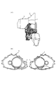
図3は変速機ユニットのハウジング構成を表す概念図である。
図3(イ)に示すように、このような変速機構及びモータ等を収装した変速機ハウジングは、CVT13を収装した第3ハウジング49と、CVT13とAモータ15とを収装した第2ハウジング41と、Aモータと電磁クラッチ11を収装した第1ハウジング42とに軸方向に分割した構成となっている。
【0028】
第2ハウジング41はCVT13等が組み込まれる変速機室43とAモータ15が組み込まれるモータ室44とに第2隔壁45と第4隔壁71を介して仕切られている。また、従動軸23の支持部を介してCVT13の駆動プーリ14と従動プーリ18が収装されている部分を第1ウエット室とし、アイドラ軸27やディファレンシャル31が収装されている部分を第2ウエット室として構成している。また、図4の第2ハウジング41の正面図に示すように、この第4隔壁71にはパーキングギヤを操作するためのマニュアルシャフト支持部62bが設けられ、これにより構造の簡素化、及びケース内のレイアウト自由度の向上を図っている。
【0029】
また、第3隔壁70及び第4隔壁71はAモータ15への3相電流供給用のハーネス部66を画成することで、3相電流供給用のハーネスをモータ室44を通して配線することができるよう構成されている。
【0030】
第1ハウジング42は前記第2ハウジング41が結合する一方の端面に第2ドライ室の一部を設けるように第1隔壁46が形成されるとともに、従動軸23,アイドラ軸27及びディファレンシャル31が構成される第2ウエット室とモータ室44を画成する第3隔壁70が形成され、各ハウジング41,42を結合したときに前記各隔壁45,46,70,71間に前記モータ室44を画成すると共に、第1ハウジング42の他方の端面を図示しないエンジン2に結合したときに第1隔壁46とエンジン2との間にクラッチ室47を画成するように構成されている。
【0031】
次に、各ハウジング41,42を結合する際のシールフランジ面について説明する。図3(ロ)に示すように、第2ハウジング41のモータ室44と従動軸23が収装される従動軸収装部63との間には、肉厚部73が形成され、その端面は一部がシールフランジ面を形成している。
また、第1ハウジング42及び第2ハウジング41の外周部端面には、シールフランジ面が形成されると共に、第3隔壁及び第4隔壁の端面にもそれぞれシールフランジ面が形成され、これらのシールフランジ面は同一平面上に形成されている。
【0032】
このように、第1及び第2ハウジング41,42のシールフランジ面を同一平面上に構成することにより、確実にシールされたモータ室44を形成することができる。また、シールフランジ面が同一面内に形成されているため、製造上の公差管理を容易に行うことが可能となり、精度の高いシールフランジ面を形成することができる。また、モータ室44を第1ハウジング42と第2ハウジング41の両方から構成しているため、モータ室44の容積を十分に確保することができる。
【0033】
図4は第2ハウジング41の正面図(第一ハウジングとの合わせ面)を示す。第2ハウジング41には、モータ収装部61とパーキングサポート収装部62aとマニュアルシャフト支持部62bと従動軸収装部63とアイドラ軸収装部64とディファレンシャル収装部65が設けられている。また、図中ハッチング領域がシールフランジ面であり、ドライ室及びウエット室の画成は、このハッチング領域のシールフランジ面によって行われる。
【0034】
この第2ハウジング41を鋳造する際、湯口が肉厚部73に設けられている。ここで、第2ハウジング41のモータ収装部外周には、Aモータ15のステータ17を冷却するためのウォータジャケット48が設けられ、また、従動軸収装部63には、耐摩耗性スリーブ80が鋳込まれている。
【0035】
このように、湯口付近に鋳込む耐摩耗性スリーブ80を備え、かつ、ウォータジャケットを備えた第2ハウジング41を鋳造する場合、ウォータジャケット成形用の砂中子を有するため、ロープレッシャダイカスト工法がとられる。この工法は、湯口から高温のアルミが流れ込み、かつ、低圧で成形するため、高温に溶けたアルミを型中に保持する時間が長い。よって、湯口付近にある耐摩耗性スリーブ80の厚みを厚く設定し、鋳込み時の内径を小径化することで熱容量を高め、溶損不良と密着不良を最適化し、溶損率の低減を図っている。
【0036】
このように、第2ハウジングのAモータ15と従動軸23の間である肉厚部73を肉厚に形成したことで、入力軸12及び従動軸23に大きなトルクや荷重がかかったとしても、入力軸12と従動軸23の軸穴位置度を精度良く保つことができる。
【0037】
以上説明したように、本実施の形態におけるハイブリッド車両の変速機ユニットにおいては、電磁クラッチ11とAモータ15とCVT13が入力軸12上に直列に配置されるとともに、従動軸23が少なくともAモータ15と重なるように並列に配置されている。この変速機ユニット1のユニットハウジングが、第1ハウジング42と第2ハウジング41と第3ハウジング49から構成され、第1ハウジング42に電磁クラッチ11を収装するクラッチ室47とAモータ15を収装するモータ室44を画成する第1隔壁46と、クラッチ室47及びモータ室44と従動軸23を収装する第2ウエット室を画成する第3隔壁70が備えられている。そして、第2ハウジング41にモータ室44と第1ウエット室を軸方向に画成する第2隔壁45と、モータ室44と第1ウエット室を径方向に画成する第4隔壁71が備えられている。そして、第1ハウジング42のハウジング外周の端面、及び第3隔壁70の端面に形成された第1シールフランジ面が同一平面上に、かつ、前記モータの外周を取り囲むように連続して形成されると共に、第2ハウジング41のハウジング外周の端面、及び第4隔壁71の端面に形成された第2シールフランジ面が同一平面上に、かつ、前記モータの外周を取り囲むように連続して形成され、第1ハウジング42と第2ハウジング41が第1及び第2シールフランジ面により接合されている。
【0038】
すなわち、ハイブリッド車両の変速機ユニットでは、電磁クラッチ室及びモータ室はドライ室として構成しなければならない。ここで、モータ室44を第1ハウジング42と第2ハウジング41から構成することで、Aモータ15の組み付け性の向上を図りつつ、モータ室44を広く確保することができる。
また、同一面内に油室であるウエット室が構成されているため、モータ室44とウエット室を確実にシールする必要があるが、モータ室44を第1及び第2シールフランジ面により接合することで、確実にシールされたドライ室を形成することができる。
また、シールフランジ面が同一面内に形成されているため、製造上の公差管理を容易に行うことが可能となり、精度の高いシールフランジ面を形成することができる。
【0039】
また、第4隔壁71であって、Aモータ15と従動軸23の間が肉厚に形成されている。
よって、入力軸12及び従動軸23に大きなトルクや荷重がかかったとしても、入力軸12と従動軸23軸穴位置度を精度良く保つことができる。
【図面の簡単な説明】
【図1】実施の形態におけるハイブリッド車両の主要ユニットの構成を示す図である。
【図2】実施の形態におけるベルト式無段変速機(CVT)を備えたハイブリッド車両の変速機ユニットの断面図である。
【図3】実施の形態におけるユニットハウジングの概念図である。
【図4】実施の形態における第2ハウジングの正面図である。
【図5】従来技術を表す図である。
【符号の説明】
1 変速機ユニット
2 エンジン
3 Bモータ
5 バッテリ
6 パワーステアリング
7 ハイブリッド制御ユニット
7a バッテリ制御ユニット
7b モータ制御ユニット
7c エンジン制御ユニット
7e CVT制御ユニット
7d クラッチ制御ユニット
8 チェーン
9 Cモータ
10 エンジン出力軸
11a スリップリング
11 電磁クラッチ
12 入力軸
14 駆動プーリ
15 Aモータ
16 ロータ
17 ステータ
18 従動プーリ
19 ベルト
20 固定円錐板
21 駆動プーリシリンダ室
22 可動円錐板
23 従動軸
24 固定円錐板
25 可動円錐板
26 駆動ギア
27 アイドラ軸
28 アイドラギア
29 ピニオン
30 ファイナルギア
31 ディファレンシャル
32 従動プーリシリンダ室
41 第2ハウジング
42 第1ハウジング
43 変速機室
44 モータ室
45 第2隔壁
46 第1隔壁
47 クラッチ室
48 冷却水ジャケット
61 モータ収装部
62a パーキングサポート収装部
62b マニュアルシャフト支持部
63 従動軸収装部
64 アイドラ軸収装部
65 ディファレンシャル収装部
66 ハーネス部
70 第3隔壁
71 第4隔壁
73 肉厚部
80 耐摩耗性スリーブ
a ケース
b ケース
c 合わせ面[0001]
BACKGROUND OF THE INVENTION
The present invention includes a hybrid vehicle that has an engine and a motor that also serves as a generator, and that transmits driving torque to one or both of the engine and the motor by transmitting these output torques to the transmission. The present invention relates to a transmission unit to be mounted on
[0002]
[Prior art]
Conventionally, in a housing structure of a transmission unit, for example the technique described in the real Hei 2-62157 JP are known. As shown in FIG. 5 (a), it is composed of a case a and a case b, and the flange structure of the mating surface c of the case a and the case b is only at the outer periphery of the case as shown in FIG. It is what is joined.
[0003]
[Problems to be solved by the invention]
However, the above-described prior art has the following problems. That is, when configuring a transmission unit of a hybrid vehicle incorporating a motor, a motor chamber must be configured in the case. However, it is necessary to keep the motor chamber dry (in a state where oil or the like is not lubricated), and it is difficult to maintain the sealing performance with the wet chamber in which the transmission or the like is accommodated.
In addition, it is conceivable that a motor housing is separately provided in the transmission unit housing to define the motor chamber as a dry chamber, but there is a problem in that the number of parts is increased.
[0004]
The present invention has been made paying attention to the above-described problems, and in the transmission unit of a hybrid vehicle, the dry chamber in which the motor is accommodated is surely sealed, and the number of parts is increased. It is an object of the present invention to provide a transmission unit housing without a gap.
[0005]
[Means for Solving the Problems]
In the first aspect of the present invention, a motor and a transmission, which are composed of an electromagnetic clutch, a stator, and a rotor that connect and disconnect the engine and the transmission input shaft, and that serve as a drive source together with the engine are arranged in series on the transmission input shaft. In addition, in a transmission unit of a hybrid vehicle that is arranged in parallel so that a transmission output shaft overlaps at least the motor, a unit housing of the transmission unit is provided with a first housing and a second housing in an axial direction from the engine side. A wet chamber configured with a third housing and allowing oil for controlling and lubricating the transmission in the first, second, and third housings, and not permitting oil for controlling and lubricating the transmission A first dry chamber that includes a dry chamber and accommodates an electromagnetic clutch in the first housing and a second dry chamber that accommodates the motor are arranged in an axial direction. A first partition that defines the first partition, a third partition that radially defines a first wet chamber that houses the first and second dry chambers, the transmission output shaft, the idler shaft, and the differential; A second partition that axially defines a first wet chamber for housing the second dry chamber and a transmission in a housing; and a second partition that radially defines the second dry chamber and the second wet chamber. Four partition walls are provided, and the end surface of the outer periphery of the first housing and the first seal flange surface formed on the end surface of the third partition wall are formed on the same plane continuously so as to surround the outer periphery of the motor. And forming a second seal flange surface formed on an end surface of the outer periphery of the second housing and an end surface of the fourth partition wall on the same plane and continuously surrounding the outer periphery of the motor , 1st housing Characterized in that said second housing is joined by the first and second sealing flange surface.
[0006]
In the invention according to
A pouring gate for casting the second housing is provided between the motor and the transmission output shaft in the vicinity of the second seal flange surface of the fourth partition wall, so that the meat continuous with the fourth partition wall is provided. A rigid support portion is formed by forming a thick portion.
[0007]
[Action and effect of the invention]
In the transmission unit of the hybrid vehicle according to claim 1, a motor and a transmission which are composed of an electromagnetic clutch, a stator and a rotor which connect and disconnect the engine and the transmission input shaft, and which serve as a drive source together with the engine are disposed on the transmission input shaft. They are arranged in series and arranged in parallel so that the transmission output shaft overlaps at least the motor. At this time, the unit housing of the transmission unit is constituted by the first housing, the second housing, and the third housing in the axial direction from the engine side, and the transmission control and the first housing are provided in the first, second, and third housings. A wet chamber that allows lubricating oil and a dry chamber that does not allow oil for controlling the transmission and lubricating are provided. And a first partition that axially defines a first dry chamber for housing the electromagnetic clutch in the first housing and a second dry chamber for housing the motor, the first and second dry chambers, and a transmission output shaft. , A third partition that radially defines a second wet chamber that houses the idler shaft and the differential. In addition, the second dry chamber and the first wet chamber for housing the transmission in the second housing are defined in the axial direction, the second partition wall, and the second dry chamber and the second wet chamber are defined in the radial direction. A fourth partition wall is provided. And the end face of the housing outer periphery of the first housing and the first seal flange surface formed on the end face of the third partition wall are continuously formed on the same plane so as to surround the outer periphery of the motor, The end face of the housing outer periphery of the housing and the second seal flange face formed on the end face of the fourth partition wall are formed continuously on the same plane so as to surround the outer periphery of the motor . The first housing and the second housing are joined by the first and second seal flange surfaces.
[0008]
That is, in the transmission unit of the hybrid vehicle, the electromagnetic clutch chamber and the motor chamber must be configured as a dry chamber. Here, by configuring the second dry chamber, which is a motor chamber, from the first housing and the second housing, a wide motor chamber can be secured while improving the assembling property of the motor. In addition, since the wet chamber that is the oil chamber is configured in the same plane, it is necessary to securely seal the second dry chamber and the second wet chamber. By joining by the 2nd seal flange surface, the dry chamber sealed reliably can be formed. In addition, since the seal flange surface is continuously formed in the same plane and surrounding the outer periphery of the motor , manufacturing tolerance management can be easily performed, and a highly accurate seal flange surface Can be formed.
[0009]
In the transmission unit of the hybrid vehicle according to
Therefore, even if a large torque or load is applied to the transmission input shaft and the output shaft, the shaft hole position degree of the transmission input shaft and the output shaft can be accurately maintained.
[0010]
DETAILED DESCRIPTION OF THE INVENTION
Hereinafter, embodiments of the present invention will be described with reference to the drawings.
FIG. 1 is a diagram showing a configuration of main units of a hybrid vehicle in the embodiment.
1 is a transmission unit, 2 is an engine, 3 is a B motor for power generation / starting, 4 is an inverter, 5 is a battery, 6 is an electric power steering, 7 is a hybrid control unit, and 8 is a chain.
[0011]
In the transmission unit 1, an
[0012]
The B motor 3 which is a power generation / starting motor is mounted on the engine block and is connected to the
The
[0013]
Next, the operation of the drive system will be described.
The hybrid vehicle of the present embodiment is a parallel system, and the
The clutch 11 is an electromagnetic clutch. When the clutch 11 is turned off, only the
[0014]
(At system startup)
At the time of starting, the B motor 3 functions as a starter and starts the
[0015]
(When starting and running at low speed)
When the
[0016]
(During normal driving)
It is mainly driven by the
[0017]
(High load)
When the
[0018]
(During deceleration)
During deceleration, the
[0019]
(When retreating)
The reverse gear is not set in CVT13. Accordingly, when reversing, the clutch 11 is released, the
[0020]
(When stopped)
When the vehicle stops, the
[0021]
FIG. 2 is a sectional view of a transmission unit of a hybrid vehicle provided with a belt type continuously variable transmission (CVT) according to the present invention.
In FIG. 2, the
[0022]
The
[0023]
The
[0024]
A
[0025]
The rotational force input from the
[0026]
When the power is transmitted as described above, the movable
[0027]
FIG. 3 is a conceptual diagram showing the housing configuration of the transmission unit.
As shown in FIG. 3A, the transmission housing in which such a speed change mechanism and a motor are accommodated is the
[0028]
The
[0029]
Further, the
[0030]
The
[0031]
Next, the seal flange surface when connecting the
In addition, seal flange surfaces are formed on the outer peripheral end surfaces of the
[0032]
Thus, the
[0033]
FIG. 4 is a front view of the second housing 41 (a mating surface with the first housing). The
[0034]
When casting the
[0035]
In this way, when the
[0036]
Thus, even if a large torque or load is applied to the
[0037]
As described above, in the transmission unit of the hybrid vehicle in the present embodiment, electromagnetic clutch 11, A
[0038]
That is, in the transmission unit of the hybrid vehicle, the electromagnetic clutch chamber and the motor chamber must be configured as a dry chamber. Here, by configuring the
In addition, since the wet chamber which is an oil chamber is formed in the same plane, it is necessary to securely seal the
In addition, since the seal flange surface is formed in the same plane, manufacturing tolerance management can be easily performed, and a highly accurate seal flange surface can be formed.
[0039]
Moreover, it is the
Therefore, even if a large torque or load is applied to the
[Brief description of the drawings]
FIG. 1 is a diagram showing a configuration of main units of a hybrid vehicle in an embodiment.
FIG. 2 is a cross-sectional view of a transmission unit of a hybrid vehicle including a belt type continuously variable transmission (CVT) according to an embodiment.
FIG. 3 is a conceptual diagram of a unit housing in the embodiment.
FIG. 4 is a front view of a second housing in the embodiment.
FIG. 5 is a diagram showing a conventional technique.
[Explanation of symbols]
DESCRIPTION OF SYMBOLS 1
Claims (2)
前記変速機ユニットのユニットハウジングを、エンジン側から軸方向に第1ハウジングと第2ハウジングと第3ハウジングから構成し、
前記第1、第2、及び第3ハウジング内に前記変速機の制御及び潤滑用の油を許容するウエット室と、前記変速機の制御及び潤滑用の油を許容しないドライ室を備え、
前記第1ハウジングに電磁クラッチを収装する第1ドライ室と前記モータを収装する第2ドライ室を軸方向に画成する第1隔壁と、
前記第1及び第2ドライ室と前記変速機出力軸,アイドラ軸及びディファレンシャルを収装する第2ウエット室を径方向に画成する第3隔壁を備え、
前記第2ハウジングに前記第2ドライ室と変速機を収装する第1ウエット室を軸方向に画成する第2隔壁と、
前記第2ドライ室と前記第2ウエット室を径方向に画成する第4隔壁を備え、前記第1ハウジングのハウジング外周の端面、及び第3隔壁の端面に形成された第1シールフランジ面を同一平面上に、かつ、前記モータの外周を取り囲むように連続して形成し、
前記第2ハウジングのハウジング外周の端面、及び第4隔壁の端面に形成された第2シールフランジ面を同一平面上に、かつ、前記モータの外周を取り囲むように連続して形成し、
前記第1ハウジングと前記第2ハウジングを前記第1及び第2シールフランジ面により接合したことを特徴とするハイブリッド車両の変速機ユニット。A motor and a transmission that are composed of an electromagnetic clutch, a stator, and a rotor that connect and disconnect the engine and the transmission input shaft and that are a drive source together with the engine are arranged in series on the transmission input shaft, and at least the transmission output shaft is the motor In a transmission unit of a hybrid vehicle arranged in parallel so as to overlap with
A unit housing of the transmission unit is configured by a first housing, a second housing, and a third housing in an axial direction from the engine side;
A wet chamber allowing oil for controlling and lubricating the transmission and a dry chamber not allowing oil for controlling and lubricating the transmission in the first, second and third housings;
A first partition that axially defines a first dry chamber that houses an electromagnetic clutch in the first housing and a second dry chamber that houses the motor;
A third partition that radially defines the first and second dry chambers, the transmission output shaft, the idler shaft, and a second wet chamber that houses the differential;
A second partition that defines, in the axial direction, a first wet chamber for housing the second dry chamber and the transmission in the second housing;
A fourth partition that radially defines the second dry chamber and the second wet chamber; and a first seal flange surface formed on an end surface of the outer periphery of the housing of the first housing and an end surface of the third partition. On the same plane and continuously so as to surround the outer periphery of the motor ,
Forming a second seal flange surface formed on an end surface of the outer periphery of the second housing and an end surface of the fourth partition wall on the same plane and continuously surrounding the outer periphery of the motor ;
A transmission unit for a hybrid vehicle, wherein the first housing and the second housing are joined by the first and second seal flange surfaces.
前記第4隔壁の前記第2シールフランジ面近傍であって、前記モータと前記変速機出力軸の間に前記第2ハウジングを鋳込む際の湯口を設け、これにより前記第4隔壁と連続した肉厚部を形成することで剛性支持部としたことを特徴とするハイブリッド車両の変速機ユニット。In the transmission unit of the hybrid vehicle according to claim 1,
A pouring gate for casting the second housing is provided between the motor and the transmission output shaft in the vicinity of the second seal flange surface of the fourth partition wall, and thereby, the meat continuous with the fourth partition wall is provided. A transmission unit for a hybrid vehicle, characterized in that a rigid support portion is formed by forming a thick portion.
Priority Applications (2)
| Application Number | Priority Date | Filing Date | Title |
|---|---|---|---|
| JP2000079548A JP3708784B2 (en) | 2000-03-22 | 2000-03-22 | Hybrid vehicle transmission unit |
| US09/785,455 US6513609B2 (en) | 2000-03-22 | 2001-02-20 | Transmission unit for hybrid vehicle |
Applications Claiming Priority (1)
| Application Number | Priority Date | Filing Date | Title |
|---|---|---|---|
| JP2000079548A JP3708784B2 (en) | 2000-03-22 | 2000-03-22 | Hybrid vehicle transmission unit |
Publications (3)
| Publication Number | Publication Date |
|---|---|
| JP2001260673A JP2001260673A (en) | 2001-09-26 |
| JP2001260673A5 JP2001260673A5 (en) | 2004-07-08 |
| JP3708784B2 true JP3708784B2 (en) | 2005-10-19 |
Family
ID=18596783
Family Applications (1)
| Application Number | Title | Priority Date | Filing Date |
|---|---|---|---|
| JP2000079548A Expired - Fee Related JP3708784B2 (en) | 2000-03-22 | 2000-03-22 | Hybrid vehicle transmission unit |
Country Status (2)
| Country | Link |
|---|---|
| US (1) | US6513609B2 (en) |
| JP (1) | JP3708784B2 (en) |
Families Citing this family (15)
| Publication number | Priority date | Publication date | Assignee | Title |
|---|---|---|---|---|
| JP2001099039A (en) * | 1999-09-30 | 2001-04-10 | Suzuki Motor Corp | Control device of engine-connected type motor |
| JP3820842B2 (en) | 2000-04-05 | 2006-09-13 | スズキ株式会社 | Control device for hybrid vehicle |
| US6837323B2 (en) | 2001-06-18 | 2005-01-04 | Visteon Global Technologies Inc. | Variable shift schedule control |
| US6781252B2 (en) * | 2002-03-14 | 2004-08-24 | Ford Global Technologies, Llc | Method and apparatus for starting an engine using a starter/alternator and an accessory drive |
| JP2004180477A (en) * | 2002-11-29 | 2004-06-24 | Honda Motor Co Ltd | Cooling structure of motor in front and rear wheel drive vehicle |
| WO2006038224A2 (en) | 2004-10-08 | 2006-04-13 | Indian Institute Of Technology Bombay | A hybrid transmission system |
| FR2882699B1 (en) * | 2005-03-01 | 2008-10-31 | Peugeot Citroen Automobiles Sa | METHOD OF TAKING A VEHICLE UP AND DOWN AND LOADING |
| JP4539531B2 (en) * | 2005-10-26 | 2010-09-08 | トヨタ自動車株式会社 | Vehicle drive device |
| US7605493B1 (en) | 2005-11-09 | 2009-10-20 | Joseph P. Boudreaux | Electrically powered vehicle engine |
| US20080099258A1 (en) * | 2006-10-26 | 2008-05-01 | Berhan Michael T | Vented sealed housing assembly for vehicle powertrain |
| JP4397927B2 (en) * | 2006-12-28 | 2010-01-13 | 本田技研工業株式会社 | Motorcycle engine |
| US8649925B2 (en) * | 2010-08-30 | 2014-02-11 | Ford Global Technologies, Llc | Method and system for controlling operation of an electric oil pump in a hybrid electric vehicle (HEV) |
| JP6639328B2 (en) * | 2016-05-25 | 2020-02-05 | トヨタ自動車株式会社 | Power transmission device lubrication structure |
| US10808830B2 (en) * | 2018-11-30 | 2020-10-20 | Arvinmeritor Technology, Llc | Axle assembly with multiple lubricant chambers |
| DE102021101049A1 (en) * | 2021-01-19 | 2022-07-21 | Audi Aktiengesellschaft | Electrical machine comprising a cooling and/or lubricating system with a wet area, motor vehicle with an electrical machine |
Family Cites Families (17)
| Publication number | Priority date | Publication date | Assignee | Title |
|---|---|---|---|---|
| JPS6131576Y2 (en) * | 1980-07-25 | 1986-09-13 | ||
| JPH0633810B2 (en) * | 1984-02-01 | 1994-05-02 | 富士重工業株式会社 | Lubrication device for continuously variable transmission |
| JPH02107859A (en) * | 1988-07-07 | 1990-04-19 | Toyota Motor Corp | Planetary gear device |
| JPH0262157A (en) | 1988-08-29 | 1990-03-02 | Oki Electric Ind Co Ltd | Led array control circuit |
| US5440951A (en) * | 1993-07-30 | 1995-08-15 | Kanzaki Kokyukoki Mfg. Co., Ltd. | Axle driving system |
| JP3075153B2 (en) * | 1995-09-11 | 2000-08-07 | トヨタ自動車株式会社 | Power transmission mechanism of internal combustion engine |
| US5913950A (en) * | 1996-01-08 | 1999-06-22 | Kanzaki Kokyukoki Mfg. Co., Ltd. | Transmission for a working vehicle |
| JP3045063B2 (en) * | 1996-02-21 | 2000-05-22 | トヨタ自動車株式会社 | Hybrid drive |
| US5901606A (en) * | 1996-06-18 | 1999-05-11 | Kubota Corporation | Transmission for a tractor |
| JPH10103429A (en) * | 1996-09-30 | 1998-04-21 | Mazda Motor Corp | Gear type transmission structure |
| JPH11189073A (en) * | 1997-12-25 | 1999-07-13 | Nissan Motor Co Ltd | Fluid pressure control device for hybrid vehicle |
| JP3853963B2 (en) * | 1998-03-20 | 2006-12-06 | 本田技研工業株式会社 | Power unit |
| JP3653991B2 (en) * | 1998-06-22 | 2005-06-02 | 日産自動車株式会社 | Hybrid drive device |
| JP3572947B2 (en) * | 1998-06-22 | 2004-10-06 | 日産自動車株式会社 | Transmission structure |
| JP3005528B1 (en) * | 1998-07-24 | 2000-01-31 | 本田技研工業株式会社 | Transmission for vehicles |
| JP3491815B2 (en) * | 1998-11-13 | 2004-01-26 | 日産自動車株式会社 | Drive unit for hybrid vehicle |
| JP3691718B2 (en) * | 2000-03-22 | 2005-09-07 | ジヤトコ株式会社 | Hybrid vehicle transmission unit |
-
2000
- 2000-03-22 JP JP2000079548A patent/JP3708784B2/en not_active Expired - Fee Related
-
2001
- 2001-02-20 US US09/785,455 patent/US6513609B2/en not_active Expired - Lifetime
Also Published As
| Publication number | Publication date |
|---|---|
| JP2001260673A (en) | 2001-09-26 |
| US20010023790A1 (en) | 2001-09-27 |
| US6513609B2 (en) | 2003-02-04 |
Similar Documents
| Publication | Publication Date | Title |
|---|---|---|
| JP3708784B2 (en) | Hybrid vehicle transmission unit | |
| JP3691718B2 (en) | Hybrid vehicle transmission unit | |
| US6114784A (en) | Motor with cooling structure | |
| JP3625170B2 (en) | Hybrid vehicle transmission unit | |
| JP4876568B2 (en) | Cooling structure of motor generator for hybrid vehicles | |
| JP3714845B2 (en) | Transmission unit | |
| JP2006123896A (en) | Axle assembly for motor vehicle, and car propulsion method | |
| US8505659B2 (en) | Road vehicle with hybrid propulsion | |
| JP5644999B2 (en) | Clutch and motor housing structure of hybrid electric vehicle | |
| JP3691717B2 (en) | Hybrid vehicle transmission unit | |
| EP2937238B1 (en) | Hybrid vehicle drive device | |
| JP4900683B2 (en) | Hydraulic supply device | |
| JP2006504572A (en) | Automotive drive unit | |
| JP3578151B2 (en) | Hydraulic supply device for hybrid vehicle | |
| JP2005282643A (en) | Electric assist oil pump unit for transmission | |
| JP3558277B2 (en) | Transmission unit for hybrid vehicle | |
| JP5347523B2 (en) | Motor with built-in housing | |
| JP5429252B2 (en) | Vehicle drive device | |
| JP3571991B2 (en) | Transmission unit | |
| JP3643751B2 (en) | Hybrid vehicle transmission unit | |
| JP5326657B2 (en) | Assembling method of motor unit with built-in housing and motor unit with built-in housing | |
| JP3691720B2 (en) | Transmission unit | |
| JP3691719B2 (en) | Breather pipe installation method | |
| JP3571990B2 (en) | Transmission unit for hybrid vehicle | |
| JPH11190417A (en) | Lubricating mechanism of electric vehicle |
Legal Events
| Date | Code | Title | Description |
|---|---|---|---|
| RD04 | Notification of resignation of power of attorney |
Free format text: JAPANESE INTERMEDIATE CODE: A7424 Effective date: 20041111 |
|
| RD02 | Notification of acceptance of power of attorney |
Free format text: JAPANESE INTERMEDIATE CODE: A7422 Effective date: 20050304 |
|
| A131 | Notification of reasons for refusal |
Free format text: JAPANESE INTERMEDIATE CODE: A131 Effective date: 20050510 |
|
| A521 | Written amendment |
Free format text: JAPANESE INTERMEDIATE CODE: A523 Effective date: 20050707 |
|
| TRDD | Decision of grant or rejection written | ||
| A01 | Written decision to grant a patent or to grant a registration (utility model) |
Free format text: JAPANESE INTERMEDIATE CODE: A01 Effective date: 20050802 |
|
| A61 | First payment of annual fees (during grant procedure) |
Free format text: JAPANESE INTERMEDIATE CODE: A61 Effective date: 20050804 |
|
| R150 | Certificate of patent or registration of utility model |
Free format text: JAPANESE INTERMEDIATE CODE: R150 |
|
| FPAY | Renewal fee payment (event date is renewal date of database) |
Free format text: PAYMENT UNTIL: 20080812 Year of fee payment: 3 |
|
| FPAY | Renewal fee payment (event date is renewal date of database) |
Free format text: PAYMENT UNTIL: 20090812 Year of fee payment: 4 |
|
| FPAY | Renewal fee payment (event date is renewal date of database) |
Free format text: PAYMENT UNTIL: 20090812 Year of fee payment: 4 |
|
| FPAY | Renewal fee payment (event date is renewal date of database) |
Free format text: PAYMENT UNTIL: 20100812 Year of fee payment: 5 |
|
| FPAY | Renewal fee payment (event date is renewal date of database) |
Free format text: PAYMENT UNTIL: 20100812 Year of fee payment: 5 |
|
| FPAY | Renewal fee payment (event date is renewal date of database) |
Free format text: PAYMENT UNTIL: 20110812 Year of fee payment: 6 |
|
| FPAY | Renewal fee payment (event date is renewal date of database) |
Free format text: PAYMENT UNTIL: 20110812 Year of fee payment: 6 |
|
| FPAY | Renewal fee payment (event date is renewal date of database) |
Free format text: PAYMENT UNTIL: 20120812 Year of fee payment: 7 |
|
| FPAY | Renewal fee payment (event date is renewal date of database) |
Free format text: PAYMENT UNTIL: 20120812 Year of fee payment: 7 |
|
| FPAY | Renewal fee payment (event date is renewal date of database) |
Free format text: PAYMENT UNTIL: 20130812 Year of fee payment: 8 |
|
| FPAY | Renewal fee payment (event date is renewal date of database) |
Free format text: PAYMENT UNTIL: 20130812 Year of fee payment: 8 |
|
| FPAY | Renewal fee payment (event date is renewal date of database) |
Free format text: PAYMENT UNTIL: 20140812 Year of fee payment: 9 |
|
| LAPS | Cancellation because of no payment of annual fees |