EP2937238B1 - Hybrid vehicle drive device - Google Patents
Hybrid vehicle drive device Download PDFInfo
- Publication number
- EP2937238B1 EP2937238B1 EP13865470.2A EP13865470A EP2937238B1 EP 2937238 B1 EP2937238 B1 EP 2937238B1 EP 13865470 A EP13865470 A EP 13865470A EP 2937238 B1 EP2937238 B1 EP 2937238B1
- Authority
- EP
- European Patent Office
- Prior art keywords
- electric motor
- engine
- transmission
- transmission mechanism
- power transmission
- Prior art date
- Legal status (The legal status is an assumption and is not a legal conclusion. Google has not performed a legal analysis and makes no representation as to the accuracy of the status listed.)
- Not-in-force
Links
- 230000005540 biological transmission Effects 0.000 claims description 98
- 239000007858 starting material Substances 0.000 description 4
- 230000006866 deterioration Effects 0.000 description 3
- 230000001172 regenerating effect Effects 0.000 description 3
- 230000000694 effects Effects 0.000 description 2
- 238000005516 engineering process Methods 0.000 description 2
- 239000012530 fluid Substances 0.000 description 2
- 230000001133 acceleration Effects 0.000 description 1
- 238000007599 discharging Methods 0.000 description 1
Images


Classifications
-
- B—PERFORMING OPERATIONS; TRANSPORTING
- B60—VEHICLES IN GENERAL
- B60K—ARRANGEMENT OR MOUNTING OF PROPULSION UNITS OR OF TRANSMISSIONS IN VEHICLES; ARRANGEMENT OR MOUNTING OF PLURAL DIVERSE PRIME-MOVERS IN VEHICLES; AUXILIARY DRIVES FOR VEHICLES; INSTRUMENTATION OR DASHBOARDS FOR VEHICLES; ARRANGEMENTS IN CONNECTION WITH COOLING, AIR INTAKE, GAS EXHAUST OR FUEL SUPPLY OF PROPULSION UNITS IN VEHICLES
- B60K6/00—Arrangement or mounting of plural diverse prime-movers for mutual or common propulsion, e.g. hybrid propulsion systems comprising electric motors and internal combustion engines ; Control systems therefor, i.e. systems controlling two or more prime movers, or controlling one of these prime movers and any of the transmission, drive or drive units Informative references: mechanical gearings with secondary electric drive F16H3/72; arrangements for handling mechanical energy structurally associated with the dynamo-electric machine H02K7/00; machines comprising structurally interrelated motor and generator parts H02K51/00; dynamo-electric machines not otherwise provided for in H02K see H02K99/00
- B60K6/20—Arrangement or mounting of plural diverse prime-movers for mutual or common propulsion, e.g. hybrid propulsion systems comprising electric motors and internal combustion engines ; Control systems therefor, i.e. systems controlling two or more prime movers, or controlling one of these prime movers and any of the transmission, drive or drive units Informative references: mechanical gearings with secondary electric drive F16H3/72; arrangements for handling mechanical energy structurally associated with the dynamo-electric machine H02K7/00; machines comprising structurally interrelated motor and generator parts H02K51/00; dynamo-electric machines not otherwise provided for in H02K see H02K99/00 the prime-movers consisting of electric motors and internal combustion engines, e.g. HEVs
- B60K6/22—Arrangement or mounting of plural diverse prime-movers for mutual or common propulsion, e.g. hybrid propulsion systems comprising electric motors and internal combustion engines ; Control systems therefor, i.e. systems controlling two or more prime movers, or controlling one of these prime movers and any of the transmission, drive or drive units Informative references: mechanical gearings with secondary electric drive F16H3/72; arrangements for handling mechanical energy structurally associated with the dynamo-electric machine H02K7/00; machines comprising structurally interrelated motor and generator parts H02K51/00; dynamo-electric machines not otherwise provided for in H02K see H02K99/00 the prime-movers consisting of electric motors and internal combustion engines, e.g. HEVs characterised by apparatus, components or means specially adapted for HEVs
- B60K6/40—Arrangement or mounting of plural diverse prime-movers for mutual or common propulsion, e.g. hybrid propulsion systems comprising electric motors and internal combustion engines ; Control systems therefor, i.e. systems controlling two or more prime movers, or controlling one of these prime movers and any of the transmission, drive or drive units Informative references: mechanical gearings with secondary electric drive F16H3/72; arrangements for handling mechanical energy structurally associated with the dynamo-electric machine H02K7/00; machines comprising structurally interrelated motor and generator parts H02K51/00; dynamo-electric machines not otherwise provided for in H02K see H02K99/00 the prime-movers consisting of electric motors and internal combustion engines, e.g. HEVs characterised by apparatus, components or means specially adapted for HEVs characterised by the assembly or relative disposition of components
- B60K6/405—Housings
-
- B—PERFORMING OPERATIONS; TRANSPORTING
- B60—VEHICLES IN GENERAL
- B60K—ARRANGEMENT OR MOUNTING OF PROPULSION UNITS OR OF TRANSMISSIONS IN VEHICLES; ARRANGEMENT OR MOUNTING OF PLURAL DIVERSE PRIME-MOVERS IN VEHICLES; AUXILIARY DRIVES FOR VEHICLES; INSTRUMENTATION OR DASHBOARDS FOR VEHICLES; ARRANGEMENTS IN CONNECTION WITH COOLING, AIR INTAKE, GAS EXHAUST OR FUEL SUPPLY OF PROPULSION UNITS IN VEHICLES
- B60K5/00—Arrangement or mounting of internal-combustion or jet-propulsion units
- B60K5/04—Arrangement or mounting of internal-combustion or jet-propulsion units with the engine main axis, e.g. crankshaft axis, transversely to the longitudinal centre line of the vehicle
-
- B—PERFORMING OPERATIONS; TRANSPORTING
- B60—VEHICLES IN GENERAL
- B60K—ARRANGEMENT OR MOUNTING OF PROPULSION UNITS OR OF TRANSMISSIONS IN VEHICLES; ARRANGEMENT OR MOUNTING OF PLURAL DIVERSE PRIME-MOVERS IN VEHICLES; AUXILIARY DRIVES FOR VEHICLES; INSTRUMENTATION OR DASHBOARDS FOR VEHICLES; ARRANGEMENTS IN CONNECTION WITH COOLING, AIR INTAKE, GAS EXHAUST OR FUEL SUPPLY OF PROPULSION UNITS IN VEHICLES
- B60K6/00—Arrangement or mounting of plural diverse prime-movers for mutual or common propulsion, e.g. hybrid propulsion systems comprising electric motors and internal combustion engines ; Control systems therefor, i.e. systems controlling two or more prime movers, or controlling one of these prime movers and any of the transmission, drive or drive units Informative references: mechanical gearings with secondary electric drive F16H3/72; arrangements for handling mechanical energy structurally associated with the dynamo-electric machine H02K7/00; machines comprising structurally interrelated motor and generator parts H02K51/00; dynamo-electric machines not otherwise provided for in H02K see H02K99/00
- B60K6/20—Arrangement or mounting of plural diverse prime-movers for mutual or common propulsion, e.g. hybrid propulsion systems comprising electric motors and internal combustion engines ; Control systems therefor, i.e. systems controlling two or more prime movers, or controlling one of these prime movers and any of the transmission, drive or drive units Informative references: mechanical gearings with secondary electric drive F16H3/72; arrangements for handling mechanical energy structurally associated with the dynamo-electric machine H02K7/00; machines comprising structurally interrelated motor and generator parts H02K51/00; dynamo-electric machines not otherwise provided for in H02K see H02K99/00 the prime-movers consisting of electric motors and internal combustion engines, e.g. HEVs
- B60K6/22—Arrangement or mounting of plural diverse prime-movers for mutual or common propulsion, e.g. hybrid propulsion systems comprising electric motors and internal combustion engines ; Control systems therefor, i.e. systems controlling two or more prime movers, or controlling one of these prime movers and any of the transmission, drive or drive units Informative references: mechanical gearings with secondary electric drive F16H3/72; arrangements for handling mechanical energy structurally associated with the dynamo-electric machine H02K7/00; machines comprising structurally interrelated motor and generator parts H02K51/00; dynamo-electric machines not otherwise provided for in H02K see H02K99/00 the prime-movers consisting of electric motors and internal combustion engines, e.g. HEVs characterised by apparatus, components or means specially adapted for HEVs
- B60K6/36—Arrangement or mounting of plural diverse prime-movers for mutual or common propulsion, e.g. hybrid propulsion systems comprising electric motors and internal combustion engines ; Control systems therefor, i.e. systems controlling two or more prime movers, or controlling one of these prime movers and any of the transmission, drive or drive units Informative references: mechanical gearings with secondary electric drive F16H3/72; arrangements for handling mechanical energy structurally associated with the dynamo-electric machine H02K7/00; machines comprising structurally interrelated motor and generator parts H02K51/00; dynamo-electric machines not otherwise provided for in H02K see H02K99/00 the prime-movers consisting of electric motors and internal combustion engines, e.g. HEVs characterised by apparatus, components or means specially adapted for HEVs characterised by the transmission gearings
-
- B—PERFORMING OPERATIONS; TRANSPORTING
- B60—VEHICLES IN GENERAL
- B60K—ARRANGEMENT OR MOUNTING OF PROPULSION UNITS OR OF TRANSMISSIONS IN VEHICLES; ARRANGEMENT OR MOUNTING OF PLURAL DIVERSE PRIME-MOVERS IN VEHICLES; AUXILIARY DRIVES FOR VEHICLES; INSTRUMENTATION OR DASHBOARDS FOR VEHICLES; ARRANGEMENTS IN CONNECTION WITH COOLING, AIR INTAKE, GAS EXHAUST OR FUEL SUPPLY OF PROPULSION UNITS IN VEHICLES
- B60K6/00—Arrangement or mounting of plural diverse prime-movers for mutual or common propulsion, e.g. hybrid propulsion systems comprising electric motors and internal combustion engines ; Control systems therefor, i.e. systems controlling two or more prime movers, or controlling one of these prime movers and any of the transmission, drive or drive units Informative references: mechanical gearings with secondary electric drive F16H3/72; arrangements for handling mechanical energy structurally associated with the dynamo-electric machine H02K7/00; machines comprising structurally interrelated motor and generator parts H02K51/00; dynamo-electric machines not otherwise provided for in H02K see H02K99/00
- B60K6/20—Arrangement or mounting of plural diverse prime-movers for mutual or common propulsion, e.g. hybrid propulsion systems comprising electric motors and internal combustion engines ; Control systems therefor, i.e. systems controlling two or more prime movers, or controlling one of these prime movers and any of the transmission, drive or drive units Informative references: mechanical gearings with secondary electric drive F16H3/72; arrangements for handling mechanical energy structurally associated with the dynamo-electric machine H02K7/00; machines comprising structurally interrelated motor and generator parts H02K51/00; dynamo-electric machines not otherwise provided for in H02K see H02K99/00 the prime-movers consisting of electric motors and internal combustion engines, e.g. HEVs
- B60K6/22—Arrangement or mounting of plural diverse prime-movers for mutual or common propulsion, e.g. hybrid propulsion systems comprising electric motors and internal combustion engines ; Control systems therefor, i.e. systems controlling two or more prime movers, or controlling one of these prime movers and any of the transmission, drive or drive units Informative references: mechanical gearings with secondary electric drive F16H3/72; arrangements for handling mechanical energy structurally associated with the dynamo-electric machine H02K7/00; machines comprising structurally interrelated motor and generator parts H02K51/00; dynamo-electric machines not otherwise provided for in H02K see H02K99/00 the prime-movers consisting of electric motors and internal combustion engines, e.g. HEVs characterised by apparatus, components or means specially adapted for HEVs
- B60K6/40—Arrangement or mounting of plural diverse prime-movers for mutual or common propulsion, e.g. hybrid propulsion systems comprising electric motors and internal combustion engines ; Control systems therefor, i.e. systems controlling two or more prime movers, or controlling one of these prime movers and any of the transmission, drive or drive units Informative references: mechanical gearings with secondary electric drive F16H3/72; arrangements for handling mechanical energy structurally associated with the dynamo-electric machine H02K7/00; machines comprising structurally interrelated motor and generator parts H02K51/00; dynamo-electric machines not otherwise provided for in H02K see H02K99/00 the prime-movers consisting of electric motors and internal combustion engines, e.g. HEVs characterised by apparatus, components or means specially adapted for HEVs characterised by the assembly or relative disposition of components
-
- B—PERFORMING OPERATIONS; TRANSPORTING
- B60—VEHICLES IN GENERAL
- B60K—ARRANGEMENT OR MOUNTING OF PROPULSION UNITS OR OF TRANSMISSIONS IN VEHICLES; ARRANGEMENT OR MOUNTING OF PLURAL DIVERSE PRIME-MOVERS IN VEHICLES; AUXILIARY DRIVES FOR VEHICLES; INSTRUMENTATION OR DASHBOARDS FOR VEHICLES; ARRANGEMENTS IN CONNECTION WITH COOLING, AIR INTAKE, GAS EXHAUST OR FUEL SUPPLY OF PROPULSION UNITS IN VEHICLES
- B60K6/00—Arrangement or mounting of plural diverse prime-movers for mutual or common propulsion, e.g. hybrid propulsion systems comprising electric motors and internal combustion engines ; Control systems therefor, i.e. systems controlling two or more prime movers, or controlling one of these prime movers and any of the transmission, drive or drive units Informative references: mechanical gearings with secondary electric drive F16H3/72; arrangements for handling mechanical energy structurally associated with the dynamo-electric machine H02K7/00; machines comprising structurally interrelated motor and generator parts H02K51/00; dynamo-electric machines not otherwise provided for in H02K see H02K99/00
- B60K6/20—Arrangement or mounting of plural diverse prime-movers for mutual or common propulsion, e.g. hybrid propulsion systems comprising electric motors and internal combustion engines ; Control systems therefor, i.e. systems controlling two or more prime movers, or controlling one of these prime movers and any of the transmission, drive or drive units Informative references: mechanical gearings with secondary electric drive F16H3/72; arrangements for handling mechanical energy structurally associated with the dynamo-electric machine H02K7/00; machines comprising structurally interrelated motor and generator parts H02K51/00; dynamo-electric machines not otherwise provided for in H02K see H02K99/00 the prime-movers consisting of electric motors and internal combustion engines, e.g. HEVs
- B60K6/42—Arrangement or mounting of plural diverse prime-movers for mutual or common propulsion, e.g. hybrid propulsion systems comprising electric motors and internal combustion engines ; Control systems therefor, i.e. systems controlling two or more prime movers, or controlling one of these prime movers and any of the transmission, drive or drive units Informative references: mechanical gearings with secondary electric drive F16H3/72; arrangements for handling mechanical energy structurally associated with the dynamo-electric machine H02K7/00; machines comprising structurally interrelated motor and generator parts H02K51/00; dynamo-electric machines not otherwise provided for in H02K see H02K99/00 the prime-movers consisting of electric motors and internal combustion engines, e.g. HEVs characterised by the architecture of the hybrid electric vehicle
- B60K6/48—Parallel type
-
- B—PERFORMING OPERATIONS; TRANSPORTING
- B60—VEHICLES IN GENERAL
- B60K—ARRANGEMENT OR MOUNTING OF PROPULSION UNITS OR OF TRANSMISSIONS IN VEHICLES; ARRANGEMENT OR MOUNTING OF PLURAL DIVERSE PRIME-MOVERS IN VEHICLES; AUXILIARY DRIVES FOR VEHICLES; INSTRUMENTATION OR DASHBOARDS FOR VEHICLES; ARRANGEMENTS IN CONNECTION WITH COOLING, AIR INTAKE, GAS EXHAUST OR FUEL SUPPLY OF PROPULSION UNITS IN VEHICLES
- B60K6/00—Arrangement or mounting of plural diverse prime-movers for mutual or common propulsion, e.g. hybrid propulsion systems comprising electric motors and internal combustion engines ; Control systems therefor, i.e. systems controlling two or more prime movers, or controlling one of these prime movers and any of the transmission, drive or drive units Informative references: mechanical gearings with secondary electric drive F16H3/72; arrangements for handling mechanical energy structurally associated with the dynamo-electric machine H02K7/00; machines comprising structurally interrelated motor and generator parts H02K51/00; dynamo-electric machines not otherwise provided for in H02K see H02K99/00
- B60K6/20—Arrangement or mounting of plural diverse prime-movers for mutual or common propulsion, e.g. hybrid propulsion systems comprising electric motors and internal combustion engines ; Control systems therefor, i.e. systems controlling two or more prime movers, or controlling one of these prime movers and any of the transmission, drive or drive units Informative references: mechanical gearings with secondary electric drive F16H3/72; arrangements for handling mechanical energy structurally associated with the dynamo-electric machine H02K7/00; machines comprising structurally interrelated motor and generator parts H02K51/00; dynamo-electric machines not otherwise provided for in H02K see H02K99/00 the prime-movers consisting of electric motors and internal combustion engines, e.g. HEVs
- B60K6/50—Architecture of the driveline characterised by arrangement or kind of transmission units
- B60K6/54—Transmission for changing ratio
- B60K6/543—Transmission for changing ratio the transmission being a continuously variable transmission
-
- F—MECHANICAL ENGINEERING; LIGHTING; HEATING; WEAPONS; BLASTING
- F16—ENGINEERING ELEMENTS AND UNITS; GENERAL MEASURES FOR PRODUCING AND MAINTAINING EFFECTIVE FUNCTIONING OF MACHINES OR INSTALLATIONS; THERMAL INSULATION IN GENERAL
- F16H—GEARING
- F16H57/00—General details of gearing
- F16H57/0006—Vibration-damping or noise reducing means specially adapted for gearings
-
- F—MECHANICAL ENGINEERING; LIGHTING; HEATING; WEAPONS; BLASTING
- F16—ENGINEERING ELEMENTS AND UNITS; GENERAL MEASURES FOR PRODUCING AND MAINTAINING EFFECTIVE FUNCTIONING OF MACHINES OR INSTALLATIONS; THERMAL INSULATION IN GENERAL
- F16H—GEARING
- F16H57/00—General details of gearing
- F16H57/02—Gearboxes; Mounting gearing therein
- F16H57/021—Shaft support structures, e.g. partition walls, bearing eyes, casing walls or covers with bearings
-
- B—PERFORMING OPERATIONS; TRANSPORTING
- B60—VEHICLES IN GENERAL
- B60K—ARRANGEMENT OR MOUNTING OF PROPULSION UNITS OR OF TRANSMISSIONS IN VEHICLES; ARRANGEMENT OR MOUNTING OF PLURAL DIVERSE PRIME-MOVERS IN VEHICLES; AUXILIARY DRIVES FOR VEHICLES; INSTRUMENTATION OR DASHBOARDS FOR VEHICLES; ARRANGEMENTS IN CONNECTION WITH COOLING, AIR INTAKE, GAS EXHAUST OR FUEL SUPPLY OF PROPULSION UNITS IN VEHICLES
- B60K6/00—Arrangement or mounting of plural diverse prime-movers for mutual or common propulsion, e.g. hybrid propulsion systems comprising electric motors and internal combustion engines ; Control systems therefor, i.e. systems controlling two or more prime movers, or controlling one of these prime movers and any of the transmission, drive or drive units Informative references: mechanical gearings with secondary electric drive F16H3/72; arrangements for handling mechanical energy structurally associated with the dynamo-electric machine H02K7/00; machines comprising structurally interrelated motor and generator parts H02K51/00; dynamo-electric machines not otherwise provided for in H02K see H02K99/00
- B60K6/20—Arrangement or mounting of plural diverse prime-movers for mutual or common propulsion, e.g. hybrid propulsion systems comprising electric motors and internal combustion engines ; Control systems therefor, i.e. systems controlling two or more prime movers, or controlling one of these prime movers and any of the transmission, drive or drive units Informative references: mechanical gearings with secondary electric drive F16H3/72; arrangements for handling mechanical energy structurally associated with the dynamo-electric machine H02K7/00; machines comprising structurally interrelated motor and generator parts H02K51/00; dynamo-electric machines not otherwise provided for in H02K see H02K99/00 the prime-movers consisting of electric motors and internal combustion engines, e.g. HEVs
- B60K6/42—Arrangement or mounting of plural diverse prime-movers for mutual or common propulsion, e.g. hybrid propulsion systems comprising electric motors and internal combustion engines ; Control systems therefor, i.e. systems controlling two or more prime movers, or controlling one of these prime movers and any of the transmission, drive or drive units Informative references: mechanical gearings with secondary electric drive F16H3/72; arrangements for handling mechanical energy structurally associated with the dynamo-electric machine H02K7/00; machines comprising structurally interrelated motor and generator parts H02K51/00; dynamo-electric machines not otherwise provided for in H02K see H02K99/00 the prime-movers consisting of electric motors and internal combustion engines, e.g. HEVs characterised by the architecture of the hybrid electric vehicle
- B60K6/48—Parallel type
- B60K2006/4808—Electric machine connected or connectable to gearbox output shaft
-
- F—MECHANICAL ENGINEERING; LIGHTING; HEATING; WEAPONS; BLASTING
- F16—ENGINEERING ELEMENTS AND UNITS; GENERAL MEASURES FOR PRODUCING AND MAINTAINING EFFECTIVE FUNCTIONING OF MACHINES OR INSTALLATIONS; THERMAL INSULATION IN GENERAL
- F16H—GEARING
- F16H57/00—General details of gearing
- F16H57/0006—Vibration-damping or noise reducing means specially adapted for gearings
- F16H2057/0012—Vibration-damping or noise reducing means specially adapted for gearings for reducing drive line oscillations
-
- F—MECHANICAL ENGINEERING; LIGHTING; HEATING; WEAPONS; BLASTING
- F16—ENGINEERING ELEMENTS AND UNITS; GENERAL MEASURES FOR PRODUCING AND MAINTAINING EFFECTIVE FUNCTIONING OF MACHINES OR INSTALLATIONS; THERMAL INSULATION IN GENERAL
- F16H—GEARING
- F16H57/00—General details of gearing
- F16H57/02—Gearboxes; Mounting gearing therein
- F16H2057/02034—Gearboxes combined or connected with electric machines
-
- F—MECHANICAL ENGINEERING; LIGHTING; HEATING; WEAPONS; BLASTING
- F16—ENGINEERING ELEMENTS AND UNITS; GENERAL MEASURES FOR PRODUCING AND MAINTAINING EFFECTIVE FUNCTIONING OF MACHINES OR INSTALLATIONS; THERMAL INSULATION IN GENERAL
- F16H—GEARING
- F16H57/00—General details of gearing
- F16H57/02—Gearboxes; Mounting gearing therein
- F16H2057/02039—Gearboxes for particular applications
- F16H2057/02043—Gearboxes for particular applications for vehicle transmissions
-
- Y—GENERAL TAGGING OF NEW TECHNOLOGICAL DEVELOPMENTS; GENERAL TAGGING OF CROSS-SECTIONAL TECHNOLOGIES SPANNING OVER SEVERAL SECTIONS OF THE IPC; TECHNICAL SUBJECTS COVERED BY FORMER USPC CROSS-REFERENCE ART COLLECTIONS [XRACs] AND DIGESTS
- Y02—TECHNOLOGIES OR APPLICATIONS FOR MITIGATION OR ADAPTATION AGAINST CLIMATE CHANGE
- Y02T—CLIMATE CHANGE MITIGATION TECHNOLOGIES RELATED TO TRANSPORTATION
- Y02T10/00—Road transport of goods or passengers
- Y02T10/60—Other road transportation technologies with climate change mitigation effect
- Y02T10/62—Hybrid vehicles
-
- Y—GENERAL TAGGING OF NEW TECHNOLOGICAL DEVELOPMENTS; GENERAL TAGGING OF CROSS-SECTIONAL TECHNOLOGIES SPANNING OVER SEVERAL SECTIONS OF THE IPC; TECHNICAL SUBJECTS COVERED BY FORMER USPC CROSS-REFERENCE ART COLLECTIONS [XRACs] AND DIGESTS
- Y10—TECHNICAL SUBJECTS COVERED BY FORMER USPC
- Y10S—TECHNICAL SUBJECTS COVERED BY FORMER USPC CROSS-REFERENCE ART COLLECTIONS [XRACs] AND DIGESTS
- Y10S903/00—Hybrid electric vehicles, HEVS
- Y10S903/902—Prime movers comprising electrical and internal combustion motors
Definitions
- the present invention relates to a hybrid vehicle drive device equipped with an engine and an electric motor.
- a hybrid vehicle drive device such as that disclosed in Patent Document 1
- a first electric motor 10 is coupled to an output shaft 17a via an electric motor transmission 17.
- the electric motor transmission 17 is configured from planetary gears, and the first electric motor 10, the output shaft 17a, and the electric motor transmission 17 are arranged in one row in the axial direction.
- Patent Document 1 Patent No. 3,584,680
- Document JPH10341503 discloses a hybrid vehicle drive device comprising a transmission, a final reduction gear, a drive shaft, a transmission mechanism and a case.
- the rotational speed in the electric motor transmission 17, especially of the rotary element that is connected with a first electric motor 10, tends to become a high-speed rotation, and radiated noise is likely generated if this is carelessly installed in a transaxle case; as a result, there is the risk that the vibration performance cannot be secured.
- an object of the present invention is to provide a hybrid vehicle drive device that is able to avoid a deterioration in the vibration performance caused by a power transmission mechanism that transmits the rotation of an electric motor to the drive wheels.
- this hybrid vehicle drive device is provided with a transmission coupled to the engine output shaft of an engine, a final reduction gear coupled to the transmission output shaft of the transmission, a drive shaft coupled to the final reduction gear, and a power transmission mechanism that transmits the rotation of an electric motor to the final reduction gear.
- the hybrid vehicle drive device is provided with a transaxle case that accommodates the transmission, the final reduction gear and the power transmission mechanism and that has a mounting surface for mounting the engine and the electric motor.
- the transaxle case is configured from an engine-side converter housing, a transmission-side transmission case, and a middle wall attached to the converter housing, which separates the converter housing from the transmission case, wherein the power transmission mechanism is housed between the converter housing and the middle wall.
- the power transmission mechanism being housed between the converter housing and the middle wall, the power transmission mechanism will not be supported by the transmission case, and avoiding a deterioration in the vibration performance caused by the power transmission mechanism becomes possible.
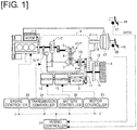
- FIG. 1 is a schematic system view illustrating the drive system of the hybrid vehicle drive device and the overall control system thereof of the first embodiment.
- the hybrid vehicle of FIG. 1 is mounted with an engine 1 and an electric motor 2 as the power source, and the engine 1 is started by a starter motor 3.
- the engine 1 is drivably coupled to drive wheels 5 via a V-belt-type continuously variable transmission 4, which is capable of being appropriately detachable, and the continuously variable transmission 4 is configured so that the outline is as described in the following explanation.
- the continuously variable transmission 4 is a continuously variable transmission CVT that is configured from a primary pulley 6, a secondary pulley 7, and a V-belt 8 that is bridged between these pulleys 6, 7.
- the primary pulley 6 is coupled to a crankshaft, which is an output shaft of the engine 1 via a torque converter T/C with a lockup clutch;
- the secondary pulley 7 is coupled to the drive wheels 5 sequentially via a clutch CL, a final gear set 9, and a differential mechanism 32 of a final reduction gear device 30 (refer to FIG. 2 ).
- the final gear set 9 refers to the meshing between a first gear 9a that is coupled to an output shaft of the clutch CL and a final reduction gear 31 of the final reduction gear device 30.
- An electric motor 2 is constantly coupled to the drive wheels 5 via a power transmission mechanism 11, and this electric motor 2 is driven via an inverter 13 by power from a battery 12.
- the power transmission mechanism 11 refers to the meshing among a second gear 11a (a rotary element) that is coupled to an output shaft of the electric motor 2, a third gear 1 lb that meshes with the second gear 1 1a, and a final reduction gear 31 that meshes with a fourth gear 11c, which meshes with the third gear 11b and the final reduction gear 31.
- the inverter 13 provides DC power from the battery 12 to the electric motor 2 after converting the DC power to AC power and controls the drive force and the rotational direction of the electric motor 2 by adjusting the power supplied to the electric motor 2.
- the electric motor 2 also functions as a generator, which is also provided for use in regenerative braking as described below.
- the inverter 13 causes the electric motor 2 to act as a generator by applying a generator load for regenerative braking to the electric motor 2, and the electric power generated by the electric motor 2 is stored in the battery 12.
- the clutch CL In the EV traveling state described above, if the clutch CL is engaged at the same time as the engine 1 is started with the starter motor 3, the power from the engine 1 will reach the drive wheels 5 sequentially via the torque converter T/C, the primary pulley 6, the V-belt 8, the secondary pulley 7, the clutch CL, and the final gear set 9, and the hybrid vehicle will travel in a hybrid traveling mode (HEV mode) via the engine 1 and the electric motor 2.
- HEV mode hybrid traveling mode
- the objective is achieved by clamping and braking a brake disk 14 that rotates with the drive wheels 5 with a caliper 15.
- the caliper 15 is connected to a master cylinder 18 that outputs a brake fluid pressure corresponding to the brake pedal stepping force under boost by a negative pressure-type brake booster 17 in response to the stepping force on a brake pedal 16, which a driver steps on; braking of the brake disk 14 is carried out by operating the caliper 15 with this brake fluid pressure.
- the wheels 5 are driven by a torque corresponding to a drive force command, which occurs when the driver steps on an accelerator pedal 19, and the hybrid vehicle is made to travel with a drive force corresponding to the needs of the driver.
- the traveling mode selection of the hybrid vehicle, the output control of the engine 1, the rotational direction control of the electric motor 2, the shift control of the continuously variable transmission 4, the engagement and disengagement control of the clutch CL, and the charge/discharge control of the battery 12 are all carried out by a hybrid controller 21.
- the hybrid controller 21 carries out these controls via a corresponding engine controller 22, a motor controller 23, a transmission controller 24, and a battery controller 25.
- a signal from a brake switch 26, which is a switch that is normally on and that switches from OFF to ON when braking by stepping on the brake pedal 16, and a signal from an accelerator opening sensor 27, which detects the accelerator pedal depression amount (the accelerator opening) APO, are input to the hybrid controller 21.
- the hybrid controller 21 further exchanges internal information among the engine controller 22, the motor controller 23, the transmission controller 24, and the battery controller 25.
- the engine controller 22 controls the output of the engine 1 in response to a command from the hybrid controller 21, and the motor controller 23 controls the rotational direction and the output of the electric motor 2 via the inverter 13 in response to a command from the hybrid controller 21.
- the transmission controller 24 controls the shifting of the continuously variable transmission 4 (a V-belt-type continuously variable transmission CVT) and the engagement/disengagement of the clutch CL with oil from an engine-driven oil pump O/P as a medium in response to a command from the hybrid controller 21.
- the battery controller 25 controls the charging/discharging of the battery 12 in response to a command from the hybrid controller 21.
- FIG. 2 is a schematic view showing the laid out configuration of the hybrid vehicle drive device of the first embodiment.
- the engine 1 and the electric motor 2 are disposed so that the crankshaft of the engine 1 and the rotating shaft of the electric motor are parallel, and both are mounted on a mounting surface 50a of a transaxle case 50.
- the engine 1 and the electric motor 2 are assembled so as to protrude from a substantially same plane of the mounting surface 50a.
- the torque converter T/C, the continuously variable transmission 4, the clutch CL, the first gear 9a, the final reduction gear device 30, and the power transmission mechanism 11 are housed in the transaxle case 50.
- An engine exhaust pipe (or an intake pipe) 1a is provided to a portion on the opposite side of the mounting surface 50a side of the engine 1.
- a drive shaft 33 is coupled below the transaxle case 50.
- the electric motor 2 is provided in a region sandwiched between the drive shaft 33 and the engine 1, as viewed from the radial direction, and is provided in a region sandwiched between the mounting surface 50a and the engine exhaust pipe 1a, as viewed from the axial direction.
- first gear 9a and the fourth gear 11c are shown as being side by side; however, in actuality, both the first gear 9a and the fourth gear 11c mesh with the final reduction gear 31 on the same plane in a direction perpendicular to the rotational axis of the final reduction gear 31, as shown in FIG. 3 .
- a control valve unit 40 that controls the hydraulic pressure necessary for shifting is provided to the continuously variable transmission 4 (refer to FIG. 3 ).
- a manual valve (not diagrammed) that operates in accordance with the position range of a shift lever 44, which is operated by the driver, is housed in the control valve unit 40.
- the manual valve interlocks with a manual shaft 41 that extends outside of the transaxle case 50.
- a selection lever 42 that extends in the radial direction, with the manual shaft 41 as the center, is mounted on the outside upper part of the transaxle case 50 of the manual shaft 41.
- shift cable 43 is attached to an end of the selection lever 42 on the opposite side of the manual shaft 41, and a shift lever 44, which is operated by the driver, is attached to the other end of the shift cable 43.
- a wire passes through the inside of the cylindrical outer tube of the shift cable 43; when the outer tube and the wire are moved relatively by the shift lever 44, the selection lever 42 revolves in response to the relative movement. Revolving the manual shaft 41 is thereby carried out, and the manual valve moves to a position corresponding to the shift lever 44.
- the routing of the shift cable 43 will be described below.
- FIG. 3 is a schematic view of the hybrid vehicle drive device of the first embodiment in a vehicle-mounted state, as viewed from the crankshaft side.
- the power transmission mechanism 11 is configured by the second, third, and fourth gears 11a, 11b, 11c and is disposed so that the second gear 11a is distanced from the drive shaft 33.
- the inter-axial distance between the drive shaft 33 and the second gear 11a is disposed in a position to be greater than the inter-axial distance between the drive shaft 33 and the first gear 9a.
- the electric motor 2 is connected to the second gear 11a, and the inter-axial distance between the rotating shaft of the electric motor 2 and the drive shaft 33 is secured; the power transmission mechanism 11 allows the size of the outer diameter of the electric motor 2 to be increased.
- the power transmission mechanism 11 is configured to be a mechanism having a gear with two or more axes, so that the distance between the drive shaft 33 and the rotating shaft of the electric motor 2 can be increased efficiently. Since the power transmission mechanism 11 is a deceleration mechanism, amplifying the torque of the electric motor 2 is possible, which facilitates the ability to secure the drive force at starting time and to secure the drive force during acceleration that is necessary for a vehicle.
- the electric motor 2 is disposed above the rotational axis of the drive shaft 33 with the transaxle case 50 in a vehicle-mounted state.
- the rotational axis of the drive shaft 33 is disposed in a position overlapping the projection plane of the electric motor 2 below the vehicle. That is, when securing the inter-axial distance of the drive shaft 33 and the rotating shaft of the electric motor 33 using the power transmission mechanism 11, reducing the overall size of the drive device, as viewed from the top surface of the vehicle, by disposing this device above the drive shaft 2 becomes possible, and providing an overall compact drive device, even if the size of the electric motor 2 is increased, is possible.
- FIG. 4 is a partially enlarged cross-sectional view of the portion accommodating the power transmission mechanism in the hybrid vehicle drive device of the first embodiment.
- the transaxle case 50 is configured by a converter housing 51 that houses the torque converter T/C, a transmission case 51 that houses the continuously variable transmission 52, and a middle wall 53 that separates the converter housing 4 from the transmission case 52. These configurations are installed by, first, fixing the middle wall 53 to the converter housing 51 with a bolt, then fixing the converter housing 51 to the transmission case 52, to which the middle wall 53 is attached.
- the second, third, and fourth gears 11a, 11b, 11c, which configure the power transmission mechanism 11, are accommodated between the converter housing 51 and the middle wall 53.
- mounting the electric motor 2 without providing a deceleration mechanism, etc., on the mounting surface 50a side becomes possible, and the axial direction dimensions of the electric motor 2 can be increased in size by securing a space between the engine exhaust pipe 1a and the mounting surface 50a.
- the converter housing 51 comprises a rib 51a on the mounting surface side 50a.
- the generation of radiated noise can thereby be suppressed by holding the power transmission mechanism 11 with the converter housing 51, even if vibration accompanying an increase in the rotational speed occurs, since the converter housing 51 is reinforced.
- the hybrid vehicle drive device of the embodiment is a front-engine, front-wheel drive system that has a transverse engine 1, and the transaxle case 50 is connected to the output side of the engine 1; as a result, the manual shaft 41 and the selection lever 42 are in positions that are slightly offset to one side (the left side in FIG. 2 ) from the center of the vehicle width direction.
- the shift lever 44 since the shift lever 44 is set to be substantially near the center of the vehicle width direction, the shift cable 43, which connects the shift lever 44 and the selection lever 42, is routed in a slightly curved manner, as illustrated in FIG. 2 .
- the power transmission mechanism 11 is provided in a region of the transaxle case 50 that expands radially outward in consideration of assembling property, etc.
- the shift cable 43 is connected to the selection lever 42 through the vicinity of the transmission case 52, which is the side wall of the portion to which the power transmission mechanism 11 is provided (refer to FIG. 4 ).
- the second gear 11a which is connected to the electric motor 2
- a high-speed rotation tends to occur, and radiated noise is likely generated; as a result, there is the risk that vibration performance cannot be secured.
- gears were combined as the power transmission mechanism 11; however, the power transmission mechanism is not limited to gears and can be configured from a chain and a sprocket. Also, an example was described in the embodiment in which the first gear 9a and the final reduction gear 31 are meshed, and the power transmission mechanism 11 and the final reduction gear 31 are meshed; however, the power transmission mechanism 11 and the first gear 9a may also be meshed.
- an example was described in the embodiment, in which an electric motor 2 of a hybrid vehicle is mounted; however, the present invention can also be applied when mounting a large generator that supplies a drive current to a motor provided to another wheel. Also, an example of an electric motor was described, but the present invention can be applied when providing a transfer as a four-wheel drive unit.
- a continuously variable transmission 4 is mounted; however, the present invention is not limited to a continuously variable transmission 4 and may be another, stepped transmission.
- a planetary gear mechanism comprising a plurality of frictional engagement elements can be mounted in place of the clutch CL, and a sub-transmission that is able to appropriately shift gears can be also mounted.
Landscapes
- Engineering & Computer Science (AREA)
- Mechanical Engineering (AREA)
- Chemical & Material Sciences (AREA)
- Combustion & Propulsion (AREA)
- Transportation (AREA)
- General Engineering & Computer Science (AREA)
- Hybrid Electric Vehicles (AREA)
- Arrangement Of Transmissions (AREA)
- General Details Of Gearings (AREA)
- Electric Propulsion And Braking For Vehicles (AREA)
Description
- The present invention relates to a hybrid vehicle drive device equipped with an engine and an electric motor.
- For example, a hybrid vehicle drive device, such as that disclosed in
Patent Document 1, has been known. In this vehicle, a first electric motor 10 is coupled to an output shaft 17a via anelectric motor transmission 17. Theelectric motor transmission 17 is configured from planetary gears, and the first electric motor 10, the output shaft 17a, and theelectric motor transmission 17 are arranged in one row in the axial direction. - Patent Document 1: Patent No.
3,584,680 - Document
JPH10341503 - The rotational speed in the
electric motor transmission 17, especially of the rotary element that is connected with a first electric motor 10, tends to become a high-speed rotation, and radiated noise is likely generated if this is carelessly installed in a transaxle case; as a result, there is the risk that the vibration performance cannot be secured. - In light of the problem described above, an object of the present invention is to provide a hybrid vehicle drive device that is able to avoid a deterioration in the vibration performance caused by a power transmission mechanism that transmits the rotation of an electric motor to the drive wheels.
- For this purpose, this hybrid vehicle drive device is provided with a transmission coupled to the engine output shaft of an engine, a final reduction gear coupled to the transmission output shaft of the transmission, a drive shaft coupled to the final reduction gear, and a power transmission mechanism that transmits the rotation of an electric motor to the final reduction gear. The hybrid vehicle drive device is provided with a transaxle case that accommodates the transmission, the final reduction gear and the power transmission mechanism and that has a mounting surface for mounting the engine and the electric motor. Additionally, the transaxle case is configured from an engine-side converter housing, a transmission-side transmission case, and a middle wall attached to the converter housing, which separates the converter housing from the transmission case, wherein the power transmission mechanism is housed between the converter housing and the middle wall.
- In other words, with the power transmission mechanism being housed between the converter housing and the middle wall, the power transmission mechanism will not be supported by the transmission case, and avoiding a deterioration in the vibration performance caused by the power transmission mechanism becomes possible.
-
-
FIG. 1 is a schematic system view illustrating the drive system of the hybrid vehicle drive device and the overall control system thereof of the first embodiment. -
FIG. 2 is a schematic view showing the laid out configuration of the hybrid vehicle drive device of the first embodiment. -
FIG. 3 is a schematic view of the hybrid vehicle drive device of the first embodiment in a vehicle-mounted state as viewed from the crankshaft side. -
FIG. 4 is a partially enlarged cross-sectional view of the portion accommodating the power transmission mechanism in the hybrid vehicle drive device of the first embodiment. -
- 1
- Engine
- 1a
- Engine exhaust pipe
- 2
- Electric motor (electric motor)
- 4
- V-belt-type continuously variable transmission
- 5
- Drive wheel
- 9a
- First gear
- 11
- Power transmission mechanism
- 11a
- Second gear
- 30
- Final reduction gear device
- 31
- Final reduction gear
- 33
- Drive shaft
- 40
- Control valve unit
- 50
- Transaxle case
- 51
- Converter housing
- 52
- Transmission case
- 53
- Middle wall
- 50a
- Mounting surface
- 51a
- Rib
- CL
- Clutch
-
FIG. 1 is a schematic system view illustrating the drive system of the hybrid vehicle drive device and the overall control system thereof of the first embodiment. The hybrid vehicle ofFIG. 1 is mounted with anengine 1 and anelectric motor 2 as the power source, and theengine 1 is started by a starter motor 3. Theengine 1 is drivably coupled to drivewheels 5 via a V-belt-type continuouslyvariable transmission 4, which is capable of being appropriately detachable, and the continuouslyvariable transmission 4 is configured so that the outline is as described in the following explanation. - The continuously
variable transmission 4 is a continuously variable transmission CVT that is configured from a primary pulley 6, a secondary pulley 7, and a V-belt 8 that is bridged between these pulleys 6, 7. The primary pulley 6 is coupled to a crankshaft, which is an output shaft of theengine 1 via a torque converter T/C with a lockup clutch; the secondary pulley 7 is coupled to thedrive wheels 5 sequentially via a clutch CL, a final gear set 9, and adifferential mechanism 32 of a final reduction gear device 30 (refer toFIG. 2 ). Here, the final gear set 9 refers to the meshing between afirst gear 9a that is coupled to an output shaft of the clutch CL and afinal reduction gear 31 of the finalreduction gear device 30. - Thus, in an engaged state of the clutch CL, power from the
engine 1 is input to the primary pulley 6 via the torque converter T/C; reaches thedrive wheels 5 via the V-belt 8, the secondary pulley 7, the clutch CL, and the final gear set 9 sequentially; and is provided to the traveling hybrid vehicle. - An
electric motor 2 is constantly coupled to thedrive wheels 5 via apower transmission mechanism 11, and thiselectric motor 2 is driven via aninverter 13 by power from abattery 12. Here, thepower transmission mechanism 11 refers to the meshing among asecond gear 11a (a rotary element) that is coupled to an output shaft of theelectric motor 2, athird gear 1 lb that meshes with thesecond gear 1 1a, and afinal reduction gear 31 that meshes with afourth gear 11c, which meshes with thethird gear 11b and thefinal reduction gear 31. - The
inverter 13 provides DC power from thebattery 12 to theelectric motor 2 after converting the DC power to AC power and controls the drive force and the rotational direction of theelectric motor 2 by adjusting the power supplied to theelectric motor 2. - In addition to the motor driving described above, the
electric motor 2 also functions as a generator, which is also provided for use in regenerative braking as described below. During this regenerative braking, theinverter 13 causes theelectric motor 2 to act as a generator by applying a generator load for regenerative braking to theelectric motor 2, and the electric power generated by theelectric motor 2 is stored in thebattery 12. - In the hybrid vehicle of the first embodiment, only the power of the
electric motor 2 reaches thedrive wheels 5 via thepower transmission mechanism 11 by driving theelectric motor 2 in a state in which the clutch CL is released and theengine 1 is stopped in order to conduct traveling in an electric traveling mode (EV mode) with only theelectric motor 2. During this time, theengine 1, which is in a stopped state, will not be dragged and rotated, and wasteful power consumption during EV traveling is suppressed by having the clutch CL released. - In the EV traveling state described above, if the clutch CL is engaged at the same time as the
engine 1 is started with the starter motor 3, the power from theengine 1 will reach thedrive wheels 5 sequentially via the torque converter T/C, the primary pulley 6, the V-belt 8, the secondary pulley 7, the clutch CL, and the final gear set 9, and the hybrid vehicle will travel in a hybrid traveling mode (HEV mode) via theengine 1 and theelectric motor 2. - To stop a hybrid vehicle that is in the above-described traveling state or to maintain this stopped state, the objective is achieved by clamping and braking a
brake disk 14 that rotates with thedrive wheels 5 with acaliper 15. Thecaliper 15 is connected to a master cylinder 18 that outputs a brake fluid pressure corresponding to the brake pedal stepping force under boost by a negative pressure-type brake booster 17 in response to the stepping force on abrake pedal 16, which a driver steps on; braking of thebrake disk 14 is carried out by operating thecaliper 15 with this brake fluid pressure. In both the EV mode and the HEV mode, thewheels 5 are driven by a torque corresponding to a drive force command, which occurs when the driver steps on anaccelerator pedal 19, and the hybrid vehicle is made to travel with a drive force corresponding to the needs of the driver. - The traveling mode selection of the hybrid vehicle, the output control of the
engine 1, the rotational direction control of theelectric motor 2, the shift control of the continuouslyvariable transmission 4, the engagement and disengagement control of the clutch CL, and the charge/discharge control of thebattery 12 are all carried out by ahybrid controller 21. At this time, thehybrid controller 21 carries out these controls via a correspondingengine controller 22, amotor controller 23, atransmission controller 24, and abattery controller 25. - Accordingly, a signal from a
brake switch 26, which is a switch that is normally on and that switches from OFF to ON when braking by stepping on thebrake pedal 16, and a signal from anaccelerator opening sensor 27, which detects the accelerator pedal depression amount (the accelerator opening) APO, are input to thehybrid controller 21. Thehybrid controller 21 further exchanges internal information among theengine controller 22, themotor controller 23, thetransmission controller 24, and thebattery controller 25. - The
engine controller 22 controls the output of theengine 1 in response to a command from thehybrid controller 21, and themotor controller 23 controls the rotational direction and the output of theelectric motor 2 via theinverter 13 in response to a command from thehybrid controller 21. Thetransmission controller 24 controls the shifting of the continuously variable transmission 4 (a V-belt-type continuously variable transmission CVT) and the engagement/disengagement of the clutch CL with oil from an engine-driven oil pump O/P as a medium in response to a command from thehybrid controller 21. Thebattery controller 25 controls the charging/discharging of thebattery 12 in response to a command from thehybrid controller 21. -
FIG. 2 is a schematic view showing the laid out configuration of the hybrid vehicle drive device of the first embodiment. Theengine 1 and theelectric motor 2 are disposed so that the crankshaft of theengine 1 and the rotating shaft of the electric motor are parallel, and both are mounted on a mountingsurface 50a of atransaxle case 50. In other words, theengine 1 and theelectric motor 2 are assembled so as to protrude from a substantially same plane of the mountingsurface 50a. The torque converter T/C, the continuouslyvariable transmission 4, the clutch CL, thefirst gear 9a, the finalreduction gear device 30, and thepower transmission mechanism 11 are housed in thetransaxle case 50. - An engine exhaust pipe (or an intake pipe) 1a is provided to a portion on the opposite side of the mounting
surface 50a side of theengine 1. Adrive shaft 33 is coupled below thetransaxle case 50. Thus, theelectric motor 2 is provided in a region sandwiched between thedrive shaft 33 and theengine 1, as viewed from the radial direction, and is provided in a region sandwiched between the mountingsurface 50a and the engine exhaust pipe 1a, as viewed from the axial direction. - To facilitate the depiction in
FIG. 2 , thefirst gear 9a and thefourth gear 11c are shown as being side by side; however, in actuality, both thefirst gear 9a and thefourth gear 11c mesh with thefinal reduction gear 31 on the same plane in a direction perpendicular to the rotational axis of thefinal reduction gear 31, as shown inFIG. 3 . - A
control valve unit 40 that controls the hydraulic pressure necessary for shifting is provided to the continuously variable transmission 4 (refer toFIG. 3 ). A manual valve (not diagrammed) that operates in accordance with the position range of ashift lever 44, which is operated by the driver, is housed in thecontrol valve unit 40. The manual valve interlocks with amanual shaft 41 that extends outside of thetransaxle case 50. Aselection lever 42 that extends in the radial direction, with themanual shaft 41 as the center, is mounted on the outside upper part of thetransaxle case 50 of themanual shaft 41. One end of ashift cable 43 is attached to an end of theselection lever 42 on the opposite side of themanual shaft 41, and ashift lever 44, which is operated by the driver, is attached to the other end of theshift cable 43. A wire passes through the inside of the cylindrical outer tube of theshift cable 43; when the outer tube and the wire are moved relatively by theshift lever 44, theselection lever 42 revolves in response to the relative movement. Revolving themanual shaft 41 is thereby carried out, and the manual valve moves to a position corresponding to theshift lever 44. The routing of theshift cable 43 will be described below. -
FIG. 3 is a schematic view of the hybrid vehicle drive device of the first embodiment in a vehicle-mounted state, as viewed from the crankshaft side. Thepower transmission mechanism 11 is configured by the second, third, andfourth gears second gear 11a is distanced from thedrive shaft 33. In other words, the inter-axial distance between thedrive shaft 33 and thesecond gear 11a is disposed in a position to be greater than the inter-axial distance between thedrive shaft 33 and thefirst gear 9a. Theelectric motor 2 is connected to thesecond gear 11a, and the inter-axial distance between the rotating shaft of theelectric motor 2 and thedrive shaft 33 is secured; thepower transmission mechanism 11 allows the size of the outer diameter of theelectric motor 2 to be increased. - In the first embodiment, the
power transmission mechanism 11 is configured to be a mechanism having a gear with two or more axes, so that the distance between thedrive shaft 33 and the rotating shaft of theelectric motor 2 can be increased efficiently. Since thepower transmission mechanism 11 is a deceleration mechanism, amplifying the torque of theelectric motor 2 is possible, which facilitates the ability to secure the drive force at starting time and to secure the drive force during acceleration that is necessary for a vehicle. - The
electric motor 2 is disposed above the rotational axis of thedrive shaft 33 with thetransaxle case 50 in a vehicle-mounted state. In other words, as viewed from the top surface of the vehicle, the rotational axis of thedrive shaft 33 is disposed in a position overlapping the projection plane of theelectric motor 2 below the vehicle. That is, when securing the inter-axial distance of thedrive shaft 33 and the rotating shaft of theelectric motor 33 using thepower transmission mechanism 11, reducing the overall size of the drive device, as viewed from the top surface of the vehicle, by disposing this device above thedrive shaft 2 becomes possible, and providing an overall compact drive device, even if the size of theelectric motor 2 is increased, is possible. -
FIG. 4 is a partially enlarged cross-sectional view of the portion accommodating the power transmission mechanism in the hybrid vehicle drive device of the first embodiment. Thetransaxle case 50 is configured by aconverter housing 51 that houses the torque converter T/C, atransmission case 51 that houses the continuouslyvariable transmission 52, and amiddle wall 53 that separates theconverter housing 4 from thetransmission case 52. These configurations are installed by, first, fixing themiddle wall 53 to theconverter housing 51 with a bolt, then fixing theconverter housing 51 to thetransmission case 52, to which themiddle wall 53 is attached. - The second, third, and
fourth gears power transmission mechanism 11, are accommodated between theconverter housing 51 and themiddle wall 53. As a result, mounting theelectric motor 2 without providing a deceleration mechanism, etc., on the mountingsurface 50a side becomes possible, and the axial direction dimensions of theelectric motor 2 can be increased in size by securing a space between the engine exhaust pipe 1a and the mountingsurface 50a. - In this manner, ease of assembly is ensured by dividing and configuring the
transaxle case 50 from theconverter housing 51, which is on the engine side, and thetransmission case 52, which is on the transmission side. In other words, when considering the ease of assembly, disposing thepower transmission mechanism 11 in a part that can be divided into theconverter housing 51 and thetransmission case 52 is advantageous. - The
converter housing 51 comprises arib 51a on the mountingsurface side 50a. The generation of radiated noise can thereby be suppressed by holding thepower transmission mechanism 11 with theconverter housing 51, even if vibration accompanying an increase in the rotational speed occurs, since theconverter housing 51 is reinforced. - Next, the routing of the
shift cable 43 will be described. As illustrated inFIG. 2 , the hybrid vehicle drive device of the embodiment is a front-engine, front-wheel drive system that has atransverse engine 1, and thetransaxle case 50 is connected to the output side of theengine 1; as a result, themanual shaft 41 and theselection lever 42 are in positions that are slightly offset to one side (the left side inFIG. 2 ) from the center of the vehicle width direction. On the other hand, since theshift lever 44 is set to be substantially near the center of the vehicle width direction, theshift cable 43, which connects theshift lever 44 and theselection lever 42, is routed in a slightly curved manner, as illustrated inFIG. 2 . At this time, since a wire moves relatively inside of the outer tube of theshift cable 43, as described above, if theshift cable 43 is substantially curved, the friction will increase, or smooth operation will be interrupted; therefore, the connection should be made with as little curvature as possible. - As illustrated in
FIG. 3 , thepower transmission mechanism 11 is provided in a region of thetransaxle case 50 that expands radially outward in consideration of assembling property, etc. Thus, theshift cable 43 is connected to theselection lever 42 through the vicinity of thetransmission case 52, which is the side wall of the portion to which thepower transmission mechanism 11 is provided (refer toFIG. 4 ). At this time, if each rotary element of thepower transmission mechanism 11 were to be held between thetransmission case 52 and theconverter housing 51 without using amiddle wall 53, especially thesecond gear 11a, which is connected to theelectric motor 2, a high-speed rotation tends to occur, and radiated noise is likely generated; as a result, there is the risk that vibration performance cannot be secured. - In relation to this problem, securing the thickness or providing a rib is conceivable in order to secure the strength of the
transmission case 52. However, curving theshift cable 43 as little as possible is desirable; as a result, if thetransmission case 52 is reinforced, etc., thetransmission case 52 will expand in the rotational axis direction, and the curvature theshift cable 43 will be increased, making an appropriate routing difficult. - Therefore, in the embodiment, a
middle wall 53 that is attached to theconverter housing 51, rather than to thetransmission case 52, is provided; by housing thepower transmission mechanism 11 with thisconverter housing 51 and themiddle wall 53, the curvature of theshift cable 43 is suppressed, and the vibration performance is secured. - As described above, the effects listed below can be obtained with the first embodiment.
- (1) The present invention comprises: a continuously variable transmission 4 (a transmission) that is coupled to an engine output shaft of an
engine 1;
afinal reduction gear 31 that is coupled to a transmission output shaft of the continuouslyvariable transmission 4;
adrive shaft 33 that is coupled to thefinal reduction gear 31;
apower transmission mechanism 11 that transmits the rotation of the electric motor 2 (an electric motor) to thefinal reduction gear 31; and
atransaxle case 50 that houses the continuouslyvariable transmission 4, thefinal reduction gear 31, and thepower transmission mechanism 11 and that has a mountingsurface 50a for mounting theengine 1 and the electric motor 2a;
wherein
thetransaxle case 50 is configured by an engine-side converter housing 51, a continuously variable transmission-side transmission case 52, and amiddle wall 53 that is attached to theconverter housing 51 and that separates the converter housing from thetransmission case 52, and
thepower transmission mechanism 11 is housed between theconverter housing 51 and themiddle wall 53.
In other words, with thepower transmission mechanism 11 being housed between theconverter housing 51 and themiddle wall 53, thepower transmission mechanism 11 will not be supported by thetransmission case 52, and avoiding a deterioration in the vibration performance caused by thepower transmission mechanism 11 becomes possible. - (2) The
transaxle case 50 comprises arib 51a on the mountingsurface 50a. The generation of radiated noise can thereby be suppressed by holding thepower transmission mechanism 11 with theconverter housing 51, even if a vibration accompanying an increase in the rotational speed occurs, since theconverter housing 51 is reinforced.
The present invention was described above based on each embodiment; however, the invention is not limited to the configurations described above, and other configurations are included in the present invention. - For example, an example was described in the embodiment, in which gears were combined as the
power transmission mechanism 11; however, the power transmission mechanism is not limited to gears and can be configured from a chain and a sprocket. Also, an example was described in the embodiment in which thefirst gear 9a and thefinal reduction gear 31 are meshed, and thepower transmission mechanism 11 and thefinal reduction gear 31 are meshed; however, thepower transmission mechanism 11 and thefirst gear 9a may also be meshed. - Additionally, an example was described in the embodiment, in which an
electric motor 2 of a hybrid vehicle is mounted; however, the present invention can also be applied when mounting a large generator that supplies a drive current to a motor provided to another wheel. Also, an example of an electric motor was described, but the present invention can be applied when providing a transfer as a four-wheel drive unit. - In the hybrid vehicle of the first embodiment, an example was described in which a continuously
variable transmission 4 is mounted; however, the present invention is not limited to a continuouslyvariable transmission 4 and may be another, stepped transmission. A planetary gear mechanism comprising a plurality of frictional engagement elements can be mounted in place of the clutch CL, and a sub-transmission that is able to appropriately shift gears can be also mounted. - Furthermore, a configuration was described in the embodiment, in which the engine is restarted by a starter motor 3, but other configurations are also possible. Specifically, in recent years, a technology has been put into practical use, in which the alternator is replaced with a motor generator in a vehicle with an idling stop function, and an alternator function is added to this motor generator to add an engine starting function; as a result, restarting the engine is carried out from an idling stop by this motor generator, rather than the starter motor. The present invention may be configured so that restarting the engine is carried out by a motor generator described above.
Claims (2)
- A hybrid vehicle drive device, comprising:a transmission (4) that is coupled to an engine output shaft of an engine (1);a final reduction gear (31) that is coupled to a transmission output shaft of the transmission (4);a drive shaft that is coupled to the final reduction gear (31);a power transmission mechanism (11) that transmits the rotation of an electric motor (2) to the final reduction gear (31); anda transaxle case (50) that accommodates the transmission (4), the final reduction gear (31) and the power transmission mechanism (11) and that has a mounting surface (50a) for mounting the engine (1) and the electric motor (2);characterized in thatthe transaxle case (50) is configured by an engine-side converter housing (51), a transmission-side transmission case (52), and a middle wall (53) that is attached to the converter housing (51) and separates the converter housing (51) from the transmission case (52), andthe power transmission mechanism (11) is housed between the converter housing (51) and the transmission case (52).
- The hybrid vehicle drive device recited in claim 1, wherein
the transaxle case (50) comprises a rib (51a) on the mounting surface (50a).
Applications Claiming Priority (2)
| Application Number | Priority Date | Filing Date | Title |
|---|---|---|---|
| JP2012278932 | 2012-12-21 | ||
| PCT/JP2013/080682 WO2014097781A1 (en) | 2012-12-21 | 2013-11-13 | Hybrid vehicle drive device |
Publications (3)
| Publication Number | Publication Date |
|---|---|
| EP2937238A1 EP2937238A1 (en) | 2015-10-28 |
| EP2937238A4 EP2937238A4 (en) | 2017-04-05 |
| EP2937238B1 true EP2937238B1 (en) | 2021-03-24 |
Family
ID=50978125
Family Applications (1)
| Application Number | Title | Priority Date | Filing Date |
|---|---|---|---|
| EP13865470.2A Not-in-force EP2937238B1 (en) | 2012-12-21 | 2013-11-13 | Hybrid vehicle drive device |
Country Status (5)
| Country | Link |
|---|---|
| US (1) | US9840141B2 (en) |
| EP (1) | EP2937238B1 (en) |
| JP (1) | JP5859143B2 (en) |
| CN (1) | CN104870229B (en) |
| WO (1) | WO2014097781A1 (en) |
Families Citing this family (9)
| Publication number | Priority date | Publication date | Assignee | Title |
|---|---|---|---|---|
| JP6390547B2 (en) * | 2015-08-07 | 2018-09-19 | 株式会社デンソー | Vehicle drive device |
| WO2017193130A1 (en) * | 2016-05-06 | 2017-11-09 | Axletech International Ip Holdings, Llc | Axle assembly with electric motor |
| US10173514B2 (en) * | 2016-11-01 | 2019-01-08 | GM Global Technology Operations LLC | Planetary axis transfer gearbox |
| KR102488782B1 (en) * | 2017-08-21 | 2023-01-16 | 엘지이노텍 주식회사 | Gearbox and actuator having the same |
| FR3075699B1 (en) * | 2017-12-22 | 2019-11-22 | Renault S.A.S. | ELECTRIC MOTOR SUPPORT COMPRISING AN INTEGRATED CONDUIT AND MOTOR POWER PACK COMPRISING SUCH A SUPPORT |
| JP7211928B2 (en) * | 2019-12-04 | 2023-01-24 | 株式会社クボタ | multipurpose vehicle |
| JP7168545B2 (en) * | 2019-12-19 | 2022-11-09 | 株式会社クボタ | multipurpose vehicle |
| CN114475209B (en) * | 2020-10-23 | 2023-07-25 | 上海汽车集团股份有限公司 | Hybrid power system and automobile |
| WO2024054986A1 (en) | 2022-09-08 | 2024-03-14 | Harbinger Motors Inc. | Electric commercial vehicle drive unit |
Family Cites Families (16)
| Publication number | Priority date | Publication date | Assignee | Title |
|---|---|---|---|---|
| US3584680A (en) | 1969-11-03 | 1971-06-15 | Mead Corp | Hollow green sand cores |
| JPS585558A (en) * | 1981-06-29 | 1983-01-12 | Aisin Warner Ltd | Case for vehicular multiple-stage automatic speed change gear |
| US5558595A (en) * | 1995-02-17 | 1996-09-24 | General Motors Corporation | One-mode, input-split, parallel, hybrid transmission |
| JP3168895B2 (en) * | 1995-12-06 | 2001-05-21 | トヨタ自動車株式会社 | Hybrid drive |
| US6155364A (en) * | 1996-02-21 | 2000-12-05 | Toyota Jidosha Kabushiki Kaisha | Hybrid drive system wherein planetary gear mechanism is disposed radially inwardly of stator coil of motor/generator |
| JP3584680B2 (en) | 1997-06-06 | 2004-11-04 | 日産自動車株式会社 | Hybrid vehicle drive system of internal combustion engine and electric motor |
| US6332257B1 (en) * | 1999-04-30 | 2001-12-25 | Chrysler Corporation | Method of converting an existing vehicle powertrain to a hybrid powertrain system |
| JP3832465B2 (en) * | 2003-10-27 | 2006-10-11 | トヨタ自動車株式会社 | Hybrid vehicle drive system |
| JP2005153691A (en) * | 2003-11-26 | 2005-06-16 | Aisin Seiki Co Ltd | Driving mechanism for vehicle |
| JP4712395B2 (en) * | 2005-01-06 | 2011-06-29 | 住友重機械工業株式会社 | Gear box |
| JP2007205468A (en) * | 2006-02-01 | 2007-08-16 | Honda Motor Co Ltd | Reducer case structure |
| JP4823118B2 (en) * | 2007-03-29 | 2011-11-24 | ダイハツ工業株式会社 | Hybrid vehicle drive system |
| JP4875534B2 (en) * | 2007-04-18 | 2012-02-15 | トヨタ自動車株式会社 | Vehicle drive device |
| JP5218031B2 (en) * | 2008-12-25 | 2013-06-26 | トヨタ自動車株式会社 | Vehicle drive device |
| JP5375417B2 (en) | 2009-08-03 | 2013-12-25 | マツダ株式会社 | Vehicle drive device |
| CN103282227B (en) * | 2010-12-22 | 2015-12-16 | 丰田自动车株式会社 | Transmission device for vehicle |
-
2013
- 2013-11-13 JP JP2014553020A patent/JP5859143B2/en not_active Expired - Fee Related
- 2013-11-13 WO PCT/JP2013/080682 patent/WO2014097781A1/en active Application Filing
- 2013-11-13 EP EP13865470.2A patent/EP2937238B1/en not_active Not-in-force
- 2013-11-13 CN CN201380066195.3A patent/CN104870229B/en not_active Expired - Fee Related
- 2013-11-13 US US14/646,746 patent/US9840141B2/en active Active
Non-Patent Citations (1)
| Title |
|---|
| None * |
Also Published As
| Publication number | Publication date |
|---|---|
| CN104870229A (en) | 2015-08-26 |
| CN104870229B (en) | 2017-05-31 |
| JP5859143B2 (en) | 2016-02-10 |
| EP2937238A1 (en) | 2015-10-28 |
| US9840141B2 (en) | 2017-12-12 |
| EP2937238A4 (en) | 2017-04-05 |
| JPWO2014097781A1 (en) | 2017-01-12 |
| WO2014097781A1 (en) | 2014-06-26 |
| US20150306948A1 (en) | 2015-10-29 |
Similar Documents
| Publication | Publication Date | Title |
|---|---|---|
| EP2937238B1 (en) | Hybrid vehicle drive device | |
| EP2937237B1 (en) | Hybrid vehicle drive device | |
| JP3682964B2 (en) | Vehicle drive device | |
| JP6344358B2 (en) | Drive device for hybrid vehicle | |
| JP7053951B2 (en) | Power system for hybrid vehicles | |
| JP7011754B2 (en) | Hybrid vehicle transmission and power system | |
| US8485929B2 (en) | Motor vehicle power train | |
| US8758179B2 (en) | Electrically-variable transmission for a vehicle | |
| WO2011138892A1 (en) | Hybrid vehicle driving system | |
| US9193253B2 (en) | Power transmission system of hybrid electric vehicle | |
| JP2017177975A (en) | Hybrid vehicle system | |
| US9260001B2 (en) | Power transmission system of hybrid electric vehicle | |
| JP6817767B2 (en) | Control device and control method for hybrid vehicle system | |
| JP5024277B2 (en) | Installation method of motor for vehicle | |
| EP2694311A1 (en) | Multi-modal hybrid vehicle and connection device in a hybrid powertrain system | |
| WO2014119086A1 (en) | Drive device for hybrid vehicle | |
| JP2006306327A (en) | Hybrid drive unit for vehicle | |
| JP3855489B2 (en) | Vehicle drive device | |
| JP2007074833A (en) | Drive unit for hybrid vehicles | |
| JP2007302179A (en) | Control device of hybrid vehicle, and control method of hybrid vehicle | |
| JP3691720B2 (en) | Transmission unit | |
| JP6318799B2 (en) | In-vehicle oil pump drive switching device | |
| JP2004123060A (en) | Drive device of electric automobile | |
| JP3931809B2 (en) | Vehicle control device | |
| JP6269073B2 (en) | Hybrid vehicle |
Legal Events
| Date | Code | Title | Description |
|---|---|---|---|
| PUAI | Public reference made under article 153(3) epc to a published international application that has entered the european phase |
Free format text: ORIGINAL CODE: 0009012 |
|
| 17P | Request for examination filed |
Effective date: 20150714 |
|
| AK | Designated contracting states |
Kind code of ref document: A1 Designated state(s): AL AT BE BG CH CY CZ DE DK EE ES FI FR GB GR HR HU IE IS IT LI LT LU LV MC MK MT NL NO PL PT RO RS SE SI SK SM TR |
|
| AX | Request for extension of the european patent |
Extension state: BA ME |
|
| DAX | Request for extension of the european patent (deleted) | ||
| A4 | Supplementary search report drawn up and despatched |
Effective date: 20170302 |
|
| RIC1 | Information provided on ipc code assigned before grant |
Ipc: B60K 6/48 20071001ALI20170224BHEP Ipc: F16H 57/00 20120101ALI20170224BHEP Ipc: B60K 6/405 20071001ALI20170224BHEP Ipc: F16H 57/021 20120101ALI20170224BHEP Ipc: F16H 57/02 20120101ALI20170224BHEP Ipc: B60K 6/40 20071001ALI20170224BHEP Ipc: B60K 6/543 20071001ALI20170224BHEP Ipc: B60K 5/04 20060101ALI20170224BHEP Ipc: B60K 6/36 20071001AFI20170224BHEP |
|
| GRAP | Despatch of communication of intention to grant a patent |
Free format text: ORIGINAL CODE: EPIDOSNIGR1 |
|
| STAA | Information on the status of an ep patent application or granted ep patent |
Free format text: STATUS: GRANT OF PATENT IS INTENDED |
|
| INTG | Intention to grant announced |
Effective date: 20201210 |
|
| RIN1 | Information on inventor provided before grant (corrected) |
Inventor name: OKUDA TAKAYUKI Inventor name: OOKI SHINJIRO |
|
| GRAS | Grant fee paid |
Free format text: ORIGINAL CODE: EPIDOSNIGR3 |
|
| GRAA | (expected) grant |
Free format text: ORIGINAL CODE: 0009210 |
|
| STAA | Information on the status of an ep patent application or granted ep patent |
Free format text: STATUS: THE PATENT HAS BEEN GRANTED |
|
| AK | Designated contracting states |
Kind code of ref document: B1 Designated state(s): AL AT BE BG CH CY CZ DE DK EE ES FI FR GB GR HR HU IE IS IT LI LT LU LV MC MK MT NL NO PL PT RO RS SE SI SK SM TR |
|
| REG | Reference to a national code |
Ref country code: GB Ref legal event code: FG4D |
|
| REG | Reference to a national code |
Ref country code: CH Ref legal event code: EP |
|
| REG | Reference to a national code |
Ref country code: IE Ref legal event code: FG4D |
|
| REG | Reference to a national code |
Ref country code: AT Ref legal event code: REF Ref document number: 1374132 Country of ref document: AT Kind code of ref document: T Effective date: 20210415 Ref country code: DE Ref legal event code: R096 Ref document number: 602013076496 Country of ref document: DE |
|
| REG | Reference to a national code |
Ref country code: LT Ref legal event code: MG9D |
|
| PG25 | Lapsed in a contracting state [announced via postgrant information from national office to epo] |
Ref country code: FI Free format text: LAPSE BECAUSE OF FAILURE TO SUBMIT A TRANSLATION OF THE DESCRIPTION OR TO PAY THE FEE WITHIN THE PRESCRIBED TIME-LIMIT Effective date: 20210324 Ref country code: GR Free format text: LAPSE BECAUSE OF FAILURE TO SUBMIT A TRANSLATION OF THE DESCRIPTION OR TO PAY THE FEE WITHIN THE PRESCRIBED TIME-LIMIT Effective date: 20210625 Ref country code: HR Free format text: LAPSE BECAUSE OF FAILURE TO SUBMIT A TRANSLATION OF THE DESCRIPTION OR TO PAY THE FEE WITHIN THE PRESCRIBED TIME-LIMIT Effective date: 20210324 Ref country code: BG Free format text: LAPSE BECAUSE OF FAILURE TO SUBMIT A TRANSLATION OF THE DESCRIPTION OR TO PAY THE FEE WITHIN THE PRESCRIBED TIME-LIMIT Effective date: 20210624 Ref country code: NO Free format text: LAPSE BECAUSE OF FAILURE TO SUBMIT A TRANSLATION OF THE DESCRIPTION OR TO PAY THE FEE WITHIN THE PRESCRIBED TIME-LIMIT Effective date: 20210624 |
|
| PG25 | Lapsed in a contracting state [announced via postgrant information from national office to epo] |
Ref country code: SE Free format text: LAPSE BECAUSE OF FAILURE TO SUBMIT A TRANSLATION OF THE DESCRIPTION OR TO PAY THE FEE WITHIN THE PRESCRIBED TIME-LIMIT Effective date: 20210324 Ref country code: RS Free format text: LAPSE BECAUSE OF FAILURE TO SUBMIT A TRANSLATION OF THE DESCRIPTION OR TO PAY THE FEE WITHIN THE PRESCRIBED TIME-LIMIT Effective date: 20210324 Ref country code: LV Free format text: LAPSE BECAUSE OF FAILURE TO SUBMIT A TRANSLATION OF THE DESCRIPTION OR TO PAY THE FEE WITHIN THE PRESCRIBED TIME-LIMIT Effective date: 20210324 |
|
| REG | Reference to a national code |
Ref country code: NL Ref legal event code: MP Effective date: 20210324 |
|
| REG | Reference to a national code |
Ref country code: AT Ref legal event code: MK05 Ref document number: 1374132 Country of ref document: AT Kind code of ref document: T Effective date: 20210324 |
|
| PG25 | Lapsed in a contracting state [announced via postgrant information from national office to epo] |
Ref country code: NL Free format text: LAPSE BECAUSE OF FAILURE TO SUBMIT A TRANSLATION OF THE DESCRIPTION OR TO PAY THE FEE WITHIN THE PRESCRIBED TIME-LIMIT Effective date: 20210324 |
|
| PG25 | Lapsed in a contracting state [announced via postgrant information from national office to epo] |
Ref country code: SM Free format text: LAPSE BECAUSE OF FAILURE TO SUBMIT A TRANSLATION OF THE DESCRIPTION OR TO PAY THE FEE WITHIN THE PRESCRIBED TIME-LIMIT Effective date: 20210324 Ref country code: EE Free format text: LAPSE BECAUSE OF FAILURE TO SUBMIT A TRANSLATION OF THE DESCRIPTION OR TO PAY THE FEE WITHIN THE PRESCRIBED TIME-LIMIT Effective date: 20210324 Ref country code: CZ Free format text: LAPSE BECAUSE OF FAILURE TO SUBMIT A TRANSLATION OF THE DESCRIPTION OR TO PAY THE FEE WITHIN THE PRESCRIBED TIME-LIMIT Effective date: 20210324 Ref country code: LT Free format text: LAPSE BECAUSE OF FAILURE TO SUBMIT A TRANSLATION OF THE DESCRIPTION OR TO PAY THE FEE WITHIN THE PRESCRIBED TIME-LIMIT Effective date: 20210324 Ref country code: AT Free format text: LAPSE BECAUSE OF FAILURE TO SUBMIT A TRANSLATION OF THE DESCRIPTION OR TO PAY THE FEE WITHIN THE PRESCRIBED TIME-LIMIT Effective date: 20210324 |
|
| PG25 | Lapsed in a contracting state [announced via postgrant information from national office to epo] |
Ref country code: SK Free format text: LAPSE BECAUSE OF FAILURE TO SUBMIT A TRANSLATION OF THE DESCRIPTION OR TO PAY THE FEE WITHIN THE PRESCRIBED TIME-LIMIT Effective date: 20210324 Ref country code: RO Free format text: LAPSE BECAUSE OF FAILURE TO SUBMIT A TRANSLATION OF THE DESCRIPTION OR TO PAY THE FEE WITHIN THE PRESCRIBED TIME-LIMIT Effective date: 20210324 Ref country code: PT Free format text: LAPSE BECAUSE OF FAILURE TO SUBMIT A TRANSLATION OF THE DESCRIPTION OR TO PAY THE FEE WITHIN THE PRESCRIBED TIME-LIMIT Effective date: 20210726 Ref country code: PL Free format text: LAPSE BECAUSE OF FAILURE TO SUBMIT A TRANSLATION OF THE DESCRIPTION OR TO PAY THE FEE WITHIN THE PRESCRIBED TIME-LIMIT Effective date: 20210324 Ref country code: ES Free format text: LAPSE BECAUSE OF FAILURE TO SUBMIT A TRANSLATION OF THE DESCRIPTION OR TO PAY THE FEE WITHIN THE PRESCRIBED TIME-LIMIT Effective date: 20210324 Ref country code: IS Free format text: LAPSE BECAUSE OF FAILURE TO SUBMIT A TRANSLATION OF THE DESCRIPTION OR TO PAY THE FEE WITHIN THE PRESCRIBED TIME-LIMIT Effective date: 20210724 |
|
| REG | Reference to a national code |
Ref country code: DE Ref legal event code: R097 Ref document number: 602013076496 Country of ref document: DE |
|
| PG25 | Lapsed in a contracting state [announced via postgrant information from national office to epo] |
Ref country code: AL Free format text: LAPSE BECAUSE OF FAILURE TO SUBMIT A TRANSLATION OF THE DESCRIPTION OR TO PAY THE FEE WITHIN THE PRESCRIBED TIME-LIMIT Effective date: 20210324 Ref country code: DK Free format text: LAPSE BECAUSE OF FAILURE TO SUBMIT A TRANSLATION OF THE DESCRIPTION OR TO PAY THE FEE WITHIN THE PRESCRIBED TIME-LIMIT Effective date: 20210324 |
|
| PLBE | No opposition filed within time limit |
Free format text: ORIGINAL CODE: 0009261 |
|
| STAA | Information on the status of an ep patent application or granted ep patent |
Free format text: STATUS: NO OPPOSITION FILED WITHIN TIME LIMIT |
|
| PG25 | Lapsed in a contracting state [announced via postgrant information from national office to epo] |
Ref country code: SI Free format text: LAPSE BECAUSE OF FAILURE TO SUBMIT A TRANSLATION OF THE DESCRIPTION OR TO PAY THE FEE WITHIN THE PRESCRIBED TIME-LIMIT Effective date: 20210324 |
|
| 26N | No opposition filed |
Effective date: 20220104 |
|
| PG25 | Lapsed in a contracting state [announced via postgrant information from national office to epo] |
Ref country code: IS Free format text: LAPSE BECAUSE OF FAILURE TO SUBMIT A TRANSLATION OF THE DESCRIPTION OR TO PAY THE FEE WITHIN THE PRESCRIBED TIME-LIMIT Effective date: 20210724 |
|
| REG | Reference to a national code |
Ref country code: DE Ref legal event code: R119 Ref document number: 602013076496 Country of ref document: DE |
|
| PG25 | Lapsed in a contracting state [announced via postgrant information from national office to epo] |
Ref country code: MC Free format text: LAPSE BECAUSE OF FAILURE TO SUBMIT A TRANSLATION OF THE DESCRIPTION OR TO PAY THE FEE WITHIN THE PRESCRIBED TIME-LIMIT Effective date: 20210324 |
|
| REG | Reference to a national code |
Ref country code: CH Ref legal event code: PL |
|
| GBPC | Gb: european patent ceased through non-payment of renewal fee |
Effective date: 20211113 |
|
| PG25 | Lapsed in a contracting state [announced via postgrant information from national office to epo] |
Ref country code: LU Free format text: LAPSE BECAUSE OF NON-PAYMENT OF DUE FEES Effective date: 20211113 Ref country code: BE Free format text: LAPSE BECAUSE OF NON-PAYMENT OF DUE FEES Effective date: 20211130 |
|
| REG | Reference to a national code |
Ref country code: BE Ref legal event code: MM Effective date: 20211130 |
|
| PG25 | Lapsed in a contracting state [announced via postgrant information from national office to epo] |
Ref country code: IE Free format text: LAPSE BECAUSE OF NON-PAYMENT OF DUE FEES Effective date: 20211113 Ref country code: GB Free format text: LAPSE BECAUSE OF NON-PAYMENT OF DUE FEES Effective date: 20211113 Ref country code: DE Free format text: LAPSE BECAUSE OF NON-PAYMENT OF DUE FEES Effective date: 20220601 |
|
| PG25 | Lapsed in a contracting state [announced via postgrant information from national office to epo] |
Ref country code: FR Free format text: LAPSE BECAUSE OF NON-PAYMENT OF DUE FEES Effective date: 20211130 |
|
| PG25 | Lapsed in a contracting state [announced via postgrant information from national office to epo] |
Ref country code: IT Free format text: LAPSE BECAUSE OF FAILURE TO SUBMIT A TRANSLATION OF THE DESCRIPTION OR TO PAY THE FEE WITHIN THE PRESCRIBED TIME-LIMIT Effective date: 20210324 |
|
| PG25 | Lapsed in a contracting state [announced via postgrant information from national office to epo] |
Ref country code: HU Free format text: LAPSE BECAUSE OF FAILURE TO SUBMIT A TRANSLATION OF THE DESCRIPTION OR TO PAY THE FEE WITHIN THE PRESCRIBED TIME-LIMIT; INVALID AB INITIO Effective date: 20131113 |
|
| PG25 | Lapsed in a contracting state [announced via postgrant information from national office to epo] |
Ref country code: CY Free format text: LAPSE BECAUSE OF FAILURE TO SUBMIT A TRANSLATION OF THE DESCRIPTION OR TO PAY THE FEE WITHIN THE PRESCRIBED TIME-LIMIT Effective date: 20210324 |
|
| PG25 | Lapsed in a contracting state [announced via postgrant information from national office to epo] |
Ref country code: LI Free format text: LAPSE BECAUSE OF NON-PAYMENT OF DUE FEES Effective date: 20220630 Ref country code: CH Free format text: LAPSE BECAUSE OF NON-PAYMENT OF DUE FEES Effective date: 20220630 |
|
| PG25 | Lapsed in a contracting state [announced via postgrant information from national office to epo] |
Ref country code: MK Free format text: LAPSE BECAUSE OF FAILURE TO SUBMIT A TRANSLATION OF THE DESCRIPTION OR TO PAY THE FEE WITHIN THE PRESCRIBED TIME-LIMIT Effective date: 20210324 |
|
| PG25 | Lapsed in a contracting state [announced via postgrant information from national office to epo] |
Ref country code: TR Free format text: LAPSE BECAUSE OF FAILURE TO SUBMIT A TRANSLATION OF THE DESCRIPTION OR TO PAY THE FEE WITHIN THE PRESCRIBED TIME-LIMIT Effective date: 20210324 |
|
| PG25 | Lapsed in a contracting state [announced via postgrant information from national office to epo] |
Ref country code: MT Free format text: LAPSE BECAUSE OF FAILURE TO SUBMIT A TRANSLATION OF THE DESCRIPTION OR TO PAY THE FEE WITHIN THE PRESCRIBED TIME-LIMIT Effective date: 20210324 |