【0001】
【発明の属する技術分野】
本発明は、環境の改善や魚介類の養殖等に用いられる水域浄化装置に関する。
【0002】
【従来の技術】
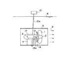
従来の水域浄化装置としては、図9(縦断面図)に示すようなものがあり、水底22に設置された水平ダクト5の内部に、モーター3で駆動されるスクリュープロペラ1が、支持台4で支持されるようにして設けられている。そして、モータ3の電源20が、水面6の上方で、図示しない台船等に設けられ、同電源20からの給電ケーブル20aがモーター3に接続されるように延在している。
このような水域浄化装置では、スクリュープロペラ1からの水流9により所要水域内に水の流れを生起させて、淀みを無くし、自然の浄化作用が促進されるようになっている。
【0003】
また図10に示す従来の水域浄化装置では、水面6の上方で、図示しない台船等に搭載されたエア・コンプレッサー10からホース10aを介し水底の多孔ノズル部材21に送気されるようになっており、同ノズル部材21から発生する気泡群21aにより水中の酸素溶存量の増加がもたらされるようになっている。
【0004】
【発明が解決しようとする課題】
ところで、前述のような従来の水域浄化装置では、図11に示す装置の場合、所要水域における水の流れが促進されるものの、水中の酸素溶存量を積極的に増加させることはできない。
【0005】
また、図12に示す装置では、多孔ノズル部材21から噴出する気泡群21aが水平方向に拡がることなく直ちに上昇してしまうため、広い水域の浄化のためには多数の多孔ノズル部材21の設置を必要とし、大幅なコスト高を招くことになる。
そこで本発明は、所要水域における水流の生起と、微細気泡群の水平方向への拡散とを効率よく行なえるようにした水域浄化装置を提供することを課題とする。
【0006】
【課題を解決するための手段】
前述の課題を解決するため、本発明の水域浄化装置は、水中でほぼ水平方向に水流を発生するように設けられたスクリュープロペラと、同プロペラの回転駆動機構とをそなえ、上記水流に微細気泡を多量に混入すべく配置された多孔質板付き空気噴出部と、同空気噴出部へ送気管を介し圧縮空気を送るエア・コンプレッサーとが設けられて、上記多孔質板付き空気噴出部が、上記スクリュープロペラのプロペラボス部からプロペラ翼に対応して放射状に突設された通気部材に装着されていることを特徴としている。
【0007】
上述の本発明の水域浄化装置では、回転駆動機構により駆動されるスクリュープロペラの作用で所要水域にほぼ水平方向に流れる水流が生起されるが、その際、同スクリュープロペラのプロペラボス部から放射状に突設された通気部材の多孔質板付き空気噴出部から噴出する気泡が、同通気部材の回転に伴い微細気泡に剪断されるので、上記スクリュープロペラから生じる水流に上記微細気泡が混入して遠方まで流れるようになり、広い範囲にわたり酸素溶存量が増加するようになって、水域浄化が効率よく促進されるようになる。
【0008】
また、本発明の水域浄化装置は、水中でほぼ水平方向に水流を発生するように設けられたスクリュープロペラと、同プロペラの回転駆動機構とをそなえるとともに、上記スクリュープロペラを覆うようにほぼ水平に配置されたダクトと、同ダクトの中心軸線から放射状に配設されて上記スクリュープロペラからの水流を整流する整流翼とをそなえ、上記水流に微細気泡を多量に混入すべく配置された多孔質板付き空気噴出部と、同空気噴出部へ送気管を介し圧縮空気を送るエア・コンプレッサーとが設けられて、上記多孔質板付き空気噴出部が、上記整流翼に開口するように配設されたことを特徴としている。
【0009】
上述の本発明の水域浄化装置では、スクリュープロペラからの旋回流が、同スクリュープロペラを覆うダクトに放射状に設けられた整流翼で直線流に変換されて遠方まで届くようになるが、その際、上記整流翼自体に設けられた多孔質板付き空気噴出部から噴出する気泡が、上記直線流に満遍なく混入して、水域浄化作用が広い範囲にわたり効率よく行なわれるようになる。そして、上記整流翼は固定的に設けられるものであるから、同整流翼に付設された多孔質板付き空気噴出部への給気のための配管工事が容易になる利点もある。
【0010】
さらに、本発明の水域浄化装置は、水中でほぼ水平方向に水流を発生するように設けられたスクリュープロペラと、同プロペラの回転駆動機構と、同回転駆動機構を覆うケーシングとをそなえ、上記水流に微細気泡を多量に混入すべく配置された多孔質板付き空気噴出部と、同空気噴出部へ送気管を介し圧縮空気を送るエア・コンプレッサーとが設けられて、上記多孔質板付き空気噴出部が、上記スクリュープロペラの近傍で上記ケーシングから放射状に突設された通気部材に装着されていることを特徴としている。
【0011】
上述の本発明の水域浄化装置のように、スクリュープロペラのプロペラ翼近傍で、同スクリュープロペラの回転駆動機構を覆うケーシングから放射状に突設された通気部材に多孔質板付き空気噴出部が設けられていると、上記スクリュープロペラの回転作動に伴い発生する水流へ上記多孔質板付き空気噴出部からの気泡が効率よく混入しながら破砕されて微細気泡となり、その気泡水流が遠方まで到達するようになって、水域浄化作用が的確に行なわれるようになる。
そして、この場合も上記通気部材が固定状態で設けられるので、エア・コンプレッサーから上記通気部材への配管工事が容易になる。
【0012】
【発明の実施の形態】
以下、図面により本発明の実施形態について説明すると、図1は本発明の第1実施形態としての水域浄化装置を示す縦断面図、図2は図1の装置の要部を拡大して示す縦断面図、図3は図2のA−A矢視断面図、図4は図2のB−B矢視断面図であり、図5は本発明の第2実施形態としての水域浄化装置の要部を示す縦断面図、図6は図5の装置の正面図、図7は図5,6の装置における整流翼の作用を示す説明図、図8は本発明の第3実施形態としての水域浄化装置の要部を示す縦断面図である。
【0013】
まず本発明の第1実施形態について説明すると、図1〜4に示すように、水面6の下方の水中で図示しない支持手段により支持されたダクト5がほぼ水平に設けられており、同ダクト5内には、支持台4で支持されたケーシング17内の回転駆動機構としてのモーター3で回転軸18を介し駆動されるスクリュープロペラ1が、同一中心軸線を有するように設けられている。
【0014】
なおダクト5の支持手段としては、図示しない台船等により支持索を介して懸吊する手段や、ダクト5に浮体を付設して、同ダクト5の浮上を抑制するシンカー付き係留索を設ける手段などが用いられる。
また、モーター3の図示しない電源も、水面6に浮かぶ浮体などに搭載され、同電源から給電ケーブルを介してモーター3への給電が行なわれる。
【0015】
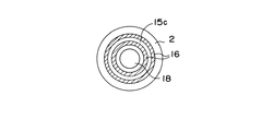
本実施形態では、特にスクリュープロペラ1のプロペラボス2において、プロペラ翼と対応するように放射状に突出した4個の通気部材13が上流側に設けられている。そして、各通気部材13の後縁には、多孔質板付き空気噴出部14が設けられて、同空気噴出部14には、水面6の上方のエア・コンプレッサー10からホース10aおよび空気通路15a〜15dを介して圧縮空気が送られるようになっている。なお、ケーシング17とプロペラボス2との隙間では、リング状の空気通路15cが、図2,3に示すように、2重のリング状シール16の相互間に形成されている。
【0016】
上述の第1実施形態の水域浄化装置では、モーター3により駆動されるスクリュープロペラ1の作用で所要水域にほぼ水平方向に流れる水流9が生起されるが、その際、同スクリュープロペラ1のプロペラボス部2から放射状に突設された通気部材13の多孔質板付き空気噴出部14から噴出する気泡が、同通気部材13の回転に伴い微細気泡に剪断されるので、スクリュープロペラ1から生じる水流9に上記微細気泡が混入して遠方まで流れるようになり、広い範囲にわたり酸素溶存量が増加するようになって、水域浄化が効率よく促進されるようになる。
【0021】
次に本発明の第2実施形態について説明すると、図5,6に示すように、水面6の下方の水中で図示しない支持手段により支持されたダクト5がほぼ水平に設けられており、同ダクト5内には、支持台4で支持された回転駆動機構としてのモーター3で駆動されるスクリュープロペラ1が同一中心軸線を有するように設けられている。そして、ダクト5の支持手段としては、前述の第1実施形態と同様の手段が採用される。また、モーター3の図示しない電源も、前述と同様に設けられる。
【0022】
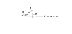
この第2実施形態では、ダクト5の後流側端部に、スクリュープロペラ1からの旋回流を直線流に変換する複数個の整流翼11が、同ダクト5の中心軸線から放射状に配設されている。すなわち、図7に示すように、スクリュープロペラの回転12に伴う旋回水流9が整流翼11に流入することにより、同整流翼11でダクト中心軸線の方向の直線流に変換されるようになっている。
【0023】
さらに、本実施形態では、図5に示すごとく、各整流翼11に多孔質板付き空気噴出部14が設けられていて、各空気噴出部14には水面上方のエア・コンプレッサー10からホース10aを介して圧縮空気が供給されるように構成されている。
【0024】
なお、ダクト5は、整流翼11を設けられるダクト端部へ向かって直径がしだいに減少するテーパー部5aを有しており、これによりスクリュープロペラ1の回転作動に伴ってダクト5から流出する水流が加速されるようになっている。
【0025】
上述の第2実施形態の水域浄化装置では、スクリュープロペラ1からの旋回流が、同スクリュープロペラ1を覆うダクト5に放射状に設けられた整流翼11で直線流に変換されて遠方まで届くようになるが、その際、整流翼11自体に設けられた多孔質板付き空気噴出部14から噴出する気泡が、前記直線流に満遍なく混入して、水域浄化作用が広い範囲にわたり効率よく行なわれるようになる。そして、整流翼11は固定的に設けられるものであるから、同整流翼11に付設された多孔質板付き空気噴出部14への給気のための配管工事が容易になる利点もある。
【0026】
次に本発明の第3実施形態について説明すると、図8に示すように、本実施形態の場合も水面6の下方の水中で図示しない支持手段により支持されたダクト5がほぼ水平に設けられており、同ダクト5内には、支持台4で支持されたケーシング17内の回転駆動機構としてのモーター3で回転軸18を介し駆動されるスクリュープロペラ1が、同一中心軸線を有するように設けられている。なお、ダクト5の支持手段としては、前述の第1実施形態と同様の手段が用いられ、またモーター3の図示しない電源も、前述と同様に設けられる。
【0027】
この第3実施形態では、特にケーシング17の外周部において、スクリュープロペラ1の近傍に、同ケーシング17から放射状に突出した複数の通気部材13aが設けられている。そして、各通気部材13aの後縁には、多孔質板付き空気噴出部14が設けられて、同空気噴出部14には、水面6の上方のエア・コンプレッサー10からホース10aおよび空気通路を介して圧縮空気が送られるようになっている。
【0028】
上述の第3実施形態の水域浄化装置では、スクリュープロペラ1のプロペラ翼近傍で、同スクリュープロペラ1の回転駆動機構としてのモーター3を覆うケーシング17から放射状に突設された通気部材13aに多孔質板付き空気噴出部14が設けられているので、スクリュープロペラ1の回転作動に伴い発生する水流へ多孔質板付き空気噴出部14からの気泡が効率よく混入しながら破砕されて微細気泡となり、その気泡水流9が遠方まで到達するようになって、水域浄化作用が的確に行なわれるようになる。そして、この場合も通気部材13aが固定状態で設けられるので、エア・コンプレッサー10から通気部材13aへの配管工事が容易になる。
【0029】
【発明の効果】
以上詳述したように、本発明の水域浄化装置によれば、次のような効果が得られる。
(1) スクリュープロペラのプロペラボス部から放射状に突設された通気部材の多孔質板付き空気噴出部から噴出する気泡が、同通気部材の回転に伴い微細気泡に剪断されるので、上記スクリュープロペラから生じる水流に上記微細気泡が混入して遠方まで流れるようになり、広い範囲にわたり酸素溶存量が増加するようになって、水域浄化が効率よく促進されるようになる。
(2) スクリュープロペラを覆うダクトに整流翼が放射状に設けられて、同整流翼に多孔質板付き空気噴出部が設けられる場合は、上記スクリュープロペラからの旋回流が上記整流翼で直線流に変換されて遠方まで届くようになるが、その際、上記整流翼自体に設けられた多孔質板付き空気噴出部から噴出する気泡が、上記直線流に満遍なく混入して、水域浄化作用が広い範囲にわたり効率よく行なわれるようになる。そして、上記整流翼は固定的に設けられるものであるから、同整流翼に付設された多孔質板付き空気噴出部への給気のための配管工事が容易になる利点もある。
(3) スクリュープロペラのプロペラ翼近傍で、同スクリュープロペラの回転駆動機構を覆うケーシングから放射状に突設された通気部材に多孔質板付き空気噴出部が設けられていると、上記スクリュープロペラの回転作動に伴い発生する水流へ上記多孔質板付き空気噴出部からの気泡が効率よく混入しながら破砕されて微細気泡となり、その気泡水流が遠方まで到達するようになって、水域浄化作用が的確に行なわれるようになる。そして、この場合も上記通気部材が固定状態で設けられるので、エア・コンプレッサーから上記通気部材への配管工事が容易になる。
【図面の簡単な説明】
【図1】 本発明の第1実施形態としての水域浄化装置を示す縦断面図である。
【図2】 図1の装置の要部を拡大して示す縦断面図である。
【図3】 図2のA−A矢視断面図である。
【図4】 図2のB−B矢視断面図である。
【図5】 本発明の第2実施形態としての水域浄化装置の要部を示す縦断面図である。
【図6】 図5の装置の正面図である。
【図7】 図5,6の装置における整流翼の作用を示す説明図である。
【図8】 本発明の第3実施形態としての水域浄化装置の要部を示す縦断面図である。
【図9】 従来の水域浄化装置の一例を示す縦断面図である。
【図10】 従来の水域浄化装置の他の例を示す立面図である。
【符号の説明】
1 スクリュープロペラ
2 プロペラボス部
3 モーター(回転駆動機構)
4 支持台
5 ダクト
5a ダクトテーパー部
6 水面
9 水流
10 エア・コンプレッサー
10a ホース
11 整流翼
12 回転方向
13,13a 通気部材
14 多孔質板付き空気噴出部
15a〜15d 空気通路
16 リング状シール
17 ケーシング
18 回転軸
20 電源
20a 給電ケーブル
21 多孔ノズル部材
21a 気泡
22 水底[0001]
BACKGROUND OF THE INVENTION
The present invention relates to a water purification apparatus used for improving the environment and culturing seafood.
[0002]
[Prior art]
A conventional water purification apparatus is shown in FIG. 9 (longitudinal sectional view), and a screw propeller 1 driven by a motor 3 is installed in a horizontal duct 5 installed on the bottom 22 of a water. It is provided so that it may be supported. A power source 20 of the motor 3 is provided above the water surface 6 on a not-shown trolley or the like, and extends so that a power supply cable 20 a from the power source 20 is connected to the motor 3.
In such a water purification apparatus, the water flow 9 from the screw propeller 1 causes a flow of water in the required water area to eliminate stagnation and promote a natural purification action.
[0003]
Further, in the conventional water purification apparatus shown in FIG. 10 , air is supplied to the porous nozzle member 21 at the bottom of the water via the hose 10a from an air compressor 10 mounted on a trolley (not shown) above the water surface 6. The bubble group 21a generated from the nozzle member 21 increases the amount of dissolved oxygen in the water.
[0004]
[Problems to be solved by the invention]
By the way, in the conventional water purification apparatus as described above, in the case of the apparatus shown in FIG. 11, the flow of water in the required water area is promoted, but the amount of dissolved oxygen in water cannot be increased positively.
[0005]
In addition, in the apparatus shown in FIG. 12, the bubble group 21a ejected from the porous nozzle member 21 rises immediately without spreading in the horizontal direction. Therefore, in order to purify a wide water area, a large number of porous nozzle members 21 must be installed. Necessary and incurs significant costs.
Then, this invention makes it a subject to provide the water purification apparatus which can perform efficiently generation | occurrence | production of the water flow in a required water area, and the spreading | diffusion of a microbubble group to a horizontal direction.
[0006]
[Means for Solving the Problems]
In order to solve the above-mentioned problem, the water purification apparatus of the present invention comprises a screw propeller provided so as to generate a water flow in water in a substantially horizontal direction and a rotation drive mechanism of the propeller, and the water flow includes fine bubbles. An air jet part with a porous plate arranged to mix a large amount of air, and an air compressor for sending compressed air to the air jet part via an air feed pipe, the air jet part with a porous plate, The screw propeller is mounted on a ventilation member that projects radially from the propeller boss portion corresponding to the propeller blade.
[0007]
In the water area purification apparatus of the present invention described above, a water flow that flows in a substantially horizontal direction is generated in the required water area by the action of the screw propeller driven by the rotation drive mechanism, and at this time, the propeller boss part of the screw propeller radially Bubbles ejected from the air ejection part with the porous plate of the vent member protruding are sheared into fine bubbles as the vent member rotates, so that the fine bubbles are mixed into the water flow generated from the screw propeller and distant. As the amount of dissolved oxygen increases over a wide range, water purification is promoted efficiently .
[0008]
Also, water purification device of the present invention comprises a screw propeller which is provided to generate a flow substantially horizontally in the water, provided with a rotation drive mechanism of the propeller, substantially horizontal so as to cover the screw propeller And a duct arranged radially from the central axis of the duct and rectifying blades for rectifying the water flow from the screw propeller, and arranged to mix a large amount of fine bubbles in the water flow An air jet part with a plate and an air compressor for sending compressed air to the air jet part via an air feed pipe are provided, and the air jet part with the porous plate is arranged to open to the rectifying blade. It is characterized by that.
[0009]
In the water purification device of the present invention described above, the swirling flow from the screw propeller is converted into a linear flow by the rectifying blades provided radially in the duct covering the screw propeller, and reaches far away. Bubbles ejected from the air ejection part with a porous plate provided in the rectifying blade itself are evenly mixed in the linear flow, and the water purification effect is efficiently performed over a wide range. And since the said rectifier blade is fixedly provided, there also exists an advantage that the piping construction for the air supply to the air ejection part with a porous board attached to the same rectifier blade becomes easy.
[0010]
Further, the water purification apparatus of the present invention comprises a screw propeller provided so as to generate a water flow in water in a substantially horizontal direction, a rotation drive mechanism of the propeller, and a casing covering the rotation drive mechanism, and the water flow An air jet part with a porous plate arranged so as to mix a large amount of fine bubbles into the air jet and an air compressor for sending compressed air to the air jet part through an air feed pipe are provided. The portion is mounted on a ventilation member that projects radially from the casing in the vicinity of the screw propeller.
[0011]
As in the water purification apparatus of the present invention described above, an air ejection part with a porous plate is provided on a ventilation member that is radially projected from a casing that covers the rotational drive mechanism of the screw propeller in the vicinity of the propeller blades of the screw propeller. The bubbles from the air ejection part with the porous plate are crushed into fine water bubbles while efficiently mixing into the water flow generated by the rotation operation of the screw propeller, so that the bubble water flow reaches far away. As a result, the water purification action is performed accurately.
Also in this case, since the ventilation member is provided in a fixed state, piping work from the air compressor to the ventilation member is facilitated.
[0012]
DETAILED DESCRIPTION OF THE INVENTION
DETAILED DESCRIPTION OF THE PREFERRED EMBODIMENTS Hereinafter, embodiments of the present invention will be described with reference to the drawings. FIG. 1 is a longitudinal sectional view showing a water purification apparatus as a first embodiment of the present invention, and FIG. 3 is a cross-sectional view taken along the line AA in FIG. 2, FIG. 4 is a cross-sectional view taken along the line BB in FIG. 2, and FIG. 5 is a schematic diagram of the water purification apparatus according to the second embodiment of the present invention . longitudinal sectional view showing a part, FIG. 6 is a front view of the apparatus of FIG. 5, FIG. 7 is an explanatory diagram showing the operation of the rectifier blades in the apparatus of FIG. 5, 6, water as a third embodiment of FIG. 8 is the invention It is a longitudinal cross-sectional view which shows the principal part of a purification apparatus.
[0013]
First, a first embodiment of the present invention will be described. As shown in FIGS. 1 to 4, a duct 5 supported by support means (not shown) in water below the water surface 6 is provided substantially horizontally. Inside, a screw propeller 1 driven by a motor 3 as a rotational drive mechanism in a casing 17 supported by a support 4 via a rotary shaft 18 is provided so as to have the same central axis.
[0014]
As the support means for the duct 5, means for suspending via a support rope by a not-shown trolley or the like, means for attaching a floating body to the duct 5 and providing a mooring line with a sinker for suppressing the rise of the duct 5 Etc. are used.
In addition, a power source (not shown) of the motor 3 is also mounted on a floating body or the like floating on the water surface 6, and power is supplied to the motor 3 from the power source via a power feeding cable.
[0015]
In the present embodiment, in particular, in the propeller boss 2 of the screw propeller 1, four ventilation members 13 projecting radially so as to correspond to the propeller blades are provided on the upstream side. And the air ejection part 14 with a porous board is provided in the rear edge of each ventilation member 13, and the hose 10a and the air passage 15a-from the air compressor 10 above the water surface 6 to the same air ejection part 14 are provided. Compressed air is sent through 15d. In the gap between the casing 17 and the propeller boss 2, a ring-shaped air passage 15c is formed between the double ring-shaped seals 16 as shown in FIGS.
[0016]
In the water area purification apparatus of the first embodiment described above, a water flow 9 flowing in a substantially horizontal direction is generated in the required water area by the action of the screw propeller 1 driven by the motor 3, and at this time, the propeller boss of the screw propeller 1 is generated. Since the air bubbles ejected from the air ejection part 14 with the porous plate of the ventilation member 13 projecting radially from the part 2 are sheared into fine bubbles as the ventilation member 13 rotates, the water flow 9 generated from the screw propeller 1 The above-mentioned fine bubbles are mixed and flow far away, so that the amount of dissolved oxygen increases over a wide range, and water purification is promoted efficiently.
[0021]
Next, a second embodiment of the present invention will be described. As shown in FIGS. 5 and 6 , a duct 5 supported by support means (not shown) in water below the water surface 6 is provided substantially horizontally. In 5, a screw propeller 1 driven by a motor 3 as a rotational drive mechanism supported by a support 4 is provided so as to have the same central axis. And as a support means of the duct 5, the means similar to 1st Embodiment mentioned above is employ | adopted. A power supply (not shown) of the motor 3 is also provided in the same manner as described above.
[0022]
In the second embodiment, the downstream end portion after the duct 5, a plurality pieces of rectifying vanes 11 which converts the swirling flow from the screw propeller 1 to the linear flow is disposed radially from the center axis of the duct 5 ing. That is, as shown in FIG. 7 , when the swirling water flow 9 accompanying the rotation 12 of the screw propeller flows into the rectifying blade 11, the rectifying blade 11 is converted into a linear flow in the direction of the duct center axis. Yes.
[0023]
Furthermore, in the present embodiment, as shown in FIG. 5 , each rectifying blade 11 is provided with an air ejection portion 14 with a porous plate, and each air ejection portion 14 is provided with a hose 10a from the air compressor 10 above the water surface. It is comprised so that compressed air may be supplied through.
[0024]
The duct 5 has a tapered portion 5a whose diameter gradually decreases toward the end of the duct where the rectifying blades 11 are provided, whereby the water flow flowing out of the duct 5 as the screw propeller 1 rotates. Is to be accelerated.
[0025]
In the water purification apparatus of the second embodiment described above, the swirling flow from the screw propeller 1 is converted into a straight flow by the rectifying blades 11 provided radially in the duct 5 covering the screw propeller 1 so as to reach far away. However, at that time, bubbles ejected from the air ejection part 14 with the porous plate provided in the rectifying blade 11 itself are evenly mixed in the linear flow so that the water purification effect is efficiently performed over a wide range. Become. Further, since the rectifying blade 11 is fixedly provided, there is an advantage that piping work for supplying air to the air ejection portion 14 with a porous plate attached to the rectifying blade 11 is facilitated.
[0026]
Next, a third embodiment of the present invention will be described. As shown in FIG. 8 , the duct 5 supported by support means (not shown) in the water below the water surface 6 is provided almost horizontally as shown in FIG. In the duct 5, a screw propeller 1 driven by a motor 3 as a rotational drive mechanism in a casing 17 supported by a support 4 via a rotary shaft 18 is provided so as to have the same central axis. ing. In addition, as a support means of the duct 5, the same means as the above-mentioned 1st Embodiment is used, and the power supply which the motor 3 does not illustrate is provided similarly to the above-mentioned.
[0027]
In the third embodiment, a plurality of ventilation members 13a projecting radially from the casing 17 are provided in the vicinity of the screw propeller 1 particularly in the outer peripheral portion of the casing 17. An air ejection part 14 with a porous plate is provided at the rear edge of each ventilation member 13a. The air ejection part 14 is connected to the air ejection part 14 from the air compressor 10 above the water surface 6 through the hose 10a and the air passage. Compressed air is sent.
[0028]
In the water purification apparatus of the third embodiment described above, a porous member 13a is provided in the vicinity of the propeller blades of the screw propeller 1 so as to project radially from the casing 17 that covers the motor 3 serving as the rotational drive mechanism of the screw propeller 1. Since the plate-equipped air ejecting portion 14 is provided, bubbles from the air ejecting portion 14 with the porous plate are mixed into the water flow generated by the rotation operation of the screw propeller 1 while being efficiently mixed into fine bubbles. The bubbly water flow 9 reaches far away, and the water purification action is performed accurately. Also in this case, since the ventilation member 13a is provided in a fixed state, piping work from the air compressor 10 to the ventilation member 13a is facilitated.
[0029]
【The invention's effect】
As described above in detail, according to the water purification apparatus of the present invention, the following effects can be obtained.
(1) Since the air bubbles ejected from the air ejection part with the porous plate of the ventilation member projecting radially from the propeller boss part of the screw propeller are sheared into fine bubbles as the ventilation member rotates, the screw propeller The fine bubbles are mixed into the water flow generated from the water to flow far, and the amount of dissolved oxygen increases over a wide range, so that water purification is efficiently promoted.
( 2 ) When the rectifying blades are provided radially in the duct that covers the screw propeller, and the air squirting portion with a porous plate is provided on the rectifying wing, the swirling flow from the screw propeller is converted into a straight flow by the rectifying blade. In this case, the bubbles that are ejected from the air ejection part with the porous plate provided in the rectifying blade itself are mixed evenly into the linear flow, and the water purification effect is wide. It will be performed efficiently over a long time. And since the said rectifier blade is fixedly provided, there also exists an advantage that the piping construction for the air supply to the air ejection part with a porous board attached to the same rectifier blade becomes easy.
( 3 ) If the air jetting part with a porous plate is provided in the ventilation member radially projecting from the casing covering the rotation drive mechanism of the screw propeller in the vicinity of the propeller blades of the screw propeller, the rotation of the screw propeller Bubbles from the air jet part with the porous plate are efficiently mixed into the water flow generated by the operation and crushed into fine bubbles, and the bubble water flow reaches far away, so the water purification effect is accurate. To be done. Also in this case, since the ventilation member is provided in a fixed state, piping work from the air compressor to the ventilation member is facilitated.
[Brief description of the drawings]
FIG. 1 is a longitudinal sectional view showing a water purification apparatus as a first embodiment of the present invention.
2 is an enlarged longitudinal sectional view showing a main part of the apparatus shown in FIG.
3 is a cross-sectional view taken along the line AA in FIG. 2;
4 is a cross-sectional view taken along the line B-B in FIG. 2;
FIG. 5 is a longitudinal sectional view showing a main part of a water purification apparatus as a second embodiment of the present invention.
FIG. 6 is a front view of the apparatus of FIG. 5.
7 is an explanatory view showing an operation of rectifying vanes in the apparatus of FIG. 5, 6.
FIG. 8 is a longitudinal sectional view showing a main part of a water purification apparatus as a third embodiment of the present invention.
FIG. 9 is a longitudinal sectional view showing an example of a conventional water purification device.
Figure 1 0 is an elevational view showing another example of a conventional water purifier.
[Explanation of symbols]
1 Screw propeller 2 Propeller boss 3 Motor (rotary drive mechanism)
4 Support stand 5 Duct 5a Duct taper part 6 Water surface 9 Water flow
10 Air compressor
10a hose
11 Rectifier blade
12 Direction of rotation
13, 13a Ventilation member
14 Air ejection part with porous plate
15a-15d air passage
16 Ring seal
17 Casing
18 axis of rotation
20 Power supply
20a Power supply cable
21 Multi-hole nozzle member
21a bubbles
22 Water bottom