JP3696508B2 - Radiator device for vehicle - Google Patents
Radiator device for vehicle Download PDFInfo
- Publication number
- JP3696508B2 JP3696508B2 JP2000403153A JP2000403153A JP3696508B2 JP 3696508 B2 JP3696508 B2 JP 3696508B2 JP 2000403153 A JP2000403153 A JP 2000403153A JP 2000403153 A JP2000403153 A JP 2000403153A JP 3696508 B2 JP3696508 B2 JP 3696508B2
- Authority
- JP
- Japan
- Prior art keywords
- radiator
- engine
- shroud
- vehicle
- tank
- Prior art date
- Legal status (The legal status is an assumption and is not a legal conclusion. Google has not performed a legal analysis and makes no representation as to the accuracy of the status listed.)
- Expired - Fee Related
Links
- XLYOFNOQVPJJNP-UHFFFAOYSA-N water Substances O XLYOFNOQVPJJNP-UHFFFAOYSA-N 0.000 claims description 49
- 238000001816 cooling Methods 0.000 claims description 34
- 229920003002 synthetic resin Polymers 0.000 claims description 8
- 239000000057 synthetic resin Substances 0.000 claims description 8
- 239000013013 elastic material Substances 0.000 claims description 7
- 230000005855 radiation Effects 0.000 claims 1
- 239000000498 cooling water Substances 0.000 description 20
- 230000005540 biological transmission Effects 0.000 description 9
- 238000002955 isolation Methods 0.000 description 6
- 230000001939 inductive effect Effects 0.000 description 5
- 239000013585 weight reducing agent Substances 0.000 description 5
- 229910000838 Al alloy Inorganic materials 0.000 description 2
- 238000005266 casting Methods 0.000 description 2
- 230000017525 heat dissipation Effects 0.000 description 2
- 239000000463 material Substances 0.000 description 2
- 229910052751 metal Inorganic materials 0.000 description 2
- 239000002184 metal Substances 0.000 description 2
- 238000012986 modification Methods 0.000 description 2
- 230000004048 modification Effects 0.000 description 2
- 230000002093 peripheral effect Effects 0.000 description 2
- 238000013022 venting Methods 0.000 description 2
- 238000013459 approach Methods 0.000 description 1
- 230000000903 blocking effect Effects 0.000 description 1
- 238000004891 communication Methods 0.000 description 1
- 230000007423 decrease Effects 0.000 description 1
- 238000013461 design Methods 0.000 description 1
- 238000006073 displacement reaction Methods 0.000 description 1
- 230000000694 effects Effects 0.000 description 1
- 230000005489 elastic deformation Effects 0.000 description 1
- 239000002828 fuel tank Substances 0.000 description 1
- 238000010438 heat treatment Methods 0.000 description 1
- 238000002347 injection Methods 0.000 description 1
- 239000007924 injection Substances 0.000 description 1
- 238000012423 maintenance Methods 0.000 description 1
- 230000001105 regulatory effect Effects 0.000 description 1
- 239000006200 vaporizer Substances 0.000 description 1
- 238000010792 warming Methods 0.000 description 1
Images


Classifications
-
- F—MECHANICAL ENGINEERING; LIGHTING; HEATING; WEAPONS; BLASTING
- F02—COMBUSTION ENGINES; HOT-GAS OR COMBUSTION-PRODUCT ENGINE PLANTS
- F02B—INTERNAL-COMBUSTION PISTON ENGINES; COMBUSTION ENGINES IN GENERAL
- F02B61/00—Adaptations of engines for driving vehicles or for driving propellers; Combinations of engines with gearing
- F02B61/02—Adaptations of engines for driving vehicles or for driving propellers; Combinations of engines with gearing for driving cycles
-
- F—MECHANICAL ENGINEERING; LIGHTING; HEATING; WEAPONS; BLASTING
- F01—MACHINES OR ENGINES IN GENERAL; ENGINE PLANTS IN GENERAL; STEAM ENGINES
- F01P—COOLING OF MACHINES OR ENGINES IN GENERAL; COOLING OF INTERNAL-COMBUSTION ENGINES
- F01P11/00—Component parts, details, or accessories not provided for in, or of interest apart from, groups F01P1/00 - F01P9/00
- F01P11/10—Guiding or ducting cooling-air, to, or from, liquid-to-air heat exchangers
-
- F—MECHANICAL ENGINEERING; LIGHTING; HEATING; WEAPONS; BLASTING
- F01—MACHINES OR ENGINES IN GENERAL; ENGINE PLANTS IN GENERAL; STEAM ENGINES
- F01P—COOLING OF MACHINES OR ENGINES IN GENERAL; COOLING OF INTERNAL-COMBUSTION ENGINES
- F01P3/00—Liquid cooling
- F01P3/18—Arrangements or mounting of liquid-to-air heat-exchangers
-
- F—MECHANICAL ENGINEERING; LIGHTING; HEATING; WEAPONS; BLASTING
- F01—MACHINES OR ENGINES IN GENERAL; ENGINE PLANTS IN GENERAL; STEAM ENGINES
- F01P—COOLING OF MACHINES OR ENGINES IN GENERAL; COOLING OF INTERNAL-COMBUSTION ENGINES
- F01P5/00—Pumping cooling-air or liquid coolants
- F01P5/02—Pumping cooling-air; Arrangements of cooling-air pumps, e.g. fans or blowers
- F01P5/06—Guiding or ducting air to, or from, ducted fans
-
- F—MECHANICAL ENGINEERING; LIGHTING; HEATING; WEAPONS; BLASTING
- F28—HEAT EXCHANGE IN GENERAL
- F28D—HEAT-EXCHANGE APPARATUS, NOT PROVIDED FOR IN ANOTHER SUBCLASS, IN WHICH THE HEAT-EXCHANGE MEDIA DO NOT COME INTO DIRECT CONTACT
- F28D1/00—Heat-exchange apparatus having stationary conduit assemblies for one heat-exchange medium only, the media being in contact with different sides of the conduit wall, in which the other heat-exchange medium is a large body of fluid, e.g. domestic or motor car radiators
- F28D1/02—Heat-exchange apparatus having stationary conduit assemblies for one heat-exchange medium only, the media being in contact with different sides of the conduit wall, in which the other heat-exchange medium is a large body of fluid, e.g. domestic or motor car radiators with heat-exchange conduits immersed in the body of fluid
- F28D1/04—Heat-exchange apparatus having stationary conduit assemblies for one heat-exchange medium only, the media being in contact with different sides of the conduit wall, in which the other heat-exchange medium is a large body of fluid, e.g. domestic or motor car radiators with heat-exchange conduits immersed in the body of fluid with tubular conduits
- F28D1/053—Heat-exchange apparatus having stationary conduit assemblies for one heat-exchange medium only, the media being in contact with different sides of the conduit wall, in which the other heat-exchange medium is a large body of fluid, e.g. domestic or motor car radiators with heat-exchange conduits immersed in the body of fluid with tubular conduits the conduits being straight
- F28D1/0535—Heat-exchange apparatus having stationary conduit assemblies for one heat-exchange medium only, the media being in contact with different sides of the conduit wall, in which the other heat-exchange medium is a large body of fluid, e.g. domestic or motor car radiators with heat-exchange conduits immersed in the body of fluid with tubular conduits the conduits being straight the conduits having a non-circular cross-section
- F28D1/05366—Assemblies of conduits connected to common headers, e.g. core type radiators
-
- B—PERFORMING OPERATIONS; TRANSPORTING
- B62—LAND VEHICLES FOR TRAVELLING OTHERWISE THAN ON RAILS
- B62K—CYCLES; CYCLE FRAMES; CYCLE STEERING DEVICES; RIDER-OPERATED TERMINAL CONTROLS SPECIALLY ADAPTED FOR CYCLES; CYCLE AXLE SUSPENSIONS; CYCLE SIDE-CARS, FORECARS, OR THE LIKE
- B62K2202/00—Motorised scooters
-
- F—MECHANICAL ENGINEERING; LIGHTING; HEATING; WEAPONS; BLASTING
- F01—MACHINES OR ENGINES IN GENERAL; ENGINE PLANTS IN GENERAL; STEAM ENGINES
- F01P—COOLING OF MACHINES OR ENGINES IN GENERAL; COOLING OF INTERNAL-COMBUSTION ENGINES
- F01P2050/00—Applications
- F01P2050/16—Motor-cycles
-
- F—MECHANICAL ENGINEERING; LIGHTING; HEATING; WEAPONS; BLASTING
- F01—MACHINES OR ENGINES IN GENERAL; ENGINE PLANTS IN GENERAL; STEAM ENGINES
- F01P—COOLING OF MACHINES OR ENGINES IN GENERAL; COOLING OF INTERNAL-COMBUSTION ENGINES
- F01P2070/00—Details
- F01P2070/52—Details mounting heat-exchangers
-
- F—MECHANICAL ENGINEERING; LIGHTING; HEATING; WEAPONS; BLASTING
- F28—HEAT EXCHANGE IN GENERAL
- F28F—DETAILS OF HEAT-EXCHANGE AND HEAT-TRANSFER APPARATUS, OF GENERAL APPLICATION
- F28F2255/00—Heat exchanger elements made of materials having special features or resulting from particular manufacturing processes
- F28F2255/02—Flexible elements
-
- Y—GENERAL TAGGING OF NEW TECHNOLOGICAL DEVELOPMENTS; GENERAL TAGGING OF CROSS-SECTIONAL TECHNOLOGIES SPANNING OVER SEVERAL SECTIONS OF THE IPC; TECHNICAL SUBJECTS COVERED BY FORMER USPC CROSS-REFERENCE ART COLLECTIONS [XRACs] AND DIGESTS
- Y10—TECHNICAL SUBJECTS COVERED BY FORMER USPC
- Y10S—TECHNICAL SUBJECTS COVERED BY FORMER USPC CROSS-REFERENCE ART COLLECTIONS [XRACs] AND DIGESTS
- Y10S165/00—Heat exchange
- Y10S165/905—Materials of manufacture
Landscapes
- Engineering & Computer Science (AREA)
- Mechanical Engineering (AREA)
- General Engineering & Computer Science (AREA)
- Chemical & Material Sciences (AREA)
- Combustion & Propulsion (AREA)
- Physics & Mathematics (AREA)
- Thermal Sciences (AREA)
- Cooling, Air Intake And Gas Exhaust, And Fuel Tank Arrangements In Propulsion Units (AREA)
Description
【0001】
【発明の属する技術分野】
本発明は、車体フレームに支持されるパワーユニットのエンジンに、第1及び第2タンク間を放熱コアを介して連結してなるラジエータを取り付け、前記第1タンクをエンジンのウォータジャケットの入口に、前記第2タンクを前記ウォータジャケットの出口にそれぞれ連通した、車両用ラジエータ装置の改良に関する。
【0002】
【従来の技術】
かゝる車両用ラジエータ装置は、例えば特許第2649179号公報に開示されているように、既に知られている。
【0003】
【発明が解決しようとする課題】
かゝる車両用ラジエータ装置は、エンジン及びラジエータ間の配管の簡素化を図る点で有利となるが、ラジエータがエンジンにより加振されることを防ぐため、ラジエータを特別な弾性支持手段を介してエンジンに取り付けており、しかもラジエータの重量が比較的大きいことから、上記弾性支持手段も比較的負荷容量の大きいものとなり、コスト低減の妨げとなっている。
【0004】
本発明は、かゝる事情に鑑みてなされたもので、ラジエータの軽量化を図ると共に、簡単で安価な構造によりラジエータをエンジンに防振的に支持し得るようにした車両用ラジエータ装置を提供することを目的とする。
【0005】
【課題を解決するための手段】
上記目的を達成するために、本発明は、車体フレームに支持されるパワーユニットのエンジンに、第1及び第2タンク間を放熱コアを介して連結してなるラジエータを取り付け、前記第1タンクをエンジンのウォータジャケットの入口に、前記第2タンクを前記ウォータジャケットの出口にそれぞれ連通した、車両用ラジエータ装置において、前記ラジエータを、エンジンの冷却ファン外周を囲繞し且つ該ラジエータの冷却風を誘導する弾性材製のシュラウドを介してエンジンに取り付け、そのシュラウドには、ラジエータを通過した冷却風を前記冷却ファンの径方向外方に排出し得る複数の排出口が設けられることを第1の特徴とする。
【0006】
この第1の特徴によれば、ラジエータの冷却風を誘導するシュラウドを弾性材製とすると共に、それを介してラジエータをエンジン本体に取り付けたので、シュラウドは、ラジエータの冷却風を誘導する本来の機能の外に、エンジンからラジエータへの振動の伝達を遮断する防振機能を発揮することができ、したがってラジエータの専用の防振手段が不要となり、構造の簡素化、延いてはコストの低減を大いに図ることができる。
【0007】
また本発明は、車体フレームにパワーユニットをピボット軸を介して上下揺動可能に連結すると共にリヤクッションを介して支持し、そのパワーユニットのエンジンに、第1及び第2タンク間を放熱コアを介して連結してなるラジエータを取り付けると共に、そのラジエータを該エンジンのクランクケース側方に配置し、エンジンのシリンダブロックに設けたウォータジャケットの入口に前記第1タンクの接続部を、また同ウォータジャケットの出口に前記第2タンクの接続部をそれぞれ連通した、車両用ラジエータ装置において、前記ラジエータを、このラジエータの冷却風を誘導する弾性材製のシュラウドを介してエンジンに取り付け、前記ラジエータは、前記第1及び第2タンクの相互間距離よりも各タンクが長い横長形状に形成され、その第1及び第2タンクの、シリンダヘッド寄りの各端部に前記接続部がそれぞれ設けられることを第2の特徴とする。
【0008】
この第2の特徴によれば、ラジエータの冷却風を誘導するシュラウドを弾性材製とすると共に、それを介してラジエータをエンジン本体に取り付けたので、シュラウドは、ラジエータの冷却風を誘導する本来の機能の外に、エンジンからラジエータへの振動の伝達を遮断する防振機能を発揮することができ、したがってラジエータの専用の防振手段が不要となり、構造の簡素化、延いてはコストの低減を大いに図ることができる。
【0009】
その上、上記ラジエータは、車体フレームにピボット軸を介して連結されると共にリヤクッションを介して支持されるパワーユニットのエンジンに取り付けられるものであるから、ラジエータ及びシュラウドの上記のような軽量化は、ばね下荷重の軽減をもたらし、車両の乗り心地の改善に寄与し得る。
【0010】
さらに本発明は、第1又は第2の特徴に加えて、前記ラジエータの第1及び第2タンクを合成樹脂製としたことを第3の特徴とする。
【0011】
この第3の特徴によれば、ラジエータの第1及び第2タンクを軽量な合成樹脂製としたことで、ラジエータの軽量化を大いに図ることができる。また、このようなラジエータの軽量化は、シュラウドの負荷容量を小さくして、その薄肉化、延いては更なる防振機能の向上と軽量化をもたらすことができる。
【0012】
さらに本発明は、第1〜第3の何れかの特徴に加えて、前記シュラウドをエンジンに締め付け部材により固着し、前記ラジエータ及び前記ウォータジャケット間を連通する導管の両端部を、前記ラジエータ及びエンジンに設けられた接続孔に前記締め付け部材の締め付け方向で嵌合したことを第4の特徴とする。
【0013】
この第4の特徴によれば、締めつけ部材をもってシュラウドをエンジン本体に固着することにより、導管の接続孔との嵌合状態を保持することができ、したがって導管に特別な抜け止め手段を施す必要がなくなり、配管構造の簡素化を図ることができる。
【0014】
さらにまた本発明は、第1〜第3の何れかの特徴に加えて、前記ラジエータ及び前記シュラウド間をリベットにより結合したことを第5の特徴とする。
【0015】
この第5の特徴によれば、ラジエータ及びシュラウドの組立体を構成して、エンジンへの組み付け性の向上を図ることができる。
【0016】
さらにまた本発明は、第1〜第5の何れかの特徴に加えて、前記エンジンのシリンダブロックが前記クランクケースよりも車体前側に配置されていると共に、そのシリンダボアの軸線が車体前上がりに傾斜していることを特徴とする。
【0017】
尚、前記第1及び第2タンク、導管並びに締めつけ部材は、後述する本発明の実施例中の下部及び上部タンク77、78、第2導管92並びにボルト108にそれぞれに対応する。
【0018】
【発明の実施の形態】
以下、本発明の実施の形態を、添付図面に示した本発明の一実施例に基づいて説明する。
【0019】
図1〜図9は本発明の一実施例を示すもので、図1はスクータ型の自動二輪車の全体側面図、図2は図1の2−2線断面図、図3は図2の3−3矢視図、図4はラジエータカバーを取外した状態での図3に対応した側面図、図5は図3の5−5線断面図、図6は図3の6−6線断面図、図7は図3の7矢視図、図8はラジエータにラジエータカバーを取り付けた状態を示す斜視図、図9はクランクシャフトのクランク角度位置を検知する手段の変形例を示す側面図である。
【0020】
先ず、図1において、操向ハンドル11により操舵される前輪Wfと、スイング式のパワーユニットPにより駆動される後輪Wrとを備えたスクータ型の自動二輪車Vの車体フレームFは、フロントフレーム12、センターフレーム13及びリヤフレーム14に3分割される。フロントフレーム12は、ヘッドパイプ12a、ダウンチューブ12b及びステップフロア12cを一体に備えたアルミ合金の鋳造品から構成される。パワーユニットPがピボット軸15を介して上下揺動自在に支持されるセンターフレーム13もアルミ合金の鋳造品から構成され、フロントフレーム12の後端に結合される。パワーユニットPの後上方に延びるリヤフレーム14は環状のパイプ材から構成され、このリヤフレーム14に、それに囲繞されるようにして燃料タンク16が支持される。センターフレーム13の上面にはヘルメットケース17が支持されており、シート18を一体に有するリッド19によってヘルメットケース17が開閉自在に覆われる。
【0021】
パワーユニットPは、水冷式の単気筒4サイクルエンジンEと、エンジンEの左側面から車体後方に延びるベルト式の無段変速機Tとからなり、無段変速機Tの後部上面がリヤクッション20を介してセンターフレーム13の後端に結合される。無段変速機Tの上面にはエアクリーナ21が支持され、無段変速機Tの右側面にはマフラー22が支持され、エンジンEの下面には起立・倒伏可能なメインスタンド23が支持される。
【0022】
図2〜図4において、エンジンEのエンジン本体25は、クランクシャフト31の軸線に沿って上下方向に延びる分割面により分割された第1エンジンブロック32及び第2エンジンブロック33を備えており、第1エンジンブロック32は、シリンダボア41を有するシリンダブロック32aと、第2エンジンブロック33と共にクランクケースを構成するクランクケース半部32bとを一体に備え、第1エンジンブロック32の前端にはシリンダヘッド34が結合され、シリンダヘッド34の前端にはヘッドカバー35が結合される。
【0023】
このようなエンジン本体25は、シリンダボア41の軸線Lをわずかに前上がりとして車体フレームFの前後方向に略沿うように、車体フレームFに搭載されるものであり、第1エンジンブロック32の上部に設けられたブラケット27が、車体フレームFのセンターフレーム13に固定されるピボット軸15にマウントゴム28を介して揺動可能に連結される。
【0024】
ベルト式の無段変速機Tは、相互に結合される右側ケーシング37及び左側ケーシング38を備えており、右側ケーシング37の前部右側面が、第1及び第2エンジンブロック32,33の左側面に結合される。さらに右側ケーシング37の後部右側面には減速ケーシング39が結合される。
【0025】
第1エンジンブロック32が備えるシリンダボア41の内部に摺動自在に嵌合するピストン42は、コンロッド43を介してクランクシャフト31に連接される。シリンダヘッド34にはカムシャフト44が回転自在に支持されており、シリンダヘッド34に設けられた吸気バルブ及び排気バルブ(図示せず)がカムシャフト44によって開閉駆動される。第1エンジンブロック32に設けられたチェーン通路40内にはタイミングチェーン45が収納され、該タイミングチェーン45が、クランクシャフト31に設けられた駆動スプロケット46とカムシャフト44に設けられた従動スプロケット47とに巻き掛けられる。これによりカムシャフト44は、クランクシャフト31の2回転につき1回転する。 右側ケーシング37及び左側ケーシング38の内部に突出するクランクシャフト31の左端には駆動プーリ54が設けられる。該駆動プーリ54は、クランクシャフト31に固定された固定側プーリ半体55と、固定側プーリ半体55に対して接近・離間可能な可動側プーリ半体56とを備えており、可動側プーリ半体56はクランクシャフト31の回転数の増加に応じて半径方向外側に移動する遠心ウエイト57によって、固定側プーリ半体55に接近する方向に付勢される。
【0026】
右側ケーシング37の後部及び減速ケーシング39間に支持された出力軸58に設けられた従動プーリ59は、出力軸58に相対回転可能に支持された固定側プーリ半体60と、固定側プーリ半体60に対して接近・離間可能な可動側プーリ半体61とを備えており、可動側プーリ半体61はスプリング62で固定側プーリ半体60に向けて付勢される。また固定側プーリ半体60と出力軸58との間に発進用クラッチ63が設けられる。そして駆動プーリ54及び従動プーリ59間に無端状のVベルト64が巻き掛けられる。
【0027】
右側ケーシング37及び減速ケーシング39間には出力軸58と平行な中間軸65及び車軸66が支持されており、出力軸58、中間軸65及び車軸66間に減速ギヤ列67が設けられる。そして減速ケーシング39を貫通して右側に突出する車軸66の右端に後輪Wrがスプライン嵌合して取り付けられる。
【0028】
而して、クランクシャフト31の回転動力は駆動プーリ54に伝達され、該駆動プーリ54からVベルト64、従動プーリ59、発進用クラッチ63及び減速ギヤ列67を介して後輪Wrに伝達される。
【0029】
エンジンEの低速回転時には、駆動プーリ54の遠心ウエイト57に作用する遠心力が小さいため、従動プーリ59のスプリング62によって固定側プーリ半体60及び可動側プーリ半体61間の溝幅が減少し、変速比はLOWになっている。この状態からクランクシャフト31の回転数が増加すると、遠心ウエイト57に作用する遠心力が増加して駆動プーリ54の固定側プーリ半体55及び可動側プーリ半体56間の溝幅が減少し、それに伴って従動プーリ59の固定側プーリ半体60及び可動側プーリ半体61間の溝幅が増加するため、変速比はLOWからTOPに向かって無段階で変化する。
【0030】
図5を併せて参照して、クランクシャフト31の右側には、ロータ69が固定され、このロータ69と協同して交流発電機68を構成するステータ70が、ロータ69で囲繞されるようにして取り付けベース73に複数本のボルト74…で固着され、その取り付けベース73は複数本のボルト80…で第1及び第2エンジンブロック32,33に固着される。交流発電機68よりも外方でクランクシャフト31の右端部には冷却ファン71が固着されており、冷却ファン71を交流発電機68との間に挟むようにしてラジエータ72が配置される。このラジエータ72は、冷却ファン71を囲繞するシュラウド81を介してエンジン本体25に取り付けられる。
【0031】
ラジエータ72は、上下の間隔を置いて配置される上部及び下部タンク77、78と、これらタンク77、78間を、それらの内部を相互に連通しながら一体的に結合する放熱コア79とから構成される。放熱コア79は放熱性に富む金属製で、その上下両端部には、それぞれ一対の連結突片101,101;102,102を左右に突出させており、上部の連結突片101,101には、下面を開放した上部タンク77の左右両端がシール部材103,103を挟んでかしめ結合され、また下部の連結突片102,102には、上面を開放した下部タンク78の左右両端がシール部材104,104を挟んでかしめ結合される。上部及び下部タンク77、78は何れも合成樹脂を素材として成形されている。 上部及び下部タンク77、78には連結鍔105,106が一体に形成されており、これらに合成樹脂等の弾性材からなる前記シュラウド81の一端部が複数本のリベット107…により固着される。このシュラウド81の他端には連結フランジ81aが一体に形成されており、この連結フランジ81aが複数本のボルト108…によりエンジン本体25に固着される。
【0032】
ラジエータ72は、シュラウド81に複数のビス109…で固着される合成樹脂製のラジエータカバー75で外周を覆われ、このラジエータカバー75と一体成形されたグリル75aが放熱コア79の前面に対向して配置され、このグリル75aを通して外部から放熱コア79に冷却風を導入するようになっている。
【0033】
図6及び図8を併せて参照して、冷却ファン71の側方でシュラウド81には複数の排出口76…が設けられており、冷却ファン71の作動時には、グリル75aから導入された空気はラジエータ72の放熱コア79を通過することで該放熱コア79を冷却し、排出口76…から外部に排出されることになる。こうしてラジエータ72内の冷却水は冷却される。
【0034】
ラジエータ72は、エンジン本体25における第1エンジンブロック32のシリンダブロック32a及びシリンダヘッド34に設けられたウォータージャケット82の冷却水を循環し得る冷却装置83の一部を構成するものであり、該冷却装置83は、ウォータージャケット82に冷却水を供給するウォータポンプ84と、ウォータージャケット82及びウォータポンプ84の吸入口間に介装されるラジエータ72と、このラジエータ72を迂回してウォータージャケット82からの冷却水をウォータポンプ84に戻す状態並びにウォータージャケット82からラジエータ72を経由した冷却水をウォータポンプ84に戻す状態を冷却水の温度に応じて切換えるサーモスタット85とを備える。
【0035】
シリンダヘッド34の右側面には、内部にサーモスタット85を収納したサーモスタットケース86が結合されており、カムシャフト44の右端に設けられたウォータポンプ84がシリンダヘッド34及びサーモスタットケース86によって囲まれた空間に収納される。
【0036】
車体フレームFの前後方向に沿う上部タンク77の一端部(この実施例では後端部)には、上方に延びる給水口管87が一体に設けられており、この給水口管87の上端には、回転操作により開閉される給水キャップ88が装着される。また車体フレームFの前後方向に沿う下部タンク78の他端部(この実施例では前端部)には、前方側に突出した接続管89が一体に設けられる。
【0037】
このようなラジエータ72は、エンジン本体25が備えるシリンダボア41の軸線Lに対して角度αだけ傾斜した姿勢で、前述のようにエンジン本体25に取り付けられ、これによりエンジン本体25の車体フレームFへの搭載時にはラジエータ72が水平面に対して角度βだけ前傾した姿勢となり、給水キャップ88が冷却装置83内の最上方位置に配置されると共に接続管89が冷却装置83内の最下方位置に配置される。こうすることにより、ラジエータ72を特別な形状としたり、ラジエータ72に接続されて該ラジエータ72とは別に配置されるタンクに給水キャップを設けたりすることによるコストの増大を回避して、給水口管87からの注水時に冷却装置83内でのヘッド差を比較的大きくし、給水口管87からのエアー抜き性及び注水性を向上することができる。
【0038】
また上記のようにラジエータ72をシリンダボア41の軸線Lに対して角度αだけ傾斜した姿勢とすると、エンジン本体25を車体フレームFに支持するためのピボット軸25を避けるようにラジエータ72を配置することが可能となると共に、シリンダヘッド32の排気ポートに連なる排気管90をラジエータ72の後部後方に配置するスペースを確保し得て、排気管90の取り回し自由度を向上させることができる。
【0039】
ラジエータ72の接続管89には、ラジエータ72の冷却水をサーモスタット85側に導くゴムホース等からなる可撓性の第1導管91の一端が接続され、第1導管91の他端はサーモスタットケース86に接続される。
【0040】
ラジエータ72は、エンジン本体25のシリンダブロック32aに側面視で上部タンク77の少なくとも一部(この実施例では前部)を重ねる位置に配置されるものであり、上部タンク77及びシリンダブロック32aが前記側面視で重なる範囲において、上部タンク77及びシリンダブロック32aに、上部タンク77内に連なる接続孔115及びウォータジャケット82の上部の出口82oに連なる接続孔116が設けられ、これら接続孔115,116に金属パイプ等からなる剛性を有する第2導管92の両端部が前記ボルト108…の締めつけ方向に沿ってOリング等のシール部材117,118をそれぞれ介して嵌合される。その際、第2導管92は、シュラウド81に設けられた透孔119を無接触で貫通するように配置される。また第2導管92と接続孔115,116との嵌合部には、シール部材117,118を弾性変形させつゝ第2導管92の微小角度の揺動を許容する間隙が設けられる。
【0041】
またウォータポンプ84からの冷却水を導くゴムホース等からなる可撓性の第3導管93の一端がサーモスタットケース86に接続され、この第3導管93の他端は、シリンダブロック32aの下面に突設される、ウォータージャケット82の下部の入口82iに接続される。
【0042】
シリンダヘッド32の吸気ポートに接続される気化器95には、該気化器95を加温するためにウォータージャケット82からの冷却水を導く管路(図示せず)が接続されており、気化器95を加温後の冷却水をサーモスタット85に導くゴムホース等からなる可撓性の第4導管96がサーモスタットケース86に接続される。
【0043】
サーモスタットケース86の上部には、ウォータポンプ84からエアーを抜くためのゴムホース等からなる可撓性の第5導管97が接続されており、この第5導管97と、ウォータージャケット82内の上部からエアーを抜くためにシリンダブロック32aの上部に接続された導管(図示せず)とが、ゴムホース等からなる可撓性の第6導管98に共通に接続されており、この第6導管98がラジエータ72における上部タンク77の後方側上部に接続される。
【0044】
さらに給水口管87には、ゴムホース等からなる可撓性の第7導管100の一端が接続されており、第7導管100の他端は、大気に開放されてラジエータ72とは別に配置されるリザーバ(図示せず)に接続される。而してラジエータ72内の冷却水が高温となって膨張したときには余分な冷却水が前記リザーバに溢流し、ラジエータ72内の冷却水が低温となったときには前記リザーバからラジエータ72に冷却水が戻される。このようなラジエータ72及びリザーバ間での冷却水の流通により、給水口管87内に溜まっていたエアーがリザーバに排出される。すなわちエンジンEの運転時にも冷却装置83からのエアー抜きが良好に行なわれることになる。
【0045】
再び図3、図6及び図7において、ラジエータカバー75は、給水口管87の給水キャップ88の一部を覆う規制部120を一体に備えていて、該カバー75を取り外さない限り給水キャップ88の給水口管87からの離脱ができないようになっている。
【0046】
また図4において、シュラウド81は、ラジエータ72の一側方に張り出す張り出し部81bを一体に備えており、それに覗き窓122と、この覗き窓122の中心側に突出する指針123が形成される。この指針123は、整備作業者が覗き窓122から見ながら、この指針123に前記発電機68のロータ69外周面の所定箇所に刻印された合いマーク(図示せず)を合致させることにより、クランクシャフト31のクランク角度位置を検知するもので、点火時期の調時時等に使用される。上記指針123に代えて、図9に示すように、ステータ70の取り付けベース73の外側面に指針マーク123′を表示し、これとロータ69外周面の合いマークとの合致を覗き窓122から見るようにすることもできる。
【0047】
次に、この実施例の作用について説明する。
【0048】
エンジンEの暖機運転が完了した状態では、カムシャフト44により駆動されるウォータポンプ84から吐出された冷却水は、サーモスタットケース86及び第3導管93を経て第1エンジンブロック32及びシリンダヘッド34内のウオータジャケット82に供給され、ウオータジャケット82を通過する間にエンジンEを冷却し、その後、第2導管92を経てラジエータ72の上部タンク77に送られる。そして上部タンク77から冷却コア79を経て下部タンク78に流下する間に温度低下した冷却水は、第1導管91及びサーモスタット85を経てウォータポンプ84に吸入れる。一方、エンジンEが暖機運転中であって冷却水温度が低いときには、ラジエータ72を迂回して冷却水が循環するようにサーモスタット85が作動し、冷却水はラジエータ72を通過することなくウォータージャケット82、気化器95及びウォータポンプ84を循環して速やかに昇温する。
【0049】
ところで、ラジエータ72の上部及び下部タンク77、78は軽量な合成樹脂製となっているので、ラジエータ72の軽量化を大いに図ることができる。またラジエータ72を通過した冷却風を排出口76…外へ誘導するシュラウド81が弾性材製とされると共に、それを介してラジエータ72がエンジン本体25に取り付けられるので、シュラウド81がそれ自体の弾性によりエンジンEの振動を吸収して、エンジンEからラジエータ72への加振を防ぐことができる。
【0050】
即ち、シュラウド81は、ラジエータ72の冷却風を誘導する本来の機能の外に、エンジンEからラジエータ72への振動の伝達を遮断する防振の役割を持つことになる。したがってラジエータ72の専用の防振手段が不要となり、構造の簡素化、延いてはコストの低減を大いに図ることができる。
【0051】
しかもラジエータ72が上記のように軽量となったことから、シュラウド81の負荷容量を小さくして、その薄肉化、延いては更なる防振機能の向上と軽量化をもたらすことができる。
【0052】
特に、上記ラジエータ72は、車体フレームFにピボット軸15を介して連結されと共にリヤクッション20を介して支持されて後輪Wrを伴い上下揺動するパワーユニットPのエンジンEに取り付けられるものであるから、ラジエータ72及びシュラウド81の上記のような軽量化は、ばね下荷重の軽減をもたらし、車両の乗り心地の改善に寄与する。 また剛性を有する第2導管92は、その両端部を上部タンク77及びエンジン本体25の接続孔115,116に、エンジン本体25及びシュラウド81間を固着するボルト108…の締めつけ方向に沿ってそれぞれシール部材117,118を介して嵌合されるので、シュラウド81をエンジン本体25に重ねる際、第2導管92の両端部をシール部材117,118を介して接続孔115,116に嵌合してから、ボルト108…をもってシュラウド81をエンジン本体25に固着することにより、第2導管92の接続孔115,116との嵌合状態が保持されることになり、第2導管92に特別な抜け止め手段を施す必要がなくなり、配管構造の簡素化を図ることができる。
【0053】
しかも第2導管92は、上記シール部材117,118の弾性変形を伴いエンジン本体25及びラジエータ72に対して僅かに揺動可能であるから、エンジン本体25の振動に伴うエンジン本体25及びラジエータ72間の相対変位が許容される。
【0054】
さらにシュラウド81は、ラジエータ72の上部及び下部タンク77、78にリベット107…で結合されるので、ラジエータ72及びシュラウド81の組立体を構成して、エンジンEへの組み付け性の向上を図ることができる。
【0055】
以上、本発明の実施例を説明したが、本発明は上記実施例に限定されるものではなく、本発明の要旨を逸脱しない範囲で種々の設計変更を行うことができる。例えば、ラジエータ72は、一対のタンク77、78が水平方向に並ぶように配置することもできる。また本発明は、上記自動二輪車V以外の自動三輪車等の各種車両にも適用可能である。
【0056】
【発明の効果】
以上のように本発明の第1及び第2の各特徴によれば、ラジエータを、ラジエータの冷却風を誘導する弾性材製のシュラウドを介してエンジンに取り付けたので、シュラウドがラジエータの冷却風を誘導する本来の機能の外に、エンジンからラジエータへの振動の伝達を遮断する防振機能を発揮することで、ラジエータの専用の防振手段が不要となり、構造の簡素化、延いてはコストの低減を大いに図ることができる。
【0057】
また特に本発明の第1の特徴によれば、エンジンの冷却ファン外周を囲繞するシュラウドに、ラジエータを通過した冷却風を冷却ファンの径方向外方に排出し得る複数の排出口が設けられるので、これら排出口から、ラジエータを通過した冷却風を排出することができる。
【0058】
また本発明の第2の特徴によれば、ラジエータは、車体フレームにピボット軸を介して揺動自在に連結されると共にリヤクッションを介して支持されるパワーユニットのエンジンに取り付けられるものであるから、ラジエータ及びシュラウドの上記のような軽量化は、ばね下荷重の軽減をもたらし、車両の乗り心地の改善に寄与し得る。また上記ラジエータは、第1及び第2タンクの相互間距離よりも各タンクが長い横長形状に形成され、その第1及び第2タンクの、シリンダヘッド寄りの各端部にシリンダブロックのウォータジャケット入口及び出口との接続部がそれぞれ設けられる。
【0059】
さらに本発明の第3の特徴によれば、ラジエータの第1及び第2タンクを軽量な合成樹脂製としたことで、ラジエータの軽量化を大いに図ることができる。また、このようなラジエータの軽量化は、シュラウドの負荷容量を小さくして、その薄肉化、延いては更なる防振機能の向上と軽量化をもたらすことができる。
【0060】
さらにまた本発明の第4の特徴によれば、前記シュラウドをエンジンに締め付け部材により固着し、前記ラジエータ及び前記ウォータジャケット間を連通する導管の両端部を、前記ラジエータ及びエンジンに設けられた接続孔に前記締め付け部材の締め付け方向で嵌合したので、締めつけ部材によるシュラウド及びエンジン本体間の固着と同時に導管の接続孔との嵌合状態を保持することができ、したがって導管に特別な抜け止め手段を施す必要がなくなり、配管構造の簡素化を図ることができる。
【0061】
さらにまた本発明の第5の特徴によれば、第1又は第2の特徴に加えて、前記ラジエータ及び前記シュラウド間をリベットにより結合したので、ラジエータ及びシュラウドの組立体を構成して、エンジンへの組み付け性の向上を図ることができる。
【図面の簡単な説明】
【図1】 本発明の車両用ラジエータ装置を備えるスクータ型の自動二輪車の全体側面図。
【図2】 図1の2−2線断面図。
【図3】 図2の3−3矢視図。
【図4】 ラジエータカバーを取外した状態での図3に対応した側面図。
【図5】 図3の5−5線断面図。
上記自動二輪車におけるエンジン要部の縦断平面図。
【図6】 図3の6−6線断面図。
【図7】 図3の7矢視図。
【図8】 ラジエータにラジエータカバーを取り付けた状態を示す斜視図。
【図9】 クランクシャフトのクランク角度位置を検知する手段の変形例を示す側面図。
【符号の説明】
E・・・・・・エンジン
F・・・・・・車体フレーム
P・・・・・・パワーユニット
15・・・・・ピボット軸
20・・・・・リヤクッション
72・・・・・ラジエータ
77・・・・・第2タンク(上部タンク)
78・・・・・第1タンク(下部タンク)
79・・・・・放熱コア
81・・・・・シュラウド
82・・・・・ウォータジャケット
82i・・・・ウォータジャケットの入口
82o・・・・ウォータジャケットの出口
92・・・・・導管(第2導管)
107・・・・リベット
108・・・・締め付け部材(ボルト)
115・・・・接続孔
116・・・・接続孔[0001]
BACKGROUND OF THE INVENTION
The present invention attaches a radiator formed by connecting the first and second tanks via a heat dissipating core to the engine of the power unit supported by the vehicle body frame, and the first tank is attached to the inlet of the water jacket of the engine. The present invention relates to an improvement in a vehicle radiator device in which a second tank communicates with an outlet of the water jacket.
[0002]
[Prior art]
Such a radiator device for a vehicle is already known as disclosed in, for example, Japanese Patent No. 2649179.
[0003]
[Problems to be solved by the invention]
Such a vehicle radiator device is advantageous in that it simplifies piping between the engine and the radiator. However, in order to prevent the radiator from being vibrated by the engine, the radiator is connected via a special elastic support means. Since it is attached to the engine and the weight of the radiator is relatively large, the elastic support means also has a relatively large load capacity, which hinders cost reduction.
[0004]
The present invention has been made in view of such circumstances, and provides a radiator device for a vehicle that can reduce the weight of the radiator and can support the radiator in an anti-vibration manner with a simple and inexpensive structure. The purpose is to do.
[0005]
[Means for Solving the Problems]
In order to achieve the above object, according to the present invention, a radiator formed by connecting a first and a second tanks via a heat dissipating core is attached to an engine of a power unit supported by a vehicle body frame, and the first tank is connected to the engine. In the vehicle radiator device in which the second tank communicates with the water jacket outlet and the water jacket outlet, respectively, the radiator,Surround the outer periphery of the cooling fan of the engine andAttached to the engine via an elastic shroud that induces cooling air from the radiatorThe shroud is provided with a plurality of outlets through which cooling air that has passed through the radiator can be discharged radially outward of the cooling fan.This is the first feature.
[0006]
According to the first feature, the shroud for inducing the cooling air of the radiator is made of an elastic material, and the radiator is attached to the engine body via the shroud, so that the shroud is inherent to inducing the cooling air of the radiator. In addition to the function, it can exhibit a vibration isolation function that blocks the transmission of vibrations from the engine to the radiator, thus eliminating the need for a dedicated vibration isolation means for the radiator, simplifying the structure and thus reducing costs. It can be greatly planned.
[0007]
The present invention also provides a vehicle body frame.Power unitConnected to swing up and down via pivot shaftYouAnd support through the rear cushionAnd the power unitA radiator that connects the first and second tanks via a heat dissipating core is attached to the engine.And arrange the radiator on the side of the crankcase of the engine,EngineProvided on the cylinder blockAt the entrance of the water jacketThe connecting portion of the first tankAt the exit of the water jacketConnect the connecting part of the second tankIn the vehicle radiator device that is in communication with each other, the radiator is attached to the engine via a shroud made of an elastic material that guides cooling air of the radiator.The radiator is formed in a horizontally long shape in which each tank is longer than the distance between the first and second tanks, and the connection portions are respectively provided at the end portions of the first and second tanks near the cylinder head. Be providedThis is the second feature.
[0008]
According to the second feature, the shroud for inducing the cooling air of the radiator is made of an elastic material, and the radiator is attached to the engine body through the shroud, so that the shroud is inherent to inducing the cooling air of the radiator. In addition to the function, it can exhibit a vibration isolation function that blocks the transmission of vibrations from the engine to the radiator, thus eliminating the need for a dedicated vibration isolation means for the radiator, simplifying the structure and thus reducing costs. It can be greatly planned.
[0009]
In addition, since the radiator is attached to the engine of the power unit that is connected to the vehicle body frame via the pivot shaft and supported via the rear cushion, the weight reduction of the radiator and the shroud as described above is This can reduce the unsprung load and contribute to improving the riding comfort of the vehicle.
[0010]
In addition to the first or second feature, the third feature of the present invention is that the first and second tanks of the radiator are made of synthetic resin.
[0011]
According to the third feature, since the first and second tanks of the radiator are made of a lightweight synthetic resin, it is possible to greatly reduce the weight of the radiator. In addition, such weight reduction of the radiator can reduce the load capacity of the shroud, thereby reducing its thickness and further improving the vibration isolation function and reducing the weight.
[0012]
Furthermore, in addition to any one of the first to third features, the present invention is configured such that the shroud is fixed to the engine with a fastening member, and both ends of a conduit communicating between the radiator and the water jacket are connected to the radiator and the engine. A fourth feature is that the connecting member is fitted in the connecting hole in the direction of tightening of the tightening member.
[0013]
According to the fourth feature, the shroud is fixed to the engine body with the fastening member, so that the fitting state with the connection hole of the conduit can be maintained. Therefore, it is necessary to provide a special retaining means for the conduit. Therefore, the piping structure can be simplified.
[0014]
Furthermore, in addition to any one of the first to third features, the present invention has a fifth feature that the radiator and the shroud are coupled by a rivet.
[0015]
According to the fifth feature, an assembly of the radiator and the shroud can be configured to improve the assemblability to the engine.
[0016]
Furthermore, according to the present invention, in addition to any of the first to fifth features, the cylinder block of the engine is disposed on the front side of the vehicle body with respect to the crankcase, and the axis of the cylinder bore is inclined to the front of the vehicle body. It is characterized by that.
[0017]
The first and second tanks, the conduits, and the fastening members correspond to the lower and
[0018]
DETAILED DESCRIPTION OF THE INVENTION
DESCRIPTION OF THE PREFERRED EMBODIMENTS Embodiments of the present invention will be described below based on one embodiment of the present invention shown in the accompanying drawings.
[0019]
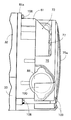
1 to 9 show an embodiment of the present invention. FIG. 1 is an overall side view of a scooter type motorcycle, FIG. 2 is a sectional view taken along line 2-2 of FIG. 1, and FIG. 3 is a side view corresponding to FIG. 3 with the radiator cover removed, FIG. 5 is a sectional view taken along line 5-5 in FIG. 3, and FIG. 6 is a sectional view taken along line 6-6 in FIG. 7 is a perspective view showing a state in which a radiator cover is attached to the radiator, and FIG. 9 is a side view showing a modification of the means for detecting the crank angle position of the crankshaft. .
[0020]
First, in FIG. 1, a vehicle body frame F of a scooter-type motorcycle V including a front wheel Wf that is steered by a
[0021]
The power unit P includes a water-cooled single-cylinder four-cycle engine E and a belt-type continuously variable transmission T extending from the left side surface of the engine E to the rear of the vehicle body, and the rear upper surface of the continuously variable transmission T has a
[0022]
2 to 4, the
[0023]
Such an
[0024]
The belt-type continuously variable transmission T includes a
[0025]
A
[0026]
A driven
[0027]
An
[0028]
Thus, the rotational power of the
[0029]
Since the centrifugal force acting on the centrifugal weight 57 of the
[0030]
Referring also to FIG. 5, a
[0031]
The
[0032]
The
[0033]
6 and 8, the
[0034]
The
[0035]
A
[0036]
A
[0037]
Such a
[0038]
Further, when the
[0039]
One end of a flexible
[0040]
The
[0041]
One end of a flexible
[0042]
The
[0043]
A flexible
[0044]
Further, one end of a flexible
[0045]
3, 6, and 7, the
[0046]
In FIG. 4, the
[0047]
Next, the operation of this embodiment will be described.
[0048]
In a state where the warm-up operation of the engine E has been completed, the cooling water discharged from the
[0049]
By the way, since the upper and
[0050]
That is, the
[0051]
In addition, since the
[0052]
In particular, the
[0053]
In addition, the
[0054]
Further, since the
[0055]
As mentioned above, although the Example of this invention was described, this invention is not limited to the said Example, A various design change can be performed in the range which does not deviate from the summary of this invention. For example, the
[0056]
【The invention's effect】
As described above, the first of the present inventionAnd each secondAccording to the featuresBecause the radiator was attached to the engine via an elastic shroud that induces cooling air for the radiator,In addition to the original function of the shroud inducing the cooling air of the radiator, the anti-vibration function that blocks the transmission of vibrations from the engine to the radiator is eliminated, eliminating the need for a dedicated anti-vibration means for the radiator and simplifying the structure. In turn, the cost can be greatly reduced.
[0057]
In particular, according to the first feature of the present invention, the shroud that surrounds the outer periphery of the cooling fan of the engine is provided with a plurality of discharge ports that can discharge the cooling air that has passed through the radiator outward in the radial direction of the cooling fan. The cooling air that has passed through the radiator can be discharged from these discharge ports.
[0058]
According to the second feature of the present invention,, LaSince the radiator is attached to the engine of the power unit that is swingably coupled to the vehicle body frame via the pivot shaft and supported via the rear cushion, the weight reduction of the radiator and the shroud is as described above. This can reduce the unsprung load and contribute to improving the riding comfort of the vehicle.The radiator is formed in a horizontally long shape in which each tank is longer than the distance between the first and second tanks, and the water jacket inlet of the cylinder block is provided at each end of the first and second tanks near the cylinder head. And a connection to the outlet.
[0059]
Furthermore, according to the third feature of the present invention, the first and second tanks of the radiator are made of lightweight synthetic resin, so that the weight of the radiator can be greatly reduced. In addition, such weight reduction of the radiator can reduce the load capacity of the shroud, thereby reducing its thickness and further improving the vibration isolation function and reducing the weight.
[0060]
Furthermore, according to the fourth aspect of the present invention, the shroud is fixed to the engine by a fastening member, and both ends of a conduit communicating between the radiator and the water jacket are connected to the radiator and the engine. The fastening member is fitted in the fastening direction of the fastening member, so that the fitting state between the shroud and the engine body by the fastening member and the connection hole of the conduit can be maintained at the same time. This eliminates the need to apply and simplifies the piping structure.
[0061]
Furthermore, according to the fifth feature of the present invention, in addition to the first or second feature, the radiator and the shroud are coupled by a rivet, so that an assembly of the radiator and the shroud is formed, and Assembling performance can be improved.
[Brief description of the drawings]
FIG. 1 is an overall side view of a scooter type motorcycle including a vehicle radiator device of the present invention.
FIG. 2 is a cross-sectional view taken along line 2-2 of FIG.
FIG. 3 is a view taken along arrow 3-3 in FIG. 2;
FIG. 4 is a side view corresponding to FIG. 3 with a radiator cover removed.
5 is a cross-sectional view taken along line 5-5 of FIG.
Fig. 2 is a longitudinal plan view of a main part of an engine in the motorcycle.
6 is a sectional view taken along line 6-6 in FIG. 3;
7 is a view taken in the direction of arrow 7 in FIG. 3;
FIG. 8 is a perspective view showing a state in which a radiator cover is attached to the radiator.
FIG. 9 is a side view showing a modification of the means for detecting the crank angle position of the crankshaft.
[Explanation of symbols]
E ・ ・ ・ ・ ・ ・ Engine
F ... Body frame
P ・ ・ ・ ・ ・ ・ Power unit
15 ... Pivot shaft
20 ... Rear cushion
72 ... Radiator
77 ... 2nd tank (upper tank)
78 ... 1st tank (lower tank)
79 ・ ・ ・ ・ ・ Heat dissipation core
81 .. shroud
82 ... Water jacket
82i ... Water jacket entrance
82o ... Water jacket exit
92 .. conduit (second conduit)
107 ··· Rivet
108... Fastening member (bolt)
115 ... ・ Connection hole
116... Connection hole
Claims (6)
前記ラジエータ(72)を、エンジン(E)の冷却ファン(71)外周を囲繞し且つ該ラジエータ(72)の冷却風を誘導する弾性材製のシュラウド(81)を介してエンジン(E)に取り付け、そのシュラウド(81)には、ラジエータ(72)を通過した冷却風を前記冷却ファン(71)の径方向外方に排出し得る複数の排出口(76)が設けられることを特徴とする、車両用ラジエータ装置。A radiator (72) formed by connecting the first and second tanks ( 78, 77 ) via a heat radiating core (79) to the engine (E) of the power unit (P) supported by the vehicle body frame (F). The first tank (78) communicates with the inlet (82i) of the water jacket (82) of the engine (E), and the second tank (77) communicates with the outlet (82o) of the water jacket (82). In the vehicle radiator device,
The radiator (72) is attached to the engine (E) via a shroud (81) made of an elastic material that surrounds the outer periphery of the cooling fan (71) of the engine (E) and guides cooling air of the radiator (72). The shroud (81) is provided with a plurality of discharge ports (76) through which cooling air that has passed through the radiator (72) can be discharged radially outward of the cooling fan (71) . Radiator device for vehicles.
前記ラジエータ(72)を、このラジエータ(72)の冷却風を誘導する弾性材製のシュラウド(81)を介してエンジン(E)に取り付け、
前記ラジエータ(72)は、前記第1及び第2タンク(78,77)の相互間距離よりも各タンク(77、78)が長い横長形状に形成され、その第1及び第2タンク(77、78)の、シリンダヘッド(34)寄りの各端部に前記接続部(89,115)がそれぞれ設けられることを特徴とする、車両用ラジエータ装置。The body frame (F) the power unit (P) is through upper and lower swingably connected to Rutotomoni rear cushion (20) via a pivot shaft (15) supported in the engine (E) of the power unit (P) , the crank case side of the first and second tanks (78,77) between the heat radiation core (79) fitted with a radiator (72) formed by connecting through a Rutotomoni, the engine and the radiator (72) (E) The connection portion (89) of the first tank (78) is connected to the inlet (82i) of the water jacket (82) provided in the cylinder block (32a ) of the engine (E) , and the water jacket (82 In the vehicle radiator device in which the connection part (115) of the second tank (77) communicates with the outlet (82o) of
The radiator (72) is attached to the engine (E) via a shroud (81) made of an elastic material for guiding the cooling air of the radiator (72) .
In the radiator (72), each tank (77, 78) is formed in a horizontally long shape longer than the distance between the first and second tanks (78, 77), and the first and second tanks (77, 78) are formed. 78) The radiator for a vehicle according to claim 78, wherein the connecting portions (89, 115) are provided at respective end portions near the cylinder head (34) .
前記ラジエータ(72)の第1及び第2タンク(77、78)を合成樹脂製としたことを特徴とする、車両用ラジエータ装置。In the radiator device for vehicles according to claim 1 or 2,
A radiator device for a vehicle, wherein the first and second tanks (77, 78) of the radiator (72) are made of synthetic resin.
前記シュラウド(81)をエンジン(E)に締め付け部材(108)により固着し、前記ラジエータ(72)及び前記ウォータジャケット(82)間を連通する導管(92)の両端部を、前記ラジエータ(72)及びエンジン(E)に設けられた接続孔(115,116)に前記締め付け部材(108)の締め付け方向で嵌合したことを特徴とする、車両用ラジエータ装置。In the radiator device for vehicles according to claim 1 or 2,
The shroud (81) is fixed to the engine (E) by a fastening member (108), and both ends of a conduit (92) communicating between the radiator (72) and the water jacket (82) are connected to the radiator (72). And the radiator device for vehicles characterized by fitting to the connection hole (115,116) provided in the engine (E) by the fastening direction of the said fastening member (108).
前記ラジエータ(72)及び前記シュラウド(81)間をリベット(107)により結合したことを特徴とする、車両用ラジエータ装置。In the radiator device for vehicles in any one of Claims 1-3,
A radiator for a vehicle, wherein the radiator (72) and the shroud (81) are coupled by a rivet (107).
前記エンジン(E)のシリンダブロック(32a)が前記クランクケースよりも車体前側に配置されていると共に、そのシリンダボア(41)の軸線(L)が車体前上がりに傾斜していることを特徴とする、車両用ラジエータ装置。The cylinder block (32a) of the engine (E) is disposed on the front side of the vehicle body relative to the crankcase, and the axis (L) of the cylinder bore (41) is inclined upward in the vehicle body. , Radiator device for vehicles.
Priority Applications (6)
| Application Number | Priority Date | Filing Date | Title |
|---|---|---|---|
| JP2000403153A JP3696508B2 (en) | 2000-12-28 | 2000-12-28 | Radiator device for vehicle |
| CNB011193581A CN1201072C (en) | 2000-12-28 | 2001-05-30 | Radiating apparatus for vehicle |
| ES200102814A ES2204259A1 (en) | 2000-12-28 | 2001-12-18 | Vehicle radiator device |
| IT2001TO001199A ITTO20011199A1 (en) | 2000-12-28 | 2001-12-20 | RADIATOR GROUP FOR A VEHICLE. |
| US10/024,560 US6971438B2 (en) | 2000-12-28 | 2001-12-21 | Vehicle radiator device |
| TW090132192A TW544486B (en) | 2000-12-28 | 2001-12-25 | Vehicle radiator device |
Applications Claiming Priority (1)
| Application Number | Priority Date | Filing Date | Title |
|---|---|---|---|
| JP2000403153A JP3696508B2 (en) | 2000-12-28 | 2000-12-28 | Radiator device for vehicle |
Related Child Applications (1)
| Application Number | Title | Priority Date | Filing Date |
|---|---|---|---|
| JP2004295766A Division JP3652696B2 (en) | 2004-10-08 | 2004-10-08 | Radiator device for vehicle |
Publications (3)
| Publication Number | Publication Date |
|---|---|
| JP2002201938A JP2002201938A (en) | 2002-07-19 |
| JP2002201938A5 JP2002201938A5 (en) | 2005-06-23 |
| JP3696508B2 true JP3696508B2 (en) | 2005-09-21 |
Family
ID=18867326
Family Applications (1)
| Application Number | Title | Priority Date | Filing Date |
|---|---|---|---|
| JP2000403153A Expired - Fee Related JP3696508B2 (en) | 2000-12-28 | 2000-12-28 | Radiator device for vehicle |
Country Status (6)
| Country | Link |
|---|---|
| US (1) | US6971438B2 (en) |
| JP (1) | JP3696508B2 (en) |
| CN (1) | CN1201072C (en) |
| ES (1) | ES2204259A1 (en) |
| IT (1) | ITTO20011199A1 (en) |
| TW (1) | TW544486B (en) |
Cited By (3)
| Publication number | Priority date | Publication date | Assignee | Title |
|---|---|---|---|---|
| JP2008175086A (en) * | 2007-01-16 | 2008-07-31 | Honda Motor Co Ltd | Radiator device for vehicle |
| EP2014890A1 (en) | 2007-07-12 | 2009-01-14 | HONDA MOTOR CO., Ltd. | Cooling system of engine for small-sized vehicle |
| JP2009019581A (en) * | 2007-07-12 | 2009-01-29 | Honda Motor Co Ltd | Cooling system of engine for small vehicle |
Families Citing this family (42)
| Publication number | Priority date | Publication date | Assignee | Title |
|---|---|---|---|---|
| TWI254006B (en) * | 2002-06-17 | 2006-05-01 | Yamaha Motor Co Ltd | Air intake device for scooter-type two-wheeled motor vehicle |
| JP4251904B2 (en) * | 2003-04-03 | 2009-04-08 | サンデン株式会社 | Heat exchanger |
| JP4544509B2 (en) * | 2003-10-16 | 2010-09-15 | ヤマハ発動機株式会社 | Water cooling device for saddle riding type vehicle and saddle riding type vehicle |
| US7188696B2 (en) * | 2004-02-17 | 2007-03-13 | Honda Motor Co., Ltd. | Motorcycle with a rear-mounted radiator |
| US7159682B2 (en) * | 2004-06-24 | 2007-01-09 | Honda Motor Co., Ltd. | Motorcycle with improved thermostat mounting |
| US7353898B1 (en) | 2005-02-24 | 2008-04-08 | Polaris Industries Inc. | Integrated heat exchanger and engine mount for a snowmobile |
| JP4596996B2 (en) * | 2005-07-05 | 2010-12-15 | 本田技研工業株式会社 | Cooling structure for vehicle power unit |
| US7422081B2 (en) * | 2005-07-21 | 2008-09-09 | Dufresne Michael C | Grille for a motorcycle radiator cover |
| US20070163243A1 (en) * | 2006-01-17 | 2007-07-19 | Arvin Technologies, Inc. | Exhaust system with cam-operated valve assembly and associated method |
| US7874349B2 (en) * | 2006-03-16 | 2011-01-25 | Visteon Global Technologies, Inc. | Heat exchanger tank |
| JP4582035B2 (en) * | 2006-03-27 | 2010-11-17 | 株式会社デンソー | Motorcycle heat exchanger and method of manufacturing the same |
| JP2008024291A (en) * | 2006-06-23 | 2008-02-07 | Yamaha Motor Co Ltd | Saddle-riding type vehicle |
| JP4871223B2 (en) * | 2006-09-14 | 2012-02-08 | 本田技研工業株式会社 | Water-cooled internal combustion engine equipped with a radiator |
| JP4922080B2 (en) * | 2006-09-20 | 2012-04-25 | 本田技研工業株式会社 | Vehicle-mounted internal combustion engine with exhaust duct |
| JP4939190B2 (en) * | 2006-11-30 | 2012-05-23 | 本田技研工業株式会社 | Power unit for small vehicles |
| JP2008284992A (en) * | 2007-05-17 | 2008-11-27 | Yamaha Motor Co Ltd | Radiator cover for straddle-type vehicle and straddle-type vehicle equipped with the radiator cover |
| US7654357B2 (en) * | 2007-07-02 | 2010-02-02 | Buell Motorcycle Company | Radiator coil mounted on a motorcycle |
| US20090008179A1 (en) * | 2007-07-02 | 2009-01-08 | Erik Buell | Motorcycle having a rotatably-mounted engine |
| JP2009090914A (en) * | 2007-10-11 | 2009-04-30 | Yamaha Motor Co Ltd | Motorcycle |
| BRPI0804646B1 (en) * | 2007-10-30 | 2019-06-04 | Yamaha Hatsudoki Kabushiki Kaisha | RADIATOR COVER FOR MOUNTING VEHICLE, AND MOUNTING VEHICLE WITH THE SAME |
| JP4996521B2 (en) * | 2008-03-28 | 2012-08-08 | 本田技研工業株式会社 | Radiator reserve tank arrangement structure for motorcycles |
| JP2010076751A (en) * | 2008-08-29 | 2010-04-08 | Yamaha Motor Co Ltd | Motorcycle |
| JP5189008B2 (en) * | 2009-02-19 | 2013-04-24 | 本田技研工業株式会社 | Crankcase structure of internal combustion engine |
| KR101387673B1 (en) * | 2009-09-03 | 2014-04-22 | 혼다 기켄 고교 가부시키가이샤 | Cooling air intake structure for v-belt drive continuously variable transmission |
| IN2012DN01851A (en) * | 2009-09-03 | 2015-08-21 | Honda Motor Co Ltd | |
| EP2531394B1 (en) | 2010-02-01 | 2015-07-08 | Polaris Industries Inc. | Vehicle cooling system |
| JP5703183B2 (en) * | 2011-09-25 | 2015-04-15 | 本田技研工業株式会社 | Scooter type motorcycle |
| JP5591778B2 (en) * | 2011-09-28 | 2014-09-17 | 本田技研工業株式会社 | vehicle |
| JP5829907B2 (en) * | 2011-12-28 | 2015-12-09 | 川崎重工業株式会社 | Saddle riding vehicle |
| JP5893459B2 (en) * | 2012-03-22 | 2016-03-23 | 本田技研工業株式会社 | Fuel tank and radiator arrangement structure for saddle-ride type vehicles |
| WO2014005198A1 (en) * | 2012-07-06 | 2014-01-09 | Skoot Logistics Australia Pty Limited | A scooter vehicle with integrated pillion transport container |
| JP6512967B2 (en) * | 2015-07-02 | 2019-05-15 | 株式会社クボタ | Work vehicle |
| ITUB20155584A1 (en) * | 2015-11-13 | 2017-05-13 | Piaggio & C Spa | Engine cooling system of a motor vehicle |
| JP6649083B2 (en) * | 2015-12-28 | 2020-02-19 | 川崎重工業株式会社 | Motorcycle |
| JP6631264B2 (en) * | 2016-01-15 | 2020-01-15 | スズキ株式会社 | Cooling structure of internal combustion engine |
| ES2901612T3 (en) | 2016-11-04 | 2022-03-23 | Piaggio & C Spa | motorcycle engine cooling system |
| US10639985B2 (en) * | 2017-05-15 | 2020-05-05 | Polaris Industries Inc. | Three-wheeled vehicle |
| US10550754B2 (en) | 2017-05-15 | 2020-02-04 | Polaris Industries Inc. | Engine |
| USD904227S1 (en) | 2018-10-26 | 2020-12-08 | Polaris Industries Inc. | Headlight of a three-wheeled vehicle |
| TWI739347B (en) * | 2020-03-17 | 2021-09-11 | 光陽工業股份有限公司 | locomotive |
| JP7415818B2 (en) * | 2020-06-25 | 2024-01-17 | スズキ株式会社 | saddle type vehicle |
| CN113879438A (en) * | 2020-07-03 | 2022-01-04 | 光阳工业股份有限公司 | Motorcycle with a motorcycle body |
Family Cites Families (30)
| Publication number | Priority date | Publication date | Assignee | Title |
|---|---|---|---|---|
| DE1031680B (en) | 1955-04-27 | 1958-06-04 | Erich May | Footwear with a springy heel insert |
| US3775972A (en) * | 1972-01-31 | 1973-12-04 | Garrett Corp | Heat exchanger mounting |
| US3799128A (en) * | 1973-03-08 | 1974-03-26 | Gen Motors Corp | Engine cooling system radiator and fan shroud |
| FR2226032A5 (en) * | 1973-04-11 | 1974-11-08 | Chausson Usines Sa | |
| DE2540040C3 (en) * | 1975-09-09 | 1979-06-07 | Motoren- Und Turbinen-Union Friedrichshafen Gmbh, 7990 Friedrichshafen | Ventilation arrangement for an engine room |
| DE2922695C2 (en) * | 1979-06-02 | 1985-09-12 | Bayerische Motoren Werke AG, 8000 München | Liquid-cooled multi-cylinder internal combustion engine for motorcycles |
| US4295521A (en) * | 1979-09-27 | 1981-10-20 | Caterpillar Tractor Co. | Heat exchanger core mounting apparatus |
| FR2499704B1 (en) * | 1981-02-12 | 1986-08-14 | Valeo | HEAT EXCHANGER AND ITS WATER BOX DEVICE AND EXPANSION VESSEL |
| JPS60185887U (en) * | 1984-05-18 | 1985-12-09 | 東洋ラジエ−タ−株式会社 | Bracket structure for heat exchanger installation |
| JPS6167022U (en) * | 1984-10-05 | 1986-05-08 | ||
| JPH0681898B2 (en) * | 1985-11-18 | 1994-10-19 | 本田技研工業株式会社 | Engine cooling system |
| GB2184700B (en) | 1985-12-23 | 1988-12-07 | Iveco Fiat | Motor vehicle having a tilting radiator |
| US4828017A (en) * | 1986-10-23 | 1989-05-09 | Honda Giken Kogyo Kabushiki Kaisha | Cooling device for off-road vehicle |
| US5307865A (en) * | 1987-02-06 | 1994-05-03 | Honda Giken Kogyo Kabushiki Kaisha | Engine oil cooling system |
| US5145023A (en) * | 1988-06-10 | 1992-09-08 | Honda Giken Kogyo Kabushiki Kaisha | Motorcycle fuel tank providing multiple enhancements |
| JP2649179B2 (en) * | 1988-12-30 | 1997-09-03 | ヤマハ発動機株式会社 | Air-liquid cooling engine |
| US5267624A (en) * | 1991-11-05 | 1993-12-07 | Paccar Inc. | Winter front assembly for charge air cooled trucks and method |
| RU2059842C1 (en) | 1993-02-11 | 1996-05-10 | Вадим Витальевич Маслаев | Liquid cooling system for internal combustion engine |
| JPH084530A (en) | 1994-06-23 | 1996-01-09 | Aisin Chem Co Ltd | Cooling fan shroud device |
| JP3195502B2 (en) | 1994-10-11 | 2001-08-06 | 日野自動車株式会社 | Radiator tank made of fiber reinforced resin and method of manufacturing the same |
| JP2612430B2 (en) * | 1995-01-30 | 1997-05-21 | カルソニック株式会社 | Mounting of radiator, resin lower tank of radiator, method of manufacturing the same, and mold for manufacturing the same |
| JP3409496B2 (en) * | 1995-03-30 | 2003-05-26 | 日産自動車株式会社 | Radiator structure |
| DE19526286A1 (en) * | 1995-07-19 | 1997-01-23 | Behr Gmbh & Co | Heat exchanger |
| JP3633083B2 (en) * | 1996-03-05 | 2005-03-30 | 本田技研工業株式会社 | Arrangement structure of radiator and oil cooler in motorcycle |
| US5865244A (en) * | 1997-03-25 | 1999-02-02 | Behr America, Inc. | Plastic header tank matrix and method of making same |
| JPH1199964A (en) * | 1997-09-29 | 1999-04-13 | Aisin Seiki Co Ltd | Vehicle front end module structure |
| JP3601807B2 (en) * | 1997-10-08 | 2004-12-15 | 本田技研工業株式会社 | Radiator cooling system for motorcycles |
| JP3980163B2 (en) * | 1998-03-31 | 2007-09-26 | 本田技研工業株式会社 | Heat exchanger |
| JP4149614B2 (en) * | 1999-05-27 | 2008-09-10 | 本田技研工業株式会社 | Air cleaner arrangement structure for motorcycles |
| JP4303361B2 (en) | 1999-06-07 | 2009-07-29 | 本田技研工業株式会社 | Scooter type vehicle |
-
2000
- 2000-12-28 JP JP2000403153A patent/JP3696508B2/en not_active Expired - Fee Related
-
2001
- 2001-05-30 CN CNB011193581A patent/CN1201072C/en not_active Expired - Lifetime
- 2001-12-18 ES ES200102814A patent/ES2204259A1/en active Pending
- 2001-12-20 IT IT2001TO001199A patent/ITTO20011199A1/en unknown
- 2001-12-21 US US10/024,560 patent/US6971438B2/en not_active Expired - Lifetime
- 2001-12-25 TW TW090132192A patent/TW544486B/en not_active IP Right Cessation
Cited By (4)
| Publication number | Priority date | Publication date | Assignee | Title |
|---|---|---|---|---|
| JP2008175086A (en) * | 2007-01-16 | 2008-07-31 | Honda Motor Co Ltd | Radiator device for vehicle |
| EP2014890A1 (en) | 2007-07-12 | 2009-01-14 | HONDA MOTOR CO., Ltd. | Cooling system of engine for small-sized vehicle |
| JP2009019581A (en) * | 2007-07-12 | 2009-01-29 | Honda Motor Co Ltd | Cooling system of engine for small vehicle |
| CN101344030B (en) * | 2007-07-12 | 2011-10-05 | 本田技研工业株式会社 | Cooling system of engine for small-sized vehicle |
Also Published As
| Publication number | Publication date |
|---|---|
| TW544486B (en) | 2003-08-01 |
| US6971438B2 (en) | 2005-12-06 |
| ITTO20011199A1 (en) | 2003-06-20 |
| ITTO20011199A0 (en) | 2001-12-20 |
| US20020112680A1 (en) | 2002-08-22 |
| CN1361354A (en) | 2002-07-31 |
| ES2204259A1 (en) | 2004-04-16 |
| CN1201072C (en) | 2005-05-11 |
| JP2002201938A (en) | 2002-07-19 |
Similar Documents
| Publication | Publication Date | Title |
|---|---|---|
| JP3696508B2 (en) | Radiator device for vehicle | |
| US7784586B2 (en) | Noise reduction structure for hybrid vehicle | |
| US7327240B2 (en) | Indicator device for motor driven vehicle | |
| JP3907903B2 (en) | Cooling water circulation structure of internal combustion engine | |
| JP3894728B2 (en) | Timing transmission device for valve train in engine | |
| JP4163314B2 (en) | Swing power unit for vehicles | |
| JP3777298B2 (en) | Radiator mounting structure in vehicles | |
| JP3819700B2 (en) | Radiator device for vehicle | |
| CN112172984B (en) | Radiator structure of saddle-type vehicle | |
| EP2014891B1 (en) | Radiator for small-sized vehicle | |
| KR100367974B1 (en) | Swing-typed power unit | |
| JP3652696B2 (en) | Radiator device for vehicle | |
| JP2000344168A (en) | Filler neck fitting structure for radiator in motorcycle | |
| JP3686077B2 (en) | Radiator device for vehicle | |
| JP4441389B2 (en) | Exhaust muffler structure in motorcycles | |
| JP7022219B2 (en) | Internal combustion engine | |
| JP4106962B2 (en) | Structure around balancer shaft in internal combustion engine | |
| JP7019831B2 (en) | Internal combustion engine | |
| JP2003314277A (en) | Cooling device of power unit | |
| JP3388244B2 (en) | Motorcycles and tricycles | |
| JP6682803B2 (en) | Saddle type vehicle | |
| JPH05179944A (en) | Engine cooling device of motorcycle | |
| JP2004353482A (en) | Cooling structure of engine for snowmobile |
Legal Events
| Date | Code | Title | Description |
|---|---|---|---|
| A521 | Request for written amendment filed |
Free format text: JAPANESE INTERMEDIATE CODE: A523 Effective date: 20041001 |
|
| A871 | Explanation of circumstances concerning accelerated examination |
Free format text: JAPANESE INTERMEDIATE CODE: A871 Effective date: 20041001 |
|
| A975 | Report on accelerated examination |
Free format text: JAPANESE INTERMEDIATE CODE: A971005 Effective date: 20041022 |
|
| A977 | Report on retrieval |
Free format text: JAPANESE INTERMEDIATE CODE: A971007 Effective date: 20050126 |
|
| A131 | Notification of reasons for refusal |
Free format text: JAPANESE INTERMEDIATE CODE: A131 Effective date: 20050209 |
|
| A521 | Request for written amendment filed |
Free format text: JAPANESE INTERMEDIATE CODE: A523 Effective date: 20050411 |
|
| TRDD | Decision of grant or rejection written | ||
| A01 | Written decision to grant a patent or to grant a registration (utility model) |
Free format text: JAPANESE INTERMEDIATE CODE: A01 Effective date: 20050608 |
|
| A61 | First payment of annual fees (during grant procedure) |
Free format text: JAPANESE INTERMEDIATE CODE: A61 Effective date: 20050629 |
|
| R150 | Certificate of patent or registration of utility model |
Ref document number: 3696508 Country of ref document: JP Free format text: JAPANESE INTERMEDIATE CODE: R150 Free format text: JAPANESE INTERMEDIATE CODE: R150 |
|
| FPAY | Renewal fee payment (event date is renewal date of database) |
Free format text: PAYMENT UNTIL: 20080708 Year of fee payment: 3 |
|
| FPAY | Renewal fee payment (event date is renewal date of database) |
Free format text: PAYMENT UNTIL: 20090708 Year of fee payment: 4 |
|
| FPAY | Renewal fee payment (event date is renewal date of database) |
Free format text: PAYMENT UNTIL: 20100708 Year of fee payment: 5 |
|
| FPAY | Renewal fee payment (event date is renewal date of database) |
Free format text: PAYMENT UNTIL: 20100708 Year of fee payment: 5 |
|
| FPAY | Renewal fee payment (event date is renewal date of database) |
Free format text: PAYMENT UNTIL: 20110708 Year of fee payment: 6 |
|
| FPAY | Renewal fee payment (event date is renewal date of database) |
Free format text: PAYMENT UNTIL: 20110708 Year of fee payment: 6 |
|
| FPAY | Renewal fee payment (event date is renewal date of database) |
Free format text: PAYMENT UNTIL: 20120708 Year of fee payment: 7 |
|
| FPAY | Renewal fee payment (event date is renewal date of database) |
Free format text: PAYMENT UNTIL: 20120708 Year of fee payment: 7 |
|
| FPAY | Renewal fee payment (event date is renewal date of database) |
Free format text: PAYMENT UNTIL: 20130708 Year of fee payment: 8 |
|
| FPAY | Renewal fee payment (event date is renewal date of database) |
Free format text: PAYMENT UNTIL: 20140708 Year of fee payment: 9 |
|
| LAPS | Cancellation because of no payment of annual fees |