JP2008024291A - Saddle-riding type vehicle - Google Patents
Saddle-riding type vehicle Download PDFInfo
- Publication number
- JP2008024291A JP2008024291A JP2007140778A JP2007140778A JP2008024291A JP 2008024291 A JP2008024291 A JP 2008024291A JP 2007140778 A JP2007140778 A JP 2007140778A JP 2007140778 A JP2007140778 A JP 2007140778A JP 2008024291 A JP2008024291 A JP 2008024291A
- Authority
- JP
- Japan
- Prior art keywords
- heat shield
- shield cover
- reserve tank
- exhaust pipe
- engine
- Prior art date
- Legal status (The legal status is an assumption and is not a legal conclusion. Google has not performed a legal analysis and makes no representation as to the accuracy of the status listed.)
- Pending
Links
Images


Classifications
-
- B—PERFORMING OPERATIONS; TRANSPORTING
- B62—LAND VEHICLES FOR TRAVELLING OTHERWISE THAN ON RAILS
- B62J—CYCLE SADDLES OR SEATS; AUXILIARY DEVICES OR ACCESSORIES SPECIALLY ADAPTED TO CYCLES AND NOT OTHERWISE PROVIDED FOR, e.g. ARTICLE CARRIERS OR CYCLE PROTECTORS
- B62J23/00—Other protectors specially adapted for cycles
-
- B—PERFORMING OPERATIONS; TRANSPORTING
- B62—LAND VEHICLES FOR TRAVELLING OTHERWISE THAN ON RAILS
- B62K—CYCLES; CYCLE FRAMES; CYCLE STEERING DEVICES; RIDER-OPERATED TERMINAL CONTROLS SPECIALLY ADAPTED FOR CYCLES; CYCLE AXLE SUSPENSIONS; CYCLE SIDE-CARS, FORECARS, OR THE LIKE
- B62K11/00—Motorcycles, engine-assisted cycles or motor scooters with one or two wheels
- B62K11/02—Frames
- B62K11/04—Frames characterised by the engine being between front and rear wheels
Abstract
Description
本発明は、後輪と、後輪を駆動するエンジンと、エンジンに連結され、エンジンから後方に向けて設けられる排気管と、前方からの走行風を受けるラジエターと、操縦者が着座するシートと、シートの下方に配置され、排気管の車幅方向内側に設けられるリザーブタンクとを備える鞍乗型車両に関する。 The present invention includes a rear wheel, an engine that drives the rear wheel, an exhaust pipe that is connected to the engine and is provided rearward from the engine, a radiator that receives traveling wind from the front, and a seat on which a driver is seated. The present invention relates to a straddle-type vehicle including a reserve tank that is disposed below a seat and provided on an inner side of an exhaust pipe in a vehicle width direction.
従来、後輪を駆動するエンジンと、エンジンに連結され、エンジンから後方に向けて設けられる排気管と、ラジエターと、ラジエターの冷却水を蓄えるリザーブタンクとを備える鞍乗型車両が、存在する(例えば、特許文献1参照)。 Conventionally, there is a straddle-type vehicle including an engine that drives a rear wheel, an exhaust pipe that is connected to the engine and is provided rearward from the engine, a radiator, and a reserve tank that stores cooling water of the radiator ( For example, see Patent Document 1).
このような鞍乗型車両において、リザーブタンクの容量が大きい場合、リザーブタンクは、リザーブタンクを露出させないために、大きなスペースを確保できるシートの下方に配置され、排気管の車幅方向内側に設けられる。
しかしながら、上述した鞍乗型車両の排気管は、エンジンから排気される高温のガスにより、リザーブタンクに熱の影響を及ぼすという問題点があった。 However, the above-described exhaust pipe of the saddle-ride type vehicle has a problem that heat is exerted on the reserve tank by the high-temperature gas exhausted from the engine.
なお、排気管からリザーブタンクに伝播する熱を低減するために、例えば、排気管とリザーブタンクとを離間して、排気管からの熱が伝播しない程度の距離を保つことが考えられるが、シート下に配置されたリザーブタンク周辺の車幅方向のサイズが大きくなるため、操縦者の足つき性を低下させる場合があった。 In order to reduce the heat transmitted from the exhaust pipe to the reserve tank, for example, it is conceivable that the exhaust pipe and the reserve tank are separated from each other to maintain a distance that does not allow the heat from the exhaust pipe to propagate. Since the size in the vehicle width direction around the reserve tank arranged underneath is increased, the driver's footing may be reduced.
そこで、本発明は、上述の課題に鑑みてなされたものであり、シートの下方で、排気管の車幅方向内側にリザーブタンクを備える場合においても、排気管からリザーブタンクへ伝播する熱を低減できる鞍乗型車両を提供することを目的とする。 Therefore, the present invention has been made in view of the above-described problems, and even when a reserve tank is provided on the inner side in the vehicle width direction of the exhaust pipe below the seat, heat transmitted from the exhaust pipe to the reserve tank is reduced. An object is to provide a straddle-type vehicle that can be used.
上述した問題を解決するため、本発明は、次のような特徴を有している。まず、本発明の第1の特徴は、後輪(後輪40)と、前記後輪を駆動するエンジン(エンジン30)と、前記エンジンに接続され、前記エンジンから後方に向けて延出する排気管(例えば、排気管31)と、前記エンジンの前方に配置され、走行風を受けるラジエター(ラジエター70)と、前記エンジンの後方に配置され、操縦者が着座するシート(シート71)と、前記シートの下方かつ前記排気管の車幅方向内側に配置され、前記ラジエターの冷却水を貯留するリザーブタンク(例えば、リザーブタンク34)とを備える鞍乗型車両であって、前記排気管と前記リザーブタンクとの間に遮熱カバー(例えば、第1遮熱カバー32)を備えることを要旨とする。 In order to solve the problems described above, the present invention has the following features. First, the first feature of the present invention is that a rear wheel (rear wheel 40), an engine (engine 30) that drives the rear wheel, and an exhaust gas that is connected to the engine and extends rearward from the engine. A pipe (for example, an exhaust pipe 31), a radiator (radiator 70) that is disposed in front of the engine and receives traveling wind, a seat (seat 71) that is disposed behind the engine and is seated by a driver, A straddle-type vehicle that is disposed below a seat and inside the exhaust pipe in the vehicle width direction and includes a reserve tank (for example, a reserve tank 34) that stores cooling water for the radiator, the exhaust pipe and the reserve The gist is to provide a heat shield cover (for example, the first heat shield cover 32) between the tank and the tank.
このような鞍乗型車両によれば、シートの下方で、排気管の車幅方向内側にリザーブタンクを備える場合においても、遮熱カバーは、排気管とリザーブタンクとの間に設けられるため、排気管からリザーブタンクへ伝播する熱を低減できる。 According to such a saddle riding type vehicle, even when the reserve tank is provided below the seat and inside the exhaust pipe in the vehicle width direction, the heat shield cover is provided between the exhaust pipe and the reserve tank. Heat transmitted from the exhaust pipe to the reserve tank can be reduced.
本発明の第2の特徴は、本発明の第1の特徴に係り、前記ラジエターと前記リザーブタンクとに連通するサイフォンチューブ(サイフォンチューブ36a)をさらに備え、前記リザーブタンクは、前記サイフォンチューブの一端に連結される案内管(例えば、案内管341b)を有し、前記サイフォンチューブの一端は、前記案内管の上端に連結されており、前記遮熱カバーは、第1遮熱カバー(第1遮熱カバー32)を含み、前記第1遮熱カバーの上端(第1遮熱カバーの上端32e)は、前記案内管の上端よりも上方に設けられていることを要旨とする。
The second feature of the present invention relates to the first feature of the present invention, further comprising a siphon tube (
本発明の第3の特徴は、本発明の第2の特徴に係り、前記第1遮熱カバーには、開口(サービスホール320)が形成され、前記開口の下端(サービスホール下端320a)は、前記案内管の上端(案内管上端34e)よりも下方に設けられていることを要旨とする。
A third feature of the present invention relates to the second feature of the present invention, wherein an opening (service hole 320) is formed in the first heat shield cover, and a lower end of the opening (service hole lower end 320a) is The gist is that it is provided below the upper end of the guide tube (guide tube
本発明の第4の特徴は、本発明の第3の特徴に係り、前記遮熱カバーは、前記開口(サービスホール320)を覆う第2遮熱カバー(第2遮熱カバー33)を含むことを要旨とする。 A fourth feature of the present invention relates to the third feature of the present invention, wherein the heat shield cover includes a second heat shield cover (second heat shield cover 33) covering the opening (service hole 320). Is the gist.
本発明の第5の特徴は、本発明の第1の特徴に係り、前記ラジエターと前記リザーブタンクとに連通するサイフォンチューブをさらに備え、前記リザーブタンクは、前記サイフォンチューブの一端に連結される案内管を有し、前記サイフォンチューブの一端は、前記案内管の上端に連結されており、 前記遮熱カバーは、第1遮熱カバーを含み、前記第1遮熱カバー(第1遮熱カバー321)の上端(上端321e)は、前記案内管(案内管341b)の上端(案内管上端341e)より下方に設けられていることを要旨とする。
A fifth feature of the present invention relates to the first feature of the present invention, further comprising a siphon tube communicating with the radiator and the reserve tank, wherein the reserve tank is connected to one end of the siphon tube. The siphon tube has one end connected to an upper end of the guide tube, the heat insulating cover includes a first heat insulating cover, and the first heat insulating cover (first
本発明の第6の特徴は、本発明の第1の特徴に係り、前記排気管内(例えば、排気管31T)を流れる排気ガスの状態を検出するセンサーユニット(O2センサーユニット)と、前記センサーユニットと接続される配線(第2配線39)とを備え、前記センサーユニットの一端部(O2センサー本体部37a)は、前記排気管に挿入され、前記センサーユニットの他端部(第1端子部37e)は、遮熱カバー(例えば、第2遮熱カバー33)によって覆われる領域で前記配線と接続されることを要旨とする。
A sixth feature of the present invention relates to the first feature of the present invention, and is a sensor unit (O 2 sensor unit) for detecting a state of exhaust gas flowing in the exhaust pipe (for example, the
本発明の第7の特徴は、本発明の第1の特徴に係り、前記遮熱カバー(例えば、第1遮熱カバー32)は、車両の側面視において、前記リザーブタンク(リザーブタンク34)と前記排気管(排気管31T)とが重複する領域を覆うことを要旨とする。
A seventh feature of the present invention is related to the first feature of the present invention, wherein the heat shield cover (for example, the first heat shield cover 32) is connected to the reserve tank (reserve tank 34) in a side view of the vehicle. The gist is to cover a region where the exhaust pipe (
本発明によれば、シートの下方で、排気管の車幅方向内側にリザーブタンクを備える場合においても、排気管からリザーブタンクへ伝播する熱を低減できる鞍乗型車両を提供することができる。 According to the present invention, it is possible to provide a straddle-type vehicle that can reduce heat propagated from the exhaust pipe to the reserve tank even when the reserve tank is provided below the seat and on the inner side in the vehicle width direction of the exhaust pipe.
次に、本発明に係る鞍乗型車両の実施形態について、図面を参照しながら説明する。なお、以下の図面の記載において、同一または類似の部分には、同一または類似の符号を付している。ただし、図面は模式的なものであり、各寸法の比率などは現実のものとは異なることに留意すべきである。 Next, an embodiment of a saddle riding type vehicle according to the present invention will be described with reference to the drawings. In the following description of the drawings, the same or similar parts are denoted by the same or similar reference numerals. However, it should be noted that the drawings are schematic and ratios of dimensions are different from actual ones.
したがって、具体的な寸法などは以下の説明を参酌して判断すべきものである。また、図面相互間においても互いの寸法の関係や比率が異なる部分が含まれていることは勿論である。 Accordingly, specific dimensions and the like should be determined in consideration of the following description. Moreover, it is a matter of course that portions having different dimensional relationships and ratios are included between the drawings.
(本実施形態に係る鞍乗型車両の全体構成)
図1及び図2を参照して、本実施形態に係る鞍乗型車両である自動二輪車10の全体構成について説明する。図1は、自動二輪車10の左側面図である。また、図2は、自動二輪車10の右側面図である。図3は、自動二輪車10の右側面図の拡大図である。
(Overall configuration of saddle riding type vehicle according to this embodiment)
With reference to FIG.1 and FIG.2, the whole structure of the motorcycle 10 which is a straddle-type vehicle which concerns on this embodiment is demonstrated. FIG. 1 is a left side view of the motorcycle 10. FIG. 2 is a right side view of the motorcycle 10. FIG. 3 is an enlarged view of a right side view of the motorcycle 10.
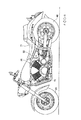
図1に示すように、自動二輪車10は、前輪20及び後輪40を備え、V型のエンジン30を用いて後輪40を駆動する。
As shown in FIG. 1, the motorcycle 10 includes a
図1に示すように、本実施形態に係る自動二輪車10は、両足を前方に投げ出すようなライディングポジションとなる、いわゆるアメリカンタイプの自動二輪車である。 As shown in FIG. 1, the motorcycle 10 according to the present embodiment is a so-called American type motorcycle that assumes a riding position in which both feet are thrown forward.
自動二輪車10は、エンジン30の前方に配置され、走行風を受けるラジエター70と、エンジン30の後方に配置され、ライダーが着座するシート71とを備える。シート71の下方には、リザーブタンク34(図2参照)が備えられる。車体フレーム50は、自動二輪車10の骨格を形成する。車体フレーム50には、エンジン30が取り付けられる。
The motorcycle 10 includes a radiator 70 that is disposed in front of the
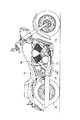
図2に示すように、本実施形態に係る自動二輪車10は、エンジン30に接続され、エンジン30から後方に向けて延出する排気管31と、ラジエター70の冷却水を貯留するリザーブタンク34とを備える。
As shown in FIG. 2, the motorcycle 10 according to this embodiment includes an exhaust pipe 31 that is connected to the
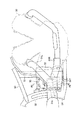
図3に示すように、車体フレーム50、車体フレーム51、車体フレーム52で囲まれる領域において、排気管31と、リザーブタンク34との間には、第1遮熱カバー32が、備えられる。また、本実施形態に係る自動二輪車10は、第2遮熱カバー33を備える。
As shown in FIG. 3, a first
(排気管の構造)
次に、図3を参照して、排気管31の具体的な構造について説明する。
(Exhaust pipe structure)
Next, a specific structure of the exhaust pipe 31 will be described with reference to FIG.
図3に示すように、自動二輪車10には、エンジン30に連結される排気管31L、排気管31Rが設けられている。排気管31は、エンジン30が排出する高温の排気ガスを後方のマフラー(不図示)に誘導する。具体的には、排気管31Rは、V型のエンジン30において、前側バンクの前側から、自動二輪車10の後方に延出している。排気管31Lは、後側バンクの後側から、自動二輪車10の後方に延出している。このように、排気管31は、エンジン30の前側に接続され後方に向けて延出する排気管31Lと、エンジン30の後側に接続され後方に向けて延出する排気管31Rとを含む。また、排気管31Lと、排気管31Rとは、シート71(図1参照)の下方、且つ、車体フレーム51と車体フレーム52の間で一つに集合され、排気管31Tとなる。つまり、排気管31は、排気管31Lと、排気管31Rと、排気管31Tとで構成される。
As shown in FIG. 3, the motorcycle 10 is provided with an exhaust pipe 31 </ b> L and an exhaust pipe 31 </ b> R connected to the
排気管31Tは、自動二輪車10の左側方に沿って、後方に向けて設けられている。車体フレーム51と車体フレーム52の間の排気管31Tには、O2センサーユニット37(図4参照)のO2センサー本体部が設けられている。
The
(リザーブタンクの構造)
次に、図3及び図4を参照して、リザーブタンク34の具体的な構造について説明する。
(Reserve tank structure)
Next, a specific structure of the
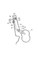
図4は、第1遮熱カバー32及びリザーブタンク34の周囲の右側面図の拡大図である。また、図4では、リザーブタンク34の位置を明確にするために、排気管31を省略した。
FIG. 4 is an enlarged view of a right side view around the first
図3に示すように、排気管31よりも自動二輪車10の車幅方向内側に、リザーブタンク34が設けられる。リザーブタンク34は、排気管31Tの側方に設けられている。
As shown in FIG. 3, a
図4に示すように、リザーブタンク34は、ラジエター70(図1参照)の内部を流れる冷却水を蓄える貯蔵部34aと、冷却水を貯蔵部34aに導く案内管34bとを備える。
As shown in FIG. 4, the
なお、本実施形態における「冷却水」には、エンジン30やラジエター70などの冷却系内を循環する冷却液が含まれる。従って、「冷却水」は、冷却系内において熱の移動を行う冷媒を意味する。
The “cooling water” in the present embodiment includes a coolant that circulates in the cooling system such as the
案内管34bの上端は、冷却水を補給する給水口としての機能を有している。案内管34bの上端である案内管上端34e(図5参照)には、案内管34bの給水口を締めるネジ35が設けられている。また、案内管上端34eには、ラジエター70と接続されるサイフォンチューブ36aと、自動二輪車10の外部に向けられるブリーザーチューブ36bとが、設けられている。
The upper end of the
サイフォンチューブ36aは、ラジエター70とリザーブタンク34とに連通している。冷却水は、サイフォンチューブ36aの内部を流通する。サイフォンチューブ36aの一端は、案内管上端34eに連結されている。サイフォンチューブ36aは、ラジエター70の圧力が一定以上になるとラジエター70からリザーブタンク34へ冷却水を導く。また、サイフォンチューブ36aは、ラジエター70の冷却水が冷えて、負圧になるとリザーブタンク34からラジエター70へ冷却水を戻す。
The siphon
リザーブタンク34は、車体フレーム51(図3参照)に連結されるステー34cと、車体フレーム52に連結されるブラケット53とによって支持されている。
The
具体的には、ステー34c及び車体フレーム52(図3参照)には、取付孔(不図示)が、それぞれ設けられている。ステー34cの取付孔には、車体フレーム52の取付孔を介して連結されるリザーブタンク取付ビス34d(ねじ体)が挿入される。つまり、リザーブタンク34と、車体フレーム52とは、リザーブタンク取付ビス34dを介して連結されている。
Specifically, mounting holes (not shown) are provided in the
ブラケット53には、リベット孔(不図示)が、設けられている。ブラケット53のリベット孔には、リベット留め具55(図6参照)が、挿入されている。リザーブタンク34の底には、リベット54が、設けられている。リベット54は、ブラケット53の固定孔に設けられたリベット留め具55に連結されている。つまり、リザーブタンク34と、ブラケット53とは、リベット54を介して連結されている。
The
(遮熱カバーの構造)
次に、図4及び図5を参照して、遮熱カバー(第1遮熱カバー32、第2遮熱カバー33)の具体的な構造について説明する。図4は、第1遮熱カバー32及びリザーブタンク34の周囲の右側面図の拡大図である。また、図4では、第1遮熱カバー32とリザーブタンク34との位置を明確にするために、第1遮熱カバー32及びリザーブタンク34以外の部品を一部省略した。図5は、第1遮熱カバー32及びリザーブタンク34の右側面図の拡大図である。
(Structure of heat shield cover)
Next, with reference to FIG.4 and FIG.5, the specific structure of the heat shield cover (the 1st
図4に示すように、第1遮熱カバー32は、自動二輪車10の側面視において、排気管31(図3参照)に重なり、排気管31とリザーブタンク34との間に設けられる。第1遮熱カバー32は、自動二輪車10の側面視において、案内管上端34eと重なる位置にサービスホール320を備えている。
As shown in FIG. 4, the first
なお、本実施形態においては、排気管31とリザーブタンク34との間で、車体フレーム52が設けられている領域と、サービスホール320が設けられている領域とを除く、排気管31とリザーブタンク34との間の全ての領域でリザーブタンク34の側方に第1遮熱カバー32が、設けられている。
In the present embodiment, the exhaust pipe 31 and the reserve tank are excluded between the exhaust pipe 31 and the
第1遮熱カバー32は、車体フレーム52に連結されるステー52aと、ステー52bと、ステー52cとによって支持されている。
The first
具体的には、ステー52a及び第1遮熱カバー32には、取付孔(不図示)が、それぞれ設けられている。第1遮熱カバー32の取付孔には、第1遮熱カバー32の取付孔と、ステー52aとを介して連結される第1遮熱カバー取付ビス32a(ねじ体)が挿入される。つまり、第1遮熱カバー32と、ステー52aとは、第1遮熱カバー取付ビス32aを介して連結されている。
Specifically, the
ステー52aと同様にステー52b、ステー52cに対応する第1遮熱カバー32の位置には、取付孔(不図示)が、それぞれ設けられている。つまり、ステー52bと、ステー52cとは、第1遮熱カバー取付ビス32b、第1遮熱カバー取付ビス32cを介してそれぞれ第1遮熱カバー32に連結されている。
Similar to the
第2遮熱カバー33は、自動二輪車10の側面視において、自動二輪車10の側方からサービスホール320を覆う。
The second
第2遮熱カバー33は、第2遮熱カバー取付ビス33a、第2遮熱カバー取付ビス33b、第2遮熱カバー取付ビス33cとを介して、それぞれ第1遮熱カバー32に連結されるステー(図7参照)に連結されている。
The second
また、第2遮熱カバー33は、O2センサーユニット37の第1配線部37bの一部と、O2センサーユニット37の端部であり、第1配線部37bと接続される第1端子部37eと、第1端子部37eと接続される第2端子部39eと、第2端子部39eと接続され自動二輪車10の内部方向に延びる第2配線39の一部とを覆っている。
The second
図5を参照して、第2遮熱カバー33に覆われる領域について更に説明する。
With reference to FIG. 5, the area | region covered with the 2nd
図5に示すように、第2遮熱カバー33に覆われる領域には、メンテナンス用のサービスホール320、第1端子部37eと、第2端子部39eとが設けられている。また、第2遮熱カバー33に覆われる領域には、サービスホール320を介して、リザーブタンク34の案内管34bの案内管上端34eが、自動二輪車10の側方に露出する。
As shown in FIG. 5, a
なお、サイフォンチューブ36aの一端は、案内管の上端に連結され、連結部分はクリップ35aによって留められている。
Note that one end of the siphon
(排気管、リザーブタンク、遮熱カバーの配置関係)
次に、図6を参照して、排気管31、リザーブタンク34、第1遮熱カバー32、第2遮熱カバー33の配置関係について説明する。
(Disposition relationship of exhaust pipe, reserve tank, heat shield cover)
Next, an arrangement relationship among the exhaust pipe 31, the
図6は、図2、図3、図4に示すF6−F6方向の断面図である。具体的には、図6は、リザーブタンク34の案内管上端34eを通る自動二輪車10の車幅方向の断面である案内管断面である。
FIG. 6 is a cross-sectional view in the F6-F6 direction shown in FIG. 2, FIG. 3, and FIG. Specifically, FIG. 6 is a guide tube cross section that is a cross section in the vehicle width direction of the motorcycle 10 that passes through the guide tube
図6に示すように、サービスホール上端320bは、案内管上端34eよりも上方に設けられている。また、サービスホール下端320aは、案内管上端34eよりも下方、且つ排気管上端31eよりも上方に設けられている。
As shown in FIG. 6, the service hole upper end 320b is provided above the guide tube
また、リザーブタンク34の下方のブラケット53には、リベット孔(不図示)が、設けられている。リザーブタンク34の底には、リベット54が、設けられている。ブラケット53のリベット孔には、リベット留め具55が、固定されている。
The
また、第1遮熱カバー32よりも、自動二輪車10の車幅方向内側には、後輪40方向にブレーキフルードで満たされたブレーキホース62が、設けられている。
A
なお、図6に示すように、案内管上端34eには、冷却水が漏れ出ないように封止キャップ35bが取り付けられている。封止キャップ35bに挿通された挿通管35cは、サイフォンチューブ36aと接続され、サイフォンチューブ36aからリザーブタンク34へ冷却水を導き、また、リザーブタンク34からサイフォンチューブ36aへ冷却水を導く。
In addition, as shown in FIG. 6, the sealing
(その他、遮熱カバーの周辺部品の詳細構成)
次に、図7及び図8を参照して、遮熱カバー(第1遮熱カバー32、第2遮熱カバー33)の周辺部品の具体的な構成について説明する。図7は、図3、図4に示すF7−F7方向の断面図である。図8は、第1遮熱カバー32及びリザーブタンク34の周囲の右側面図の拡大図である。また、図8では、遮熱カバーの周辺部品の位置を明確にするために、排気管31を省略し、車体フレーム50、車体フレーム51、車体フレーム52を想像線にて示す。
(In addition, detailed configuration of peripheral parts of the heat shield cover)
Next, with reference to FIG.7 and FIG.8, the specific structure of the peripheral component of the heat shield cover (the 1st
図7に示すように、排気管31T内を流れる排気ガスの状態を検出するO2センサーユニット37の端部であるO2センサー本体部37は、排気管31内に挿入される。O2センサー本体部37は、例えば、排気管31内を流れる排気ガスの温度や酸素濃度を測定する。
As shown in FIG. 7, an O 2 sensor
また、第1遮熱カバー32は、第1遮熱カバー取付ビス32cによって、スペーサー323、第1遮熱カバー32の取付孔(不図示)、ステー52cの取付孔(不図示)、を介して、ビス固定具325に挿入され、固定されている。
Further, the first
また、第2遮熱カバー33は、第2遮熱カバー取付ビス33cによって、第1遮熱カバー32に連結されるステー331cに挿入され、固定されている。
The second
また、第1遮熱カバー32よりも、自動二輪車10の内側には、ブレーキフルードを貯蔵するリザーブタンク63(図8参照)からブレーキフルードで満たされたリザーブホース64が、設けられている。
In addition, a
図8に示すように、第1遮熱カバー32よりも、自動二輪車10の内側には、クラッチレバー(不図示)とクラッチ(不図示)とに接続されるクラッチワイヤ61、ブレーキホース62、リザーブホース64が、設けられている。
As shown in FIG. 8, a
(作用・効果)
以上説明した自動二輪車10によれば、第1遮熱カバー32は、自動二輪車10の排気管31とリザーブタンク34との間に設けられる。
(Action / Effect)
According to the motorcycle 10 described above, the first
これにより、第1遮熱カバー32は、排気管31からリザーブタンク34へ伝播する熱を遮ることができ、排気管31によるリザーブタンク34への熱の影響を低減できる。
Thereby, the 1st
従って、シート71の下方で、排気管31Tの車幅方向内側にリザーブタンク34を備える場合においても、排気管31Tからリザーブタンク34へ伝播する熱を低減できる自動二輪車10を得ることができる。
Therefore, even when the
また、第1遮熱カバー32は、案内管34bの案内管上端34eより上方に設けられており、第1遮熱カバー32には、サービスホール320が形成され、第1遮熱カバーのサービスホール下端320aは、案内管34bの車幅方向の断面において、案内管上端34eよりも下方に設けられる。
The first
これにより、案内管34は、サービスホール320を介して、自動二輪車10の側方へ露出するため、リザーブタンク34への給水作業を容易にすることができる。
As a result, the
なお、案内管34bの車幅方向の断面において、上述した関係が成立すればよく、例えば、サービスホールを介して、露出する他の装備品を利用するために、サービスホール320が、車両の前後方向に延びており、サービスホール320の下端が、案内管上端34eよりも上方に位置するような関係になっていても、案内管34bへの作業性には影響がない。
Note that the above-described relationship may be satisfied in the cross section of the
サービスホール320を覆う第2遮熱カバー33によれば、自動二輪車10の側面視において、サービスホール320を介して、露出する案内管34bを覆うことができるため、排気管31から案内管34bへの熱の影響を低減しつつ、自動二輪車10の外観を向上できる。
According to the second
また、第2遮熱カバー33によれば、第2遮熱カバー33を取り外した際に、案内管上端34eも露出するため、第1端子部37eから第2端子部39eを取り外す作業や、給水作業等を近傍で集中して行える。
Further, according to the second
更に、案内管34bの車幅方向の断面において、サービスホール上端320bは、案内管上端34eよりも上方に設けられ、且つ、サービスホール下端320aは、案内管上端34eよりも下方に設けられることにより、案内管上端34eは、サービスホールより確実に露出する。
Further, in the cross section of the
更に、案内管34bの車幅方向の断面において、サービスホール下端320aは、排気管上端31eよりも上方に設けられることにより、案内管34bと、排気管31Tとの間に、第1遮熱カバー32が設けられることになるため、排気管31Tによるリザーブタンク34への熱の影響を確実に低減できる。
Furthermore, in the cross section of the
第1遮熱カバー32によれば、クラッチワイヤ61、ブレーキホース62、リザーブホース64は、第1遮熱カバー32よりも、自動二輪車10の内側に設けられているため、排気管31からクラッチワイヤ61、ブレーキホース62、リザーブホース64への熱の影響を低減しつつ、自動二輪車10の外観を向上できる。
According to the first
(その他の実施形態)
上述したように、本発明の一実施形態を通じて本発明の内容を開示したが、この開示の一部をなす論述及び図面は、本発明を限定するものであると理解すべきではない。この開示から当業者には様々な代替実施の形態が明らかとなろう。
(Other embodiments)
As described above, the contents of the present invention have been disclosed through one embodiment of the present invention. However, it should not be understood that the description and drawings constituting a part of this disclosure limit the present invention. From this disclosure, various alternative embodiments will be apparent to those skilled in the art.
例えば、上述した本発明の実施形態では、第1遮熱カバー32は、サービスホール320を備え、サービスホール320より、案内管上端34eが露出している形態とした。しかしながら、本発明は、これに限らず、図9に示すように、第1遮熱カバー321の第1遮熱カバー上端321eは、案内管341bの案内管上端341eよりも下方に設けられている。
For example, in the embodiment of the present invention described above, the first
このような自動二輪車によれば、案内管上端341eは、第1遮熱カバー上端321eよりも上方に設けられるため、自動二輪車の側方へ露出する。このため、第1遮熱カバー321に妨げられることなく、容易に、リザーブタンク341への給水作業を容易にすることができる。
According to such a motorcycle, since the guide tube
なお、案内管341bの車幅方向の断面において、上述した関係が成立すればよく、例えば、サービスホールを介して、露出する他の装備品を利用するために、第1遮熱カバー321が、車両の前後方向に延びており、第1遮熱カバーの上端が、案内管上端341eよりも上方に位置するような関係になっていても、案内管341bへの作業性には影響がない。
In addition, in the cross section of the
また、案内管341bの車幅方向の断面において、第1遮熱カバー上端321eは、排気管上端311eよりも上方に設けられる。これによれば、案内管341bと、排気管311との間に、第1遮熱カバー321が設けられることになるため、排気管311によるリザーブタンク341bへの熱の影響を確実に低減できる。
Further, in the cross section of the
つまり、このような自動二輪車によれば、排気管311からリザーブタンク341への熱の影響を低減しつつ、リザーブタンク341への給水作業を容易にすることができる。また、この場合、簡単に取り外しができ、自動二輪車10の側方より露出する案内管341bにカバーを覆っても良い。これによれば、案内管341bの露出を抑制することにより、外観を向上できる。
That is, according to such a motorcycle, the water supply work to the
例えば、上述した本発明の実施形態では、第1遮熱カバー32は、サービスホール320を備え、サービスホール320より、案内管上端34eが露出している形態とした。
For example, in the embodiment of the present invention described above, the first
本発明は、これに限らず、図10に示すように、第1遮熱カバー322は、案内管342b上方に延びており、案内管342bの案内管上端342eより上方に設けられている。
The present invention is not limited to this, and as shown in FIG. 10, the first
このような自動二輪車によれば、車両の側面視において、第1遮熱カバー322は、リザーブタンク342の全てを覆うことができるため、排気管312から、リザーブタンク342への熱の影響を低減しつつ、リザーブタンク342の露出を抑制することができる。特に、案内管342bへの熱の影響を更に低減できる。
According to such a motorcycle, since the first
更に、本実施形態では、案内管上端342eは、自動二輪車の側面視において、第1遮熱カバー上端322eを含む第1遮熱カバー上端部322pに重複する位置に設けられる。
Furthermore, in the present embodiment, the guide tube
一方、第1遮熱カバーが、更に上方に延び、第1遮熱カバー上端部から案内管上端までの距離を長く保つ場合、リザーブタンクへの給水作業が困難となる。 On the other hand, when the first heat shield cover extends further upward and keeps the distance from the upper end portion of the first heat shield cover to the upper end of the guide tube long, it is difficult to supply water to the reserve tank.
上述した自動二輪車によれば、案内管上端342eは、自動二輪車の側面視において、第1遮熱カバー上端部322pに重複する位置に設けられるため、リザーブタンク342への給水作業の容易性を維持することができる。
According to the motorcycle described above, the guide tube
更に、図10に示すように、第1遮熱カバー322は、自動二輪車の側面視において、リザーブタンク342と排気管312とが重なる領域の全てを覆ってもよい。これによれば、第1遮熱カバー322は、自動二輪車の側面視において、リザーブタンク342と排気管312とが重なる領域の全てを覆うことにより、排気管312からリザーブタンク342への熱の影響を更に低減することができる。
Furthermore, as shown in FIG. 10, the first
更に、図10に示すように、第1遮熱カバー322は、自動二輪車の側面視において、リザーブタンク342の全てを覆ってもよい。これによれば、リザーブタンク342の露出を抑制することにより、外観を向上できる。
Furthermore, as shown in FIG. 10, the first
上述した本発明の実施形態では、サービスホール下端320aは、案内管上端34eよりも下方に設けられる形態としたが、サービスホール下端320aは、案内管上端34eと略同じ高さ、或いは、僅かだけ上方に設けられても良い。これによれば、第1遮熱カバー32により覆われる案内管34bの領域を増加することができるため、リザーブタンク34の冷却水の交換作業や、リザーブタンク34への給水作業の容易性を維持しつつ、案内管34bへの熱の影響を更に低減できる。
In the above-described embodiment of the present invention, the service hole lower end 320a is provided below the guide tube
また、上述した本発明の実施形態では、リザーブタンク34の上部に案内管34bを配置したが、リザーブタンク34の側部や下部に配置されていてもよい。この場合、案内管上端34eがリザーブタンク34の上方に配置されていれば、本発明の効果を得ることができる。
Further, in the above-described embodiment of the present invention, the
このように、本発明は、ここでは記載していない様々な実施の形態などを含むことは勿
論である。したがって、本発明の技術的範囲は、上述の説明から妥当な特許請求の範囲に係る発明特定事項によってのみ定められるものである。
As described above, the present invention naturally includes various embodiments that are not described herein. Therefore, the technical scope of the present invention is defined only by the invention specifying matters according to the scope of claims reasonable from the above description.
10…自動二輪車、20…前輪、30…エンジン、31、31L、31R、31T、311、312…排気管、31e、311e…排気管上端、32、321…第1遮熱カバー、320…サービスホール、320a…サービスホール下端、320b…サービスホール上端、321e…第1遮熱カバー上端、322…第1遮熱カバー、322e…第1遮熱カバー上端、322p…第1遮熱カバー上端部、323…スペーサー、325…ビス固定具、32a、32b、32c…第1遮熱カバー取付ビス、33…第2遮熱カバー、33a、33b、33c…第2遮熱カバー取付ビス、331c…ステー、34、341、342…リザーブタンク、34、34b、341b、342b…案内管、34a、341a…貯蔵部、34c…ステー、34d…リザーブタンク取付ビス、34e、341e、342e…案内管上端、35…ネジ、35a…クリップ、35b…封止キャップ、35c…挿通管、36a…サイフォンチューブ、36b…ブリーザーチューブ、37…O2センサーユニット、37a…O2センサー本体部、37b…第1配線、37e…第1端子部、39…第2配線、39e…第2端子部、40…後輪、50、51、52…車体フレーム、52a、52b、52c、…ステー、53…ブラケット、54…リベット、55…リベット留め具、61…クラッチワイヤ、62…ブレーキホース、63…リザーブタンク、64…リザーブホース、70…ラジエター、71…シート DESCRIPTION OF SYMBOLS 10 ... Motorcycle, 20 ... Front wheel, 30 ... Engine, 31, 31L, 31R, 31T, 311, 312 ... Exhaust pipe, 31e, 311e ... Exhaust pipe upper end, 32, 321 ... First heat shield cover, 320 ... Service hole 320a ... lower end of service hole, 320b ... upper end of service hole, 321e ... upper end of first heat shield cover, 322 ... first heat shield cover, 322e ... upper end of first heat shield cover, 322p ... upper end of first heat shield cover, 323 ... Spacer, 325 ... Screw fixing tool, 32a, 32b, 32c ... First heat shield cover mounting screw, 33 ... Second heat shield cover, 33a, 33b, 33c ... Second heat shield cover mounting screw, 331c ... Stay, 34 , 341, 342 ... Reserve tank, 34, 34b, 341b, 342b ... Guide tube, 34a, 341a ... Storage section, 34c ... Stay, 34d ... Zabutanku mounting screws, 34e, 341e, 342e ... guide pipe upper end, 35 ... screw, 35a ... clip, 35b ... sealing cap, 35c ... inserted pipe, 36a ... siphon tube, 36b ... breather tube, 37 ... O 2 sensor unit, 37a ... O 2 sensor body, 37b ... first wiring, 37e ... first terminal, 39 ... second wiring, 39e ... second terminal, 40 ... rear wheel, 50, 51, 52 ... body frame, 52a, 52b, 52c, ... stay, 53 ... bracket, 54 ... rivet, 55 ... rivet fastener, 61 ... clutch wire, 62 ... brake hose, 63 ... reserve tank, 64 ... reserve hose, 70 ... radiator, 71 ... seat
Claims (7)
前記後輪を駆動するエンジンと、
前記エンジンに接続され、前記エンジンから後方に向けて延出する排気管と、前記エンジンの前方に配置され、走行風を受けるラジエターと、
前記エンジンの後方に配置され、操縦者が着座するシートと、
前記シートの下方かつ前記排気管の車幅方向内側に配置され、前記ラジエターの冷却水を貯留するリザーブタンクと
を備える鞍乗型車両であって、
前記排気管と前記リザーブタンクとの間に遮熱カバーを備えることを特徴とする鞍乗型車両。 The rear wheel,
An engine for driving the rear wheel;
An exhaust pipe connected to the engine and extending rearward from the engine; a radiator disposed in front of the engine for receiving traveling wind;
A seat disposed behind the engine and seated by a driver;
A straddle-type vehicle provided with a reserve tank that is disposed below the seat and on the inner side in the vehicle width direction of the exhaust pipe, and stores cooling water for the radiator,
A straddle-type vehicle comprising a heat shield cover between the exhaust pipe and the reserve tank.
前記リザーブタンクは、前記サイフォンチューブの一端に連結される案内管を有し、前記サイフォンチューブの一端は、前記案内管の上端に連結されており、
前記遮熱カバーは、第1遮熱カバーを含み、
前記第1遮熱カバーの上端は、前記案内管の上端よりも上方に設けられていることを特徴とする請求項1に記載の鞍乗型車両。 Further comprising a siphon tube communicating with the radiator and the reserve tank,
The reserve tank has a guide tube connected to one end of the siphon tube, and one end of the siphon tube is connected to an upper end of the guide tube,
The heat shield cover includes a first heat shield cover,
The straddle-type vehicle according to claim 1, wherein an upper end of the first heat shield cover is provided above an upper end of the guide tube.
前記開口の下端は、前記案内管の上端よりも下方に設けられていることを特徴とする請求項2に記載の鞍乗型車両。 An opening is formed in the first heat shield cover,
The straddle-type vehicle according to claim 2, wherein a lower end of the opening is provided below an upper end of the guide tube.
前記リザーブタンクは、前記サイフォンチューブの一端に連結される案内管を有し、
前記サイフォンチューブの一端は、前記案内管の上端に連結されており、
前記遮熱カバーは、第1遮熱カバーを含み、
前記第1遮熱カバーの上端は、前記案内管の上端より下方に設けられていることを特徴とする請求項1に記載の鞍乗型車両。 Further comprising a siphon tube communicating with the radiator and the reserve tank,
The reserve tank has a guide pipe connected to one end of the siphon tube,
One end of the siphon tube is connected to the upper end of the guide tube,
The heat shield cover includes a first heat shield cover,
The straddle-type vehicle according to claim 1, wherein an upper end of the first heat shield cover is provided below an upper end of the guide tube.
前記センサーユニットの一端部は、前記排気管に挿入され、
前記センサーユニットの他端部は、遮熱カバーによって覆われる領域で前記配線と接続されることを特徴とする請求項1に記載の鞍乗型車両。 A sensor unit for detecting the state of exhaust gas flowing in the exhaust pipe, and wiring connected to the sensor unit;
One end of the sensor unit is inserted into the exhaust pipe,
The straddle-type vehicle according to claim 1, wherein the other end portion of the sensor unit is connected to the wiring in a region covered by a heat insulating cover.
Priority Applications (2)
| Application Number | Priority Date | Filing Date | Title |
|---|---|---|---|
| JP2007140778A JP2008024291A (en) | 2006-06-23 | 2007-05-28 | Saddle-riding type vehicle |
| US11/765,964 US7708099B2 (en) | 2006-06-23 | 2007-06-20 | Motorcycle coolant reservoir and heat shield |
Applications Claiming Priority (2)
| Application Number | Priority Date | Filing Date | Title |
|---|---|---|---|
| JP2006174617 | 2006-06-23 | ||
| JP2007140778A JP2008024291A (en) | 2006-06-23 | 2007-05-28 | Saddle-riding type vehicle |
Publications (1)
| Publication Number | Publication Date |
|---|---|
| JP2008024291A true JP2008024291A (en) | 2008-02-07 |
Family
ID=38872543
Family Applications (1)
| Application Number | Title | Priority Date | Filing Date |
|---|---|---|---|
| JP2007140778A Pending JP2008024291A (en) | 2006-06-23 | 2007-05-28 | Saddle-riding type vehicle |
Country Status (2)
| Country | Link |
|---|---|
| US (1) | US7708099B2 (en) |
| JP (1) | JP2008024291A (en) |
Cited By (3)
| Publication number | Priority date | Publication date | Assignee | Title |
|---|---|---|---|---|
| JP2015067248A (en) * | 2013-09-30 | 2015-04-13 | 本田技研工業株式会社 | Reserve tank arrangement structure of motor cycle |
| US11260929B2 (en) | 2019-04-11 | 2022-03-01 | Honda Motor Co., Ltd. | Saddle riding vehicle |
| WO2023141788A1 (en) * | 2022-01-25 | 2023-08-03 | 浙江春风动力股份有限公司 | All-terrain vehicle |
Families Citing this family (8)
| Publication number | Priority date | Publication date | Assignee | Title |
|---|---|---|---|---|
| US20080185121A1 (en) * | 2006-08-04 | 2008-08-07 | Clarke Allan J | Horizontal, underneath motorcycle heat exchanger |
| JP5129632B2 (en) * | 2008-03-27 | 2013-01-30 | 本田技研工業株式会社 | Harness holding structure for saddle-ride type vehicles |
| JP5879064B2 (en) * | 2011-07-28 | 2016-03-08 | 本田技研工業株式会社 | Saddle riding vehicle |
| JP6023576B2 (en) * | 2012-12-17 | 2016-11-09 | 川崎重工業株式会社 | Motorcycle |
| USD792812S1 (en) | 2015-08-03 | 2017-07-25 | Larry Cohen | Motorcycle heat shield |
| JP6616646B2 (en) * | 2015-10-08 | 2019-12-04 | 川崎重工業株式会社 | Heat shield structure for the intake system of motorcycle engines |
| JP6489715B2 (en) * | 2017-03-27 | 2019-03-27 | 本田技研工業株式会社 | Body structure of saddle-ride type vehicle |
| JP7390330B2 (en) * | 2021-03-31 | 2023-12-01 | 本田技研工業株式会社 | saddle type vehicle |
Family Cites Families (13)
| Publication number | Priority date | Publication date | Assignee | Title |
|---|---|---|---|---|
| US2781859A (en) * | 1954-10-15 | 1957-02-19 | James H Davis | Oil radiator for motorcycles |
| JPS5967119A (en) * | 1982-10-09 | 1984-04-16 | Honda Motor Co Ltd | Motorcycle |
| US5244036A (en) * | 1990-10-29 | 1993-09-14 | Tom Michl | Oil cooler for a motorcycle with temperature controlled bypass |
| JPH09287486A (en) * | 1996-04-23 | 1997-11-04 | Yamaha Motor Co Ltd | Engine for transportation carrier |
| US6296073B1 (en) * | 1999-06-23 | 2001-10-02 | Bombardier Inc. | All terrain vehicle with improved motor arrangement |
| JP3696508B2 (en) * | 2000-12-28 | 2005-09-21 | 本田技研工業株式会社 | Radiator device for vehicle |
| JP2002364467A (en) * | 2001-06-08 | 2002-12-18 | Yamaha Motor Co Ltd | Intake device for engine |
| US6843105B1 (en) * | 2003-06-30 | 2005-01-18 | Robert Bosch Corporation | Contact pin for exhaust gas sensor |
| JP4326287B2 (en) | 2003-08-28 | 2009-09-02 | 川崎重工業株式会社 | Motorcycle and its exhaust mechanism |
| JP2006076459A (en) * | 2004-09-10 | 2006-03-23 | Yamaha Motor Co Ltd | Vehicle |
| JP2006076512A (en) * | 2004-09-13 | 2006-03-23 | Yamaha Motor Co Ltd | Vehicle |
| US7404463B2 (en) * | 2004-09-30 | 2008-07-29 | Honda Motor Co., Ltd. | Motorcycle radiator arranging construction |
| JP4485439B2 (en) * | 2005-09-09 | 2010-06-23 | 川崎重工業株式会社 | Reserve tank arrangement structure for motorcycles |
-
2007
- 2007-05-28 JP JP2007140778A patent/JP2008024291A/en active Pending
- 2007-06-20 US US11/765,964 patent/US7708099B2/en not_active Expired - Fee Related
Cited By (3)
| Publication number | Priority date | Publication date | Assignee | Title |
|---|---|---|---|---|
| JP2015067248A (en) * | 2013-09-30 | 2015-04-13 | 本田技研工業株式会社 | Reserve tank arrangement structure of motor cycle |
| US11260929B2 (en) | 2019-04-11 | 2022-03-01 | Honda Motor Co., Ltd. | Saddle riding vehicle |
| WO2023141788A1 (en) * | 2022-01-25 | 2023-08-03 | 浙江春风动力股份有限公司 | All-terrain vehicle |
Also Published As
| Publication number | Publication date |
|---|---|
| US7708099B2 (en) | 2010-05-04 |
| US20070295547A1 (en) | 2007-12-27 |
Similar Documents
| Publication | Publication Date | Title |
|---|---|---|
| JP2008024291A (en) | Saddle-riding type vehicle | |
| JP5362694B2 (en) | Saddle riding vehicle | |
| US8631888B2 (en) | Cowling structure for saddle-ride type vehicle | |
| US9751393B2 (en) | Saddle type vehicle | |
| CN109563760B (en) | Exhaust structure for saddle-ride type vehicle | |
| US7845446B2 (en) | Scooter type vehicle | |
| JP5725503B2 (en) | Exterior member of saddle riding type vehicle | |
| JP2007145133A (en) | Motorcycle | |
| JP5735894B2 (en) | Tank shroud structure | |
| JP2008162512A (en) | Straddle type vehicle | |
| EP2161187B1 (en) | Motorcycle | |
| JP2013103694A (en) | Saddle-ride type vehicle | |
| JP2008024285A (en) | Saddle-type vehicle | |
| JP2009090893A (en) | Saddle-riding type vehicle | |
| JP4160105B2 (en) | Heat shield structure of scooter type vehicle fuel tank | |
| JP5593203B2 (en) | Rear structure of saddle-ride type vehicle | |
| JP2010195283A (en) | Saddle riding type vehicle | |
| JP4855201B2 (en) | Motorcycle | |
| JP2002284072A (en) | Heat shielding structure of fuel tank for scooter type vehicle | |
| JP4462613B2 (en) | Fuel return structure of fuel pump for saddle-ride type vehicles | |
| JP2011173461A (en) | Saddle-ride type vehicle | |
| JPH08207859A (en) | Oil cooling structure for motorcycle and three-wheeled vehicle | |
| JP2007161211A (en) | Frame cover for motorcycle | |
| JP5826055B2 (en) | Saddle riding vehicle | |
| JP3869223B2 (en) | Scooter type ignition coil arrangement structure |